Abstract
A modified large thrust ultrasonic linear motor using a T-shape configuration composed of two orthogonal sandwich-type transducers has been proposed in this paper. It is an improved version of a previous T-shape motor. The vertical transducer is used to generate the normal force between the driving foot and slider, while the other push-pull–type horizontal transducer is applied to generate driving force to push the working platform. By superimposing the two longitudinal vibrations, the proposed motor generates an elliptical movement on the driving foot. In order to improve the vibration characteristics and amplify the driving vibration amplitude, the shape of the driving foot and horn have been redesigned and optimized. The finite element method (FEM) is used to adjust the structural parameters to degenerate the two working mode frequencies. The prototype has been fabricated and its mechanical output ability has been measured. The output characteristics of the modified motor, compared with the previous T-shape motor, achieve a relatively high level. The typical no-load speed and maximum output thrust of the prototype are 0.83 m/s and 56 N under an exciting voltage of 150 Vrms.
1. Introduction
An ultrasonic motor (USM) is a kind of actuator which converts electrical energy into mechanical energy. By using the inverse piezoelectric effect of piezoelectric (PZT) ceramics, a micro high-frequency mechanical vibration is generated in the motor stator, and it creates an elliptical trajectory to drive the slider by frictional force at the interface. Compared with the electromagnetic motor, the ultrasonic motor has many advantages such as a large power-to-weight ratio, high torque at low speed, high position accuracy, compact structure without reduction gears and no electromagnetic emissions. The ultrasonic motor with its unique operating features has been applied in all kinds of fields such as high precision instruments, micro-robots, and spatial mechanism [1,2,3,4].
The linear ultrasonic motor (LUSM) is one type of USM which has drawn much attention. According to the working mode of PZT, LUSMs have been classified into bonded-type motors [5,6,7,8,9,10,11,12] and bolt-clamped–type motors [13,14,15,16,17,18,19,20]. Recently, bonded-type motors, which are small in size, have attracted many researchers’ interests, but their extremely low thrust is a serious drawback. In particular, some kinds of bonded-type motors’ thrusts are below 1 N [5,6,7,8], while a few of the bonded-type motors’ thrusts have been improved to reach a value of less than 10 N [9,10,11,12]. Moreover, the excitation voltage, applied on the ceramics, has a limit due to the insulation and weakness of the bond. Thus, bonded-type motors are not suitable for the occasions of high speed and large thrust.
To overcome the aforementioned demerits of bonded-type motors, the bolt-clamped–type motors are a good choice [17], and researchers have carried out much work on this type of LUSM [13,14,15,16,17,18,19,20]. The research on bolt-clamped–type motors has been ongoing since the 1990s. By using two sandwich-type transducers, a high-power LUSM was proposed by Kurosawa et al., and it achieved a maximum output thrust of 51 N at the driving voltage of 500 Vrms in 1998 [13]. Moreover, it has been improved by other researchers [14]. Liu et al. presented a T-shaped motor using longitudinal vibration transducers, and its maximum output force is 20 N at a voltage of 200 Vrms [15]. A U-shaped LUSM using longitudinal vibration transducers with double feet has obtained a no-load speed of 854 mm/s and a maximum output thrust of 40 N [16]. There are also some other high-power LUSMs [17,18,19,20]. All these initiative research studies soundly proved that most of the high-power ultrasonic motors adopted the d33 working mode. Compared with the d31 working mode, the d33 working mode adopts the bolt-clamped–type structure and, therefore, it can bear a higher exciting voltage. Besides, it has a higher electromechanical coupling efficiency and a better mechanical output characteristic.
In order to achieve the desired high mechanical power output, a modified T-shaped motor using longitudinal vibration transducers with a single foot has been proposed. Compared with the previous motor [15], the horn and driving foot of the modified motor have been redesigned so that the energy-gathered effect and rigidity could be improved. The modified structure and the optimization design of the proposed motor are discussed in Section 2 and Section 4. The driving principle and design method are introduced in this paper. After fabricating the prototype and working platform, the mechanical output performances are investigated through experiments.
2. LUSM Structure
The structure of the proposed motor is illustrated in Figure 1. The stator is composed of three Langevin-type transducers. It contains three exponential-shaped horns intersecting at the driving foot, which is formed from a whole duralumin alloy block by electrolytic machining. Distinctively, the shape of the driving foot was a rectangular block and the horns were set with a variable rectangle cross-section. The constructions of the two horizontal horns were identical. To make the design process realizable and smooth, the contraction ratio of the two adjacent faces of the three horns were different. The gradual tapered horns can magnify vibration amplitude and velocity by gathering energy to a more elastic and tapered end. Compared with the cantilever beam of the driving foot, a modified rectangular block driving foot can enhance the output thrust better than the previous motor, and it will be analyzed in Section 4 in detail. Three end caps were fixed with three horns by fastening bolts, respectively.
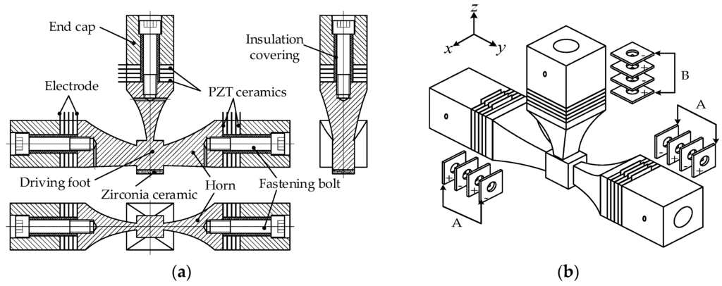
Figure 1.
Structure of the proposed motor: (a) the profile chart of the proposed motor; (b) three-dimensional model. Twelve pieces of piezoelectric (PZT) ceramic plates are classified into two groups and polarized along their thickness directions, as shown in Figure 1b, where “+” and “−” on the PZT ceramic plates represent their polarizations. PZT-A, PZT-B are two groups of PZT ceramic plates which generate longitudinal vibration of horizontal and vertical directions, respectively.
In each horn, four pieces of PZT ceramic plates were stacked together directly. That arrangement of the end caps can get the energy delivered to the horns’ tip ends where the driving foot is located instead of being consumed on the end caps. Mounting holes on the end caps are used for the clamp mechanism to fix the motor on the working platform. Five Beryllium-copper electrodes were arranged among the four PZT ceramics and the motor body. Due to the fact that frictional materials could enhance the friction between the stator and slider, Zirconia ceramics were glued on the bottom of the driving foot with epoxy resin.
3. Operating Principle
Two operating modes, A and B, of the stator are excited to generate the elliptical trajectory on the driving foot, as shown in Figure 2. Two-phase alternating current (AC) voltages are applied on the PZT ceramics of the horizontal transducer and vertical transducer with specific phase differences. Modes A and B, excited by the longitudinal vibration of the vertical and horizontal transducer, produce the vertical and horizontal displacements on the driving foot. The corresponding passive bending vibration is also generated by the coupling effect between transducers. When the resonance frequencies of the two operating modes are near enough, the elliptical trajectory will be generated on the driving foot. The driving ability comes from the frictional force between the interfaces when the slider is in contact with the stator where normal preload is applied. Figure 2a indicates the coupled bending vibration excited in the horizontal transducer, and Figure 2b indicates the coupled bending vibration shape excited in the vertical transducer.
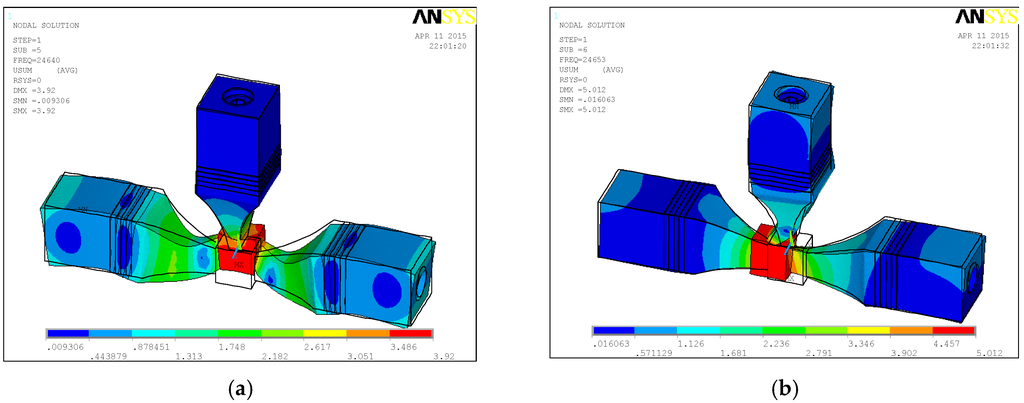
Figure 2.
Two operating modes, A and B, of the stator: (a) Mode A; (b) Mode B.
Figure 3 is the schematic diagram that shows the working principle of the motor. The vibrational shapes of the stator in one vibration cycle are listed in Table 1. According to Table 1, in one vibration cycle, the motor’s working process can be divided into four phases, which are demonstrated as follows.
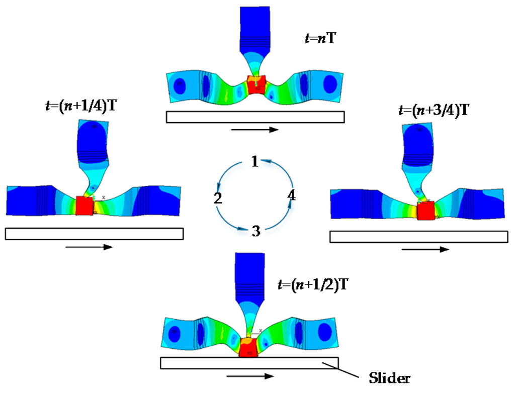
Figure 3.
The working principle of the motor.

Table 1.
The vibrational state of the stator in a period of vibration.
During the first 1/4T phase, the driving foot moves from state 1 to state 2, which is equivalent to the driving foot moving from the top to the left in the anticlockwise direction. Meanwhile, the driving foot levitates over the slider and the motor does not produce the driving force.
- From the 1/4T to 1/2T phase, the driving foot moves from state 2 to state 3 and starts to make contact with the slider. During this period, the motor generates a rightward driving force to actuate the slider.
- In the duration of the third phase, the driving foot moves from the bottom to the right and the motor departs from the slider gradually. The driving force decreases to zero slowly.
- During the last 1/4T phase, the driving foot will be back in its original state. The driving force disappears completely.
4. Design and Analysis
4.1. Structure Optimization and Analysis
In order to improve the output characteristics of the proposed motor, the optimized design for the motor’s configurations can be summarized in the following.
First, compared with the previous motor, the volume of the driving foot has been improved to enhance the contact area with the slider. Furthermore, according to the molecular attraction theory proposed by Bowden and Tabor [21,22], the friction between two metal surfaces could be synthesized as follows:
where Ff, Fa and Fd are the friction force, adhesive friction and ploughing friction. For metal materials, Ff mainly depends on Fa and Fa is determined by Ar and τa, where Ar and τa represent the real contact area and shear strength, respectively. Therefore, enhancing the real contact area between the driving foot and slider can increase the driving friction force. Based on the above theory, the proposed motor’s driving foot has been optimized as a larger rectangular block. However, for ultrasonic motors, it has been considered that an overlarge bottom area of the driving foot will lead to inconformity of the elliptical trajectories of points in the driving area, and this kind of inconformity will make decrease the driving efficiency. As a result, an overlarge bottom area will retard a larger thrust force output. Therefore, a tradeoff between the driving friction force and the driving foot bottom area should be taken into consideration during the design process.
From another point of view, four faces of the horn have been optimized as an exponential shape so that the effect of energy gathering, the vibration amplitude and the vibration velocity on the driving foot can be enhanced.
Finally, considering the fixing positions of the motor, each group of PZT ceramic plates of the previous T-shaped motor were divided into two parts, and the vibration energy of the ceramic plates near the end caps was mostly consumed by the material damping. To overcome this drawback, the modified motor’s fixing points have been set on the end caps, and the energy has been delivered to the horns’ tip ends, where the driving foot is located, instead of being consumed in the end caps. From the analysis above, the proposed motor with a modified structure could enhance the mechanical output performance.
4.2. Modal Analysis and Sensitivity Analysis
The resonance frequencies of Mode A and Mode B should be near enough as an indispensable qualification for the stimulus of the elliptical trajectory at the driving foot, as mentioned above. Hence, it is necessary to explore the relationship between the resonance frequencies of two modes and the structural parameters. By means of FEM software (ANSYS 10.0, ANSYS Inc, Canonsburg, PA, USA), the motor’s finite element model has been built to perform the modal analysis. Afterwards, the resonance frequencies of the two vibration modes were tuned to be close by adjusting the stator’s structural parameters.
Figure 4a shows the section view and the main parameters of the stator, and the initial values of these parameters are listed in Table 2. According to the selected materials and the initial dimensions of the stator, a finite element model was built in ANSYS, as shown in Figure 4b. Duralumin alloy (ρ = 2810 kg/m3, E = 7.2 × 10¹⁰ N/m2, σ = 0.33) was selected to make the T-shaped horn part; meanwhile, steel (ρ = 7850 kg/m3, E = 2.06 × 10¹¹ N/m2, σ = 0.269) is the material of the flange bolt and end caps, and the PZT ceramic material is PZT-4. The mechanical and physical parameters of the PZT ceramics are listed as follows:
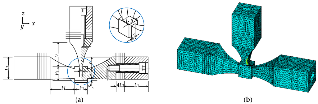
Figure 4.
The section view and finite element model of the stator: (a) The section view and the main parameters of the stator; (b) Finite element model of the stator.
Table 2.
Initial values of the stator’s main parameters (mm).
The exponential-shaped horn is defined by the classical theory of the half-wavelength horn whose length is
where c, f, N are the longitudinal wave velocity, the resonant frequency and the amplitude amplification factor. In general, the longitudinal wave velocity is 5100 m/s in duralumin. Particularly, the horizontal and vertical contraction ratios NH, NV are defined as follows:
where SH1, SV1 represent the horizontal and vertical big end cross-sectional areas of the horns; SH2, SV2 represent their small cross-sectional areas close to the driving foot.
As mentioned before, the horn structure shape and parameters impact the resonant frequency significantly. Besides, from Equation (5) we can obtain that its length is influenced obviously by NH and NV. To reach the purpose of the frequency regulation of two working modes, the contraction ratio parameters, which are convenient for adjusting the horn configurations, are defined as follows:
where a, b, c, d, e, f are shown in Figure 4.
Several parameters were defined as design parameters, as described in Equation (8), to investigate their contributions to the frequency variations of Mode A and Mode B, which are called sensitivities to the modal frequencies. The sensitivities of the design parameters were calculated in ANSYS and shown in Figure 5, where the x axis represents the corresponding variance ratio to their original values and the y axis represents the corresponding resonant frequencies of Mode A and Mode B. According to the sensitivity analysis results, the selected design parameters can be divided into two groups. The design parameters in group one are H1, N1 and N2 which have almost the same sensitivity tendency, and this means that the two working modal frequencies will change in the same direction upon their perturbation, so they play a minor role in frequency degeneration. C1 and C2 are in group two, with different sensitivities to the two working modes, which means Mode A is more sensitive to parameter C1 and Mode B is more sensitive to parameter C2. Thus, the two modals’ frequencies can be separately regulated by adjusting C1 and C2, respectively.
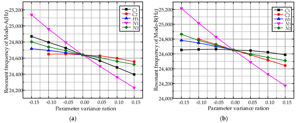
Figure 5.
Sensitivity curves of modal frequencies: (a) Sensitivity curves of Mode A; (b) Sensitivity curves of Mode B.
The degeneration process was performed in three steps. In step one, by adjusting N1 roughly, the two modal frequencies will have great changes and appear in the same frequency range. In step two, altering C1 and C2, respectively, can make the two modal frequencies close enough, which is dominated by the whole degeneration process. In step three, by changing H1 and N2 slightly, the resonant frequency can be degenerated accurately. Finally, the resonant frequencies of Mode A and Mode B were degenerated at 24,640 Hz and 24,653 Hz, respectively. The final structure parameters of the proposed motor are listed in Table 3.
Table 3.
Final values of the stator’s main parameters (mm).
4.3. Transient Analysis of the Ultrasonic Motor
According to the final structural parameters of the stator, the finite element model was built. To test the vibration characteristics of the proposed motor, transient analysis was accomplished by applying two-phase AC 100 Vrms voltages of frequencies 24.645 kHz on the PZT-A and PZT-B ceramic plates with a phase shift 90°. The number of the exciting voltages period is 300 and the transient analysis lasted for about 12.25 ms (the damping coefficient was set as ε = 0.002), as shown in Figure 6a, from which we can tell the transient response comes to a steady state (Δ = 3%) after 10 ms. In order to obtain the motor’s vibration characteristics, the vibration displacements of arbitrarily selected points on the bottom of the driving foot have been extracted, and the center point trajectory in one vibration cycle has been made, as shown in Figure 6. It can be discovered that the point motion trajectory on the surface of the driving foot is elliptical, which is in accordance with the above analysis of the motor working principle.
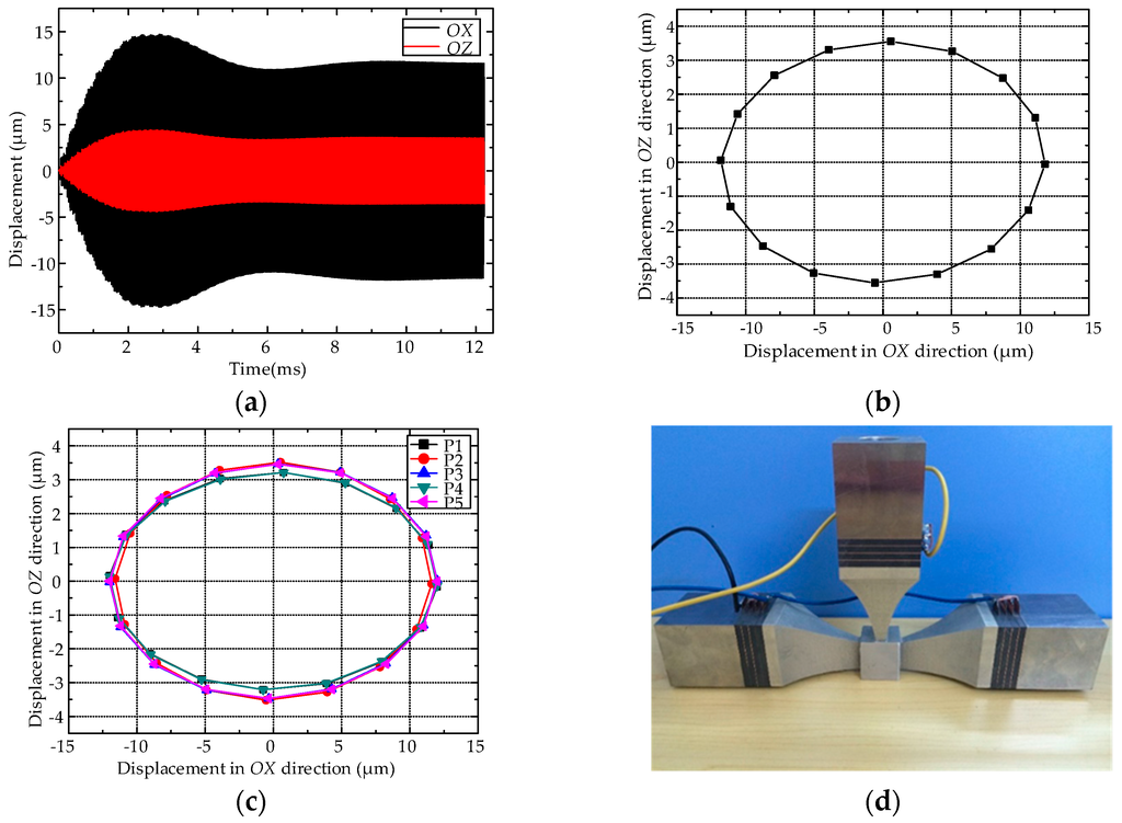
Figure 6.
The elliptical trajectories and prototype of the stator: (a) The displacement response of the center point along OX, OZ direction; (b) The steady motion of the center point in XOZ plane; (c) The elliptical trajectories of driving foot; (d) The prototype of proposed motor.
In order to compare the point elliptical trajectory distribution in different areas of the driving foot, the midpoint and four boundary points on the bottom of the driving foot were selected. By dealing with those five points' trajectory data during the last exciting period, it can be obtained that all five trajectories, as shown in Figure 6c, are elliptical with almost similar amplitudes of longitudinal 12 μm and vertical 3.5 μm, which ensures the friction driving force transmitting at a high efficiency.
5. Experiments
5.1. Vibration Characteristic Experiments
To validate the accuracy of the theoretical analysis and test the characteristics of the proposed motor, a prototype motor has been fabricated according to the above-proposed structure parameters. Figure 6d is the photo of the prototype. The scanning laser Doppler vibrometer (PSV-400-M2, Polytec, Waldbornn, Germany) was adopted to measure the vibration characteristics in the frequency range from 0 kHz to 50 kHz of the motor. Notably, in several close vibration peaks, only choosing the vibration peaks of the frequencies of 24.429 kHz and 24.476 kHz could coincide with the vibration mode of the above theoretical analysis. The modal shapes and vibration spectra of Mode A and Mode B are shown in Figure 7.
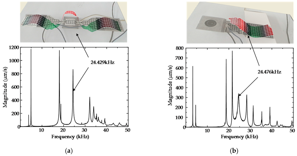
Figure 7.
Mode A and B vibration modes and vibration velocity response spectra: (a) Mode A vibration mode and vibration velocity response spectrum (the side face of the horizontal transducer is the test surface); (b) Mode B vibration mode and vibration velocity response spectrum (the side face of the vertical transducer is the test surface).
The results of the vibration test and the finite element simulation are shown in Table 4. The prototype working modal frequencies of Mode A and Mode B are 24.429 kHz and 24.476 kHz. The relative deviation of the prototype working frequency and the finite element simulation result is less than 1%. The vibration test result agrees well with the FEM analysis calculated result, and this testifies to the rationality of the design method presented in this paper.
Table 4.
Comparison between the finite element simulation and the prototype working frequency.
5.2. Mechanical Output Performance Experiments
An experimental platform has been designed and fabricated to verify the correctness of the theory and analysis. Figure 8 shows the three-dimensional model and section view of the experimental platform. It consists of the stator installation platform, the slider guide rail, the load installation sliding table, and the data acquisition. By altering the inertia load and preload, the slider’s displacement and velocity curves could be measured from the data acquisition, and the maximum initial acceleration could be easy to calculate via the velocity curves. Eventually, the output thrust could be figured out by multiplying the acceleration by the inertia load.
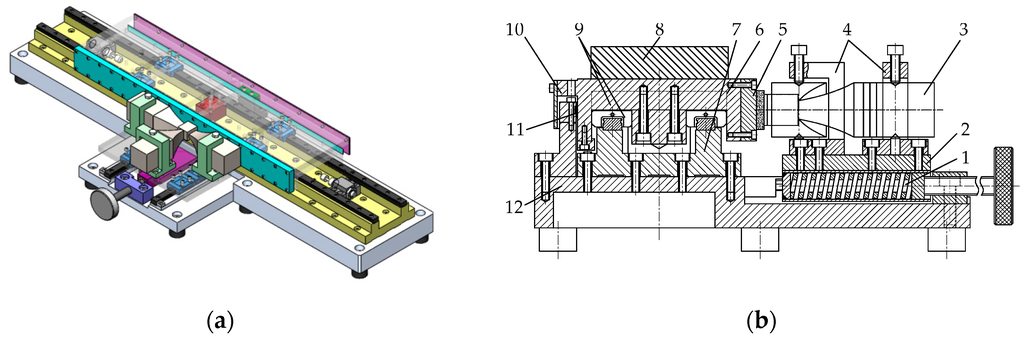
Figure 8.
Experimental platform structure diagram: (a) The 3D model of general linear ultrasonic motor experimental platform; (b) The side-view of general experimental platform. 1. thrust spring; 2. stator mounting plate; 3. Motor; 4. motor mounting bracket; 5. friction material installation plate; 6. load sliding table; 7. guide rail installation pedestal; 8. inertia load block; 9. guide rail sliding block; 10. reading head; 11. grating scale; 12. experimental platform pedestal.
The motor’s mechanical output characteristics could be tested on the manufactured experimental platform illustrated in Figure 9a. As shown in Figure 9b, the non-loaded optimal operating frequency is 24.55 kHz. While improving the output thrust, the speed is also guaranteed to reach the best state, so the exciting frequency is set as 24.55 kHz in the latter experiment. When the exciting voltage is 150 Vrms, on the condition of no force load and a 15 kg inertia load, the motor output thrust and velocity curves are presented in Figure 10a and in Figure 10b, respectively.
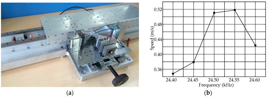
Figure 9.
The real image of experimental platform and the speed curve: (a) The real image of experimental platform; (b) The speed curve of optimal operating frequency.
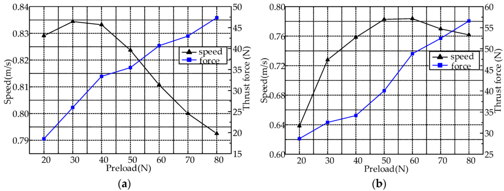
Figure 10.
The mechanical output performance of the prototype: (a) Plot of the no-load speed and force under the voltage of 150 Vrms; (b) Plot of a 15 kg inertia load speed and force under the voltage of 150 Vrms.
According to the above measured results, when the exciting voltage is 150 Vrms, the proposed LUSM non-loaded maximum velocity is 0.83 m/s and the maximum output thrust can even reach 56 N. A comparison between the proposed T-shape piezoelectric motor and a previous one with a similar principle [15] is listed in Table 5. The maximum power of the modified motor is nearly six times that of the previous motor when the preload is 80 N with a 15 kg inertia load. Hence, the proposed LUSM output thrust characteristic has a huge enhancement.
Table 5.
Comparison between the proposed motor and the previous one.
6. Conclusions
In this paper, we proposed a modified LUSM that is capable of outputting a high driving force. The mechanical output characteristic has been tested, and it can be obtained that the characteristic frequency is 24.45 kHz. The typical output of the prototype is a non-loaded maximum velocity of 0.83 m/s and a maximum thrust force of 56 N at a voltage of 150 Vrms. According to the test results, it reveals that the horn and the driving foot have significant effects on the mechanical output characteristic. The driving foot area has made an indelible contribution to the increment of the output thrust. By modifying the above two parts, the two working modes can be degenerated and the mechanical output characteristic shows an observable enhancement.
Acknowledgments
This project was supported by the National Natural Science Foundation of China (51575124, 51375107).
Author Contributions
All authors conceived and designed the experiments and analyzed the data; Sijia Shao and Shengjun Shi accomplished the FEM analysis; all authors contributed to the writing of the paper.
Conflicts of Interest
The authors declare no conflict of interest.
References
- Ueha, S.; Tomikawa, Y.; Kurosawa, M.; Nakamura, N. Ultrasonic Motors: Theory and Applications; Oxford University Press: Oxford, UK, 1993; pp. 1–20. [Google Scholar]
- Zhao, C.S. Recent progress in ultrasonic motor techniques. J. Vib. Meas. Diagn. 2004, 24, 1–5. [Google Scholar]
- Zhao, C.S. Ultrasonic Motors: Technologies and Applications; Science Press: Beijing, China, 2007; pp. 1–11. [Google Scholar]
- Spanner, K.; Vyshneevskyy, O.; Wishnewskiy, W. New Linear Ultrasonic Micromotor for Precision Mechatronic Systems. In Proceedings of the Actuator 2006: 10th International Conference on New Actuator, Bremen, Germany, 14–16 June 2006.
- Lu, X.; Hu, J.; Zhang, Q.; Yang, L.; Zhao, C.; Vasiljev, P. An ultrasonic driving principle using friction reduction. Sens. Actuators A: Phys. 2013, 199, 187–193. [Google Scholar] [CrossRef]
- Li, X.; Ci, P.; Liu, G.; Dong, S. A two-layer linear piezoelectric micromotor. IEEE Trans. Ultrason. Ferroelectr. Freq. Control 2015, 62, 405–411. [Google Scholar] [CrossRef] [PubMed]
- Guo, M.; Pan, S.; Hu, J.; Zhao, C.; Dong, S. A small linear ultrasonic motor utilizing longitudinal and bending modes of a piezoelectric tube. IEEE Trans. Ultrason. Ferroelectr. Freq. Control 2014, 61, 705–709. [Google Scholar] [CrossRef]
- Shafik, M.; Abdalla, H.S.; Fransson, P. A piezoelectric servo feed drive for electro discharge machining system industrial applications using linear ultrasonic motor. J. Manuf. Sci. Eng. 2013. [Google Scholar] [CrossRef]
- Ci, P.; Liu, G.; Chen, Z.; Dong, S. A standing wave linear ultrasonic motor operating in face-diagonal-bending mode. Appl. Phys. Lett. 2013. [Google Scholar] [CrossRef]
- Chen, Z.; Li, X.; Ci, P.; Liu, G.; Dong, S. A standing wave linear ultrasonic motor operating in in-plane expanding and bending modes. Rev. Sci. Instrum. 2015. [Google Scholar] [CrossRef] [PubMed]
- Yuan, S.; Zhu, C.; Chu, X.; Zhao, Y.; Amin, M.; Fan, Y. A novel linear piezoelectric actuator with two working principles of standing and traveling wave vibration mode. AIP Adv. 2015. [Google Scholar] [CrossRef]
- Liu, Y.; Chen, W.; Xu, D.; Feng, P.; Liu, J. Improvement of a rectangle-shape linear piezoelectric motor with four driving feet. Ceram. Int. 2015, 41, 594–601. [Google Scholar] [CrossRef]
- Kurosawa, M.K.; Kodaira, O.; Tsuchitoi, Y.; Higuchi, T. Transducer for high speed and large thrust ultrasonic linear motor using two sandwich-type vibrators. IEEE Trans. Ultrason. Ferroelectr. Freq. Control 1998, 45, 1188–1195. [Google Scholar] [CrossRef] [PubMed]
- Yun, C.H.; Ishii, T.; Nakamura, K.; Ueha, S.; Akashi, K. A high power ultrasonic linear motor using a longitudinal and bending hybrid bolt-clamped Langevin type transducer. Jpn. J. Appl. Phys. 2001, 40, 3773–3776. [Google Scholar] [CrossRef]
- Liu, Y.; Chen, W.; Liu, J.; Shi, S. A high-power linear ultrasonic motor using longitudinal vibration transducers with single foot. IEEE Trans. Ultrason. Ferroelectr. Freq. Control 2010, 57, 1860–1867. [Google Scholar] [PubMed]
- Liu, Y.; Liu, J.; Chen, W.; Shi, S. A U-shaped linear ultrasonic motor using longitudinal vibration transducers with double feet. IEEE Trans. Ultrason. Ferroelectr. Freq. Control 2012, 59, 981–989. [Google Scholar] [CrossRef] [PubMed]
- Liu, Y.; Chen, W.; Liu, J.; Yang, X. A high-power linear ultrasonic motor using bending vibration transducer. IEEE Trans. Ind. Electron. 2013, 60, 5160–5166. [Google Scholar] [CrossRef]
- Liu, Y.; Chen, W.; Liu, J.; Shi, S. A rectangle-type linear ultrasonic motor using longitudinal vibration transducers with four driving feet. IEEE Trans. Ultrason. Ferroelectr. Freq. Control 2013, 60, 777–785. [Google Scholar] [CrossRef] [PubMed]
- Hua, S.; Meng, Y.; Lou, Y.; Li, Z.; Wang, X. Screw-type actuator driven by piezoelectric transducers. Adv. Mech. Eng. 2015. [Google Scholar] [CrossRef]
- Chu, X.; Wang, J.; Yuan, S.; Li, L.; Cui, H. A screw-thread-type ultrasonic actuator based on a Langevin piezoelectric vibrator. Rev. Sci. Instrum. 2014. [Google Scholar] [CrossRef] [PubMed]
- Bowden, F.P.; Leben, L. The Friction and Lubrication of Solids, Part I; Clarendon Press: Oxford, UK, 1950. [Google Scholar]
- Bowden, F.P.; Leben, L. The Friction and Lubrication of Solids, Part II; Clarendon Press: Oxford, UK, 1964. [Google Scholar]
© 2016 by the authors; licensee MDPI, Basel, Switzerland. This article is an open access article distributed under the terms and conditions of the Creative Commons by Attribution (CC-BY) license (http://creativecommons.org/licenses/by/4.0/).