
Analysis of Sheet Metal Tapping Screw Fabrication Using a Finite Element Method

Abstract
:1. Introduction
1.1. Research Motivation
- (a)
- Recruiting specialists in thread plate design is difficult and this traditional industry can hardly survive in the current environment. Also, current salaries are not generally attractive to qualified professionals.
- (b)
- The shortage of CAD and CAE designers is a significant problem for businesses that seek to increase the value provided by screws without giving away trade secrets. This dilemma is real, as newly developed products may involve a complicated thread for which a thread flat-die manufacturer must develop a mold, the existence of which may result in the sharing of confidential data.
- (c)
- A complicated thread form cannot be easily simulated using CAD and forming analysis software. Training designers using the feedback design curve, based on the experience of a mold manufacturer, takes a long time and is costly, and is unacceptable to the industry.
1.2. Literature Review
2. Fundamental Theory
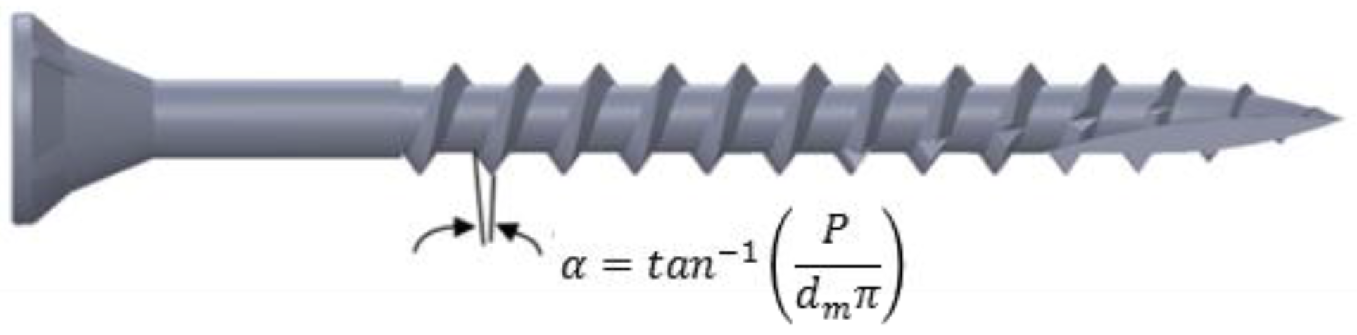
2.1. Screw Thread Theory
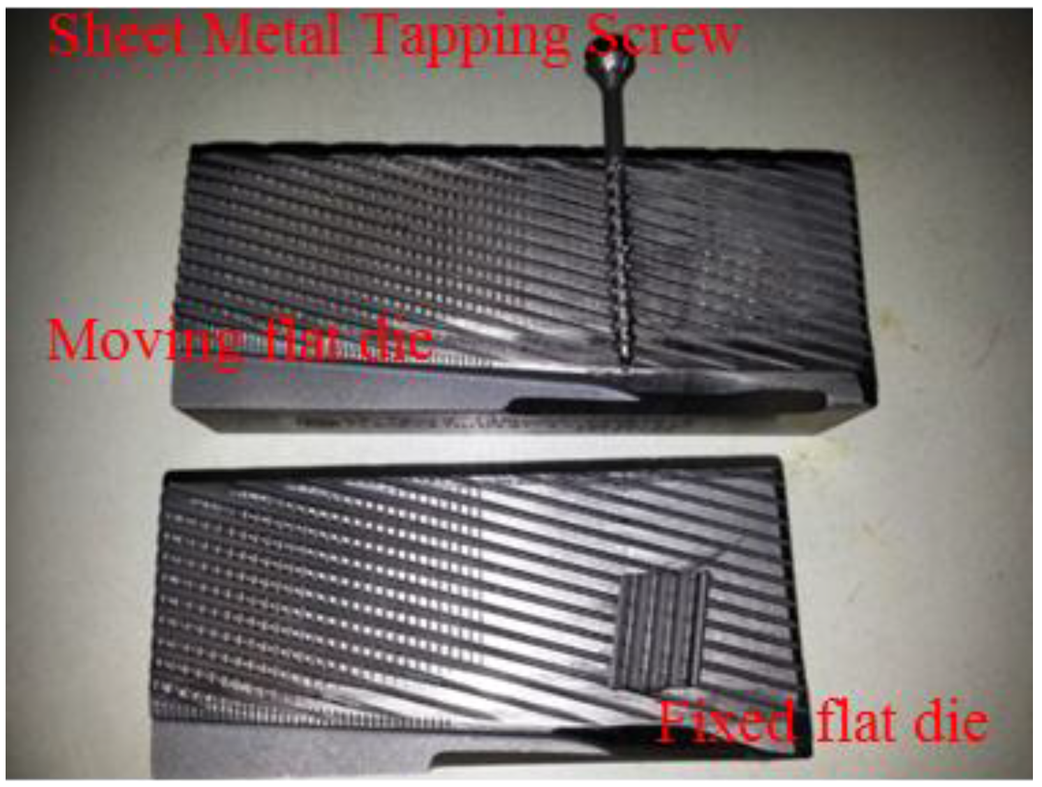
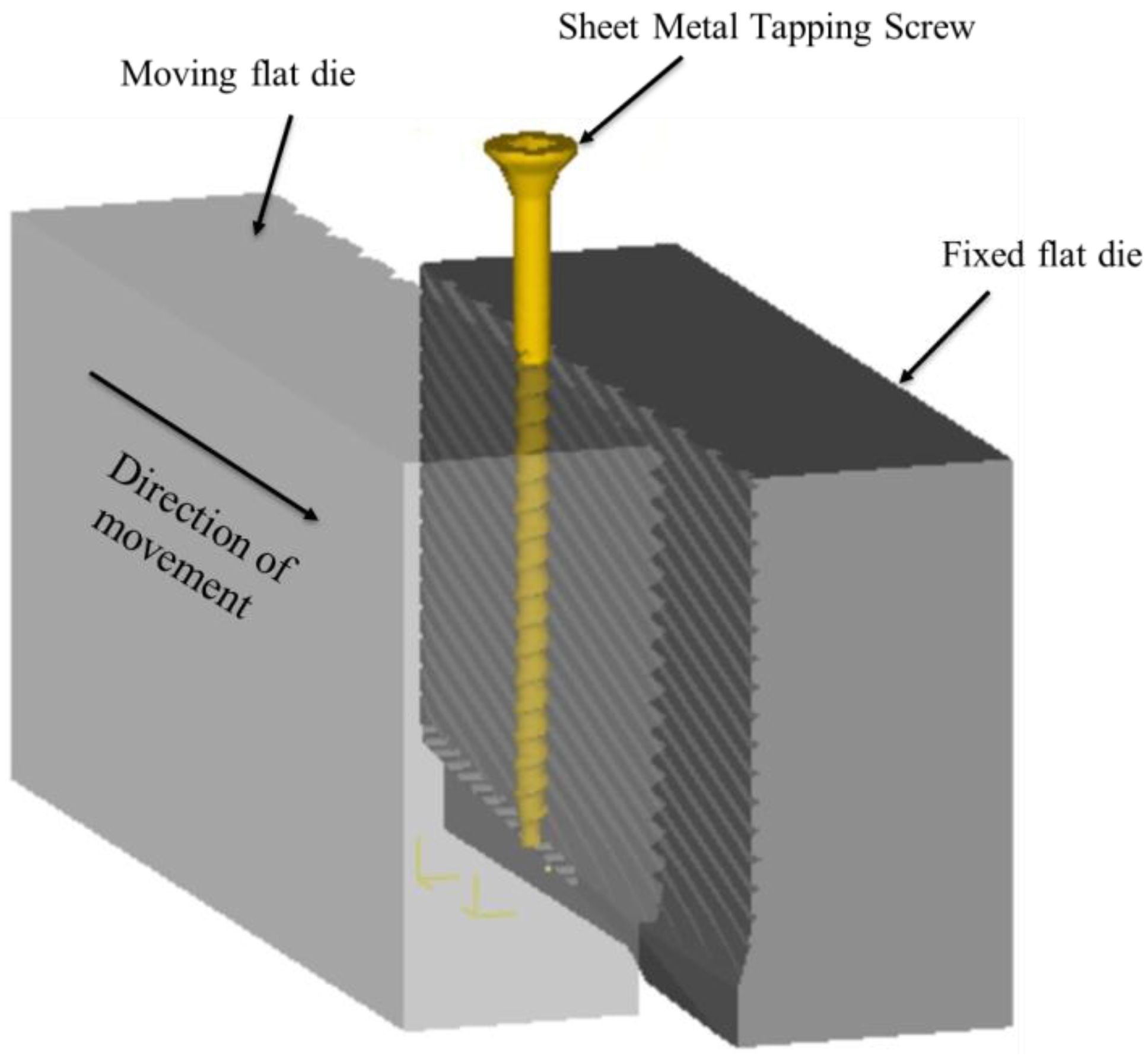
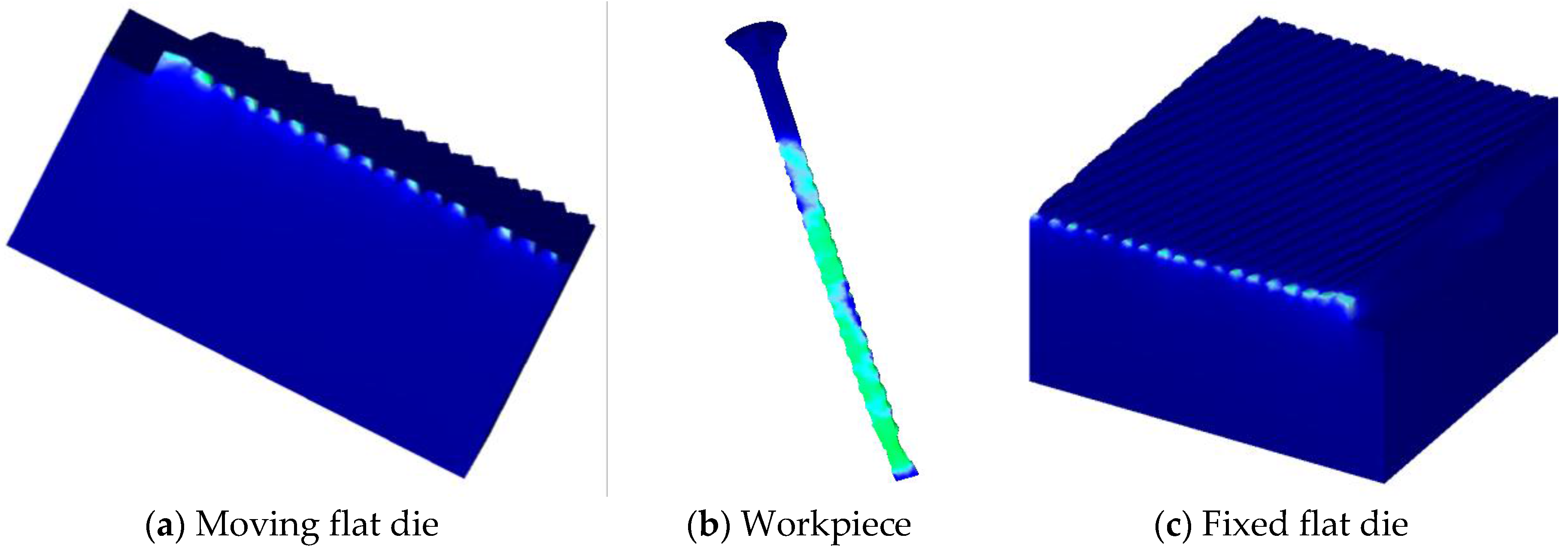
2.2. Brief Introduction to Flat-Die Thread Rolling
2.3. Geometric Construction of Screw and Thread Plate
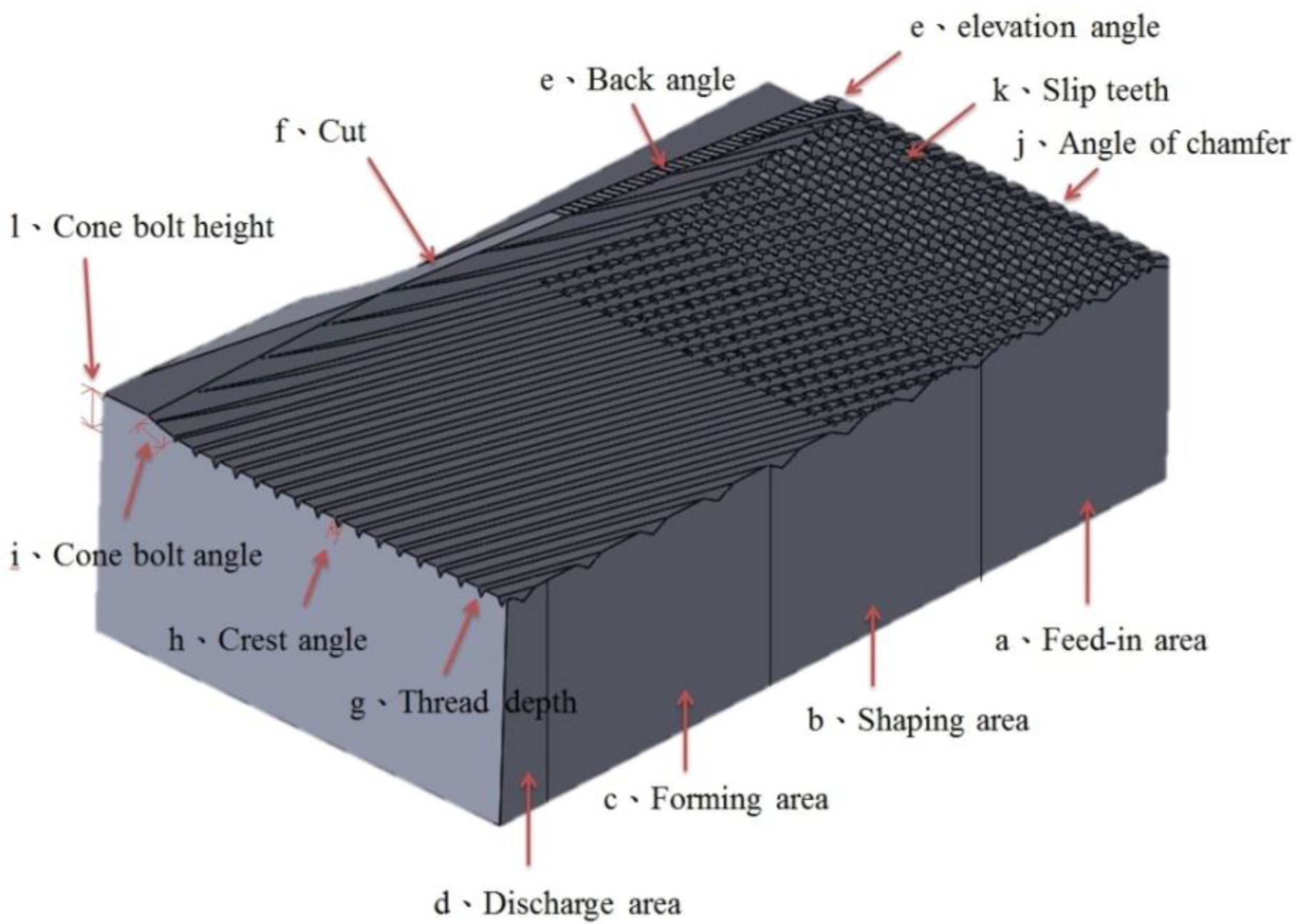
- (a)
- Feed-in area: the portion where a light nail is fed in and compressed in the turning process. The feed-in area and shaping area are often within carved slip teeth.
- (b)
- Shaping area: the area where the light nail, after passing the feed-in area, is extruded and formed.
- (c)
- Forming area: the area where the light nail, after passing the feed-in area and the shaping area, is extruded into screws, in a manner that is determined by the thread grooves of the thread plate, the thread peak, and the cone bolt angle.
- (d)
- Discharge area: the portion where formed screws are discharged.
- (e)
- Back angle and elevation angle: the portion where the cone bolt thread plate is cut to form the tip. The back angle controls the feed-in of the material in that a large back angle allows more material to be fed in and a small back angle reduces material feed. The elevation angle is the essential parameter in the forming of the thread tip and thread peak on the thread tip. Small elevation angles result in trailing as the tail is not cut cleanly. Larger elevation angles cause broken tips because the light nail is cut too early.
- (f)
- Cut: crossing of the back angle and screw thread plate cone bolts. A sharp cut is required as a blunt cut results in trailing and inconsistent tip forming.
- (g)
- Thread depth: depth of the screw thread peak, which controls the outer diameter of the screw.
- (h)
- Crest angle: the angle of the screw thread peak. Specific screw crest angles are required to meet particular specifications; for example, a C/B chipboard nail has a crest of 40 degrees; a general BA round-tail screw has a crest of 47.5 degrees; a general triangular self-tapping thread has a crest of 45 degrees, and a general machine thread has a crest of 58~60 degrees. Crest angle is also critical in controlling the outer diameter of the screw.
- (i)
- Cone bolt angle: screw tip angle. General self-tapping screw tips have angles of 40~50 degrees. Specific screws must meet particular specifications; for example, general wallboard nail and chipboard nail tips have angles of 20~30 degrees. Customers sometimes specify tip angles.
- (j)
- Angle of chamfer: the feed-in area and shaping area that are milled sharply in the thread plate production process for easy feed-in. When the angle of chamfer is too small, the thread plate is not abrasion-resistant. When the angle of chamfer is too large, the tail feed-in area is too large, making screw forming difficult, and the outer diameter too small. When chamfer in the feed-in area is greatly worn, the screws are not sufficiently formed and the screw diameter will be too large to support slipping.
- (k)
- Slip teeth: threads that are specially carved on the thread plate feed-in area and the forming area to prevent a light nail from slipping in the feed-in process. Shallow slip teeth cause slipping, while deep slip teeth result in roughened screw bottoms, dim thread peaks, and even blocking of the extrusion of light nails, causing the outer diameters of the screws to be too small.
- (l)
- Cone bolt height: the distance between the thread plate surface and the cut, which is generally half of the bottom diameter of the screw. Cone bolts that are too high cause the screw cut to bump together, causing insufficient screw forming. A cone bolt that is too low causes trailing because the tail is not cut off.
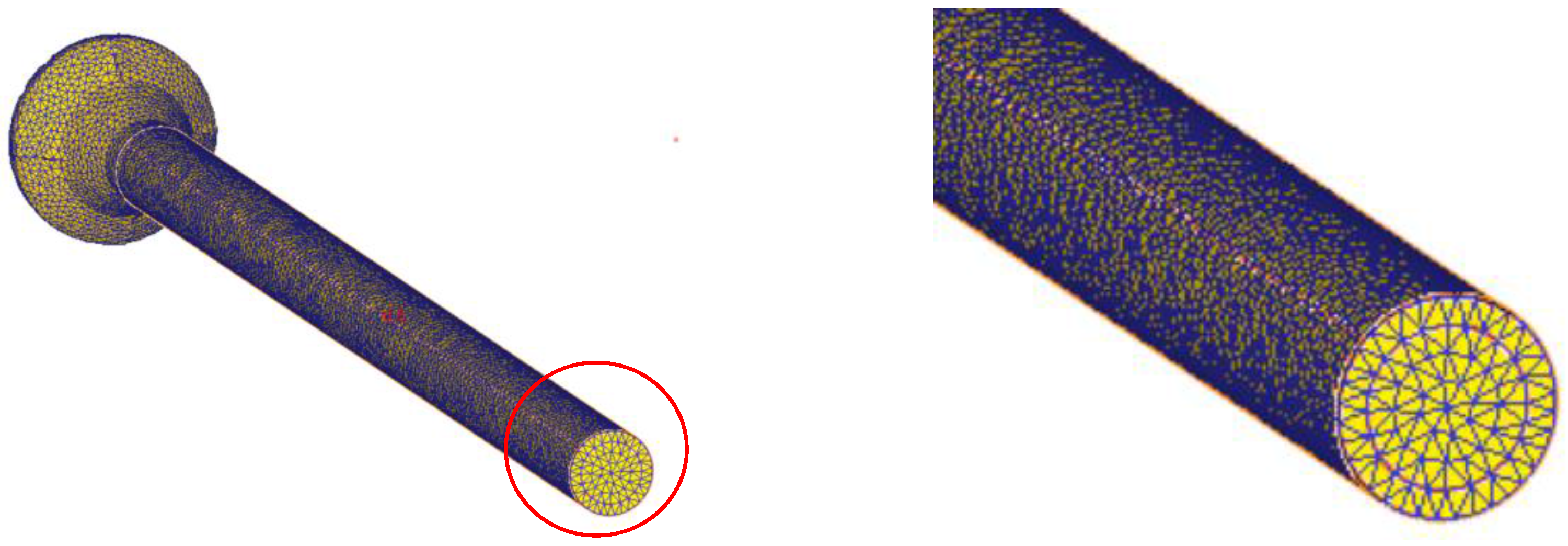
2.4. Mathematical Theory of DEFORM-3D
2.5. Cold Forging Theory
- (a)
- Elastic deformations are neglected.
- (b)
- The deforming material is considered to be in continuum (metallurgical aspects such as grains, grain boundaries, and dislocations are not considered).
- (c)
- Anisotropy and Bauschinger effects are neglected. Volume remains constant. In this study, we assume the workpiece is homogeneous and isotropic, ignoring the effects of direction on stress yield that von Mises asserted should be considered.
- (d)
- Yield criterion
- (e)
- Friction is expressed by a simplified expression such as Coulomb’s law or by a constant shear stress.
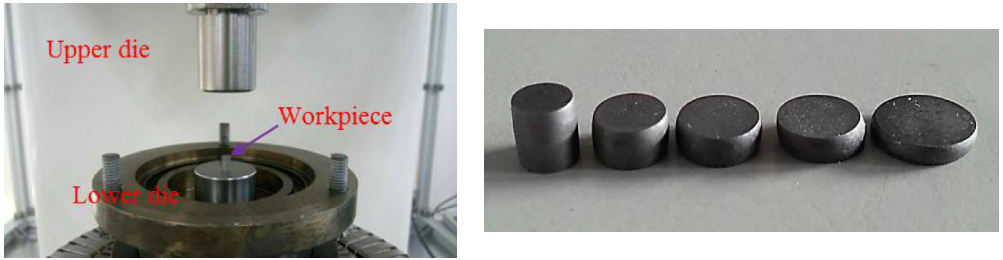
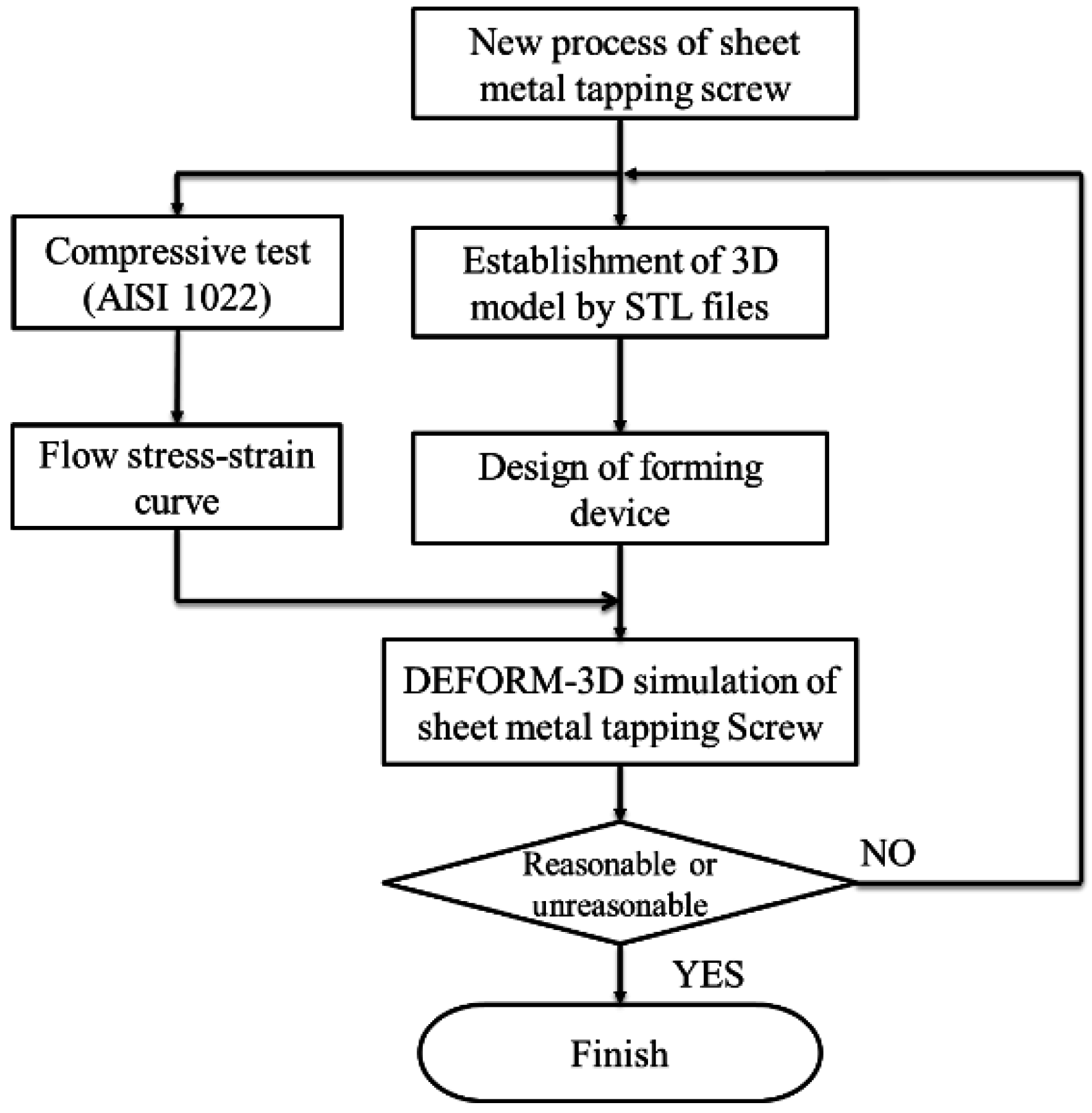
3. Research Methodology
- (a)
- To predict the required forming load to support the design or selection of proper dies and thread rolling machines.
- (b)
- To model material flow (stress, strain, and velocity field) to evaluate thread plate design and material selection.
- (c)
- To determine simulation parameters to further thread plate design.
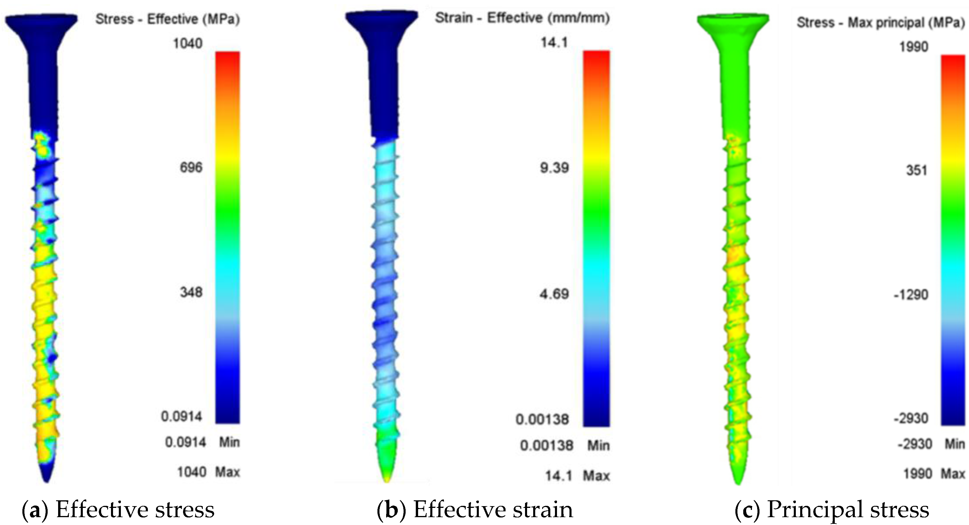
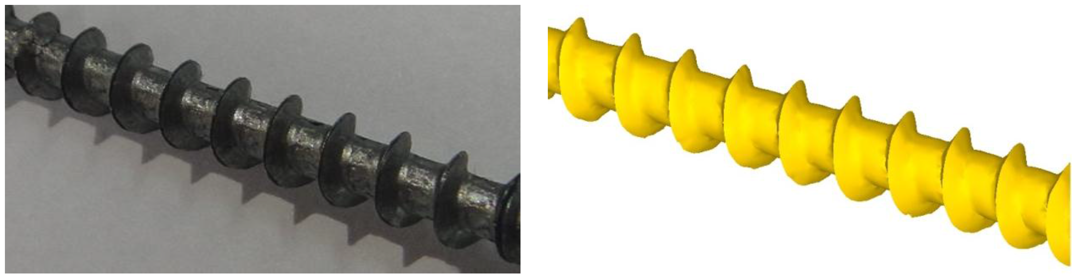
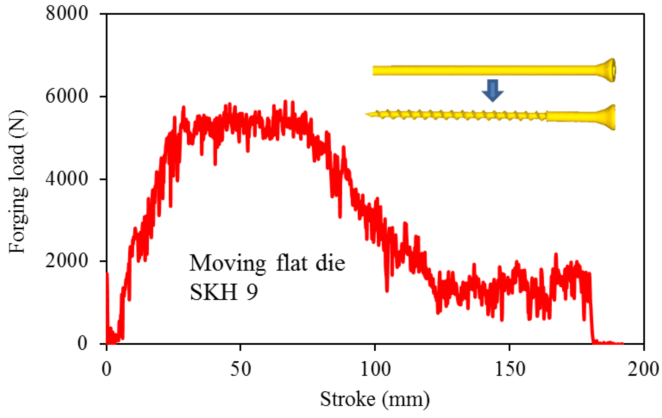
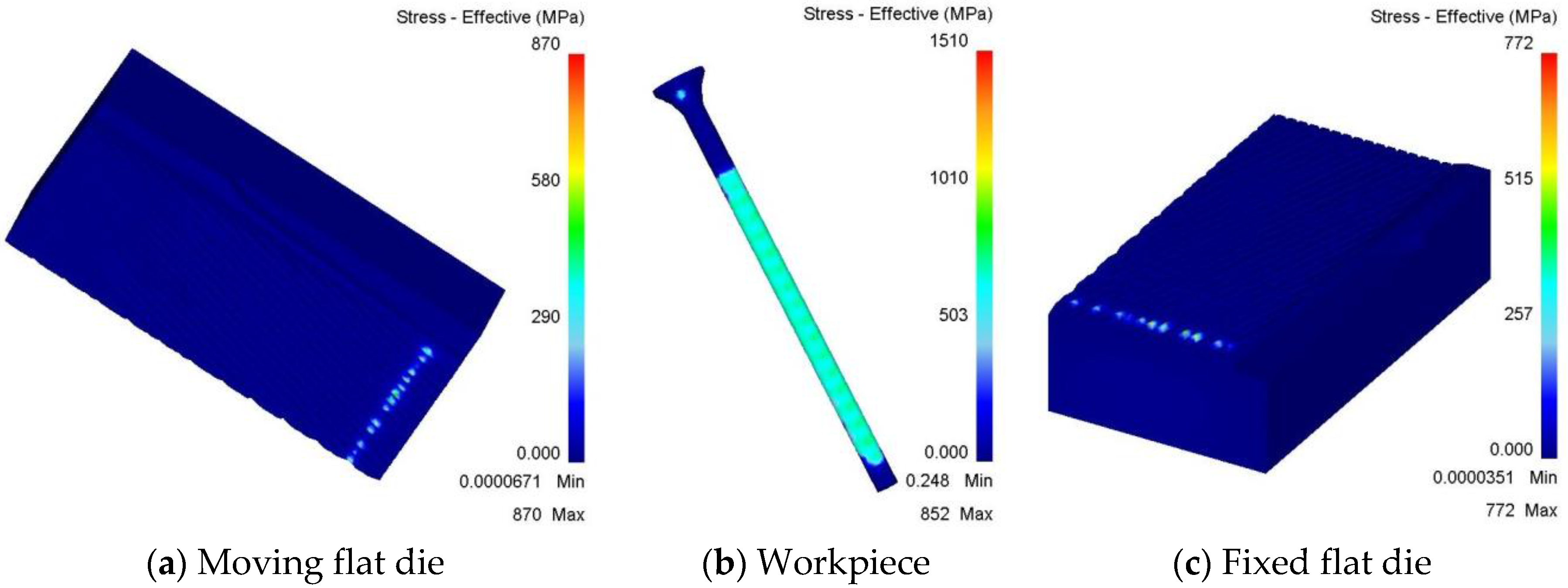
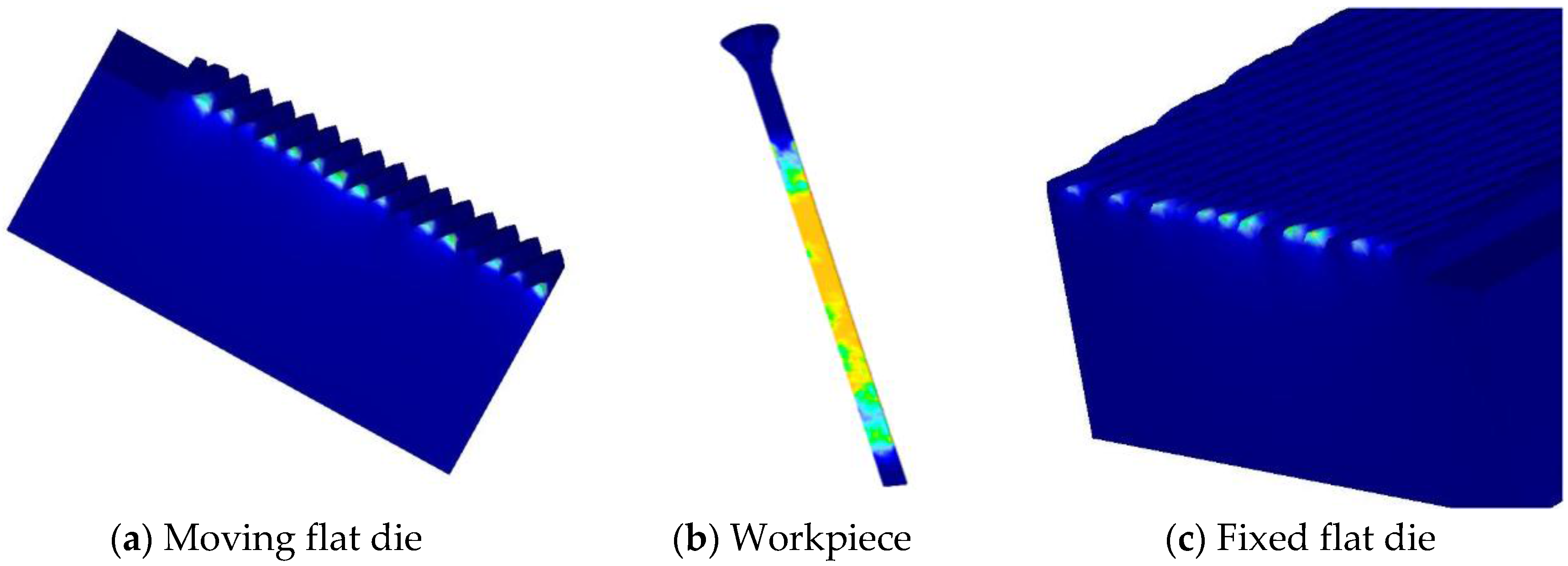
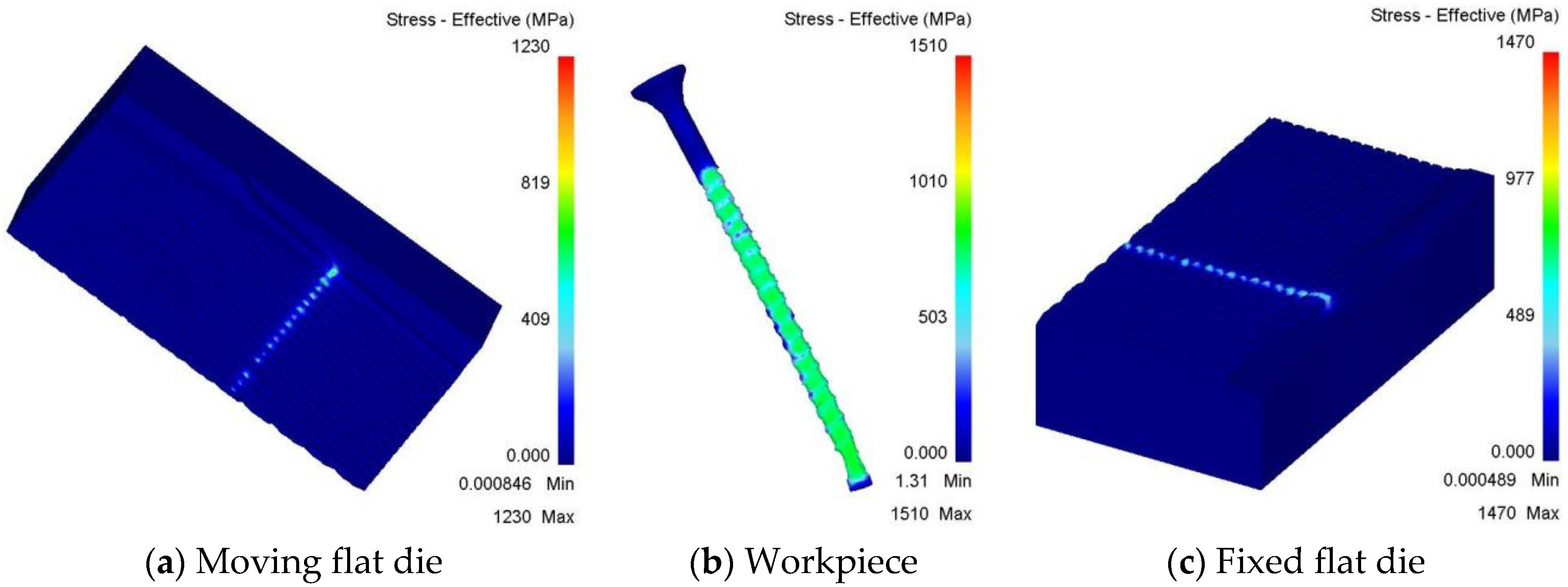
4. Results and Discussion
5. Conclusions
- (1)
- A combination of CAD and CAE can replace the trial-and-error method or worker experience for determining the plastic deformation of screw threading processes.
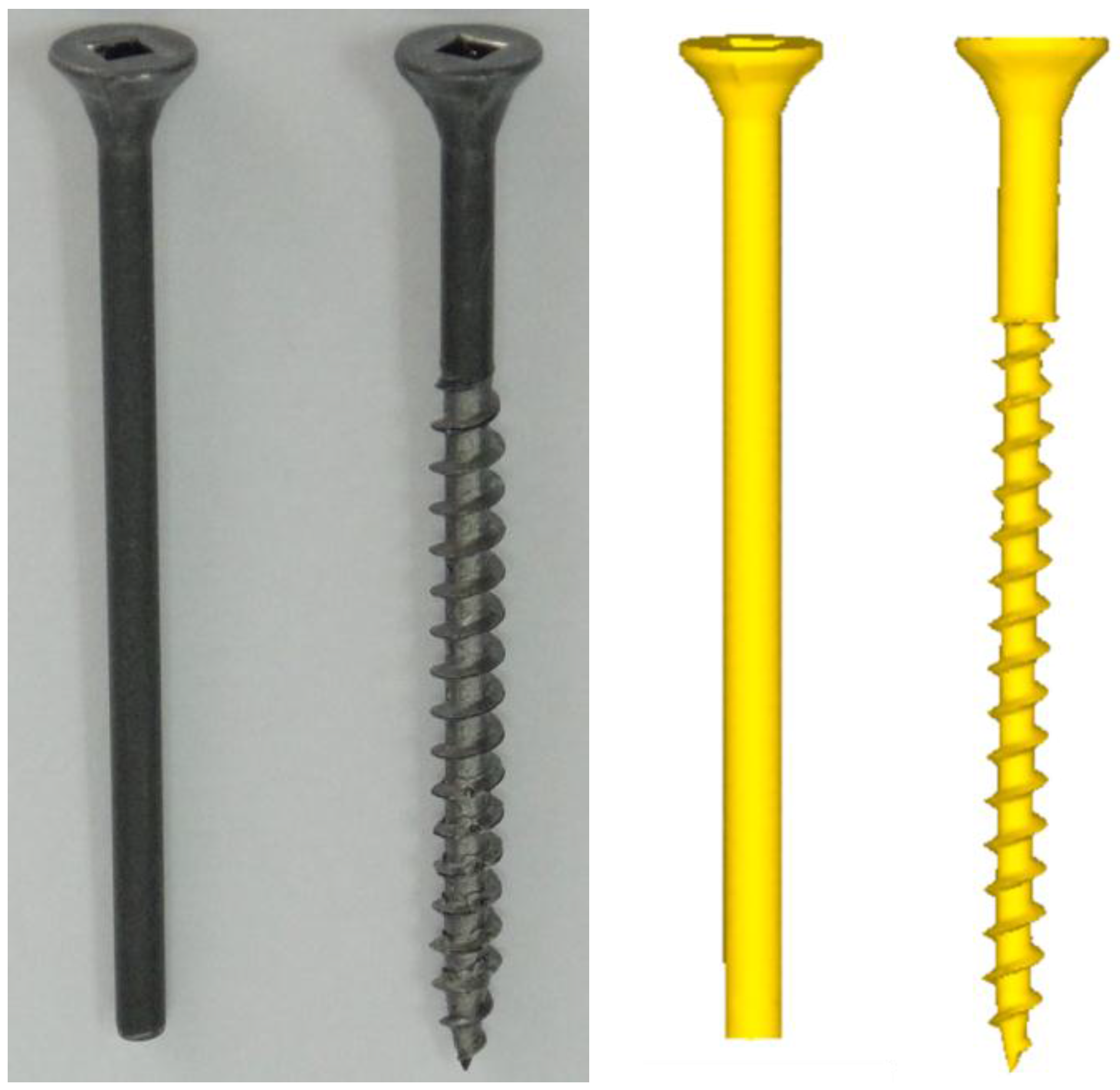
- (2)
- Comparing simulated and actual sizes of the produced sheet metal tapping screw reveals that the sheet metal tapping screw forging size errors were less than 0.9%, except for the 3.075% error with a small angle, demonstrating the accuracy of the simulated forming process.
- (3)
- The forming process can be used to reduce the number of die tests and to improve the quality and properties of formed tapping screws.
Acknowledgments
Author Contributions
Conflicts of Interest
References
- O’Connell, M.; Painter, B.; Maul, G.; Taylan, A. Flashless closed-die upset forging-load estimation for optimal cold header selection. J. Mater. Process. Technol. 1996, 59, 81–94. [Google Scholar] [CrossRef]
- Kim, H.; Altan, T. Cold forging of steel-practical examples of computerized part and process design. J. Mater. Process. Technol. 1996, 59, 122–131. [Google Scholar] [CrossRef]
- Liou, J.H.; Jang, D.Y. Forging parameter optimization considering stress distributions in product through FEM analysis and robust design methodology. Int. J. Mach. Tools Manuf. 1997, 37, 775–782. [Google Scholar] [CrossRef]
- Joun, M.S.; Lee, S.W.; Chung, J.H. Finite element analysis of a multi-stage axisymmetric forging process. Int. J. Mach. Tools Manuf. 1998, 38, 843–854. [Google Scholar] [CrossRef]
- Vazquez, V.; Hannan, D.; Altan, T. Tool life in cold forging–example of design improvement to increase service life. J. Mater. Process. Technol. 2000, 98, 90–96. [Google Scholar] [CrossRef]
- Falk, B.; Engel, U.; Geiger, M. Fundamental aspects for the evaluation of the fatigue behavior of cold forging tools. J. Mater. Process. Technol. 2001, 119, 158–164. [Google Scholar] [CrossRef]
- Janicek, L.; Petruska, J.; Maros, B.; Rusz, S. Clod forming of bolts without thermal treatment. J. Mater. Process. Technol. 2002, 125–126, 341–346. [Google Scholar] [CrossRef]
- Min, D.; Kim, M. A study on precision cold forging process improvements for the steering yoke of automobiles by the rigid–plastic finite-element method. J. Mater. Process. Technol. 2003, 138, 339–342. [Google Scholar] [CrossRef]
- Liu, G.L.; Zhang, B.X.; Hu, L.; Wang, Z.R.; Huang, S.D.; Tang, Q.B. Applications of numerical simulation to the analysis of bulk-forming processes—Case studies. J. Mater. Process. Technol. 2004, 150, 56–61. [Google Scholar] [CrossRef]
- Sofuoglu, H.; Gedikli, H. Physical and numerical analysis of three dimensional extrusion process. Comput. Mater. Sci. 2004, 31, 113–124. [Google Scholar] [CrossRef]
- Kim, M.S.; Choi, J.C.; Kim, Y.H.; Kim, C.; Park, C.W. The development of an automated process planning and die design system for multi former-bolt products. Int. J. Mach. Tools Manuf. Technol. 2004, 24, 288–297. [Google Scholar] [CrossRef]
- Kim, H.S. A study on cold forging process sequence design of terminal pins for high-voltage capacitors. J. Mater. Process. Technol. 2007, 187–188, 604–608. [Google Scholar] [CrossRef]
- Jun, B.Y.; Kang, S.M.; Lee, M.C.; Park, R.H.; Joun, M.S. Prediction of geometric dimensions for cold forgings using the finite element method. J. Mater. Process. Technol. 2007, 189, 459–465. [Google Scholar] [CrossRef]
- Lv, C.; Zhang, L.; Mu, Z.; Taib, Q.; Zheng, Q. 3D FEM simulation of the multi-stage forging process of a gas turbine compressor blade. J. Mater. Process. Technol. 2008, 198, 463–470. [Google Scholar] [CrossRef]
- Hsia, S.Y. Improved manufacturing process for movable retaining pins using optimization method. Trans. Can. Soc. Mech. Eng. 2015, 39, 379–396. [Google Scholar]
- Hsia, S.Y.; Shih, P.Y. Wear improvement of tools in the cold forging process for long hex flange nuts. Materials 2015, 8, 6640–6657. [Google Scholar] [CrossRef]
- Landeta, J.F.; Valdivielso, A.F.; de Lacalle, L.L.; Girot, F.; Pérez, J.P. Wear of Form Taps in Threading of Steel Cold Forged Parts. J. Manuf. Sci. Eng. 2015, 137. [Google Scholar] [CrossRef]
- Urbikain, G.; Perez, J.M.; de Lacalle, L.N.L.; Andueza, A. Combination of friction drilling and form tapping processes on dissimilar materials for making nutless joints. Proc. Inst. Mech. Eng. B J. Eng. Manuf. 2016. [Google Scholar] [CrossRef]


| Type of Mesh Element | Tetrahedron |
|---|---|
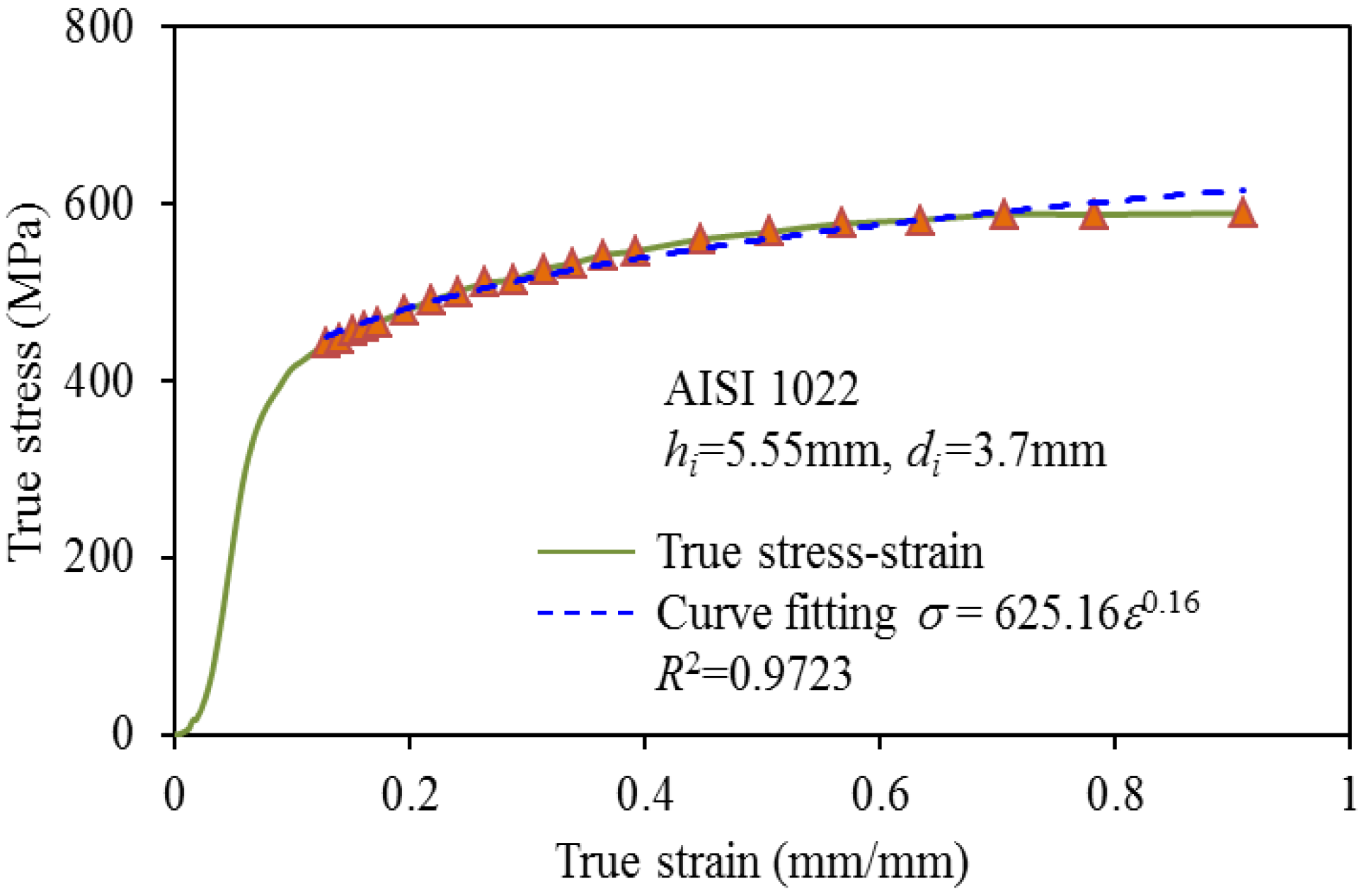
| Workpiece material | AISI 1022 |
| Flat dies | SKH 9 |
| True stress-strain curve | σ = 625.16ε0.16 |
| Blank/die property | Plastic body/rigid (elastic) body |
| Temperature | 20 °C |
| Die speed | 10 mm/s |
| Mesh number (workpiece/flat die) | 80,000/300,000 |
 | |||
|---|---|---|---|
| Dimension | Exp. ± SD | FEM ± SD | Error (%) |
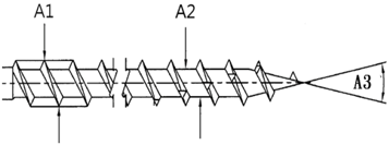
| A1 (mm) | 4.32 ± 0.0049 | 4.32 ± 0.0043 | 0.085 |
| A2 (mm) | 2.64 ± 0.0171 | 2.62 ± 0.0029 | 0.884 |
| A3 (°) | 23.73 ± 1.0333 | 24.46 ± 0.9587 | 3.075 |
© 2016 by the authors; licensee MDPI, Basel, Switzerland. This article is an open access article distributed under the terms and conditions of the Creative Commons Attribution (CC-BY) license (http://creativecommons.org/licenses/by/4.0/).
Share and Cite
Hsia, S.-Y.; Chou, Y.-T.; Lu, G.-F. Analysis of Sheet Metal Tapping Screw Fabrication Using a Finite Element Method. Appl. Sci. 2016, 6, 300. https://doi.org/10.3390/app6100300
Hsia S-Y, Chou Y-T, Lu G-F. Analysis of Sheet Metal Tapping Screw Fabrication Using a Finite Element Method. Applied Sciences. 2016; 6(10):300. https://doi.org/10.3390/app6100300
Chicago/Turabian StyleHsia, Shao-Yi, Yu-Tuan Chou, and Guan-Fan Lu. 2016. "Analysis of Sheet Metal Tapping Screw Fabrication Using a Finite Element Method" Applied Sciences 6, no. 10: 300. https://doi.org/10.3390/app6100300
APA StyleHsia, S.-Y., Chou, Y.-T., & Lu, G.-F. (2016). Analysis of Sheet Metal Tapping Screw Fabrication Using a Finite Element Method. Applied Sciences, 6(10), 300. https://doi.org/10.3390/app6100300