Abstract
In this paper, we propose a signal intelligence (SIGINT) drone swarm system with a three-dimensional (3-D) volumetric self-complementary array configuration. In the proposed system, multiple drones form two array layers separated along the boresight direction of the system, providing sufficient spacing between drones mounting an antenna element. The antenna elements in one array layer are arranged in a complementary manner to fill empty spaces in the other layer, allowing the system to maximize the number of drones deployed within the aperture area. As a result, the effective electrical spacing at 300 MHz is reduced from 1.7λ and 0.9λ to 0.85λ and 0.45λ along the x- and y-axes, respectively. The array gains of the proposed system are 3.96 dBi, 6.40 dBi, and 15.3 dBi at 100 MHz, 200 MHz, and 300 MHz, and the side-lobe levels (SLLs) are −13.0 dB, −12.7 dB, and −13.0 dB. In addition, the proposed drone swarm SIGINT system is evaluated in a practical SIGINT environment that considers terrain features, and then the detection performance is compared with those of conventional ground-based and airborne SIGINT systems. In this SIGINT scenario, the proposed system can detect signals over an extended detection range of 150 km than those of ground-based and airborne systems.
1. Introduction
In modern radio frequency (RF) environments, demands for monitoring and identifying signal sources over wide areas and across multiple frequency bands are increasing [1,2,3]. In accordance with these demands, signal intelligence (SIGINT) systems are often used to collect and analyze RF signals generated by various RF systems [4,5]. For accurately detecting signals at long distances, SIGINT systems require a high antenna gain to overcome path loss, so antenna elements with large aperture sizes are utilized in these systems [6,7]. In particular, to detect signals operating in meter-wavelength bands, such as those used in air traffic control systems and military tactical communications in the VHF and UHF bands, array antennas with larger apertures are required. Although ground-based SIGINT systems have traditionally been employed to accommodate large antenna apertures [8], the line-of-sight (LOS) propagation path can be blocked by surrounding obstacles in mountainous terrain, resulting in a limited detection range [9]. Since this LOS limitation can be overcome as the operating altitude of the system increases, airborne SIGINT systems operating at high altitudes have been introduced [10]. In airborne SIGINT systems, antenna elements are typically installed in mission pods attached to the side of the aircraft [11], where the pod size is constrained by the dimensions of the aircraft, making it difficult to expand the antenna aperture. Due to this limitation, airborne SIGINT systems may not achieve sufficient antenna gains and also have a disadvantage of high operational costs. Thus, drone swarm systems can be used as an alternative that operates at high altitudes while forming a large virtual antenna aperture [12]. Drone swarm systems can overcome terrain-induced blockage by increasing the operating altitude and achieve high antenna gain by deploying multiple drones in an array configuration. However, due to the operational issues of the drone swarm, such as collisions between propellers of drones and downwash [13], the drone swarm system requires sufficient physical spacing between each drone for safety. Such a wide physical spacing increases the electrical spacing between antenna elements, resulting in performance degradation, such as side-lobe level (SLL) values moving toward 0 dB and the generation of grating-lobes. Considering these challenges of the drone swarm system, methods to enhance electrical performance while maintaining sufficient physical spacing between drones are required from a practical standpoint. To address operational and electrical challenges of the drone swarm, a previous study has introduced a drone swarm system adopting aperiodic three-dimensional (3-D) array configurations [14]. Despite these efforts, such systems face difficulties in improving an antenna gain by expanding the aperture size due to the complex and aperiodic array configuration, and verification of detection performance in practical SIGINT environments remains insufficient. Therefore, an array configuration that improves array performance under the operational constraints of the drone swarm is required for the SIGINT system, and verification of the system’s feasibility should be conducted considering practical SIGINT environments.
In this paper, we propose a SIGINT drone swarm system with a 3-D volumetric self-complementary array configuration. In the proposed system, multiple drones form two array layers separated along the boresight direction of the system, providing sufficient spacing between drones mounting an antenna element. The antenna elements in one array layer are arranged in a complementary manner to fill empty spaces in the other layer, allowing the system to maximize the number of drones deployed within the aperture area. As a result, the proposed system can achieve a high gain similar to that of conventional planar arrays while maintaining low SLL values under the operational constraints of drone swarms. Moreover, since the antenna elements are arranged with periodic array spacings in the proposed system, the array gain of the proposed system can easily be enhanced by expanding the aperture size without additional optimization of antenna element positions. The performance of the proposed array configuration is analyzed using a simulation in the VHF and UHF bands, assuming that broadband spiral antennas operating from 50 MHz to 300 MHz are mounted on the drones. In this simulation, the antenna elements mounted on the drones are arranged in a 12 × 8 3-D volumetric self-complementary array configuration, and the array gain and beam-steering performance are evaluated over the operating frequency band using the EM simulator CST [15]. In addition, the proposed drone swarm SIGINT system is evaluated in a practical SIGINT environment that considers terrain features, and the detection performance is compared with those of conventional ground-based and airborne SIGINT systems. These results demonstrate that the proposed system provides an extended detection range not only in terms of array performance but also in practical SIGINT environments.
2. Design of the Proposed Drone Swarm System
2.1. Design of the Drone Swarm Array Configuration
Figure 1 illustrates the basic configuration of a planar SIGINT drone swarm and its array directivity. The drone swarm system consists of multiple drones operating at an altitude of approximately 2000 m to overcome terrain-induced blockage. Each drone mounts a single antenna element with broadband characteristics and is arranged in a regular planar grid, forming a large virtual antenna aperture, as shown in Figure 1a. In this configuration, as the number of drones increases, the aperture size of the system expands, resulting in an enhanced array directivity [16]. This indicates that the expansion of the planar drone swarm configuration provides a high directivity for long-range detection, as shown in Figure 1b. However, increasing the number of drones leads to additional side-lobes in the radiation pattern. When these side-lobes increase in the radiation pattern, the SLL value of the system is also raised, which can lead to target detection errors. Here, the SLL represents the magnitude difference (in dB) between the main-lobe peak and the highest side-lobe peak [17]. Therefore, low SLL values are required to improve the detection performance of the system.
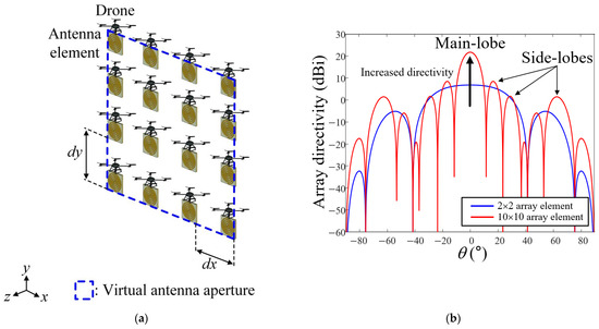
Figure 1.
Basic theory of the drone swarm systems: (a) geometry of the drone swarm system; (b) array directivity according to the number of elements.
Figure 2 illustrates the operational and electrical constraints in a planar drone swarm system. In the drone swarm, there are operational issues such as collisions between propellers of drones and downwash, as shown in Figure 2a. In particular, to detect signals operating in meter-wavelength bands, an antenna element with a large aperture size and heavy weight is mounted on the drone [18]. Heavy-lift drones [19,20] can be utilized in the drone swarm system to carry these heavy antenna elements, providing a payload capacity of up to 8.5 kg, as shown in Table 1. They can operate for 1 to 3 h at an altitude of 2000 m. Since these heavy-lift drones have a wide distance between propellers exceeding 1.5 m, a wider physical spacing between drones should be applied to the drone swarm system. To address the operational issues of the drone swarm, sufficient physical spacing between drones is required to be at least 0.2 m beyond their physical dimensions along both the x- and y-axes, as shown in Figure 2b [21,22,23]. When the drone swarm system employs heavy-lift drones, the required physical spacing becomes 1.7 m along the x-axis and 0.9 m along the y-axis. These physical spacings correspond to electrical spacings (antenna array spacings) of 1.7λ and 0.9λ at the highest operating frequency of 300 MHz, respectively. The large electrical spacing exceeding 0.9λ leads to SLL values moving toward 0 dB and the generation of grating-lobes from the array antenna perspective, as shown in Figure 2c [24,25]. These grating-lobes can lead to detection errors at high operating frequency bands. Therefore, an array configuration, which can provide sufficient array performance across multiple frequency bands while maintaining the physical spacing between drones, is required for the drone swarm system.
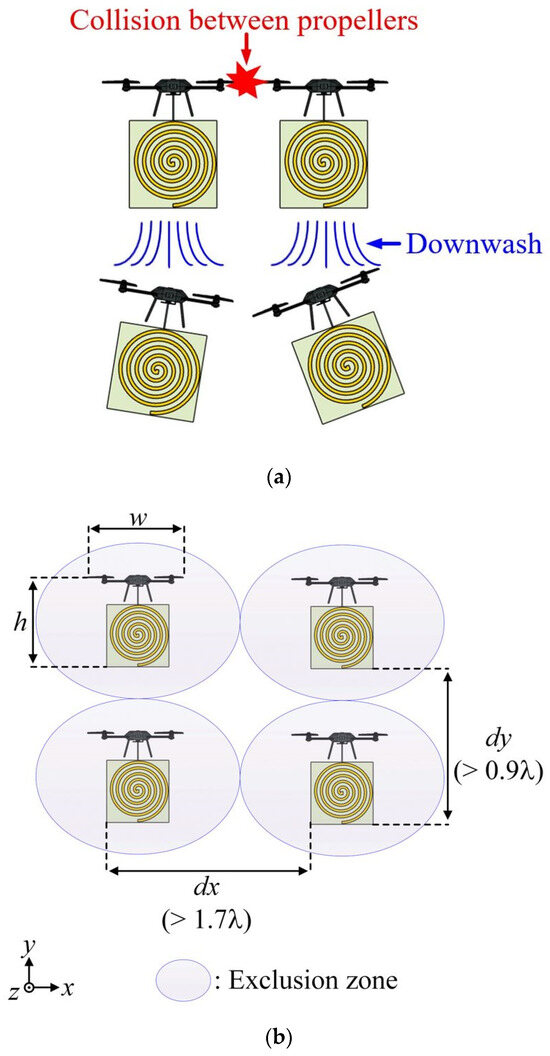
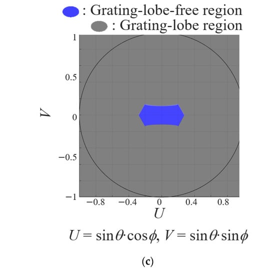
Figure 2.
Diagrams of operational and electrical constraints in the drone swarm system: (a) operational issue of the drone swarm system; (b) exclusion zone of drone swarm system; (c) grating-lobe-free region at a high frequency band.

Table 1.
Specifications of the commercial heavy-lift drones.
Figure 3 shows the configuration of the proposed 3-D volumetric self-complementary array. In the proposed system, multiple drones form two array layers separated along the boresight direction of the system, providing sufficient spacing between drones mounting an antenna element, as shown in Figure 3a. The antenna elements in one array layer are arranged in a complementary manner to fill empty spaces in the other layer, allowing the system to maximize the number of drones deployed within the aperture area, as shown in Figure 3b. In this configuration, since the elements in one layer compensate for the spacing in the other layer, the effective array spacing can be reduced on the virtual antenna aperture plane while maintaining the physical spacing between drones, as shown in Figure 3c. In particular, at an operating frequency of 300 MHz, the effective electrical spacing is reduced from 1.7λ and 0.9λ to 0.85λ and 0.45λ along the x- and y-axes, respectively. As a result, the proposed system can achieve a high array gain similar to that of conventional planar arrays with the same aperture size while maintaining low SLL values under the operational constraints of drone swarms. Moreover, since the antenna elements are arranged in a periodic array, the array gain of the proposed system can be easily enhanced by expanding the aperture size without additional optimization of antenna element positions, as shown in Figure 3d.
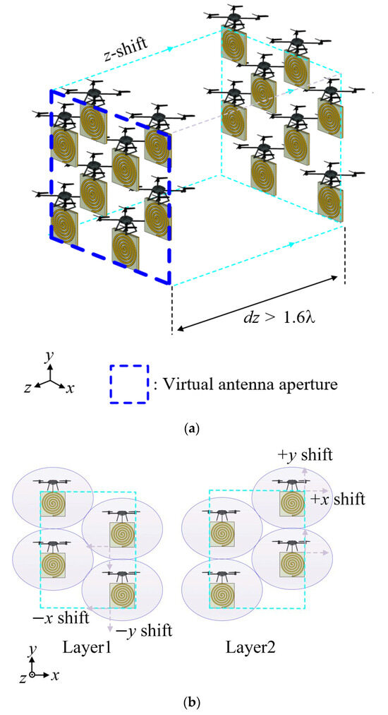
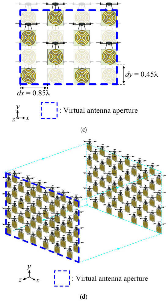
Figure 3.
Configuration of 3-D volumetric self-complementary array: (a) isometric view of the proposed drone swarm system; (b) self-complementary array layers of the proposed drone swarm system; (c) front view of the proposed drone swarm system; (d) isometric view of the fully extended drone swarm system.
Figure 4 illustrates the drone positions and array performance of the 2-D planar and proposed array configurations. To compare array performance, the two array configurations are expanded to a 12 × 8 array (M × N), and the SLL and grating-lobe-free regions are evaluated at 300 MHz. As shown in Figure 4a, due to the operational constraints of the drone swarm, the 2-D planar array has large array spacings of 1.7λ and 0.9λ along the x- and y-axes, respectively. This large array spacing results in grating-lobes with amplitudes comparable to that of the main-lobe in the radiation pattern, as shown in Figure 4b. In contrast, in the proposed array configuration, the effective electrical spacing is reduced to 0.85λ and 0.45λ along the x- and y-axes, respectively, as shown in Figure 4c. The array factor (AF) of the proposed system is calculated using Equations (1) and (2) [26]. When the antenna elements are placed in the front array layer, the AF of these elements is calculated using Equation (1). For the antenna elements deployed in the other array layer, Equation (2) is used to calculate the AF. The normalized amplitudes of the grating-lobes are reduced to −13.5 dB relative to the main-lobe, as shown in Figure 4d. In addition, in the proposed array configuration, the main-lobe can be steered over an azimuth angle range of −10° to +10°, and over an elevation angle range of −90° to +90° without generating grating-lobes, as shown in Figure 4e. These results indicate that the proposed drone swarm system can achieve an array gain comparable to that of 2-D planar array with the same aperture size, while providing improved electrical performance.
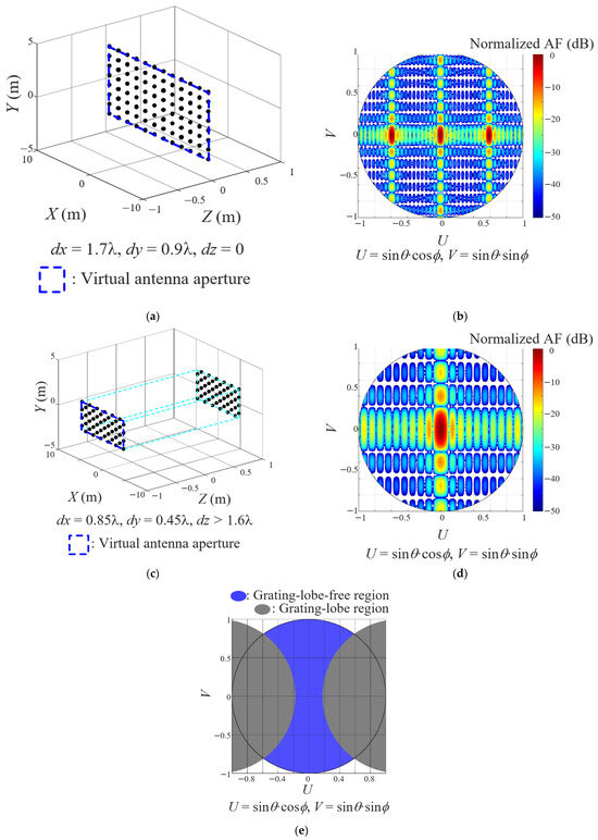
Figure 4.
Drone positions and array performance of the 2-D planar and proposed array configurations: (a) drone positions in the 2-D planar array configuration; (b) array factor of the 2-D planar array configuration; (c) drone positions in the proposed array configuration; (d) array factor of the proposed array configuration; (e) grating-lobe-free region of the proposed array configuration.
2.2. Geometry and Performance of a Broadband Characteristic Antenna Mounted on a Drone
Figure 5 illustrates the geometry of the broadband spiral antenna used in the proposed drone swarm system. The performance of the proposed array configuration is analyzed using a simulation in the VHF and UHF bands, assuming that broadband spiral antennas operating from 50 MHz to 300 MHz are mounted on the drones. The antenna element consists of a spiral arm of width w, which winds circularly Nturn times and gradually expands from an inner diameter D1 to an outer diameter D2, as shown in Figure 5a. When the antenna element is mounted on the drone, large-scale drones are required as the aperture size of the antenna element increases. In the drone swarm, the required physical spacing between drones also increases due to the large drone size, which degrades the array performance. To minimize the size of the antenna element and accommodate the limited payload capacity of the drones, the spiral arm is printed on a ceramic substrate with a high dielectric constant of εr [27]. To enhance the gain of the antenna element, cavities of height h2 are applied to the side faces of the substrate with height h1, as shown in Figure 5b [28]. The detailed geometrical parameters of the broadband spiral antenna are listed in Table 2.
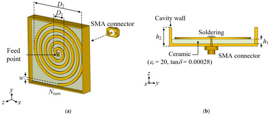
Figure 5.
Geometry of the broadband spiral antenna used in the drone swarm system: (a) isometric view; (b) side view.
Table 2.
Geometrical parameters of the broadband spiral antenna.
Figure 6 illustrates the simulated performance of the broadband spiral antenna. The blue and red solid lines indicate the simulated results of the antenna element without the drone (free space) and mounted on the drone, respectively. The spiral antenna has a reflection coefficient of −21.2 dB at the center frequency of 175 MHz. The average reflection coefficient from 50 MHz to 300 MHz is observed to be −14.5 dB, which is similar to the result without the drone, as illustrated in Figure 6a. As shown in Figure 6b–d, the maximum gains of the antenna are −13.7 dBi, −9.4 dBi, and −1.2 dBi at 100 MHz, 200 MHz, and 300 MHz, respectively. When this antenna element is mounted on a drone, the maximum gains are −11.8 dBi, −10.5 dBi, and −1.2 dBi, respectively. These results indicate that the spiral antenna provides broadband and directional radiation characteristics suitable for the multiple bands signal reception, even under platform-mounted conditions. Since both the reflection coefficients and radiation patterns are preserved after mounting on the drone platform, the antenna performance is not affected by the drone structure. To verify the feasibility of the proposed system, this antenna element is applied to the array configuration, and the array performance across multiple frequency bands, such as the array gain, SLL, and beam steering range, is investigated using the EM simulator CST.
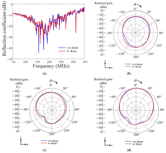
Figure 6.
Performances of the broadband spiral antenna: (a) reflection coefficients; (b) 2-D radiation patterns at 100 MHz; (c) 2-D radiation patterns at 200 MHz; (d) 2-D radiation patterns at 300 MHz.
Figure 7 shows the variation of array performance with respect to the array spacing in a 12 × 8 drone array configuration. In the proposed array configuration, as the array spacing along the z-axis increases, the effective array spacing along the x- and y-axes can be reduced. As shown in Figure 7a, when the array spacing along the z-axis exceeds 1.47 m, the effective array spacing along the x- and y-axes is reduced to 0.85 m and 0.45 m, respectively. This indicates that a z-axis array spacing greater than 1.47 m is required to sufficiently reduce the effective array spacing on the aperture plane. However, excessive separation along the z-axis can cause partial blockage of the antenna radiation patterns by adjacent drones, so the array spacing along the z-axis is adjusted to balance the array gain and SLL at 300 MHz, while maintaining array spacings along the x- and y-axes, as shown in Figure 7b. When the array spacing along the z-axis increases from 0 m to 2.5 m, the array gain decreases from 11.8 dBi to 9.1 dBi. In contrast, under the same conditions, the SLL decreases from 0 dB to −12.1 dB due to the reduced effective array spacings along the x- and y-axes. When the array spacing along the z-axis exceeds 1.6 m, the amplitude of the main-lobe decreases, and the SLL value correspondingly is raised. Thus, the z-axis array spacing exceeding 1.6 m, at which the proposed system achieves low SLL values while maintaining sufficient array gain, is selected for the proposed system.
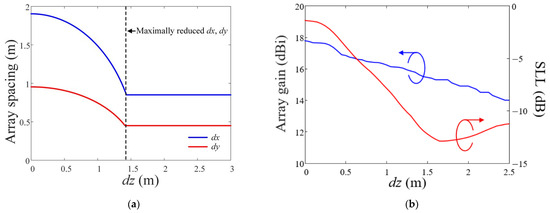
Figure 7.
Variation of array performance with respect to the array spacing: (a) variation of the array spacing on the xy-plane; (b) variation of array gain and SLL.
Figure 8 shows the 3-D radiation patterns according to the array configurations. Figure 8a–c presents the results for the planar array configuration, whereas Figure 8d–f shows the 3-D radiation patterns of the proposed array configuration. These results are obtained by the simulation when 96 antenna elements mounted on the drone are deployed in a 12 × 8 array. The radiation patterns of each antenna element are synthesized to obtain the array gain for the two configurations. Here, the array gains are determined by the single element pattern and the array directivity. To ensure a fair comparison, the minimum array spacing required to prevent operational issues of the drone swarm is applied to each array configuration. For the 2-D planar array configuration, wide array spacings of 1.7λ and 0.9λ along the x- and y-axes are employed, considering the physical dimensions of the drones and antennas. At the low frequency band of 100 MHz, the array gain and SLL are 4.18 dBi and −13.0 dB, respectively, as shown in Figure 8a. However, due to the large array spacing, the system exhibits SLLs of −6.2 dB and −1.4 dB at higher frequency bands of 200 MHz and 300 MHz, respectively, as shown in Figure 8b,c. In contrast, the proposed 3-D self-complementary configuration can reduce the effective array spacings to 0.85λ and 0.45λ along the x- and y- axes, respectively, while maintaining the same physical spacing between the drones. The array gains of the proposed system are 3.96 dBi, 6.40 dBi, and 15.3 dBi at 100 MHz, 200 MHz, and 300 MHz, respectively, and the SLLs are −13.0 dB, −12.7 dB, and −13.0 dB, as shown in Figure 8d–f. These results demonstrate that the proposed system achieves low SLL values using the 3-D volumetric self-complementary array configuration. In addition, to investigate the stability of the proposed drone swarm system, the performance degradation is investigated considering the position error of the heavy-lift drones, as shown in Figure 9. Since the heavy-lift drones [18,19] have a GPS and LIDAR accuracy of approximately 2 cm and 2.5 cm, the random position errors are set to a maximum of 2.5 cm along x-, y-, and z-axes. At a high frequency band of 300 MHz, the variation of the array directivity ranges from 0 dB to 0.2 dB, and the maximum variation of SLL is 1.2 dB. These results indicate that the drone swarm system can have low performance degradation by position errors of drones.

Figure 8.
3-D radiation patterns according to the array configurations: (a) 2-D planar array at 100 MHz; (b) 2-D planar array at 200 MHz; (c) 2-D planar array at 300 MHz; (d) proposed array at 100 MHz; (e) proposed array at 200 MHz; (f) proposed array at 300 MHz.
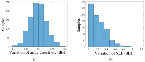
Figure 9.
Performance degradation by the position error of the drones at 300 MHz: (a) variation of the array directivity; (b) variation of the SLL.
Figure 10 shows the beam steering performance of the proposed drone swarm system. To evaluate the beam steering performance, the main-lobe is steered in both azimuth and elevation directions within ranges where grating-lobes do not occur. As shown in Figure 10a, at 100 MHz, when the main-lobe is steered from an azimuth angle of 0° to 45°, the array gain is maintained above 1.52 dBi, and the maximum SLL is −10.5 dB. As shown in Figure 10b, at the same frequency, when the main-lobe is steered from an elevation angle of 0° to 45°, the array gain remains above 1.21 dBi, and the SLL stays below −14.9 dB. Under the same steering condition, at 200 MHz, the main-lobe can be steered up to an azimuth angle of 30° and an elevation angle of 35° without grating-lobes, as shown in Figure 10c,d. In this case, the array gains at the azimuth angle of 30° and the elevation angle of 35° are 3.82 dBi and 3.75 dBi, respectively, while the SLLs are −13.2 dB and −12.1 dB. At the highest frequency band of 300 MHz, the proposed system can steer the main-lobe to an azimuth angle of 25° and an elevation angle of 30°, as shown in Figure 10e,f. When the main-lobe is steered to the maximum azimuth and elevation angles, the array gains are 13.6 dBi and 9.8 dBi, respectively, and the SLLs remain below −14.2 dB and −10.1 dB. These results indicate that the proposed system can scan a wide angular region without generating grating-lobes using the 3-D volumetric self-complementary array configuration.
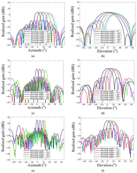
Figure 10.
Beam steering performance of the proposed system: (a) azimuth angle steering at 100 MHz; (b) elevation angle steering at 100 MHz; (c) azimuth angle steering at 200 MHz; (d) elevation angle steering at 200 MHz; (e) azimuth angle steering at 300 MHz; (f) elevation angle steering at 300 MHz.
Table 3 shows the performance comparison table between the 3-D aperiodic [14], 2-D planar, and proposed array configurations. To prevent the operational issues of the drone swarm, the previous study proposes the 3-D aperiodic array configuration, which achieves the array directivity of 20 dBi and SLL value of −9 dB at 1 GHz. However, since this array configuration applies the aperiodic array spacing, the SLL varies in accordance with the operating frequency, and additional optimization processes are required to expand array configuration. In contrast, the proposed system adopts a drone swarm design method using the 3-D self-complementary array configuration, which can reduce the effective electrical spacing between antenna elements while maintaining sufficient physical spacing between drones. Consequently, it can achieve high array directivity above 15.0 dBi and low SLL values below −12.7 dB from 100 MHz to 300 MHz. Since the system has a periodic array configuration, the drone swarm system can be easily expanded without additional optimization.
Table 3.
Comparison of the various drone swarm systems.
3. Detection Ranges of the Proposed SIGINT System
3.1. SIGINT Scenario of Systems Based on Various Applications
To investigate the advantages of the proposed system, the proposed drone swarm SIGINT system is evaluated in a practical SIGINT environment that considers terrain features, and the detection performance is compared with those of conventional ground-based and airborne SIGINT systems. In this SIGINT scenario, to evaluate performance under terrain-induced blockages, the systems are located at the center of the Korean Peninsula, which is characterized by mountainous terrain, and the received power at 300 MHz is evaluated up to 250 km, as shown in Figure 11a. Herein, the antenna gain and transmitted power of the unknown signal are assumed to be 0 dBi and 30 dBm (1 W), respectively, and the receiver sensitivity of the SIGINT systems is assumed to be a commercial value of −95 dBm [29]. The aperture sizes of the ground-based and airborne systems are 50 m2 (10 m × 5 m) and 8.5 m2 (5 m × 1.7 m), respectively, which represent typical aperture sizes of each system [30,31]. The proposed system has an aperture size of 30 m2 (10 m × 3 m), where 12 × 8 drones are arranged at spacings of 0.85 m and 0.45 m along the x- and y-axes, respectively. Based on these aperture sizes, the ground-based, airborne, and proposed systems have array gains of 19.1 dBi, 8.1 dBi, and 15.3 dBi, respectively. The ground-based system is positioned on a mountain with an altitude of 300 m, and the airborne system operates at 15,000 m. Since drones used for the proposed system can fly to 2000 m, the operating altitude of the proposed system is set to 2000 m. To analyze this SIGINT scenario, the path loss is calculated using the propagation EM simulator Advanced Refractive Effects Prediction System (AREPS) [32], which accounts for terrain-induced diffraction and tropospheric refraction effects. The terrain profile is extracted from digital elevation model (DEM) data provided by the Ministry of Land, Infrastructure and Transport of the Republic of Korea (MOLIT) [33]. Using this simulation, the path loss considering the propagation distance, system altitude, and terrain profile is obtained. The received power is calculated using Equation (3), which accounts for the transmitted power, antenna gains, path loss, and system loss [34]. The detection range is then defined as the maximum distance at which the received power exceeds the system sensitivity, as defined by Equation (4) [35]:
where Pr denotes the received power, Pt presents the transmitted power, Gt and Gr refer to the gains of the transmitting (signal sources) and receiving (antenna elements of the SIGINT system) antennas, respectively, Lpath is the path loss calculated by the AREPS simulator, Lsystem denotes a system loss of 10 dB accounting for practical implementation margins, including losses from cables, connectors, and calibration uncertainties [36], and Psensitivity is the sensitivity of the SIGINT system. The detailed parameters of the SIGINT systems, including antenna aperture sizes, operating altitudes, and receiving antenna gains, are listed in Table 4.
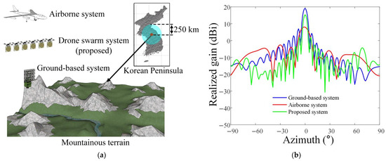
Figure 11.
SIGINT scenario of various systems: (a) environment of the SIGINT scenario; (b) 2-D radiation patterns of each system.
Table 4.
Parameters of the SIGINT systems.
3.2. Detection Ranges of Systems Based on Various Applications
Figure 12 shows the received power distribution of various SIGINT systems. The LOS of the ground-based system is blocked by terrain at approximately 50 km, which limits the detection range to 47.5 km despite the high array gain of 19.1 dBi at 300 MHz, as shown in Figure 12a. To overcome the LOS limitation by terrain, the airborne system operating at a high altitude of 15,000 m can be employed, and the LOS of the airborne system is not constrained by terrain, as shown in Figure 12b. However, since the array gain of the airborne system is limited to 8.1 dBi due to a small aperture size of 8.5 m2, the detection range is also limited to 115 km. In contrast, the proposed drone swarm system operates at a higher altitude of 2000 m than the ground-based system, and the array gain of the proposed system is 15.3 dBi, which is higher than that of the airborne system. Therefore, the proposed drone swarm system achieves an extended detection range of 150 km, as shown in Figure 12c. In addition, at other frequency bands of 100 MHz and 200 MHz, the detection ranges are observed to be 85.2 km and 101 km, when the array gains are 3.96 dBi and 6.40 dBi, respectively.
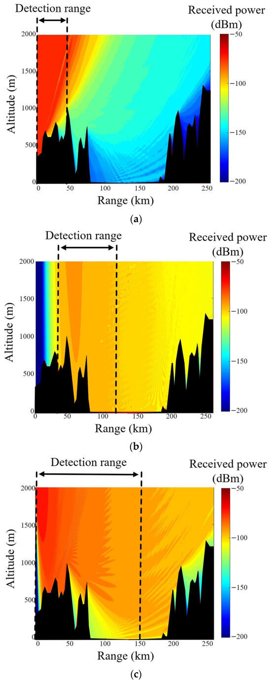
Figure 12.
Received power distributions of various SIGINT systems: (a) ground-based system; (b) airborne system; (c) drone swarm system.
Figure 13 shows the 2-D received power distributions of various SIGINT systems. The LOS of the ground-based system is limited by terrain and low altitude, resulting in a detection range of about 47.5 km. In contrast, since the airborne system operates at 15,000 m, the received power varies with the distance regardless of the terrain. However, the array gain of the airborne system is lower than that of the other systems, so the received power is lower than the system sensitivity of −95 dBm beyond a distance of 115 km. For the proposed system operating at 2000 m, terrain-induced blockage is significantly reduced compared to the ground-based system. In addition, the proposed system can form a larger aperture size than that of the airborne system, and the array gain of the proposed system also can be enhanced to a level higher than that of the airborne system. These results demonstrate that the proposed system provides an extended detection range of 150 km in practical SIGINT environments.
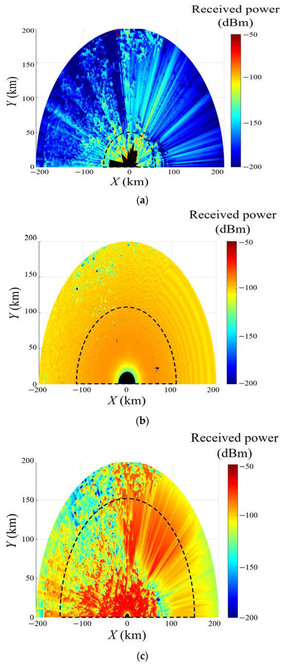
Figure 13.
2-D received power distributions of various SIGINT systems: (a) ground-based system; (b) airborne system; (c) drone swarm system.
4. Conclusions
In this paper, we proposed a SIGINT drone swarm system with a 3-D volumetric self-complementary array configuration. In the proposed system, multiple drones formed two array layers separated along the boresight direction of the system, providing sufficient spacing between drones mounting an antenna element. The antenna elements in one array layer were arranged in a complementary manner to fill empty spaces in the other layer, allowing the system to maximize the number of drones deployed within the aperture area. In the proposed array configuration, the effective electrical spacing at 300 MHz was reduced from 1.7λ and 0.9λ to 0.85λ and 0.45λ along the x- and y-axes, respectively. The array gains of the proposed system were 3.96 dBi, 6.40 dBi, and 15.3 dBi at 100 MHz, 200 MHz, and 300 MHz, respectively, while the SLLs were −13.0 dB, −12.7 dB, and −13.0 dB. Therefore, the proposed system achieved a high gain similar to that of conventional planar arrays while keeping low SLL values under the operational constraints of the drone swarm. In addition, the proposed drone swarm SIGINT system was evaluated in a practical SIGINT environment that considers terrain features, and the detection performance was compared with that of conventional ground-based and airborne SIGINT systems. In this SIGINT scenario, the proposed system achieved an extended detection range of 150 km than ground-based and airborne systems. These results demonstrated that the proposed system provided an extended detection range not only in terms of array performance but also in practical SIGINT environments.
Author Contributions
Conceptualization, E.-Y.Y., T.J., J.-Y.L. and H.C.; Formal analysis, E.-Y.Y., T.J. and H.C.; Investigation, E.-Y.Y. and T.J.; Methodology, E.-Y.Y., T.J., J.-Y.L. and H.C.; Project administration, T.J.; Resources, J.-Y.L. and H.C.; Software, E.-Y.Y. and T.J.; Supervision, H.C.; Validation, E.-Y.Y., T.J. and H.C.; Visualization, E.-Y.Y. and T.J.; Writing—original draft, E.-Y.Y. and T.J.; Writing—review and editing, E.-Y.Y., T.J., J.-Y.L. and H.C. All authors have read and agreed to the published version of the manuscript.
Funding
This paper was supported by Korea Institute for Advancement of Technology (KIAT) grant (P0028167) funded by the Korea Government (Ministry of Education).
Institutional Review Board Statement
Not applicable.
Informed Consent Statement
Not applicable.
Data Availability Statement
Data are contained within the article.
Conflicts of Interest
The authors declare no conflicts of interest.
References
- Wang, H.; Jonhson, J.T.; Baker, C.J. Spectrum Sharing between Communications and ATC Radar Systems. IET Radar Sonar Navig. 2017, 11, 994–1001. [Google Scholar] [CrossRef]
- Paul, B.; Chiriyath, A.R.; Bliss, D.W. Survey of RF Communications and Sensing Convergence Research. IEEE Access 2016, 5, 252–270. [Google Scholar] [CrossRef]
- Griffiths, H.; Cohen, L.; Watts, S.; Mokole, E.; Baker, C.; Wicks, M. Radar Spectrum Engineering and Management: Technical and Regulatory Issues. Proc. IEEE 2014, 103, 85–102. [Google Scholar] [CrossRef]
- Domenico, F.; Giulia, V.; Maria, U.; Alessandro, Z. Technologies for IMINT and SIGINT. In Proceedings of the IEEE International Workshop on Technologies for Defense and Security, Rome, Italy, 22 November 2023. [Google Scholar]
- Im, C.; Seo, W.; Park, S.; Kim, K.; Park, S.; Choo, H. Design of a Deployable Broadband Mesh Reflector Antenna for a SIGINT Satellite System Considering Surface Shape Deformation. Sensors 2024, 24, 384. [Google Scholar] [CrossRef] [PubMed]
- Celik, G.; Aitalieva, A.; Celebi, H.; Uysal, M. A Software Defined Radio Based Data Link Design for VHF Band Wireless Sensor Networks. Phys. Commun. 2018, 30, 167–178. [Google Scholar] [CrossRef]
- Qin, D.; Sun, B. VHF/UHF Wideband Slim Monopole Antenna with Distributed Matching Structures. Int. J. Antennas Propag. 2022, 2022, 3369422. [Google Scholar] [CrossRef]
- Pike, J. AN/FLR-9; Federation of American Scientists. Available online: https://irp.fas.org/program/collect/an-flr-9.htm (accessed on 21 July 2025).
- Soo, Q.-P.; Lim, S.-Y.; Chee, P.-S.; Lim, E.-H.; Yap, K.-M. Radio propagation modeling and measurement of uneven terrain model. Sci. Rep. 2025, 15, 28654. [Google Scholar] [CrossRef]
- Lee, J.-H.; Joo, J.-M.; Kim, K.; Lee, J.-H.; Park, Y.-J. Practical Consideration Factors to Design Array Configuration of Direction-Finding System for Airborne Signal Intelligence. Secur. Commun. Netw. 2018, 2018, 9185760. [Google Scholar] [CrossRef]
- Vivekanandan, J.; Ellis, S.; Tsai, P.; Loew, E.; Lee, W.-C.; Emmett, J.; Dixon, M.; Burghart, C.; Rauenbuehler, S. A wing pod-based millimeter wavelength airborne cloud radar. Geosci. Instrum. Method. Data Syst. 2015, 4, 161–176. [Google Scholar] [CrossRef]
- Harmer, S.W.; Novi, G.D. Distributed Antenna in Drone Swarms: A Feasibility Study. Drones 2023, 7, 126. [Google Scholar] [CrossRef]
- Preiss, J.A.; Honig, W.; Sukhatme, G.S.; Ayanian, N. Trajectory Planning for Quadrotor Swarms. IEEE Trans. Robot. 2018, 34, 856–869. [Google Scholar] [CrossRef]
- Diao, J. Unmanned Aerial Vehicles Swarm-Based Distributed Phased Arrays for Grating Lobe Mitigation and Collision Avoidance. IEEE Open J. Antennas Propag. 2022, 3, 1264–1272. [Google Scholar] [CrossRef]
- Dassault Systèmes. CST Studio. Available online: http://www.cst.com (accessed on 15 August 2025).
- Yeoh, Y.-S.; Min, K.-S. High-Gain Design of a 6 × 26 Slotted Waveguide Array Antenna with a Grid Cavity for Ku-Band Wave-Monitoring RADAR Systems. J. Electromagn. Eng. Sci. 2025, 25, 500–510. [Google Scholar] [CrossRef]
- Balanis, C.A. Antenna Theory: Analysis and Design, 3rd ed.; John Wiley & Sons: Hoboken, NJ, USA, 2005. [Google Scholar]
- Zhao, Y.; Li, Q.; Liu, X.; Wang, P.; Liao, D.; Jing, L.; Cheng, Y. A Window-Embedded Broadband Vehicle-Mounted Antenna for FM Broadcast Application Based on the Characteristic Mode Theory. Electronics 2026, 15, 103. [Google Scholar] [CrossRef]
- UAV Systems International/Aurelia Aerospace. Aurelia X8 Pro. Available online: https://uavsystemsinternational.com/products/aurelia-x8-pro (accessed on 15 August 2025).
- DJ Agriculture. DJI AGRAS T25. Available online: https://ag.dji.com/kr/t25 (accessed on 15 August 2025).
- Inan, A.T. CFD Analysis of Aerodynamic Characteristics in a Square-Shaped Swarm Formation of Four Quadcopter UAVs. Appl. Sci. 2024, 14, 6820. [Google Scholar] [CrossRef]
- Marek, D.; Biernacki, P.; Szyguła, J.; Domański, A.; Paszkuta, M.; Szczygieł, M.; Król, M.; Wojciechowski, K. Collision Avoidance Mechanism for Swarms of Drones. Sensors 2025, 25, 1141. [Google Scholar] [CrossRef]
- Dbouk, T.; Drikakis, D. Quadcopter drones swarm aeroacoustics. Phys. Fluids 2021, 33, 57112. [Google Scholar] [CrossRef]
- Zhu, Y.; Ma, W.; Wang, C.; Cao, W. Low Sidelobe Planar Electrically Large Sparse Array Antenna with Element Number Reduction Based on Genetic Algorithm. IET Microw. Antennas Propag. 2024, 18, 447–458. [Google Scholar] [CrossRef]
- Darwish, M.; Hassani, H.R. Wideband Transmitarray Antenna Based on Two-Layer Aperture-Coupled Metasurface Unit Cell. J. Electromagn. Eng. Sci. 2025, 25, 400–401. [Google Scholar] [CrossRef]
- Stark, L. Microwave Theory of Phased-array Antenna—A Review. IEEE 1974, 62, 1661–1701. [Google Scholar] [CrossRef]
- Han, K.; Swaminathan, M.; Pulugurtha, R.; Sharma, H.; Tummala, R.; Yang, S. Magneto-Dielectric Nanocomposite for Antenna Miniaturization and SAR Reduction. IEEE Antennas Wirel. Propag. Lett. 2015, 15, 72–75. [Google Scholar] [CrossRef]
- Jin, T.; Kang, E.; Ahn, M.; Ku, H.; Hong, S.; Choo, H. Design of a Receiving Array Antenna with a Trapezoidal Configuration Using Multiple Rectifier Circuits for Wide-Angle Reception. J. Electromagn. Eng. Sci. 2025, 25, 271–278. [Google Scholar] [CrossRef]
- ETSI EN 300 676-1 V1.5.2; Ground-Based VHF Hand-Held, Mobile and Fixed Radio Transmitters, Receivers and Transceivers for the VHF Aeronautical Mobile Service Using Amplitude Modulation; Part 1: Technical Characteristics and Methods of Measurement. European Telecommunications Standards Institute (ETSI): Sophia Antipolis, France, 2011.
- Techavijit, P.; Sukchalerm, P. Cost-Effective Satellite Ground Stations in Real-World Development for Space Classrooms. Aerospace 2025, 12, 105. [Google Scholar] [CrossRef]
- L3Harris Technologies. SE129 Series Antenna. Available online: https://www.l3harris.com/all-capabilities/se129-series-antenna (accessed on 12 November 2025).
- AREPS Documentation. Advanced Refractive Effects Prediction System (AREPS). Available online: https://scispace.com/pdf/advanced-refractive-effects-prediction-system-areps-kl6unwwbt4 (accessed on 12 November 2025).
- Ministry of Land, Infrastructure and Transport, Republic of Korea. National Geographic Information Institute (NGII). Available online: https://www.ngii.go.kr (accessed on 12 November 2025).
- Friis, H.T. A Note on a Simple Transmission Formula. Proc. IRE 1946, 34, 254–256. [Google Scholar] [CrossRef]
- Skolnik, M.I. Radar Handbook, 3rd ed.; McGraw-Hill: New York, NY, USA, 2008. [Google Scholar]
- Bruyne, J.D.; Joseph, W.; Plets, D.; Verloock, L.; Tanghe, E.; Martens, L. Comparison of the Link Budget with Experimental Performance of a WiMAX System. EURASIP J. Wirel. Commun. Netw. 2009, 2009, 237436. [Google Scholar] [CrossRef][Green Version]


Disclaimer/Publisher’s Note: The statements, opinions and data contained in all publications are solely those of the individual author(s) and contributor(s) and not of MDPI and/or the editor(s). MDPI and/or the editor(s) disclaim responsibility for any injury to people or property resulting from any ideas, methods, instructions or products referred to in the content. |
© 2026 by the authors. Licensee MDPI, Basel, Switzerland. This article is an open access article distributed under the terms and conditions of the Creative Commons Attribution (CC BY) license.