Abstract
Accident records from the actual operation of metal oxide arresters (MOAs) indicate that even MOA products that have passed standard tests still suffer from frequent damage. This phenomenon may be related to the fact that the current standards for MOA testing do not cover multiple stroke conditions. To investigate the damage mechanism of MOA under the effect of multiple strokes, this study conducts continuous current impulse tests on MOA and simultaneously performs finite element simulation analysis. A comparative analysis of the test and simulation results shows the following: The continuous impulse discharge process of multiple strokes causes instantaneous heat accumulation in the varistors, leading to a sudden temperature rise and inducing significant non-uniform thermal stress in the varistors; Under the condition of consistent total impulse energy, multiple strokes are more likely to cause damage to MOA varistors. Moreover, the higher the amplitude of the lightning current in multiple strokes, and the shorter the impulse interval, the higher the risk and degree of thermal damage to the MOA varistors; By analyzing the rate of change in the maximum thermal stress of the varistors, the significant effective range of the superposition effect of multiple strokes under different impulse intervals can be obtained.
1. Introduction
According to standards such as the Chinese standard GB/T 11032-2020, MOAs must undergo multiple rigorous tests, including tolerance characteristic tests, to ensure their reliability during actual operation [1,2]. However, operational data shows that some MOA products that passed standard tests still experience failures due to lightning strikes [3,4,5,6,7]. Existing research and standards mainly focus on single lightning impulses and multiple lightning strike conditions with long intervals, while studies on the testing and lightning resistance performance of MOA varistors under high-frequency continuous multiple stroke conditions remain limited. Current extensive lightning observation studies have found that over 70% of cloud-to-ground flashes in nature exhibit continuous return stroke phenomena. The Chinese standard GB/T 21714.1-2015 defines multiple strokes as a lightning flash consisting of an average of three to four strokes, with an interval of typically about 50 ms between two strokes [8]. Multiple strokes are characterized by short return stroke intervals and large energy release in a short period, which can accelerate MOA aging, even cause thermal breakdown, and thereby reduce protection performance and service life [9,10,11,12]. Although some MOAs have passed standard product tests at the factory stage, lightning damage still occurs, indicating that the tolerance performance of MOAs under multiple strokes is worthy of further research.
Scholars such as Darveniza conducted systematic experiments on ZnO arresters using six consecutive 8/20 μs current impulses. The results showed that obvious damage occurred to the MOAs under the action of continuous impulse currents [13]. Scholars like B.H. Lee studied the failure modes of varistors under continuous impulse voltages [14]. Zhang Chenli and others used a double-pulse impulse current generator to observe the breakdown and perforation status of resistor disks, and found that the aging and damage of the resistor disks were more severe [15]. Scholars including Bi Jieting discovered that after the MOA varistors were subjected to multiple consecutive impulse currents, their aging process accelerated and could develop into irreversible structural damage [16]. Zhang Chunlong and his team simulated the current waveform of multiple strokes in an experimental environment and analyzed the damage caused to MOAs [17]. Based on the finite element method, A.F. Andrade, Huang Lin, and other researchers conducted simulation analyses on the thermal effects of arresters during lightning strikes [18,19]. Li Pengfei and others found that the number of continuous impulse discharges and the interval time had a significant correlation with the aging rate of ZnO varistors, which would affect the failure and damage of the resistor disks [20]. Scholars such as Xu Wei carried out impulse experiments on ZnO varistors using a new type of multi-pulse lightning generator, and studied the degradation characteristics of ZnO varistors from aspects including their tolerance performance, electrical parameters, temperature distribution, and energy absorption [21]. Zhou Xiu and others found that multiple strokes would cause the temperature rise in MOAs, trigger changes in the characteristics and operating load of resistor disks, and significantly weaken their thermal stability [5]. Through experiments, Yuan Xiaohan and other scholars found that the dominant effect of multiple strokes on arrester varistors was the return stroke with the maximum amplitude in the lightning strike; the current amplitude that could be withstood under multiple strokes was lower than that under a single stroke, and the thermal stress caused by multiple strokes was smaller than that caused by a single stroke [22].
The above studies indicate that MOA failures are mostly related to the continuous action of multiple strokes, and multiple strokes tend to cause MOAs to continue to withstand the energy of subsequent lightning strikes before the energy of the first lightning strike is completely discharged. At present, most of the simulation technologies and equipment for multiple strokes can only generate continuous impulse currents with millisecond-level interval times. Some studies have explored the tolerance performance rules of MOA varistors under millisecond-level intervals, but there is a lack of continuous impulse tests at the microsecond level. In order to reflect the particularity of the thermal superposition effect in the MOA damage process, its tolerance performance should take the most severe working conditions into account, and it is necessary to explore the damage mechanism of varistors when the interval time of multiple strokes is at the microsecond level.
Therefore, considering the actual impact of multiple strokes on MOAs, this study explores the damage mechanism of multiple strokes on MOA varistors from aspects including continuous impulse current amplitude, the interval between two impulses, and the thermal stress superposition effect. The control variable method was adopted in this study; under the premise of ensuring consistent total impulse energy, two single-impulse discharge tests and continuous impulse discharge tests were conducted on MOA varistors, respectively. By comparing the damage characteristics of varistors during these two types of discharge processes, the temperature rise and thermal stress variation laws of varistors under multiple strokes were analyzed, and the damage process of varistors under different lightning current amplitudes and different interval conditions was explored. Meanwhile, a simulation study was carried out on the electro-thermal-mechanical multi-physics field coupling process of MOA varistors. By analyzing the change rate of the maximum stress of varistors, the intervals where the superposition effect is significant under different intervals were obtained.
2. Withstand Test of MOA Varistors Under Multiple Strokes
2.1. Withstand Test Platform
To investigate the process of MOA varistors under the effect of multiple strokes, the study established a continuous impulse test platform for MOA varistors. It used continuous impulse currents to simulate the multiple strokes process, and based on this platform, conducted continuous impulse discharge tests on the MOA varistors. The structure of the test platform is shown in Figure 1. It is mainly composed of a continuous impulse current generation device, an impulse current data monitoring device, and an MOA varistor fixing device. The continuous impulse current generator is capable of outputting double impulse current waves, whose amplitude and interval time can be independently adjusted and controlled. The device comprises two sets of independently operating impulse current generators (ICGs), a timing control module, a triggering device, and an operation control unit. Both ICG1 and ICG2 are equipped with dedicated charging/discharging and triggering circuits. The parameters of the wave-regulating inductors and resistors in the device can be adjusted as needed to output waveforms with different steepness. The high-precision time-delay control unit is the core component of the continuous impulse current generator. Unlike traditional devices triggered by electrical signals, this control unit is connected to an electric spark trigger via an optical fiber transmission link, enabling time-delay regulation within the range of 0~500 ms with a maximum control precision of 0.1 μs. After both ICG1 and ICG2 complete their charging processes, setting different time-delay parameters allows them to trigger discharge at specified different times.
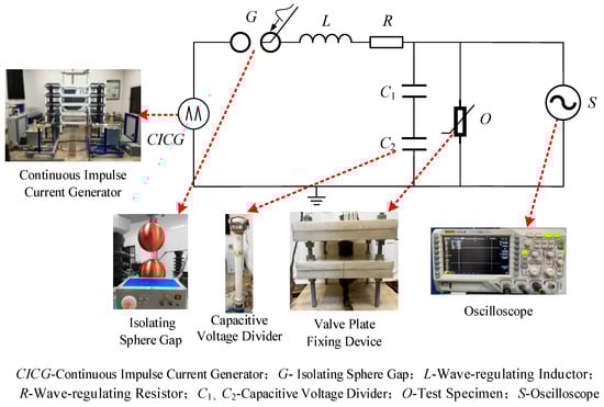
Figure 1.
Test platform structure diagram.
During the test, the high impedance of the varistor causes the two impulse current generators to not be completely independent. When ICG1 discharges, it causes a rapid rise in electrode potential, which in turn interferes with the insulation performance of the sphere gap in ICG2. This can lead to an unexpected breakdown of ICG2, resulting in the unintended simultaneous operation of the two sets of impulse current generators, and the interval time between them is difficult to control. To solve this problem, an additional pair of controllable trigger isolation sphere gaps was added to the discharge circuit of ICG2. By adjusting the gap distance of the sphere gap to an appropriate value, effective blocking of the counterattack voltage can be achieved. The impulse breakdown field strength of air is affected by various parameters such as humidity and electric field distribution uniformity, with a common range of 20~30 kV/cm. The relationship between the breakdown distance and the discharge voltage conforms to
where d is the breakdown distance (cm); U is the discharge voltage (kV); E1 is the breakdown field strength (kV/cm); and εt is the adjustment constant. The reference value of E1 is 25 kV/cm. The sphere gap distance is determined according to the discharge voltage of ICG1. Since the sphere gap adopts an electric spark triggering method, an adjustment margin of 6~8 mm needs to be added to this distance, based on actual debugging experience, and slightly adjusted according to the test environment conditions to ensure the isolation effect. During the test, trigger pulses are simultaneously sent to the sphere gaps of the two impulse current generators to allow the ICG2 circuit to conduct smoothly, thereby stably generating continuous impulse current waveforms. Using high-precision time-delay control and gap isolation technology, the continuous impulse current generator can output waveforms with specific interval times, and its control precision can reach the microsecond level, providing support for conducting impulse tests with microsecond-level interval times.
The zinc oxide (ZnO) varistors adopted in this study use high-purity ZnO powder as the matrix phase, doped with metal oxides including Bi2O3, Sb2O3, Co2O3, MnO2, and Cr2O3. The preparation process follows the traditional sintering technology, undergoing core procedures such as batching and ball milling, granulation and forming, binder removal and sintering, grinding and polishing, and silver electrode sintering. The core performance indicators of the prepared varistors, such as the nonlinear coefficient and DC reference voltage, all meet the requirements specified in the standards.
2.2. Withstand Test Scheme
In practical operation, MOAs are required to withstand multiple instances of multiple strokes. Meanwhile, repeated impulse tests specified in current standards generally adopt two or three impulses as the benchmark [1,2]. The rationale for this setting is as follows: three consecutive impulses can not only simulate the typical scenario where arresters are subjected to multiple strokes within a short period in actual operation, but also balance the effectiveness and operability of the test through a reasonable number of impulses. Therefore, three consecutive impulse discharges are employed as one test group in this study. Each impulse interval is 30 min to ensure the test sample is fully cooled to room temperature. The test employs 8/20 μs continuous impulse currents with intervals ranging from tens of microseconds to tens of milliseconds. The test procedure is as follows:
- (1)
- Measure and record the initial temperature and key electrical parameters of the test sample’s varistor, and take appearance photos.
- (2)
- Apply a continuous impulse current to the varistor and record its residual voltage waveform. After the impulse, if the residual voltage waveform is normal and there is no visible damage to the varistor’s appearance, conduct the next continuous impulse discharge after 30 min. Repeat this process until three times are completed.
- (3)
- If after any impulse, the residual voltage waveform of the varistor is abnormal, or the varistor suffers appearance damage such as cracking or flashover, terminate the test and determine the varistor as damaged.
- (4)
- After completing all three consecutive impulse discharges, measure the DC parameters of the test sample again and take photos of the varistor’s appearance. Synthesize all data to finally judge whether the varistor is damaged.
The Chinese standard GB/T 11032-2020 specifies the qualification criteria for metal oxide arresters (MOAs). The 1 mA DC reference voltage and the leakage current measured at 75% of the DC reference voltage are the core parameters for evaluating MOA performance [1]. According to the standard requirements, the residual voltage variation in MOA components under the nominal discharge current before and after the test shall not exceed ±5%, the variation rate of the DC reference voltage shall not exceed 5%, and the leakage current variation measured at 75% of the DC reference voltage shall not be greater than 20 μA [1,2]. After the test, a DC parameter tester for zinc oxide arresters is used to measure the 1 mA DC reference voltage (U1mA) of the MOA varistor and the leakage current (I0.75U) at 0.75 times the DC reference voltage. An infrared thermal imager is used to measure the surface temperature of the varistor to determine if the MOA varistor is damaged. Figure 2 shows the test sample temperature measurement device. The DC parameter tester for zinc oxide arresters can detect internal defects in MOAs rated at 10 kV and below. It is capable of measuring the varistor’s 1 mA DC reference voltage (U1mA) and leakage current at 0.75 U1mA. The voltage measurement range is 0~30 kV with a resolution of 0.1 kV, and the current measurement range is 0~1000 μA with a resolution of 0.5 μA. Measurement results can be read intuitively. The infrared thermal imager can detect the surface temperature of objects and display the temperature distribution as a visual thermal image with different colors. Through the thermal image, high-temperature points can be located, and the maximum and minimum temperatures within the measurement area can be displayed intuitively.
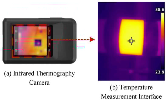
Figure 2.
Test sample temperature measuring device.
3. Finite Element Model of MOA Varistors
3.1. Numerical Modeling of MOA Varistors Under Multiple Strokes
During a lightning strike, an instantaneous large current passes through the MOA varistor, causing its temperature to rise sharply. This triggers rapid expansion inside the material, generating non-uniform thermal stress. Once the thermal stress exceeds the elastic limit of the varistor, it will lead to structural deformation and degradation of the varistor. Additionally, the accumulation of thermal stress is likely to induce local cracks in the varistor [23,24]. Therefore, to explore the stress variation law of MOA varistors under multiple strokes, finite element simulation is used to simulate the effect of multiple strokes on MOA varistors. The process of MOA varistor cracking and damage caused by multiple strokes mainly involves the interaction of current, heat transfer, and structural mechanics. When constructing the model, simplified forms are considered to optimize the modeling:
- Simplification of the Heat Dissipation Process: Adoption of Equivalent Heat Flux Boundary Conditions. In the analysis of lightning strike processes ranging from microseconds to milliseconds, transient heat conduction inside the varistor dominates heat transfer, while convective and radiative heat dissipation between the disk surface and air are relatively secondary. The use of equivalent heat flux boundary conditions to simulate surface heat dissipation can greatly simplify the model and avoid complex fluid–solid conjugate heat transfer calculations, which constitutes one of the standard practices in engineering simulation.
- Simplification of External Mechanical Loads: Exclusion of Wind Load and Self-Weight. The multiple strokes on the MOA varistor is a typical dynamic impact process. The primary driving force causing varistor damage is the thermal stress induced by rapid uneven heating, which typically reaches the order of hundreds of megapascals. This magnitude is generally much higher than that of static mechanical stresses generated by manufacturing residual stress, self-weight, or steady-state wind pressure. In contrast, the stress level caused by the self-weight of a single varistor is usually on the kilopascal scale, differing by several orders of magnitude from thermal stress. Therefore, neglecting these static or quasi-static loads can significantly reduce modeling complexity without compromising the simulation accuracy of thermal stress evolution in the model.
The coupling of the electrico-thermal-mechanical fields can be described from two levels: the first is electrical–thermal coupling, which refers to the interaction between current distribution and the temperature field; the second is thermal–mechanical coupling, which refers to the interaction between thermal expansion caused by temperature changes and the stress field.
According to Joule’s Law, when the impulse current in the current field flows through the varistor, Joule heat is generated, which serves as the volumetric heat source of the temperature field. In this process, there is a strong coupling between the electric field and the thermal field through Joule heat, and the coupling effect equation is as follows:
where ρ is the material density (kg/m3); C0 is the specific heat capacity at constant pressure [J/(kg∙K)]; u is the flow field velocity (m/s); ∇ denotes the gradient operator; T0 is the temperature (K); k is the thermal conductivity [W/(m∙K)]; Q0 is the heat source per unit volume generated by current (A/m3); J is the current density (A/m2); and E is the electric field strength (V/m).
When the temperature of the varistor rises instantaneously, it causes uneven thermal expansion. When thermal expansion is constrained by the varistor itself or external factors, thermal stress is generated. In this process, there is a strong coupling between the thermal field and the mechanical field through thermal expansion. The analysis of the thermal-mechanical coupling effect is mainly based on the linear thermal stress theory, and the coupling effect equation is as follows:
where εV is the thermal strain of the varistor; α is the thermal expansion coefficient (1/K); T2 and Tref are the temperature and reference temperature (K).
Boundary Condition Settings:
- Electrical Boundary Conditions
Electrode Configuration: The upper and lower surfaces of the varistor are defined as electrode boundaries to simulate the contact state between the varistor and electrodes in actual operation.
Current Waveform: The impulse current waveform is strictly set to 8/20 μs, which is fully consistent with the output waveform of the experimental platform, ensuring the consistency of working conditions between simulation and experiment.
- 2.
- Thermal Boundary Conditions
Heat Conduction: The thermal conductivity of the zinc oxide varistor is defined as a temperature-dependent parameter with a value range of k = 15∼25 W/(m⋅K), so as to match the heat transfer characteristics of the material at different temperatures.
Convective Heat Transfer: A natural convection boundary condition is applied to the surface of the varistor, with the convective heat transfer coefficient set as h = 10 W/(m2⋅K).
Thermal Radiation: The thermal radiation effect is considered, and the ambient temperature is set to 25 °C.
- 3.
- Mechanical Boundary Conditions
A fixed-free constraint is adopted: the lower surface of the varistor is set as a fixed constraint (with zero displacement), and the upper surface is set as a free boundary, which simulates the actual installation state of the varistor in the MOA.
3.2. Finite Element Model and Parameter Settings
This study relies on the COMSOL6.2 simulation software to establish a finite element model for the MOA varistor. The model has a radius of 24 mm and a height of 28 mm, as shown in Figure 3. The model mesh adopts the free triangular type. Local refinement is implemented in regions with high curvature, while relatively sparse division is applied in more regular regions. The analysis of the mesh generation quality of the varistor is shown in Figure 3b. After the geometric model is built, the material is set to zinc oxide (ZnO), and the corresponding parameters are configured. Table 1 presents the main material parameters of the varistor model. The material properties of ZnO varistors exhibit a significant temperature dependence: electrically, an increase in temperature induces an exponential growth in electrical conductivity, leading to a rise in leakage current; thermally, the thermal conductivity decreases with increasing temperature, exacerbating internal heat accumulation and temperature gradients; mechanically, the elastic modulus decreases as temperature rises, while the coefficient of thermal expansion increases slightly. In this study, these temperature-dependent properties have been incorporated into the electro-thermal-mechanical multi-field coupling model, ensuring that the simulation results are consistent with actual operating conditions.
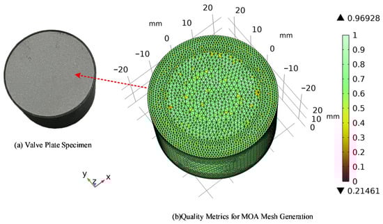
Figure 3.
Zinc oxide surge arrester varistor.

Table 1.
MOA varistor model parameters.
The electrical conductivity of the MOA varistor exhibits significant nonlinear characteristics, and its value changes dynamically with the amplitude, waveform, and action time of the impulse current. Under the action of the impulse current, its electrical conductivity increases instantaneously; however, in the low electric field region, the electrical conductivity is extremely low, showing insulator properties [25]. Therefore, the electrical conductivity of the varistor is set in the form of an interpolation function based on the test parameters, and Table 2 provides the interpolation functions of the varistor in the main nonlinear regions. In this study, a current pulse with an 8/20 μs waveform is used to simulate the lightning current.
Table 2.
Interpolation Function Table of Conductivity in the Main Nonlinear Region of ZnO Varistors.
4. Damage Condition and Cause Analysis of Varistors Under Multiple Strokes
4.1. Analysis of Withstand Test Results
The model of the selected MOA varistor is shown in Table 3. Since the MOA varistor has no pins or electrodes, to ensure stable wiring during the impulse test, the varistor is placed between customized varistor fixture fixing devices. This device can stabilize the varistor at the center position, and electrodes are led out from its upper and lower ends to connect wires. The test is carried out in accordance with the above test scheme. The impulse current is applied to both ends of the test sample. A capacitor divider, a Rogowski coil and an oscilloscope are used to measure and record the impulse current and the residual voltage of the test sample in real time. The ambient temperature is 25 °C. The specified residual voltage of the varistor is calculated according to the following formula:
where kr-max is the maximum voltage ratio of the varistor; Uref is the DC reference voltage of the varistor (kV), taken as 7.2 kV. The calculated specified residual voltage of the varistor is 12.67 kV.
Table 3.
Main parameters of MOA varistor.
4.1.1. Comparative Analysis of Single-Impulse and Continuous Impulse Discharge Results
To ensure the same lightning energy as applied in continuous impulse discharge, an 8/20 μs impulse current was used in the single-impulse test. Each varistor was subjected to two impulse currents with an interval of 5 min between the two impulses. Nine varistors from the same batch were selected and numbered D1 to D9 in sequence. The results of the single-impulse test are shown in Table 4, where varistors D1 to D3 and D6 remained undamaged. The results indicate that under the action of two nominal discharge currents, the varistors can still maintain structural integrity and normal operating performance. In addition, the greater the amplitude of the impulse current, the more likely the varistors are to be damaged.
Table 4.
Test results of single impact with different current amplitudes.
To investigate the effect of multiple strokes amplitude on the damage characteristics of varistors, continuous impulse discharge tests were conducted by changing the impulse current amplitude while keeping the impulse interval time constant. Twelve varistors from the same batch were selected and numbered F1 to F12 in sequence. The interval time of continuous impulse discharge was set to 30 ms, and the current amplitudes were 0.8Ib, Ib, 1.2Ib, and 1.4Ib, respectively. The test results are shown in Table 5. Under the nominal discharge current of 5 kA, all three groups of varistors (D1 to D3) under single-impulse action remained undamaged, while all three groups of varistors (F4 to F6) under continuous impulse discharge were damaged. It can be seen from this that multiple strokes amplify the damage effect of current on varistors—even if the current amplitude does not exceed the tolerance range under single-impulse, the heat superposition caused by multiple strokes will still lead to the failure of varistors.
Table 5.
Test results of continuous impulse impact discharge tests with different current amplitudes.
4.1.2. The Effect of Multiple Strokes Current Amplitude on Varistors
The results of continuous impulse discharge tests with different amplitudes show that the greater the amplitude of the continuous impulse current, the higher the temperature rise in the varistors, and there are significant differences in the appearance state of the varistors under different current amplitudes: Varistors F4 to F12 were all damaged. Among them, varistors F4, F7, and F10 to F12 showed obvious appearance cracking after the test, and the cracking parts were mainly concentrated at the edge of the varistor and the circumference of the bottom surface, as shown in Table 6. The rest of the varistors had intact appearances without damage such as cracks or cracks. Further analysis combined with the current amplitude gradient shows that the amplitude of multiple stroke currents has a significant impact on the damage degree of the varistors, and the damage degree shows an obvious intensifying trend with the increase in current amplitude: when the current amplitude is 1.4Ib, all the varistors involved in the test were blown up; when the current amplitude is 0.8Ib, none of the varistors showed appearance damage, and all passed the DC parameter test verification. Their key DC parameters met the requirements, indicating that the varistors still had normal working performance under this amplitude.
Table 6.
Varistors cracked during the test.
4.1.3. The Effect of Impulse Interval Time on Varistors
After clarifying the effect of the current amplitude on the damage characteristics of varistors, this study further explored the effect of multiple strokes’ interval time on the damage characteristics of varistors using the control variable method. The amplitude of the impulse current was kept constant, while the impulse interval time was changed to conduct continuous impulse discharge tests. Observation data indicate that the time intervals of multiple strokes mostly range from 60 ms to 90 ms, with the minimum interval being as short as tens of microseconds [26]. Additionally, scholars such as Ballarotti et al. from Brazil conducted lightning observation using high-speed cameras, and the recorded time intervals of multiple strokes ranged from 31 μs to 782 ms [27]. Therefore, the selection of time intervals including 100 μs, 300 μs, 800 μs, 10 ms, 30 ms, 60 ms, 100 ms, and 200 ms can cover the main intervals of natural multiple strokes.
Twelve varistors from the same batch were selected and numbered G1 to G12 in sequence. The current amplitude was set to Ib, and the interval times of continuous impulse discharge were 100 μs, 300 μs, 60 ms, and 100 ms, respectively. The test results are shown in Table 7. The data error of the test varistors is shown in the Figure 4, and the error is within a reasonable range. Among the 12 varistors involved in the test, only varistor G10 remained undamaged, and its residual voltage change rate and main DC parameters all met the requirements. The results indicate that the shorter the interval time, the higher the temperature rise in the varistor, and the greater the degree of damage.
Table 7.
Test results of continuous impulse discharge tests with different interval times.
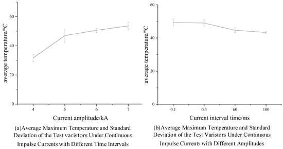
Figure 4.
Data Reliability of Test Samples.
4.2. Stress Variation of Varistors Under Multiple Strokes
Based on the finite element model mentioned above, a simulation test of MOA varistors under multiple strokes was conducted to obtain the temperature and stress distribution of the varistors after each impulse. Combined with their temperature rise characteristics, the influence law of different impulse conditions on the thermal stress of the varistors was explored. The internal thermal stress of the varistor can be calculated by the following formula:
where E is Young’s modulus (Pa); α is the coefficient of thermal expansion (1/K); μ is Poisson’s ratio; ΔT1 and ΔT2 are the temperature rises in the varistor (K).
Under the conditions of a fixed current waveform and an impulse interval of 30 ms, continuous impulse currents with different amplitudes are applied to the MOA varistor. The Ib current waveform is defined as an 8/20 μs impulse current with an amplitude of 5 kA. The maximum temperature and maximum stress of the varistor obtained when the current amplitude is set to 0.8Ib, Ib, 1.2Ib, and 1.4Ib, respectively, are shown in Table 8. Among them, the stress distribution of the varistor under the action of Ib is presented in Figure 5. Table 9 and Figure 6 record the maximum temperature and maximum stress of the varistor under the conditions of the same amplitude but different interval times. It can be observed that the shorter the interval time, the higher the temperature rise in the varistor and the greater the stress. The stress difference Δfh under the action of continuous impulse currents with interval times of 100 μs and 200 ms can reach 1.749 × 10⁸ Pa.
Table 8.
Maximum temperature and maximum stress of the varistor under continuous impulse currents with different amplitudes.
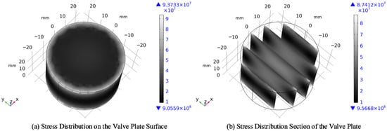
Figure 5.
Stress distribution of the varistor under continuous impulse current with amplitude Ibf.
Table 9.
Maximum temperature and maximum stress of the varistor under continuous impulse currents with different interval times.
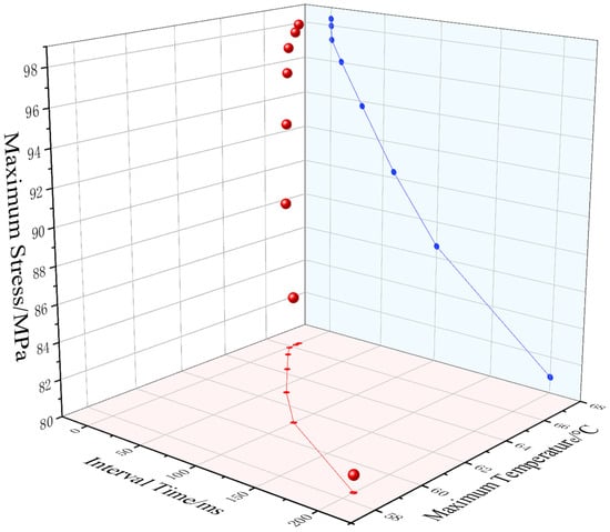
Figure 6.
Maximum temperature and maximum stress of the varistor under continuous impulse currents with different interval times.
According to the three-dimensional stress distribution of the varistor, the stress distribution of the varistor shows significant inhomogeneity. Due to the synergistic effect of geometric constraints and load transfer, obvious stress concentration occurs in the top and bottom circumferential edges and side edge regions of the varistor, which is consistent with the cracking location of the varistor in the test. The peak stress can reach 9.37 × 10⁷ Pa, while the stress level in the top, center, and middle side regions is relatively low, with the minimum value being approximately 9.05 × 10⁶ Pa. This distribution law of high stress at the edges and low stress in the middle is closely related to the mechanical boundary effect of the cylindrical structure, as the constraint conditions at the edges are more likely to cause stress concentration.
Finite element simulation results show that under the action of multiple strokes, the thermal stress of the varistor is closely related to the lightning strike amplitude and interval time. The higher the lightning strike amplitude, the greater the energy injected into the varistor, which enhances the Joule heating effect. This not only causes a sharp rise in the local temperature of the varistor but also leads to a significant increase in thermal stress induced by uneven thermal expansion. In combination with the maximum stress change rate in Table 9, the absolute value of the maximum stress change rate of the varistor under microsecond-order (100~800 μs) interval times is greater than 1500 MPa/s, where the varistor stress is jointly affected by the cumulative effect and superposition effect. For millisecond-order (0.8~200 ms) interval times, the absolute value of the maximum stress change rate is less than 130 MPa/s, and the varistor stress is mainly dominated by the cumulative effect, and the impact of the superposition effect on the varistor stress can be neglected. Overall, the shorter the lightning strike interval, especially when it reaches the microsecond level, the internal heat of the varistor fails to dissipate fully through thermal conduction and convection in time. This causes thermal stress to accumulate several times in the circumferential area of the varistor’s outer ring, forming a heat superposition effect, which in turn keeps the temperature continuously at a high level and leads to greater thermal stress. This short-term superposition effect is likely to cause cracks or structural degradation of the varistor, ultimately increasing the risk of cracking.
The interval of subsequent strokes in multiple strokes is shorter than the heat dissipation cycle of the varistor. Sustained heat accumulation leads to a rise in temperature, which in turn increases the carrier concentration and mobility at the grain boundaries, forming a positive feedback loop of “temperature rise—increased conductivity—more heat generation”. Prolonged temperature elevation weakens the grain boundary potential barrier, resulting in the degradation of the varistor’s nonlinear characteristics and the simultaneous induction of thermal stress concentration. When the thermal stress exceeds the fracture strength of the material, cracks initiate at vulnerable locations such as the varistor edges, and the protective function is ultimately lost due to crack propagation or thermal breakdown.
In general, the shorter the lightning strike interval (down to the microsecond level), the less time the internal heat of the varistor has to dissipate sufficiently through heat conduction and convection. This causes thermal stress to accumulate repeatedly in the circumferential region of the varistor outer ring, creating a heat superposition effect that maintains the temperature at a persistently high level and generates greater thermal stress. Such short-term superposition effect tends to induce cracking or structural degradation of the varistor, ultimately increasing the risk of bursting.
5. Conclusions
In this study, the control variable method was adopted to conduct continuous impulse tests and two single-impulse discharge tests on MOA varistors. The damage characteristics of the varistors were compared, the variation of thermal stress and their damage processes were analyzed, and electro-thermal-mechanical multi-physics field coupling simulation was performed to explore the interval where the superposition effect is significant under different impulse interval times. Furthermore, based on the extreme service conditions of MOAs in actual operation, and with the most severe lightning withstand conditions endured by varistors as the core research premise, this study systematically investigates the influence laws of multiple strokes with microsecond-level intervals on the damage mechanism of MOA varistors. From the perspective of applicability, the core working principle is consistent between MOAs of higher voltage classes and medium-voltage MOAs—both rely on the nonlinear conductivity characteristics of ZnO varistors to perform overvoltage limitation functions. The response mechanism of MOA varistors under multiple strokes elucidated in this research can provide a theoretical reference for the damage analysis of products with higher voltage classes. This study not only fills the research gap in microsecond-level multiple stroke conditions within current standards, but also offers a solid theoretical basis and engineering practice reference for the structural optimization design, withstand performance improvement of MOAs, as well as the revision and refinement of industry lightning protection test standards, thereby facilitating the enhancement of the operational reliability of power systems in lightning-prone areas. The following conclusions are drawn:
- (1)
- Under the action of continuous impulse current, the MOA varistor exhibits an obvious heat superposition effect. Heat superposition causes the varistor to heat up rapidly, which in turn induces thermal expansion of the varistor material. Short-term thermal expansion generates inhomogeneous thermal stress inside the varistor, with stress concentrating at the circumferential edges of the varistor. Under the action of continuous impulse current with the amplitude of the nominal discharge current, the maximum thermal stress of the varistor can reach 9.373 × 10⁷ Pa. When the thermal stress exceeds the fracture toughness limit of the varistor, it will eventually lead to varistor cracking.
- (2)
- Under the condition of consistent total impulse energy, continuous impulse current is more likely to cause thermal damage to MOA varistors than two single-impulse currents. When the amplitude is equal to the nominal discharge current, the average maximum temperature of the varistor after the action of two single-impulse currents is 30 °C, and the residual voltage change rate is less than 3%. In contrast, the average maximum temperature of the varistor after the action of continuous impulse current is 47 °C, and the residual voltage change rate exceeds 10%. Under the action of continuous impulse current, the heat generated by the previous impulse in the varistor has not dissipated, and the heat brought by subsequent impulses continues to superimpose, resulting in the failure of effective heat release inside the varistor in an extremely short time. This forms a superposition effect, which is more likely to increase the risk of varistor damage.
- (3)
- The damage of MOA varistors caused by continuous impulse current is affected by the amplitude of the continuous impulse current and the impulse interval time: the higher the amplitude of the impulse current, the greater the energy density, and the more likely the varistor is to suffer more severe thermal damage; the shorter the interval time, the more residual heat from the previous lightning strike, the more significant the superposition effect with the heat from subsequent lightning strikes, and the more likely the varistor is to be damaged. The interval time of continuous impulse current affects the superposition effect. By analyzing the maximum stress change rate of the varistor, the intervals where the superposition effect is significant under different interval times can be obtained: When the interval time is 100~800 μs, the absolute value of the maximum stress change rate of the varistor is greater than 1500 MPa/s, and the varistor stress is affected by the combined action of the cumulative effect and the superposition effect; when the interval time is more than 800 μs, the absolute value of the maximum stress change rate of the varistor is less than 130 MPa/s, and the varistor stress is mainly dominated by the cumulative effect. It can be seen from this that an interval time of 1 ms (close to 0.8 ms) can be used as the critical interval time for the change in MOA damage mechanism.
Author Contributions
T.Y.: Conceptualization, Data curation, Formal analysis, Investigation, Methodology, Project administration, Funding acquisition, Resources, Validation, Visualization, Writing—original draft, Writing—review and editing. D.G.: Data curation, Investigation, Methodology, Software, Validation, Visualization, Writing—original draft, Writing—review and editing. S.C.: Formal analysis, Investigation, Methodology. Z.Z.: Formal analysis, Investigation, Methodology. All authors have read and agreed to the published version of the manuscript.
Funding
This research received no external funding.
Data Availability Statement
The raw data supporting the conclusions of this article will be made available by the authors on request.
Acknowledgments
This work was supported by the Science and Technology Project of State Grid Corporation. We also sincerely acknowledge Yongli Yi for his contributions to this paper in terms of formal analysis and funding acquisition.
Conflicts of Interest
The authors declare no conflicts of interest.
References
- GB/T 11032-2020; AC Metal-Oxide Surge Arresters Without Gaps. State Administration for Market Regulation: Beijing, China, 2020.
- DL/T 815-2021; Composite-Housed Metal-Oxide Surge Arresters for AC Transmission Lines. Electric Power Industry of China: Beijing, China, 2021.
- Li, P.; Xiao, P.; Qu, Y.Y.; Wang, Y.; Pu, Z.; Wu, T. Temperature Rise Characteristic Analysis of 500 kV Surge Arresters Under the Action of Multiple Return Strokes with Long Continuous Current. Trans. China Electrotech. Soc. 2020, 35, 603–611. [Google Scholar] [CrossRef]
- Kang, C.; Wang, Z.Y.; Zhang, Z.Y.; Guo, J. Analysis on Damage Causes of 500 kV UHV Substation MOAs Under Multiple Lightning Strikes. Insul. Surge Arresters 2024, 3, 63–69. [Google Scholar] [CrossRef]
- Zhou, X.; Tian, T.; Bai, J.; Luo, Y.; Si, W. Protection Characteristics of 10 kV Overhead Line ZnO Surge Arresters Under Multiple Lightning Strikes. Insul. Surge Arresters 2024, 4, 71–81. [Google Scholar] [CrossRef]
- Jiao, L.X.; Wang, S.; Sun, Y.Q.; Liu, H.; Liu, J.; Lie, J.; Zhu, D. Fault Analysis of 500 kV Metal-Oxide Surge Arresters in Substations. Insul. Surge Arresters 2018, 4, 98–101. [Google Scholar] [CrossRef]
- Wu, D.G.; Zhou, Y.; Yu, Z.T.; Pan, K.; Li, H. Fault Analysis of a 500 kV Metal-Oxide Surge Arrester. Insul. Surge Arresters 2013, 3, 58–60+65. [Google Scholar] [CrossRef]
- GB/T 21714.1-2015; Lightning Protection—Part 1: General Principles. General Administration of Quality Supervision, Inspection and Quarantine of the People’s Republic of China: Beijing, China, 2015.
- Zhou, L.Y.; Li, T.; Wang, S.H.; Liu, L.; Hu, W.; Zhou, X. Characteristic Analysis of Positive and Negative Cloud-to-Ground Lightning Multiple Return Strokes in Zhejiang Section of ±800 kV Binjin Power Transmission Line. Electr. Power 2019, 52, 113–118. [Google Scholar] [CrossRef]
- Liao, M.C.; Cai, H.S.; Wu, X.K.; Jia, L.; Hu, S. Study on the Impact of Multiple Lightning Strikes on Line Surge Arresters. Insul. Surge Arresters 2019, 3, 153–158. [Google Scholar]
- Lin, C.B.; Liao, Y.L.; Li, R.H.; Li, S.; Wang, H.; Gao, C.; He, J. Study on Lightning Impulse Aging Characteristics of 110 kV Integral ZnO Surge Arresters. South. Power Syst. Technol. 2015, 9, 40–45. [Google Scholar]
- Cai, H.S.; Jia, L.; Liao, M.C.; Xv, D.; Guo, J. Study on Lightning Impulse Deterioration Characteristics of Surge Arresters. Insul. Surge Arresters 2018, 4, 133–137. [Google Scholar]
- Darveniza, M.D.; Roby, D.; Tumma, L.R. Laboratory and analytical studies of the effects of multi-pulse lightning current on metal oxide arresters. IEEE Trans. Power Deliv. 1994, 9, 764–771. [Google Scholar] [CrossRef]
- Lee, B.-H.; Kang, S.-M. Properties of ZnO varistor blocks under multiple lightning impulse voltages. Curr. Appl. Phys. 2006, 6, 844–851. [Google Scholar] [CrossRef]
- Zhang, C.L.; Zhang, S.C. Aging Damage Test of ZnO Under Double Impulse Current. High Volt. Eng. 2001, 27, 71–73. [Google Scholar] [CrossRef]
- Bi, J.T. Study on Thermal Breakdown Mechanism of ZnO Surge Arresters Under Multiple Lightning Strikes. Insul. Surge Arresters 2022, 4, 162–168. [Google Scholar]
- Zhang, C.; Xing, H.; Li, P.; Li, C.; Lv, D.; Yang, S. An Experimental Study of the Failure Mode of ZnO Varistors Under Multiple Lightning Strokes. Electronics 2019, 8, 172. [Google Scholar] [CrossRef]
- Andrade, A.F.; Costa, E.G.; Fernandes, J.M.B.; Alves, H.M.M.; Amorim Filho, C.R.C. Thermal behaviour analysis in a porcelain-housed ZnO surge arrester by computer simulations and thermography. In Proceedings of the IEEE International Conference on High Voltage Engineering and Application (ICHVE), Athens, Greece, 10–13 September 2018; pp. 173–177. [Google Scholar]
- Huang, L.; Zhou, L.; Chen, W.; Wei, R.; Zhang, D.; Wang, D.; Zhao, H.; Ma, Y. Analysis of Thermal Effects for Polymer-Housed Metal-Oxide Surge Arrester Under Multiple Strokes. IEEE Trans. Power Deliv. 2022, 37, 3917–3927. [Google Scholar] [CrossRef]
- Li, P.F.; Zhang, C.L.; Lü, D.B.; Yang, Z. Failure Modes of Metal Oxides Under Multi-Pulse Lightning Impulses. High Volt. Eng. 2017, 43, 3792–3799. [Google Scholar]
- Xu, W.; Sheng, F.; Zhang, C.L.; Wang, B.; Xing, H. Degradation Performance of ZnO Varistors Under Multi-Pulse Lightning Impulses. High Volt. Eng. 2019, 45, 3785–3793. [Google Scholar]
- Yuan, X.H.; Wang, B.W. Study on characteristics of zinc oxide varistors under multiple lightning strokes[J/OL]. Insul. Surge Arresters 2025, 1–7. [Google Scholar]
- Zhang, X.; Liu, Z. Seismic Finite Element Analysis of Lightning Arrester Combination by Casing and Pillar Insulator. In Proceedings of the 2021 2nd International Conference on Physics and Engineering Mathematics (ICPEM 2021), Wuhan, China, 13–14 November 2021. [Google Scholar]
- Wang, J.B. Research on On-Line Monitoring Technology for ZnO Surge Arresters in EMUs. Master’s Thesis, Beijing Jiaotong University, Beijing, China, 2022. [Google Scholar] [CrossRef]
- Yin, Z.Q.; Xie, P.K.; Wang, B.W.; Fu, Z.; Ning, K. Finite Element Analysis of Multi-Physical Fields of ZnO Surge Arresters Under Impulse Current. Insul. Surge Arresters 2023, 1, 216–222. [Google Scholar] [CrossRef]
- Baharudin, Z.; Ahmad, N.A.; Fernando, M.; Cooray, V.; Mäkelä, J. Comparative study on preliminary breakdown pulse trains observed in Johor, Malaysia and Florida, USA. Atmos. Res. 2012, 117, 111–121. [Google Scholar] [CrossRef]
- Ballarotti, M.G.; Saba, M.M.F.; Pinto, J.R.O. High-speed camera observations of negative ground flashes on a millisecond-scale. Geophys. Res. Lett. 2005, 32, L23802. [Google Scholar]


Disclaimer/Publisher’s Note: The statements, opinions and data contained in all publications are solely those of the individual author(s) and contributor(s) and not of MDPI and/or the editor(s). MDPI and/or the editor(s) disclaim responsibility for any injury to people or property resulting from any ideas, methods, instructions or products referred to in the content. |
© 2026 by the authors. Licensee MDPI, Basel, Switzerland. This article is an open access article distributed under the terms and conditions of the Creative Commons Attribution (CC BY) license.