Featured Application
Compact electric motor designers must take into account the impact of technological procedures on motor performance and characteristics during the design process. For some types of motors, it may be necessary to consider changes in the material properties of the magnetic circuit resulting from the cutting process (e.g., forming the stator and rotor core geometry). Other types will require accounting for the geometry of the stator core laminates, including the presence of technological cutouts in the core, which are used during core assembly or installation in the housing. This study examines how both of the above factors affect torque ripple in a SynRM motor with compact geometric dimensions. However, it is crucial to note that these are not the only negative consequences that may occur. The obtained results provide useful guidance for designers and clearly illustrate what should be considered when designing compact motors.
Abstract
This article discusses the process of determining the shape and size of flux barriers in the rotor of a SynRM motor. This approach aims to reduce the contribution of stator slot harmonics to torque ripple. The research object was a low-power motor with compact geometric dimensions, in which the previously used salient-pole rotor was modified. The study investigated the influence of the stator lamination form on the generation of higher torque harmonics, as well as the contribution of induced stator slot harmonics. The whole investigation found that by properly selecting the shape and size of the flux barriers, stator slot harmonics’ contribution to torque ripple may be significantly reduced.
1. Introduction
This article summarizes key research findings on modeling flux barriers in the SynRM motor rotor. Modeling can be used to either reduce torque ripple or increase torque density. The literature review mentioned in the article additionally contains references to a small number of studies that investigate the impact of technical processes on the generated average torque and its ripple. While the techniques and processes for modifying the shape and dimensions of flux barriers are thoroughly defined and understood, the impact of technological processes on changing the operational properties of SynRM motors is still poorly known. While the literature includes several original references to the impact of technical processes on motor parameters, none of them address the examination of their impact on torque ripple reduction. Earlier studies by the author and other researchers focused solely on identifying characteristics or operating parameters [1,2,3,4,5,6], or on how the construction coefficient changes when considering the effects of these processes [7,8,9,10,11]. The available literature also includes a comparison of the parameters and features of reluctance motors with cores made of punched or annealed laminates [12,13,14]. Most of the literature available on the subject focuses on the examination of motors whose cores are built of materials having cataloged characteristics. Furthermore, these works do not take into account the effect of stator lamination shape on motor specifications and characteristics.
The current literature extensively discusses methods for determining the shape and dimensions of rotor flux barriers, which contribute significantly to torque ripple reduction [15,16,17,18,19,20]. Furthermore, research is being conducted to identify a design that maximizes the torque density of the SynRM motor. In this case, the goal was met not only by changing the design of the flux barriers in the rotor, but also by employing permanent or ferrite magnets [21,22]. For example, study findings available in the literature describe the employment of various types of curves to characterize the design of rotor barriers, proving their effect of a large reduction in torque ripples [23,24]. In another study that reduced torque ripple (from 200% to 10%) in a 2.2 kW motor, not only the dimensions of flux barriers but also their number were chosen [25]. Unfortunately, in the FEM model used, the authors did not take into account using a material with characteristics that accounted for the cutting process for ribs less than 1 mm wide. As a result, we do not know whether the effect of the laminate cutting process on the parameters and properties of the tested motor can be detected. A comparable technique, i.e., not accounting for the presence of a material with modified physical properties, may be found in [26,27], where low-power reluctance motors were examined. Among the studies on the shape, number, and size of flux barriers, those that use systematic methods in the optimization process deserve special note. In an interesting study, the authors address the problem of determining the shape and dimensions of three flux barriers in a rotor with an outer diameter of 98 mm [28]. The size of the rotor’s magnetic circuit segments requires considering the need to account for changes in material properties caused by the rotor geometry shaping procedure. To determine a starting range for the optimization variables, the authors first use the exhaustive search method. Next, they run an FEA optimization procedure (the differential evolution algorithm), with the selection criteria for the Pareto front being minimal torque ripple and the highest average torque. Another interesting article focuses on the optimization of a rotor with a small outer diameter (60 mm) and thin flux barriers (about 1 mm wide) [29]. The authors defined a number of parameters that describe the rotor topology and then conducted a sensitivity analysis of the size parameters of the rotor topology structure. This is especially important because only a few parameters have a substantial impact on achieving the Pareto front criteria, which are to maximize average torque first and then minimize torque ripple. As a result of the optimization, the narrowest barrier is 0.5 mm wide and the widest is 1.5 mm. The study does not account for technological cutouts or the impact of the production process. Another team of researchers investigated a motor with a similar outer rotor diameter (67 mm) and three flux barriers [30]. As in the previous example, they used a multi-objective optimization approach (evolutionary algorithm) with a Pareto front to minimize torque ripple. Similarly to the previous case, the FEM model did not consider technological cutouts or the negative effects of the cutting process. Researchers are interested in optimizing flux barrier shapes using various magnetic materials in the rotor [31]. In this study, the authors focused on a rotor with an outside diameter of 76 mm. They applied a multilevel optimization method, dividing all parameters describing the barrier shape into groups based on sensitivity analysis. The developed Pareto front aimed to maximize average torque while reducing torque ripple. Although the authors did not provide the dimensions of the magnetic circuit fragments, the width of some ribs can be estimated at 2–3 mm. In this scenario, the impact of the core shaping procedure on changes in material properties would need to be taken into account. This brief summary highlights that many researchers focus on optimizing the shape of the flux barrier in the rotor. While they emphasize the significance of barrier shape for the performance and characteristics of the SynRM motor, they often overlook the impact of technological procedures. For instance, they fail to consider the core shaping process, which influences material properties, the ability to manufacture a core with specific dimensions, and the necessity of technological cutouts for SynRM motor production. As previously noted, there has been limited research on the impact of technological processes on the design of small-sized reluctance motors. When designing compact motors, it is crucial to consider the changes in material properties that occur during the core shaping and assembly process. The cutting process can significantly impact material properties around the cut edge due to internal mechanical stresses and changes in the ferromagnet’s internal structure. In typical cutting techniques used for compact motors, such as punching and laser cutting, the material zone where major property changes occur is 2 to 5 mm wide. This zone represents a larger proportion of core fragments in compact motors compared to larger motors. For instance, in the teeth of compact motors, the deteriorated material fraction can reach 100%. Similarly, the presence of technological cutouts in the stator core, which are used for core assembly clamps or to secure the core to the housing, can have a similar impact. Therefore, it is not recommended to apply scaling laws to compact motors based on results obtained for larger motors. However, we can refer to studies that address this topic [6,32,33]. The authors of these studies correctly concluded that the laminate cutting technique creates internal stress in material areas around the cut edge. This stress has an effect on torque ripple based on induction level, which is consistent with the author’s observations. Other research conducted in this field has yielded interesting results [9]. The authors investigated a motor with a stator core diameter of 200 mm, for which it was essential to take into account the modifications in material properties that result from the laser cutting process. Unfortunately, their conclusions are limited to changes in the magnetic permeability of the magnetic bridges within the rotor. During research, it is equally important to create a FEM model of the motor that can account for the influence of numerous technical processes [34]. The conclusions from these studies, as well as the author’s own experience in this area, are incorporated into this article. In conclusion, there is a lack of detailed research documentation on how the manufacturing process is considered when designing reluctance motors. The situation is different for other motor types, such as induction motors, for which numerous detailed research results are available [35,36,37,38]. This paper aims to address this issue. It solves this problem in an accessible way, especially in the case of small reluctance motors, i.e., those whose external dimensions are less than 100–120 mm. The paper presents new information in this field, particularly useful for engineers.
The structure of the paper includes the following: Introduction, Description of the Research Object, FEM Models and Calculation Results, D-Q Models and Calculation Results, Impact of Damaged Material on Torque Ripple and Static Torque Curves, and Discussion and Conclusions.
2. Description of the Research Object
2.1. Basic Information Regarding the Research Object
The redesigned motor was originally designed with a salient-pole rotor and a starter cage. In its original version, it was mass-produced as an LSRM (Line Started Reluctance Motor). During the redesign process, the stator lamination shape and phase windings were left identical, but the rotor was replaced with an experimental version that included flux barriers. Because the stator and rotor have such small geometric dimensions, it was decided to investigate the influence of the lamination shaping process on the motor parameters and characteristics based on current knowledge. The initial work in this area is reported in [39], and the experimental rotor is referred to as version_0. Because the stator winding produced harmonics with large amplitudes, the torque waveform contained a significant proportion of higher harmonics. The current study focused on selecting the number, shape, and size of flux barriers to reduce the presence of higher stator slot harmonics in the torque ripple. Table 1 shows the motor data with the rotor in version_0, as well as the key geometric dimensions.

Table 1.
The motor data and the key geometric dimensions of the tested 120 W motor.
The motor in reference [39] had an experimental rotor version_0 with non-optimized flux barriers. The rotor design included four flux barriers based on previous studies by other authors, such as [40]. Figure 1 shows the geometry of the version_0 rotor quarter, while Table 2 lists the fragment dimensions.
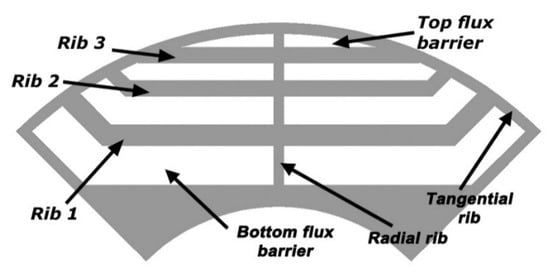
Figure 1.
Geometry of the experimental flux-barrier rotor quarter.
Table 2.
The key geometric dimensions of the version_0 rotor.
The investigation was carried out on four regularly used stator core geometries with cutouts of varying shapes and sizes. These cutouts make it easier to put the stator core in the motor housing and, in the case of a short core, prevent it from moving inside the housing. The technological cutouts also allow for the installation of clamps that secure the stator package. The core with interlocks, which are tiny grooves in the core that are occasionally used to assemble laminations to form the core structure, were also tested. As a result of the activities taken, the impact of interlocks and core cutouts on torque ripple generation was investigated. Figure 2 depicts the geometry of all investigated stator core quarters.
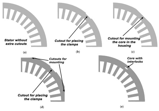
Figure 2.
Geometry of the stator core quarter. (a) Core without any additional cutouts [39], (b) Core with cutouts for clamps [39], (c) Core with cutouts for installation in the housing [39], (d) Core with two types of cutouts, (e) Core with interlocks (visible one interlock).
Each examined stator shape was assigned a name that will be used in subsequent research. The stator core geometries represented in Figure 2 are labeled as: version_s1—Figure 2a, version_s2—Figure 2b, version_s3—Figure 2c, version_s4—Figure 2d, and version_s5—Figure 2e. In the case of version_s5 stator core, three interlocks were used to build the core structure (which is sufficient for a core with such small geometric dimensions), but six or nine interlocks are also a common approach.
2.2. Search for a Rotor Shape That Reduces the Contribution of Stator Slot Harmonics in the Electromagnetic Torque Waveform
According to prior investigations [39], which were expanded in the current campaign, the reluctance motor with the experimental rotor known as version_0 exhibits significant ripple torques, mainly due to stator slot harmonics. The results of computer simulation performed during previous work [39] are presented in Table 3 and Figure 3. It should be noted that all the results and waveforms reported in the previous and current studies were obtained for a steady state. Each numerical simulation started by stopping the rotor and applying the supply voltage. Once the steady state was reached, current measurements, core loss estimations, and torque waveform analysis were conducted over five electrical periods. This approach ensured the accuracy of the results presented.
Table 3.
The dominant torque harmonics calculated from the FEM model for the rotor version_0 (for an average load torque of 0.8 Nm) [39]. The stator slot harmonic has been marked in bold.
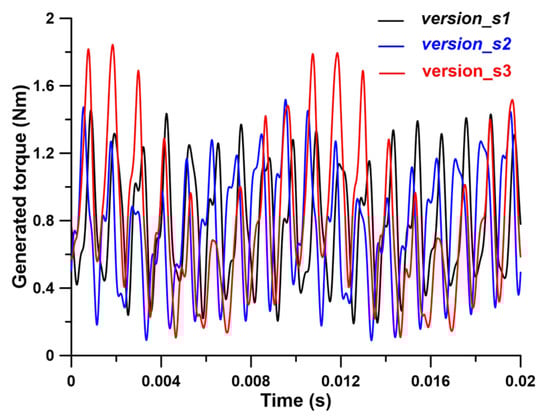
Figure 3.
The calculated waveforms of the generated torque for the version_0 rotor and various stator versions (results for the FEM model with undamaged material).
The results presented above apply to undamaged materials, both in the stator and rotor cores. According to [39], accounting for material damage caused by punching or laser cutting reduces higher harmonic amplitudes by no more than 5%. The amplitudes of higher torque harmonics have a strong influence on torque ripple, which causes noise in the working motor. Analyzing the contents of Table 3 reveals that the torque ripple is dominated by the 36th harmonic (stator slot harmonic). It is evident that lowering the amplitude of this harmonic is necessary to reduce torque ripple. According to the studies detailed in [39], when the motor was loaded with 0.8 Nm torque, torque ripples were 82% for stator version_s1, 103% for stator version_s2, and 139% for stator version_s3, respectively. For this reason, the research campaign’s goal was to significantly decrease the amplitude of the 36th harmonic. It was anticipated that there would be a reduction or no increase in low-order torque harmonics, specifically the 4th and 12th harmonics, generated as a result of shaping the stator core laminates (e.g., version_s2 and versions_s4). According to earlier research, these stator versions generated low-order harmonics with a significant amplitude. The reduction in stator slot harmonic amplitudes and low-order harmonic amplitudes in the torque waveform was the primary measure of success. The proposed new rotor design should allow stator slot harmonic amplitudes to be minimized to no more than 3% of the average motor torque (at rated load, and stator version_s3). For comparison, the motor with the version_0 rotor generated stator slot harmonics with amplitudes up to 55% of average torque at rated load. These findings should be obtained assuming that the geometric dimensions of the changed rotor fragments in the new rotor version will not be smaller than those in the rotor version_0. An additional requirement was that the maximum static torque of the motor with the revised rotor geometry be no more than 10% different from that of the motor with the version_0 rotor (under the same excitation conditions). A search for a new rotor shape that matched the above criteria was done for a motor loaded with 0.8 Nm of torque.
The study found that the share of higher harmonics changes significantly when average torque decreases. The change affects both the amplitudes and the percentage contribution to the average torque. There is no consistent trend, as some harmonics’ share increases while others decreases with decreased average load torque.
During the research campaign, a new rotor geometry was explored to reduce torque ripple by investigating the influence of factors such as the presence and width of radial ribs, the shape of the flux barrier ends near the air gap, the width of tangential rib fragments adjacent to the internal flux barriers, and the width and position of the flux barriers. Table 4 compares the geometric dimensions of the rotor fragments in the old and new versions. Due to the large number of geometric parameters, a manual approach was developed in which one parameter was altered in each computation step while the rest remained unchanged. As a result of this study, a rotor with new geometry, referred to as version_1, was adopted. Figure 4 and Table 4 show a comparison of the rotor shape changes between versions_0 and 1.
Table 4.
Comparison of the geometric dimensions of the version_0 and version_1 rotors.

Figure 4.
Comparison of the initial and new rotor geometries. On the right—version_0, and on the left—version_1.
3. FEM Models and Calculation Results
3.1. Basic Information on FEM Models
As indicated in the previous chapter, a FEM model was used to calculate the higher harmonic amplitudes of the electromagnetic torque waveform. This model was created to handle both magnetostatic calculations with a stationary rotor (in conjunction with the D-Q motor model) and time-stepping calculations with a rotating rotor. Particular emphasis was placed on creating a sufficiently dense mesh because their proper preparation is crucial for the FEM model. Areas with arcs or rounded edges, such as flux barriers, need to be refined. This mesh refinement is evident in Figure 5b, where the rotor has flux barriers with rounded ends (rotor version_1), unlike rotor version_0 in Figure 5a. Special attention should be given to preparing the air gap mesh. In the models used, the air gap is divided into three layers, with one layer highlighted in yellow in Figure 5c being re-meshed after rotor rotation. Care was taken to ensure that the triangle elements were not too narrow to reduce numerical errors and improve the solution’s convergence. The colors of the areas visible in Figure 5c have the following meanings: The red area represents a section of the stator slot, the blue area represents the core, the grey area represents the air gap, and the yellow area represents the part of the air gap that is subject to remeshing. To create a mesh with triangular elements, a specific number of nodes (30 in total) were required along the stator slot pitch and an equal number of nodes on the rotor surface. The air gap consisted of approximately 9000 first-order triangular elements, while the rest of the model comprised around 30,000 first-order elements. The number of nodes along the stator slot pitch was linked to a computational time step of 40 µs. Consequently, after rotating the rotor by an elementary angle and remeshing, the elements in the yellow mesh region formed a shape similar to that shown in Figure 5c. The motor’s FEM model solved the field-circuit problem by calculating the instantaneous current flowing through the stator windings. The currents were determined by connecting the stator windings to an electrical circuit that was provided with a sinusoidal voltage of a specific amplitude and frequency, taking into account the actual position of the rotor. The circuit model also considered the leakage inductance at the ends of the stator windings, which required a 3D FEM model to estimate this value. To achieve this, the author utilized their previous work on the production version of the motor [41]. The stator core’s geometry, size, and winding parameters were kept consistent with the currently tested motor variants, but a different rotor type was used. The previous research enabled the estimation of leakage inductance using the 3D model and comparison with the value derived from the D-Q model. The estimated inductance value was found to be in the hundreds of μH in both the D and Q axes. Further computations enabled the calculation of linked fluxes in both axes. This time, the values reached several hundred mH (for a current close to the rated current). As a result of the investigation, the motor torque was computed using 2D and 3D FEM models and compared to measured data. Under rated conditions, the torques calculated from the 2D and 3D models differed by 3%, while the 3D model’s torque differed by 0.5% from the measured torque. These findings provided the basis for omitting leakage inductance while computing torque in the current calculation campaign using the 2D FEM model, while accounting for its presence in the circuit model. The field-circuit problem was solved using professional software that took into account the motor’s working conditions, such as the specified load torque, the moment of inertia, and the amplitude and frequency of the voltage supplied to the motor. It should be noted that during the simulation, the rotor was free to orient itself relative to the direction of the magnetic field vector generated by the stator winding. Since several stator core shapes (Figure 2) and rotor shapes (Figure 4) were investigated, multiple FEM models were employed, each adapted to the actual stator core and rotor shapes. Figure 5 depicts example meshes for the motor’s rotor versions_0 and 1.
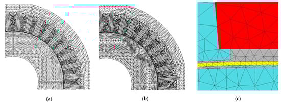
Figure 5.
Fragment of the mesh in the FEM model. (a) model with version_0 rotor, (b) model with version_1 rotor, (c) air gap mesh.
Each FEM model allowed for the presence of material that had been damaged during the creation of the stator and rotor geometry. The cutting procedure changes the properties of the ferromagnetic material used in the motor core manufacturing. Material characteristics are known to change continuously with distance from the cut edge. Magnetic measurements on rectangular strips of different widths (in practice, from 4 mm to 60 mm) can help establish an analytical model that describes this relationship. However, a Finite Element Method (FEM) model cannot directly capture the continuous changes in material properties. Therefore, it is common practice to isolate multiple material zones of small width (e.g., 1 mm) along the cut edge. These zones are assigned material properties that represent the average material properties (e.g., magnetic permeability, specific iron loss) calculated using the analytical model mentioned above. Research shows that the width of the damaged material zone, where significant changes in material properties occur, ranges from 3 to 4 mm and depends on the cutting process used. According to earlier studies on materials, the author determined that incorporating 2–3 areas of damaged material (each with a 1 mm width) around the cut edge into the FEM model is adequate. Of course, more material studies are required to determine the material properties of these zones, specifically the magnetization characteristic B = f(H) and the specific iron loss curve p = f(B). An example of isolated narrow material zones and the material characteristics assigned to them is shown in Figure 6 and Figure 7. Details on how to identify the properties of specific material zones, their size and position, and other information about the FEM models utilized may be found in [39].
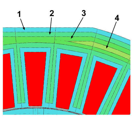
Figure 6.
Fragment of the FEM model with four material zones marked. 1—zone of the most damaged material, 4—zone of undamaged material. Zones 2 and 3 indicate an intermediate level of material destruction.
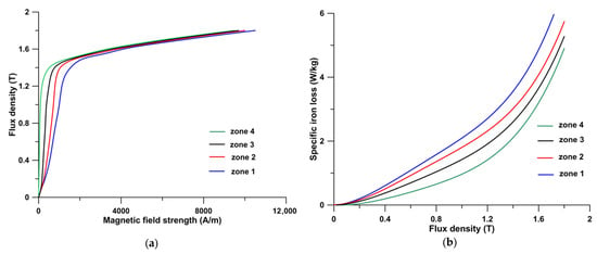
Figure 7.
Determined material curves for individual material zones in the FEM model. (a) B = f(H), (b) p = f(B).
It should be noted that the curves depicted in Figure 7 were determined based on earlier measurements conducted on rectangular specimens with widths ranging from 4 mm to 60 mm using a Single Strip Tester. The B = f(H) and p = f(B) curves are influenced by the cutting technology employed (punching or laser cutting), the parameters of the cutting process (knife clearance, knife wear, cutting speed, laser power, etc.), and the type and thickness of the ferromagnetic laminate. The wear and clearance of the knife have an impact of a few percent on magnetic induction values, especially below 1.4 T and a similar effect on specific iron loss for a given magnetic field strength and induction, respectively. Similar behavior is observed for laser cutting, but this time it is dependent on the cutting speed and laser power. It should be noted that, depending on the cutting technology used, the difference between the B = f(H) and p = f(B) curves is significant. Therefore, it is recommended to attribute the results obtained to specific cutting technology factors. In the analyzed case, the clearance between the knives was 0.1 mm, and knife wear was found to be minimal.
3.2. Simulation Results Obtained from FEM Models
A computational campaign was launched after determining a rotor geometry that matched the conditions outlined in the previous section. The goal was to investigate the impact of both stator lamination geometry and rotor version_1 on the contribution of stator slot harmonics to the torque waveform. Table 5 and Table 6, as well as Figure 8 and Figure 9, show the calculation results for the undamaged material (without considering the cutting process). The comparison was based on the FEM motor model with the stator lamination geometry without any further technological cutouts and the initial version of the rotor geometry (stator version_s1—see Figure 2a, rotor version_0—see Figure 1).
Table 5.
Comparison of dominant torque harmonics calculated from FEM models for the new and old rotor geometry, and the stator version_s1 (calculations for an average load torque of 0.8 Nm). The stator slot harmonic has been marked in bold.
Table 6.
The dominant torque harmonics calculated from FEM models for various variants of stator geometry and version_1 rotor (for an average load torque of 0.8 Nm). The stator slot harmonic has been marked in bold.
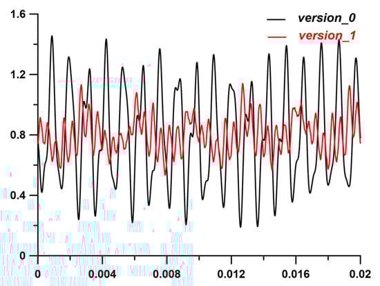
Figure 8.
Comparison of calculated torque waveforms of FEM motor models with version_0 and version_1 rotors. Both waveforms are calculated for version_s1 stator, undamaged materials and an average load torque of 0.8 Nm.
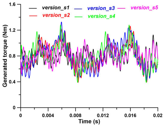
Figure 9.
Comparison of calculated torque waveforms of FEM motor models with version_1 rotor and various stator versions. Results for undamaged materials and an average load torque of 0.8 Nm.
During the research campaign, it was also verified whether the contribution of higher harmonics to the torque waveform varies with load torque. Calculations were performed for the following load torques: 0.8 Nm, 0.7 Nm, 0.6 Nm, 0.5 Nm, and 0.4 Nm. Calculations for lower load torques were not performed due to the reluctance motor’s load range during normal operation. Figure 10, Figure 11 and Figure 12 present examples of the differences in the contributions of significant harmonics (i.e., 4, 36, and 72) obtained for the specified load torque range using the version_1 rotor and the five different configurations of the stator lamination geometry that were tested.
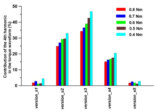
Figure 10.
Comparison of the 4th harmonic contribution to the torque waveform vs. the load torque and stator laminate version.

Figure 11.
Comparison of the 36th harmonic contribution to the torque waveform vs. the load torque and stator laminate version.
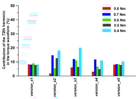
Figure 12.
Comparison of the 72nd harmonic contribution to the torque waveform vs. the load torque and stator laminate version.
It should be noted that for stator laminates version_s3 and version_s4, the stator phase windings were positioned in an asymmetrical arrangement. This is significant information in light of the explanations presented in Section 4.
To enhance the understanding of the practical benefits of the new rotor, standard torque ripple indexes were calculated for a different rotor and stator versions. The standard torque ripple index is determined by subtracting the minimum torque from the maximum torque and then dividing the result by the average torque. The comparison results are presented in Table 7.
Table 7.
Comparison of the calculated standard torque ripple indexes for the new and old rotor geometries and different stator versions.
4. D-Q Models and Calculation Results
The reluctance motor that was tested had its rotor’s type and shape redesigned. It initially featured a salient-pole rotor equipped with a starting cage. It was built as an LSSM (Line Started Synchronous Motor) and configured for direct power from a 50 Hz mains. Changing the rotor type and then redesigning its shape might lead to startup problems. However, no such problems were detected during the current computation investigation. It is widely understood that these types of motors now operate with control systems that offer greater flexibility during starting and operation, while also allowing for direct torque control. This aspect led to the examination and comparison of static torque characteristics against rotor position in relation to the direction of the magnetic field vector generated by the stator windings. This work was completed utilizing both the D-Q and FEM models. The D-Q model defines the relationships between quantities in the natural ABC coordinate system and quantities in the rotating D-Q coordinate system. The instantaneous values of phase currents iA, iB, and iC were determined by inputting the current components iD and iQ. This defined the orientation of the magnetic field vector created by the stator winding relative to the rotor D axis. Equations (1)–(3) describe the specific relationships. Computer simulations done during the previous stage of the investigation (detailed in the previous chapter) allowed for the calculation of phase current waveforms for each investigated stator lamination shape, rotor geometry, and load torque. They also enabled the calculation of the effective current used in Equations (4) and (5). Figure 13 depicts example stator phase current waveforms calculated for a load torque of 0.8 Nm.
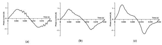
Figure 13.
Calculated stator phase current waveforms for a load torque of 0.8 Nm. (a) stator—version_s1, rotor—version_0, (b) stator—version_s1, rotor—version_1, (c) stator—version_s3, rotor—version_1.
Although, as shown in Figure 13, the third harmonic current occasionally appears, it was thought that the D-Q model description, which implies sinusoidal variation in the phase currents as well as the iD and iQ currents, is sufficient. This strategy is acceptable since, as is known, the third harmonic current does not generate torque. Therefore, applying an inverse transformation from the D-Q system to the natural ABC system, assuming the rotating frame is positioned 90 degrees behind the phase A axis, we may write
where ω is the dq frame rotation speed, ωt is the position of the rotating frame, iD, iQ are the given currents in the D and Q axes, respectively.
iA = iD sin(ωt) + iQ cos(ωt),
iB = iD sin(ωt − 2π/3) + iQ cos(ωt − 2π/3),
iC = iD sin(ωt + 2π/3) + iQ cos(ωt + 2π/3),
The current components iD and iQ were calculated based on the effective current I and the current electric angle α. The electric angle α represents the position of the magnetic field vector with respect to the rotating frame at a specific time. When the electric angle α is 0, the frame’s plane aligns with the direction of the magnetic field vector. The iD and iQ components at any electric angle α of the frame’s position relative to the direction of the magnetic field vector were computed using the following relationships
iD = I cos(α),
iQ = I sin(α),
As it is known, the D-Q model is an analytical model that calculates the average torque generated by the motor. This model uses the flux linkage maps ΨD(iD, iQ) and ΨQ(iD, iQ), which depend on the number of pole pairs, strands, and currents iD, iQ. In the ongoing campaign, the static moment was determined using professional FEM software (OPERA v.19), which did not require knowledge of the flux linkage maps. As a result, the determination of flux linkage maps and analytical calculation of torque were abandoned.
The static torque curve is usually determined by assuming fixed phase current values and rotating the rotor through a predetermined electric angle α. This method, combined with the FEM model, takes into account the variation in reluctance in the air gap region as the rotor rotates through an electric angle α. The consequence of this is the determination of the torque, the value of which is accurate for a given rotor position. This is because it takes into account the mutual position of the stator slot openings and the rotor flux barriers. Changing the reluctance may result in more cogging torques evident on the static torque curve. As a result, using the FEM model, a second strategy was applied that kept the rotor position constant. The stator magnetic field vector was then rotated through an electric angle α by finding the actual values of current components iD and iQ, followed by the current values of phase currents iA, iB, and iC. This method prevented reluctance changes in the air gap area and the formation of extra cogging torques. Figure 14 displays the results of the calculations performed using the second method. The professional software used for magnetostatic calculations requires the current density in the stator windings to be specified. Therefore, in Figure 14 and Figure 15, current density is used instead of current value. For example, a current density of 7.5 × 10⁶ A/mm2 corresponds to a maximum phase current of 1.4 A. This maximum current value is consumed from the mains by a motor with a load torque of 0.8 Nm (motor configuration: stator—version_s3, rotor—version_1).
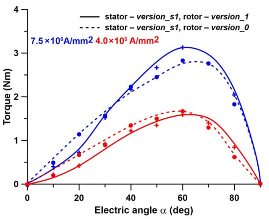
Figure 14.
Comparison of calculated static torque curves (for models with undamaged materials). Points and crosses represent a moving rotor and fixed phase currents; Lines represent an immovable rotor and changing phase currents.

Figure 15.
Comparison of calculated static torque curves for various stator versions and rotor version_1. The results apply to FEM models with undamaged materials.
The simulations performed showed that the arrangement of the phase winding coils in the slots of the stator core is crucial when the stator core has technological cutouts (version_s3 and version_s4). Consequently, two different arrangements of the phase coils were evaluated. In the first arrangement, the phase winding coils were positioned asymmetrically with respect to the cutouts in the stator laminations (see Figure 16a), while in the second arrangement, they were positioned symmetrically (see Figure 16b). Three colors were used to identify the slots for the individual phase windings.
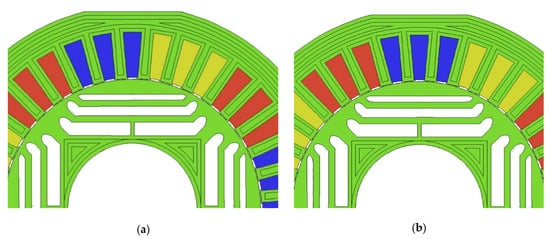
Figure 16.
The arrangement of the phase winding coils in relation to the technological cutouts of the stator laminate. (a) asymmetrical arrangement, (b) symmetrical arrangement.
5. Impact of Damaged Material on Torque Ripple and Static Torque Curves
Earlier discussions about how damaged core material affects the performance of a reluctance motor with a rotor in version_0 were covered in [39]. The size and shape of material zones in which the material properties changed as a result of the cutting process were discussed in detail. It was demonstrated that in the SynRM motor under study, taking damaged material into account resulted in: a several percent reduction in the amplitudes of stator slot harmonics in the torque waveform (torque ripple); an increase in the RMS value of the current consumed from the grid; an increase in the stator core losses, and a decrease in efficiency. This research expands and supplements the prior findings.
Simulation Results Obtained from FEM and D-Q Models
The calculated higher harmonics in the torque waveform were examined for a motor with a version_1 rotor, where the stator and rotor laminations were punched. The obtained results enabled us to identify how the laminate cutting procedure affected the share of particular higher harmonics in the torque waveform. For this purpose, the results from the FEM model, which included only undamaged material, were used as a reference base. In the model with cut laminates, the share of low-order harmonics in the torque waveform decreased somewhat while the share of stator slot harmonics increased. The degree of increase was determined by both the stator core version and the motor load. Figure 17, Figure 18 and Figure 19 show the results of a comparison of the shares of selected harmonics, i.e., the 4th, 36th, and 72nd, determined for load torque in the range of 0.4 Nm to 0.8 Nm.
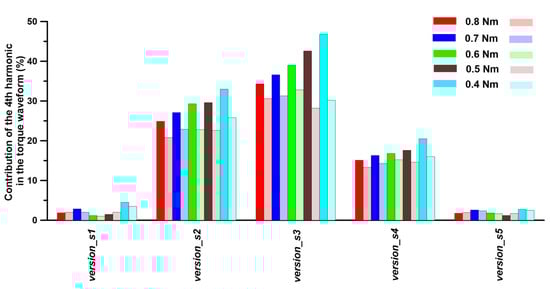
Figure 17.
Comparison of the 4th harmonic contribution to the torque waveform vs. load torque and stator laminate version. The left rectangles in the legend represent results for undamaged material, while the right rectangles in the legend represent results for punched material.
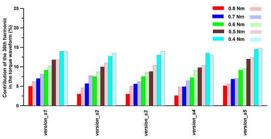
Figure 18.
Comparison of the 36th harmonic contribution to the torque waveform vs. load torque and stator laminate version. The left rectangles in the legend represent results for undamaged material, while the right rectangles in the legend represent results for punched material.
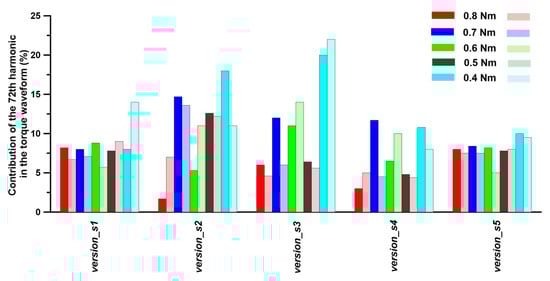
Figure 19.
Comparison of the 72nd harmonic contribution to the torque waveform vs. load torque and stator laminate version. The left rectangles in the legend represent results for undamaged material, while the right rectangles in the legend represent results for punched material.
The previous chapter demonstrated the importance of the location of the phase winding coils in the version_s3 stator (as well as version_s4). The arrangement of the phase winding coils in relation to the technological cuts in the stator lamination is essential. As previously stated, this has a visible impact on the calculated static torque characteristics. A similar effect can be observed by examining the harmonic content of the torque waveform. Table 8 summarizes the observations. When compared to the asymmetrical coil arrangement, the contribution of the 36th harmonic was reduced by 10%, while the contribution of low-order harmonics was reduced by 20–30%. Similar relationships were found for both the stator in version_s4 and the various motor load torques. The stator geometry versions_s2 and _s5 did not show such a relationship, i.e., no significant change in harmonic content was observed as a result of the phase winding coil arrangement.
Table 8.
Comparison of dominant torque harmonics calculated in FEM models for various stator coils arrangement (calculations for an average load torque of 0.8 Nm). Stator version_s3. The stator slot harmonic has been marked in bold.
In the next step of the campaign, the static torque curves of the reluctance motor were compared, taking into account the position of the phase winding coils relative to the technological cutouts (stator versions_s3 and _s4). In this context, the impact of the laminate forming process on static torque curves was examined. Figure 20 and Table 9 present the findings of the comparison.
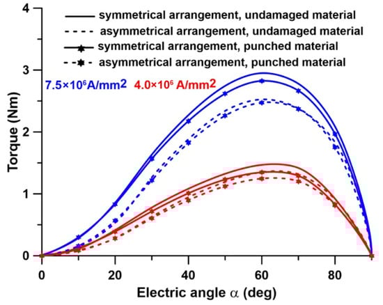
Figure 20.
Comparison of calculated static torque curves for stator version_s3.
Table 9.
Comparison of calculated static torques for specified electric angle, and various coil arrangement. Stator version_s3, fixed phase current density equals to 7.5 × 10⁶ A/mm2.
Analyzing Table 9, we can observe that the presence of damaged material affects the maximum torque by 3–4% for the given phase current density and coil arrangement. It was found that the coil arrangement determines the greatest difference in maximum torque. A motor with a symmetrical coil configuration generates up to 17% more static torque than a motor with an asymmetrical coil arrangement, assuming the same phase current density and rotor position.
Table 10, Table 11 and Table 12 present a summary of calculation results by comparing RMS values for phase currents, power loss components, total losses (including mechanical losses of 2 W), and motor efficiency.
Table 10.
Comparison of the RMS value of the consumed current and Joule losses in the windings for a motor with a version_1 rotor and a load torque of 0.8 Nm.
Table 11.
Comparison of the iron losses and total losses for a motor with a version_1 rotor, a load torque of 0.8 Nm, and frequency of 50 Hz.
Table 12.
Comparison of motor efficiency for a motor with a version_1 rotor and a load torque of 0.8 Nm, and frequency of 50 Hz.
6. Discussion and Conclusions
Synchronous reluctance motors are frequently used due to their low manufacturing costs and simple design, with the rotor playing a significant role. Optimizing the rotor form entails choosing not only the shape and dimensions of individual barriers but also their number. It is recognized for allowing, among other things, a reduction in torque ripples. Another benefit of improving the rotor shape is a large improvement in motor torque density, which is obtained by adding permanent magnets. The literature on optimizing reluctance motors with a flux barrier rotor is extensive and is covered in the Introduction. However, descriptions of optimized designs for motors with an outer stator core diameter less than 120 mm are relatively limited. It should be noted that these are motors with significant technological influences on performance, needing more exploration. The research reported here focuses on minimizing the contribution of stator slot harmonics to torque waveforms, thereby addressing a knowledge gap in this field. As the calculation results indicate, these harmonics have a significant impact on the magnitude of torque ripples. Hence, limiting their contribution will have a direct impact on the amplitude of the torque ripples. The most common action algorithms available in the literature are based on the optimization of the barrier shape, which is represented by various types of curves. In this study, the approach was improved to account for flow barriers’ “range/length”. The research findings presented here are applicable to motors with small geometric dimensions, i.e., motors with stator teeth and rotor barriers that are just a few mm wide, while the stator and rotor yokes are approximately 10 mm wide. As indicated in the article, it is critical to account for any damage to magnetic core parts induced by the laminate formation process. Furthermore, technological cutouts in stator laminates were found to have an impact on motor performance. Additionally, it was revealed that the amplitudes of stator slot harmonics in the torque waveform, as well as the static torque curve, are very sensitive to the presence of cutouts. The mentioned cutouts are required to assemble the stator core or mount a short core package (on the order of a few cm) in the housing, as is the case with the 120 W motor under examination. In the literature, we may locate an example of a study results description that addresses the issues highlighted in a simple manner [42]. The authors of the mentioned research did not determine the material properties of specific parts of the material at the cut edge, but rather used three equivalent material properties measured for toroidal cores with various widths.
The analysis of the influence of technological cutouts reported in this article significantly adds to the current literature. For comparison, let us take the study [43] in which technological cutouts were present (as shown in the images) but not included in the FEM model. This strategy is justified by the size of the rotor’s outer diameter, which in this case was 200 mm. The article’s results indicate that, at such dimensions, the use of technological cutouts had no effect on the obtained results. Another problem is the presence of material fragments with properties changed as a result of the laminate forming process. The computer simulations clearly illustrate that accounting for the existence of a material with partially changed properties resulted in a decrease in harmonic amplitudes in the torque waveform. For example, the amplitudes of low-order (e.g., 4th) and high-order (e.g., 72nd) harmonics decreased by several percent, while the amplitude of stator slot harmonics (36th) increased by a few dozen percent. The reported results are extremely consistent with the findings of other studies, which discovered a several percent decrease in torque ripple as a result of accounting for partially damaged material [32]. As previously stated, the stator core geometry has a significant impact on the amplitudes of low-order harmonics. The stator core laminates in versions_s3 and _s4 “generated” the largest amplitudes of the fourth torque harmonic. As a result, it was possible to conclude that these are induced harmonics “generated” by the use of stator laminates of a particular shape. At the same time, the aforementioned stator core versions “generated” the lowest amplitudes of stator slot harmonics when compared to the other versions. In case of version_s5, the interlocks should be positioned above the stator teeth, halfway up the stator yoke. Even with nine interlocks instead of three, their influence on torque pulsation, torque harmonic amplitudes, iron losses, and current consumption is minimal approximately 1–2%.
During the experiments, it became clear that the amplitudes of higher harmonics (in the torque waveform) varied with the change in the average load torque. As the load torque decreased, the amplitude and percentage share of higher harmonics increased (Figure 17, Figure 18 and Figure 19). This increase was observed across all stator core laminate shapes. The experiments demonstrated that including partially damaged material in the model reduced the value of the motor’s static torque by several percent for a given current density and electric angle (Figure 20 and Table 8). The reported several percent reduction in the maximum value of generated torque is consistent with the findings of other researchers [44]. It was observed that two potential stator phase winding configurations, located in versions_s3 and _s4 of the stator core, generated substantially different static torque. These are new insights that have not been reported in the existing literature. It should be noted that the research conducted resulted in a significant decrease in the amplitude of the 36th harmonic, which is a major contributor to torque ripple. For a motor loaded with a torque of 0.8 Nm, it was more than half of the average torque in the original rotor version (version_0). The revised rotor version (version_1) reduced its contribution to 3–5%, depending on the shape of the stator core laminations, while taking into consideration partially degraded materials.
This paper addresses knowledge gaps in rotor design and flux barrier shape selection for small motors, with a focus on computer simulation findings. It clearly demonstrates that the design strategy must take into account the technological processes involved in core shaping. At the same time, it significantly extends on the findings of [39] and a few other published works in this field.
Based on the simulation studies conducted, I recommend the following design guidelines for developing compact SynRM motors:
- -
- When shaping laminates with a laser or punching, it is important to select rotor geometry in a way that ensures the rotor ribs are wider than 1 mm. This recommendation is more stringent than the one given in [45].
- -
- It is recommended to round the ends of the flux barriers, and choose 3–5 flux barriers based on the available options.
- -
- If the width of the rotor core fragments is less than 8–10 mm, the impact of shaping the laminate geometry on material properties should be taken into consideration. In such a case, additional material tests should be conducted, considering the cutting technology and current cutting tool parameters, in order to obtain new material curves such as B = f(H) and p = f(B).
- -
- The presence of cutouts in the stator core, used for securing the core to the housing and for core clamps, leads to low-order torque harmonics. The amplitudes of these harmonics vary depending on the size of the cutouts. Utilizing both types of cutouts helps reduce the amplitude of low-order harmonics compared to using only mounting cutouts or clamp cutouts.
- -
- As the average torque decreases, the amplitudes of individual torque harmonics increase. A similar trend is observed with the standard torque ripple index, which can increase by up to 80% when the average torque decreases from the rated torque to half of the rated torque.
- -
- It is recommended to arrange the phase winding symmetrically in relation to the cutouts used to mount the core in the housing.
The third and final step of the ongoing study cycle will include the production of prototype rotors with the shapes version_0 and version_1, as well as a comparison of measurement results and computer simulations.
Funding
This research received no external funding.
Institutional Review Board Statement
Not applicable.
Informed Consent Statement
Not applicable.
Data Availability Statement
The data underlying this article will be shared on reasonable request to the corresponding author.
Conflicts of Interest
The author declares no conflicts of interest.
Abbreviations
| SynRM | Synchronous Reluctance Motor |
| FEM | Finite Element Method |
| D-Q model | Direct-Quadrate model |
| RMS value | Root Mean Square value |
| ABC system | a system with vectors A, B, C shifted by 120 degrees |
References
- Gmyrek, Z.; Smółka, K. Efficiency analysis of fractional kilowatt reluctance motors with various frame sizes, taking into account the impact of the punching Process. Energies 2020, 13, 357. [Google Scholar] [CrossRef]
- Mohammadi, A.A.; Zhang, S.; Pop, A.-C.; Gyselinck, J. Effect of electrical steel punching on the performance of fractional-kW electrical machines. IEEE Trans. Energy Convers. 2022, 37, 1854–1863. [Google Scholar] [CrossRef]
- Oyamada, M.; Wakasugi, S.; Moriyama, Y.; Koga, F. Standalone testing method of synchronous reluctance motor for determining operating characteristics. In Proceedings of the 27th International Conference on Electrical Machines and Systems (ICEMS), Fukuoka, Japan, 26–29 November 2024; pp. 468–475. [Google Scholar] [CrossRef]
- Di Nardo, M.; Gallicchio, G.; Korman, O.; Riccio, J.; Vannini, A.; Degano, M.; Gerada, C.; Hague, R.; Gargalis, L. Experimental assessment of a synchronous reluctance machine featuring an additive manufactured rotor. In Proceedings of the IEEE Workshop on Electrical Machines Design, Control and Diagnosis (WEMDCD), Valletta, Malta, 9–10 April 2025. [Google Scholar] [CrossRef]
- Lefik, M.; Gmyrek, Z. Numerical modelling of a flux-barrier synchrel motor including punching effect. COMPEL Int. J. Comput. Math. Electr. Electron. Eng. 2016, 35, 2087–2094. [Google Scholar] [CrossRef]
- Credo, A.; Petrov, I.; Pyrhönen, J.; Villani, M. impact of manufacturing stresses on multiple-rib synchronous reluctance motor performance. IEEE Trans. Ind. Appl. 2023, 59, 1253–1262. [Google Scholar] [CrossRef]
- Bramerdorfer, G. Effect of the manufacturing impact on the optimal electric machine design and performance. IEEE Trans. Energy Convers. 2020, 35, 1935–1943. [Google Scholar] [CrossRef]
- Sun, Y.; Lin, Y.; Wang, Y.; Mohammadi, A.A.; Gyselinck, J.; Shen, J.-X. The influence of the uncertainty of flux-bridge width and BH-curve on synchronous reluctance machines performance. In Proceedings of the 23rd International Conference on Electrical Machines and Systems (ICEMS), Hamamatsu, Japan, 24–27 November 2020. [Google Scholar] [CrossRef]
- Stewart, A.; Simpson, N.; Mellor, P. Adaptive laser machining and synchronous reluctance machine design. In Proceedings of the IEEE Energy Conversion Congress and Exposition (ECCE), Phoenix, AZ, USA, 20–24 October 2024. [Google Scholar] [CrossRef]
- Oka, M.; Kawano, M.; Shimada, K.; Kai, T.; Enokizono, M. Evaluation of the magnetic properties of the rotating machines for the building factor clarification. Electr. Rev. 2011, 87, 43–46. [Google Scholar]
- Pop, A.-C.; Pinto, D.E.; Tuchsen, J.; Koch, M. Robustness to large-scale mass production manufacturing tolerances by means of sensitivity and statistical analysis for IPMSMs. IEEE Trans. Energy Convers. 2020, 35, 2201–2209. [Google Scholar] [CrossRef]
- Bojoi, R.; Cavagnino, A.; Gmyrek, Z.; Lefik, M. Experimental assessment of the annealing effects on magnetic core of fractional power synchronous reluctance motors. In Proceedings of the 2016 XXII International Conference on Electrical Machines (ICEM), Lausanne, Switzerland, 4–7 September 2016. [Google Scholar] [CrossRef]
- Murataliyev, M.; Degano, M.; Di Nardo, M.; Bianchi, N.; Gerada, C. Synchronous reluctance machines: A comprehensive review and technology comparison. Proc. IEEE 2022, 110, 382–399. [Google Scholar] [CrossRef]
- Chiang, C.-C.; Knight, A.M.; Hsieh, M.-F.; Tsai, M.-G.; Liu, B.H.; Chen, I.-G.; Gaing, Z.-L.; Tsai, M.-C. Effects of annealing on magnetic properties of electrical steel and performances of SRM after punching. IEEE Trans. Magn. 2014, 50, 8203904. [Google Scholar] [CrossRef]
- Chen, Y.; Wang, Y.; Li, X.; Qu, R. Design of an IE5 5.5kW synchronous reluctance machine with low torque ripple. In Proceedings of the 2023 26th International Conference on Electrical Machines and Systems (ICEMS), Zhuhai, China, 5–8 November 2023. [Google Scholar] [CrossRef]
- Liu, C.; Wang, K.; Wang, S.; Wang, Y.; Zhu, J. Torque ripple reduction of synchronous reluctance machine by using asymmetrical barriers and hybrid magnetic core. CES Trans. Electr. Mach. Syst. 2021, 5, 13–20. [Google Scholar] [CrossRef]
- Credo, A.; Fabri, G.; Di Leonardo, L.; Villani, M. Synchronous reluctance motor with fluid shaped barriers: Preliminary and optimized design procedures. In Proceedings of the IECON 2021–47th Annual Conference of the IEEE Industrial Electronics Society, Toronto, ON, Canada, 13–16 October 2021. [Google Scholar] [CrossRef]
- Parveen, H.; Sharma, U.; Singh, B. Impacts of barrier shape on torque ripple and saliency in synchronous reluctance motor for solar water pumping. In Proceedings of the 2020 IEEE International Conference on Power Electronics, Smart Grid and Renewable Energy (PESGRE), Cochin, India, 2–4 January 2020. [Google Scholar] [CrossRef]
- Fiorito, A.; Murataliyev, M.; Carbone, L.; Di Nardo, M.; Degano, M.; Nuzzo, S. Rotor optimization of a synchronous reluctance machine for railway applications. In Proceedings of the 2024 International Conference on Electrical Machines (ICEM), Torino, Italy, 1–4 September 2024. [Google Scholar] [CrossRef]
- Xu, Y.; Xu, Z.; Cao, H.; Liu, W. Torque ripple suppression of synchronous reluctance motors for electric vehicles based on rotor improvement design. IEEE Trans. Transp. Electrif. 2023, 9, 4328–4338. [Google Scholar] [CrossRef]
- Da Silveira, G.B.; Wiltuschnig, I.P.; Homrich, R.P.; Filho, Á.F.F.; Salton, A.T.; dos Santos, L.G.T.; Soares, C.d.A.; Eckert, P.R. A comparative performance study of high-speed SynRM and PMa-SynRM rare-earth and rare-earth-less permanent magnets for automotive traction. In Proceedings of the 2024 IEEE International Magnetic Conference, Rio de Janeiro, Brazil, 5–10 May 2024. [Google Scholar] [CrossRef]
- Ayman, B.; El Samhay, A.A.; Rashad, E.M.; Shindy, I.M. Comparative study of different flux barrier shapes for performance evaluation of synchronous reluctance motors. In Proceedings of the 2024 25th International Middle East Power System Conference (MEPCON), Cairo, Egypt, 17–19 December 2024. [Google Scholar] [CrossRef]
- Asama, J.; Kawamura, M. Efficiency Comparison of synchronous reluctance machines with different rotor designs. In Proceedings of the 2023 IEEE International Electric Machines & Drives Conference (IEMDC), San Francisco, CA, USA, 15–18 May 2023. [Google Scholar] [CrossRef]
- Bao, M.; Wang, Y.; Mao, C.; Li, J.; Feng, S.; He, T.; Chen, Y.; Qu, R. Novel design method of flux-barrier end shape of synchronous reluctance motor based on B-spline curves. In Proceedings of the 2023 IEEE 6th Student Conference on Electric Machines and Systems (SCEMS), Zhou, China, 7–9 December 2023. [Google Scholar] [CrossRef]
- Kim, H.; Park, Y.; Oh, S.-T.; Jang, H.; Won, S.-H.; Chun, Y.-D.; Lee, J. A Study on the rotor design of line start synchronous reluctance motor for IE4 efficiency and improving power factor. Energies 2020, 13, 5774. [Google Scholar] [CrossRef]
- Mirzaei, A.; Rad, N.A.; Torkaman, H.; Zarghani, A. comparison study and performance enhancement of induction motor using optimized SynRM for household applications. In Proceedings of the 2023 3rd International Conference on Electrical Machines and Drives (ICEMD), Tehran, Iran, 20–21 December 2023. [Google Scholar] [CrossRef]
- Sai, P.K.R.; Deepak, M.; Bharatiraja, C. Design and modifications of rotor flux barrier in synchronous reluctance motor for E-bike. In Proceedings of the 2023 International Conference on Electrical, Electronics, Communication and Computers (ELEXCOM), Roorkee, India, 26–27 August 2023. [Google Scholar] [CrossRef]
- Zheng, Y.; Wang, Y.; Li, D.; Li, X.; Zhang, C.; Qu, R.; Bianchi, N. A torque ripple reduction method for the synchronous reluctance machines with mirror asymmetric rotor laminations. IEEE Trans. Ind. Electron. 2025, 72, 10497–10507. [Google Scholar] [CrossRef]
- Zhang, J.; Xing, F.; Kang, L.; Qin, C. Design and multi-objective optimization for improving torque performance of a permanent magnet-assisted synchronous reluctance motor. Appl. Sci. 2024, 14, 5253. [Google Scholar] [CrossRef]
- Wan, W.-J.; Li, Z.-C.; Lu, J.-P.; Wang, Y.; Shi, D.; Shen, J.-X. Fast design methodology for synchronous reluctance machine rotor with circular flux barriers. IEEE Trans. Ind. Appl. 2025, 61, 6951–6961. [Google Scholar] [CrossRef]
- Zhang, S.; Liu, C.; Wang, Y.; Niu, F.; Lei, G.; Zhu, J. Shape design optimization and comparative analysis of a novel synchronous reluctance machine with grain-oriented silicon steel. IEEE Trans. Magn. 2024, 60, 8101705. [Google Scholar] [CrossRef]
- Hidaka, Y.; Igarashi, H. Topology Optimization of synchronous reluctance motors considering localized magnetic degradation caused by punching. IEEE Trans. Magn. 2017, 53, 7000804. [Google Scholar] [CrossRef]
- Gilch, I.; Hartmann, C.; Grünhag, B.; Volk, W.; Schauerte, B.; Leuning, N.; Hameyer, K. Residual stresses and magnetic material properties of embossed and cut magnetic flux barriers in non-oriented electrical steel under tensile load. In Proceedings of the 2023 13th International Electric Drives Production Conference (EDPC), Regensburg, Germany, 29–30 November 2023. [Google Scholar] [CrossRef]
- Credo, A.; Pescetto, P. A Systematic method for the calibration of FEA model of synchronous reluctance machines considering manufacturing effects. IEEE Open J. Ind. Appl. 2025, 6, 539–550. [Google Scholar] [CrossRef]
- Seo, U.-J.; Kim, D.-J.; Chun, Y.-D.; Han, P.-W. Mechanical cutting effect of electrical steel on the performance of induction motors. Energies 2020, 13, 6314. [Google Scholar] [CrossRef]
- Vanthuyne, K.; Gulec, M.; Sergeant, P. High-frequency motor modelling: Parameter variation due to manufacturing. In Proceedings of the 2022 International Conference on Electrical Machines (ICEM), Valencia, Spain, 5–8 September 2022. [Google Scholar] [CrossRef]
- Ion, C.P.; Peter, I. Manufacturing of induction motors with super premium efficiency. In Proceedings of the 2022 International Conference and Exposition on Electrical and Power Engineering (EPE), Iasi, Romania, 20–22 October 2022. [Google Scholar] [CrossRef]
- Zhao, H.; Chu, C.; Eldeeb, H.H.; Zhan, Y.; Xu, G.; Mohammed, O.A. Optimal design of high-speed solid rotor cage induction motors considering ferromagnetic materials behavior and manufacturing Process. IEEE Trans. Ind. Appl. 2020, 56, 4345–4355. [Google Scholar] [CrossRef]
- Gmyrek, Z. The Impact of the core laminate shaping process on the parameters and characteristics of the synchronous reluctance motor with flux barriers in the rotor. Energies 2025, 18, 1222. [Google Scholar] [CrossRef]
- Linh, D.H.; Dinh, B.M.; Khue, T.K.; Quoc, V.D. Evaluation of flux-barriers for synchronous reluctance motors. In Proceedings of the 2023 12th International Conference on Control, Automation and Information Sciences (ICCAIS), Hanoi, Vietnam, 27–29 November 2023. [Google Scholar] [CrossRef]
- Gamba, M.; Pellegrino, G.; Cavagnino, A.; Gmyrek, Z.; Lefik, M. Rotor end effects on FEM-based flux mapping of synchronous reluctance motors. In Proceedings of the 2017 IEEE International Electric Machines and Drives Conference (IEMDC), Miami, FL, USA, 21–24 May 2017. [Google Scholar] [CrossRef]
- Credo, A.; Kurvinen, E.; Petrov, I.; Scherman, E.; Sopanen, J.; Pyrhonen, J. Materials applicable to an axially-laminated synchronous reluctance machine considering mechanical and electromagnetic aspects. IEEE Trans. Ind. Appl. 2024, 60, 153–163. [Google Scholar] [CrossRef]
- Peng, C.; Wang, D.; Feng, Z.; Wang, B. A new segmented rotor to mitigate torque ripple and electromagnetic vibration of interior permanent magnet machine. IEEE Trans. Ind. Electr. 2022, 69, 1367–1377. [Google Scholar] [CrossRef]
- Credo, A.; Fabri, G.; Villani, M.; Popescu, M. Adopting the topology optimization in the design of high-speed synchronous reluctance motors for electric vehicles. IEEE Trans. Ind. Appl. 2020, 56, 5429–5438. [Google Scholar] [CrossRef]
- Niazi, P.; Toliyat, H.A.; Cheong, D.-H.; Kim, J.-C. A low-cost and efficient permanent-magnet-assisted synchronous reluctance motor drive. IEEE Trans. Ind. Appl. 2007, 43, 542–550. [Google Scholar] [CrossRef]
Disclaimer/Publisher’s Note: The statements, opinions and data contained in all publications are solely those of the individual author(s) and contributor(s) and not of MDPI and/or the editor(s). MDPI and/or the editor(s) disclaim responsibility for any injury to people or property resulting from any ideas, methods, instructions or products referred to in the content. |
© 2026 by the author. Licensee MDPI, Basel, Switzerland. This article is an open access article distributed under the terms and conditions of the Creative Commons Attribution (CC BY) license.