Abstract
Contemporary business process modeling lacks a systematic framework for converting unstructured requirements into structured models. Traditional manual approaches fail to support integrated lifecycle management from requirements elicitation to iterative model refinement. The gap severely limits the efficiency and accuracy of the alignment between requirements and business process modeling and often leads to costly rework and implementation errors in complex software projects. Therefore, this paper aims to establish a coherent modeling framework from requirements extraction to business process model verification. The framework maintains the traceability and consistency of the unstructured requirements through three tasks: (1) automatic generation of a structured requirements model from textual input to a set of designed prompts of hyperparameter-optimized large language models (LLMs); (2) establishment of a modeling routine to handle the iterative requirements via two sets of formalized mapping rules, a merging algorithm, and a toolkit; (3) detection of the obtained CBPMN model by a static flow error verification algorithm and reachability verification using CPN tools 4.0. A total of 15 sets of comparative experiments with three state-of-the-art automated modeling approaches demonstrate the superiority of our method in generating higher-quality requirements models, while an additional case study with two-step verification proves its validity.
1. Introduction
A business process, defined as a series of interrelated activities within or between organizations, is fundamental to organizational value creation: precise business process models enable data-driven optimization and iterative improvement to meet evolving customer demands [1]. However, a persistent methodological challenge lies in the significant semantic gap between informal stakeholder needs and formal verifiable process specifications, which often leads to information loss and deviation during model construction [2]. This gap is rooted in the traditional labor-intensive paradigm of requirements engineering, which struggles with the ambiguity of natural language and the dynamic nature of business requirements [3].
The confirmation of requirements is not as simple as generating a conceptual model from a prepared document; it involves a complete framework containing requirements collection and modeling, an execution carrier for the requirements structure, verification of the execution model, and a systematic approach that integrates all of these components. However, an efficient professional modeling method comes from long-term learning, logical sorting, and accumulation of knowledge in a certain field, which hinders the automation of the general construction of complex requirements in business process modeling [4,5]. Meanwhile, changing markets impose consequent requirements for incremental improvements to the business process model [6]. Therefore, researchers are looking for solutions to construct an iterative process model with complexity and relative stability to address the dynamic changes in requirements.
Studies to bridge this gap have evolved along two primary directions. On the one hand, agile and iterative methodologies focus on enhancing the adaptability of business process models to changing requirements [7,8,9,10,11]. While effective in keeping up with requirements evolution, these approaches typically presuppose the existence of an initial correct model, offering limited guidance on its systematic derivation from ambiguous initial requirements. On the other hand, general requirements engineering (RE) advances provide powerful domain-agnostic patterns for requirements handling and formal specifications, but the automated synthesis of executable business process models imposes unique constraints. These include the need to explicitly capture multidimensional perspectives, hierarchical decomposition, complex execution semantics, and the integration of multiple stakeholder views into a single, logically coherent, and executable workflow model [12]. Existing LLM-for-RE approaches, while proficient in generating isolated artefacts like UML class diagrams or code snippets, often lack the domain-specific formalization mechanism to guarantee the structural integrity, behavioral consistency, and executability of synthesized business process models. Conversely, dedicated formalized process modeling approaches, such as BPMN or Petri nets, offer the necessary semantic precision but are disconnected from integrating automation and requirements-driven synthesis.
In response to this trend, the Problem Frames (PFs) method proposed by Mickle Jackson focuses on the interaction between a system and its environment, modeling software based on realistic requirements [13]. The PFs method divides the system into three parts: requirements, the problem domain (PD), and the machine domain. Requirements and the PD are linked by requirement phenomena, while the PD and the machine domain are connected by shared phenomena, as shown in Figure 1.
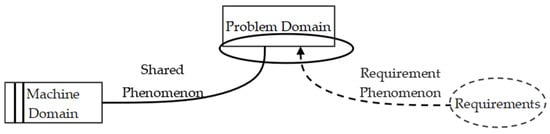
Figure 1.
Problem diagram in the problem frames method.
Requirements are derived from reality and depicted by context diagrams. The PD and machine domain, collectively called “the domain,” are split into internal behavior and external phenomena. Internal behavior refers to the domain’s structure and actions, whereas external phenomena represent the direct interface that selectively transmits information. Shared phenomena occur at the interface between the problem and machine domains, while requirement phenomena link the problem domain with requirements [14].
However, the weakness of PFs is that both the analysis process and the decomposition process of the problem need to be completed manually, which calls for expert experience and the accumulation of knowledge in specific fields. Meanwhile, large language models trained with large amounts of data and corpuses can generally understand human language to a certain extent and output answers depending on the quality of prompts. Therefore, in order to reduce the burden of both the providers and analysts in the process of requirements acquisition, this paper combines PFs with prompt engineering, introducing multiple agents with their own roles to replace the work of requirements providers and analysts. Then, the obtained requirements models are transformed into a set of business process models through transformation rules with matrix computations. The business process model is verified through three layers of verification and simulated by the corresponding colored Petri net (CPN).
Therefore, a pivotal challenge has evolved: the key issue is no longer the automation of requirements elicitation but rather the absence of a formal theoretical bridge that must connect the acquired requirements with executable process models. To construct this bridge, an effective integrated framework must encompass three key capabilities: (1) providing a well-defined requirements model to serve as a consistent target structure for semi-automated parsing tools; (2) establishing a set of formal mapping and transformation rules to ensure semantic fidelity throughout the chain from the requirements model to business process models and further to executable models; and (3) incorporating model integration and verification algorithms to maintain correctness in complex multi-source requirements scenarios.
To address the three challenges above, this study proposes an integrated framework centered on a formal requirement analysis model, combining prompt engineering with formal methods. The specific research objectives are as follows:
- (1)
- To design a structured problem frames-based model (PFM) and automate the generation of its instances from natural language text using optimized LLM prompt strategies.
- (2)
- To verify the feasibility and semantic consistency of PFM by establishing formal mapping rules to a requirement business process model (RBPMN) and an executable colored Petri net (CPN) model.
- (3)
- To ensure the logical correctness of the integrated models by developing algorithms to merge multiple RBPMN models and to detect flow errors in the resulting collaboration BPMN (CBPMN) model.
The remainder of this paper is structured as follows. Section 2 reviews the related work in requirements acquisition and business process modeling. Section 3 introduces the problem frames model (PFM) and formally defines the requirement business process modeling notation (RBPMN), collaboration business process modeling notation (CBPMN), and colored Petri net (CPN) models, collectively forming the PRBC modeling approach. Section 4 proposes an iterative business process modeling methodology, detailing a three-stage process of requirement collection and modeling, mapping requirements to business process models, and model verification and iteration. Section 5 evaluates the quality of prompts for requirements modeling and illustrates the end-to-end modeling process—from natural language requirements to an executable business process model—using a case study of a car-hailing system. Finally, Section 6 concludes the paper and outlines directions for future research.
2. Related Work
To support the business process modeling of iterative requirements, there are three aspects that are worth exploring: requirement elicitation, requirement modeling, and business process modeling and simulation [15].
Requirements elicitation is the process of abstracting and arranging requirement elements from the natural language requirement descriptions using various tools, while LLMs and natural language processing (NLP) have a strong relationship with the automation of requirement elicitation. As a bridge between requirements engineering and process management, business process modeling should conquer the high-fidelity transformation challenge from requirements to business process models, while the advent of LLMs introduces a possible solution for efficient process modeling.
Traditional requirements modeling typically involves manual requirements analysis, where requirements are gathered through questionnaires, interviews, comment analysis, and other methods. After multiple rounds of discussions among user representatives, software project leaders, review experts, and domain experts, requirement descriptions are finalized into formalized models [16,17]. In terms of requirements elicitation, most frameworks incorporate advanced techniques such as machine learning, prompt engineering, as well as NLP, transforming complex requirements into formalized models. For instance, Ruan et al. presented an automated framework that incorporates zero-shot learning based on GPT 3.5 by designing an appropriate prompt to extract a requirement model from requirement texts by employing composition rules [18]. Similarly, Liu et al. created a domain-specific modeling language, constrained natural language input via grammar rules, and established an automatic transformation mechanism to map textual requirements to a state machine model [19]. Additionally, Yilmaz Uygun et al. proposed a Local GPT Q&A retrieval solution aimed at simplifying the requirements analysis process [20].
However, the existing methods face significant limitations. The reliance on rigid syntactic rules, as demonstrated in the work of Liu et al., restricts flexibility in handling vague or evolving requirements. Additionally, document-based modeling approaches often suffer from cross-language semantic inconsistencies, a problem exacerbated by temporal and regional variations that undermine the accuracy of the requirements.
After requirement elicitation, a formalized requirement model is necessary to provide sufficient conditions for business process simulation and verification, thereby improving the quality and efficiency of software performance testing [21]. Focusing on the application development driven by machine learning, Yang et al. [22] developed a metamodel framework based on state machine extensions to enable hierarchical expression and constraint verification of complex system requirements by enhancing UML modeling capabilities. In the field of model-driven systems engineering, P. Gu et al. [23] created an automated requirement link tracking mechanism that integrates the SysML modeling language with formal verification technology, forming a comprehensive solution that covers the entire requirements lifecycle. Additionally, to lower the barrier to formal verification for system engineers, V. Besnard et al. [24] proposed an approach that interprets UML state machines as executable observer automata for model-checking and runtime monitoring. They evaluated the method on multiple case studies, demonstrating through a cruise-control system example that it produces verification results consistent with traditional LTL checking, monitoring the overhead scaling linearly. Research in requirements modeling shows that formalized requirement models promote the development of requirements engineering from the aspects of machine learning system modeling, requirements traceability management, and formal verification [25].
As for formalizing business process models and their simulation and verification, Flavio Corradini et al. proposed BProVe, a novel verification method combining both standard model checking techniques and statistical model checking techniques for BPMN collaborations, to address the state–space explosion problem in BPMN [26]. Similarly, C. Dechsupa Chanon et al. presented a formal definition for BPMN and mapped the decomposed process models to CPN models through partitioned functions, enabling executable tests via CPN models [27]. Additionally, Long Cheng et al. mined dependencies among tasks from event logs by combining various graph structure models to build a mixed process model [28]; however, the semantics of some activities in the business process models obtained through the above method of Cheng remained unclear. For the semantic specification and formalization of BPMN, Flavio Corradini et al. defined the execution semantics of BPMN elements and proposed that a formal BPMN model should satisfy three important properties, namely, well-formability, safety, and soundness [29].
In the field of business process modeling from the requirements perspective, activities such as requirements elicitation, requirements modeling, and formal business process transformation are often confined to their respective research fields. For instance, large language models are commonly used in requirements elicitation and analysis, and BPMN, CPN, and other modeling standards are used in business process modeling and verification. This separation hinders the ability to achieve consistent business process modeling that seamlessly spans the transformation from requirements to business processes [30,31,32].
This paper aims to bridge the gap between static business process modeling frameworks for requirements and the implementation of dynamic evolution verification technologies applied to business process modeling for iterative requirements.
3. PRBC Modeling Approach
Before introducing the problem framework business process iterative modeling method, we present a PRBC modeling approach to establish a set of interconvertible models from requirements to a business process executable model.
3.1. PFM Model, RBPMN Model, CBPMN Model, and Model Formalization
To build a complete and consistent business process model from the requirement level, we need to specify its languages and the formalism needed for the definition.
To make the transformation process more clearly understood from the requirements to business process models, we define the PFM model, a refined formalized model based on the problem diagram concept of problem frames. The PFM model is proposed for analysts to draw out details before the business process models are built. The common elements of the PFM model are shown in Table 1. As shown in Definition 1, the core subset of BPMN elements is divided into six groups: the requirements set (Re), the requirement phenomenon (RPh), the shared phenomenon (SPh), the problem domain (PD), the variables set (V), and the relationships among them ().

Table 1.
Common elements in PFM.
Definition 1.
Problem frames model (PFM):
A problem frames model is a tuple, in which
where
- (1)
- The PFM is a problem frames model composed of at least one sub-problem model . Each sub-problem model contains one requirement; the relationship between can be described by ,
Additionally, since the problem frame does not involve the specific realization of software programming and mechanics, the machine domain will be omitted in the modeling process.
- (2)
- The PD is the finite set of problem domains, most of which are presented in the form of entities and their interrelations; the number of PD is no less than one:
- (3)
- The SPh is the shared phenomenon between PDs, represented by data item DI. DI is an infinite set denoting the type of data,
- (4)
- The RPh is the requirement phenomenon, decomposing the requirements expectations into a series of task list. The sequence series of RPh in and among PDs are shown as a partially ordered set , , and for is the type of in the directed acyclic relationship set Q of RPh; while
For the relation between and , , , and ),
- (5)
- Re is the requirement set, which is a union of requirements; the set Re can be described as a vector composed of requirements in sub-problems:
- (6)
- indicates a set of mapping functions, }, where denotes the mapping function indicating the requirement executor link from Re to the related PD, ; denotes the mapping function indicating a task list relationship from the set of PD to RPh, ; denotes the mapping function indicating the data item of every task list, h; denotes the mapping function indicating the variables of data items in SPh, .
- (7)
- V is a finite set of variables that denotes the data terms in SPh; for there is one and only one , st: .
An example of a sub-problem model in the PFM model is shown in Figure 2.
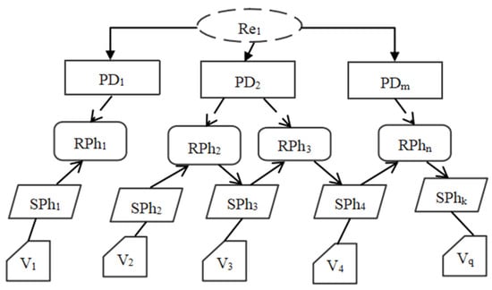
Figure 2.
An example of one sub-problem model in PFM model.
Business process modeling notation (BPMN) contains the top five most frequently used elements in a business process meta-model [33], including events, data, activities, pools and lanes, and sequence flows. Next, this section presents the RBPMN model and the CBPMN model as the execution carrier of the requirements analysis model PFM. The CBPMN model consists of a set of RBPMN models in accordance with the BPMN 2.0 standard [34]. The relationships between PFM, RBPMN, and CBPMN will be established in Section 4.2.
Definition 2.
RBPMN model.
The RBPMN model is a piece of mapping converted directly from a sub-problem model of the PFM model, which can be denoted as a tuple, RBPMN = (E, PL, D, M, In, A, F), where
- (1)
- E is the set of events, in which
① indicates the set of start events,
② indicates the set of intermediate events,
③ indicates the set of end events,
④ There are also other types of event classifications, but all the events in RBPMN can be divided by the location; that is, the event set E consists of a starting event set, an intermediate event set, and an ending event set, which can be written as
- (2)
- PL represents a set of pools and lanes, while a lane refers to the different individuals contained in a pool, and there is at least one pool in a lane,
- (3)
- D is a set of data that indicates information transfer in a pool,
- (4)
- M is a set of messages that indicates information transfer between or among pools,
- (5)
- In is a set of functions, , and its expression is as follows:
which means “ a values c”, and c belongs to data types.
- (6)
- A represents a finite set of activities,
represents the unique identifier of the activities indicates the attribution of the activity, and indicates what the activity does to the related information, ; while the value of In is changed,
- (7)
- F stands for the connected arc set, and
represents the control flow arc set, denotes the data stream arc set, ; : stands for the containing relationships between and flow element; and
Definition 3.
where denotes the set of parallel gateways, denotes the set of exclusive gateways.
where
BPMN collaboration model (CBPMN):
The BPMN collaboration model is a tuple, in which
where
- (1)
- represents an RBPMN model, , , and is the subset of the model.
- (2)
- G is a set of gateways,
① denotes the set of divergent control flow gateways,
② denotes the set of convergent control flow gateways,
- (3)
- represents a set of mapping functions in CBPMN, in which
① indicates the traceable mapping from set to , , where is a set of models, is a vector denoting the relationship from to in , , and.
② represents the gateway pattern, containing the selection of flow direction and the diversion conditions (divergent or convergent and parallel or exclusive type of gateway). Every element of is composed of a two-tuple , where the direction illustrates the change in the flow number, and condition indicates the conditional marking function to choose the next node; .
The CPN model is an executable model for sequential and concurrent systems. As an advanced Petri net, it has mathematical characteristics like reachability and liveness, permitting rigorous quantitative analysis, while its graphical expression makes it easy to understand, and it can model and simulate the system with an initial state; therefore, the CPN model is often used for checking whether the business process model design meets the expected requirements.
Definition 4.
Colored Petri Net [35]:
A CPN model is a tuple,
where
- (1)
- P is a finite set of places, which possess a kind of resource and tokens in a data warehouse waiting for the signal to “move”.
- (2)
- T is a finite set of transitions, which indicate a change in state or the occurrence of an event:
- (3)
- Arc is a finite set of directed arcs,
- (4)
- is an arc expression function, and , written as , and
- (5)
- ∑ is a finite nonempty set of colors, V is a finite set of type variables, and for .
- (6)
- represents a set of mapping functions,
① represents a colored function set that divides places into color set ∑, according to the classification of resources in the simulation,, where is a finite subset of /
② :T→Expr, is the guard function of transition set T, Expr denotes an expression of variables, and
- (7)
- With regard to an identifier set,, the original state defined by user as required is called the initial identifier , and
3.2. PRBC Modeling Framework
The PRBC modeling framework is proposed as shown in Figure 3. This framework is a process of stepwise refinement modeling method, according to the mapping rules and relationship matrices between the PFM model and the business process models.
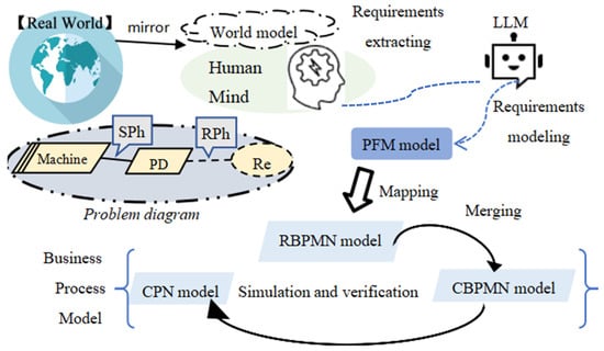
Figure 3.
PRBC modeling framework.
In the problem frames concepts, requirements are classified as a set of phenomena, containing desired relationships, behaviors, events, states, or values in the human mind [13]. To emphasize the system’s relevance to the real world, the first step of iterative business process modeling is to capture the requirement description called the “world model” (which is a “mirror” of the real world compressing common sense into the human mind) and to arrange these phenomena into a requirement model. Every requirement description can be regarded as a fragment of the whole requirement set, and the elements in the problem diagram can be regarded as a sketch of a PFM model.
In the requirement extracting process, to achieve accurate requirement extraction, it is necessary to capture the entities and their relationship in the world model. The world model is a mirror mapping the real world in a human brain [36]. Jay Wright Forrester regarded “the image of the world around us” as a model in our head [37]. “Nobody in his head images all the world, government, or country”; most of the time, people just “select concepts and relationships” and “use those to represent the real system,” which means the world model contains all the entities and relationships relevant to the system under construction. The problem frame depicts the world model through a problem diagram and context frame. Therefore, the PRBC modeling method utilizes LLMs to chat with people to collect dynamic changes in requirements, and PFM models represent the established requirements, while the LLMs extract enough information from the chatting records. Thus, the practical requirements of the real world are mapped onto a series of PFM models, and by a specific mapping function from PFM to RBPMN, the business process structures will catch the constantly changing requirements. The RBPMN model set will be transformed into a CBPMN model after the merging algorithm. As long as the detection of certain properties in the corresponding CPN model simulation is conducted, the CBPMN model can be regarded as a qualified business process model of the initial requirement description.
4. Business Process Iterative Modeling Method
This section describes the business process modeling method. This process consists of three subsections: the collecting and modeling method of requirements, mapping the requirements to business process models, and iterating the method when requirements evolve.
4.1. Requirements’ Collecting and Modeling
As shown in Figure 4, the requirement provider receives a change M from the business environment in flux; the change accumulates into intellectual cognition and then builds the inner world model in the owner’s mind. The large language models (LLMs) will communicate with the requirement provider to extract the necessary information for modeling and convert the requirement description (RD) into requirement details through the interaction of two external modules (Information Extracting and Retrieval) and the internal reasoning module. The obtained model rudiment, called requirement details, will be delivered to the requirement inspector to estimate the quality; then, the inspector will test the output model and determine whether to give feedback to the provider or to confirm the contents as the final outputs in this bout. If the requirement provider receives a piece of feedback, a new change M’ will be imported, and a new cycle will start to build the incremental model.
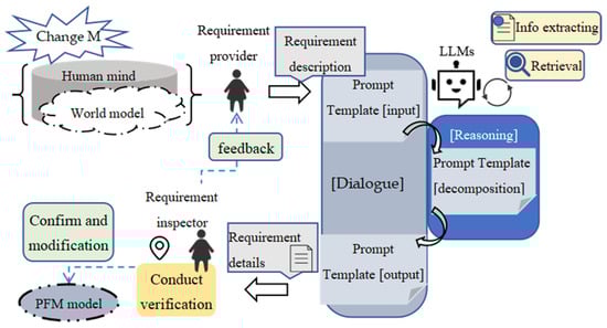
Figure 4.
Requirement collecting and modeling process.
The main part of the requirement modeling paradigm can be generalized as the following three modules: (i) the external function module composed of information extracting and retrieval, which can be respectively instantiated by the Standford CoreNLP and BM25 retrieval algorithm; (ii) the dialogue module based on the generative capability of LLMs, mediated by prompt input in Table 2 and prompt output in Table 3 and (iii) the reasoning module leveraging the generation ability of zero-shot and few-shot Chain-of-Thought (CoT) of LLMs, accomplished through the prompt decomposition shown in Table 4.
Table 2.
The prompt template of input.
Table 3.
The prompt template of output.
Table 4.
The prompt template for decomposition.
After the role modeler accomplishes the transmission to the role trimmer, the requirement details are sufficient for verification and adjustment for the PFM model. To check the practicability of the PFM model, three hierarchies of verification should be taken: the element checking related to structure logic in the PFM model, the rationality verification of the static flow in the CBPMN model, and the executable verification of it.
With the aim of promising the traceability of the original business requirements, a PFM model should abide by certain “rules” represented by increments in the PFM model. The “rules” are summarized from the regularity of the PFM model and the industry common sense in the inspector’s mind; the former is accomplished by the output prompt, while the latter will be discussed in the next section.
4.2. Mapping Requirements to Business Process Models
The PFM architecture links business requirements and their increment to detailed business process implementation elements, which can be transmitted into the CBPMN model through the mapping function , shown in Table 5.
Table 5.
Rules mapping PFM model elements onto RBPMN modules.
The transformation rules between those models are based on semantics.
In order to propagate the requirements, the union of the PFM models is transformed into RBPMN models, complying with a series of relevant matrix calculation rules. According to the construction of the PFM models, the relationship matrix can be defined as follows:
, , the vector , and ;
Thus, the requirements will be transformed into different layer sets through the following calculation matrices, where card(Re) = m, card(PD) = n, card(RPh) = p, card(SPh) = q, and card(V) = k:
That is to say, an inspector can obtain the corresponding RBPMN net modules through the calculation matrices:
In order to implement the rationality verification of the static flow in the CBPMN model, all the RBPMN modules transmitted by calculation matrices will be first merged into a CBPMN model through Algorithm 1.
| Algorithm 1. Net Module Merging Algorithm |
| Input: |
| ; |
| d; {1, 0}; |
| Output |
| (1) Initialize |
| 1. , =; |
| 2. ; 3. i = 1; |
| (2) Merging |
| 4. for #O(m) |
| 5. for (j = i − 1; j > 0; j--) #O(m) |
| 6. if = 0 then #O(n+p+q+k++) |
| 7. ; |
| ; |
| 8. end if |
| 9. if =1 then |
| 10. ; |
| 11. ; ; |
| 12. for(k = 0; k<card(; k++;) #O(log p) |
| 13. for(l = 0; k<card(; l++;) #O(log p) |
| 14. Retrieve all and , |
| 15. .first, .last; |
| 16. .first, .last; |
| 17. [predecessor[, ]].last; |
| 18. [successor[, ]].first; |
| 19. if then |
| 20. ; |
| 21. |
| 22. ; |
| 23. end if |
| 24. if then |
| 25. ; |
| 26. |
| 27. ; |
| 28. end if |
| 29. if then |
| 30. |
| 31. ; |
| 32. end if |
| 33. end do |
| 34. end do |
| 35. end if |
| 36. end do |
| 37. end do |
Algorithm 1 merges a set of RBPMN models into a CBPMN model. Lines 1–3 deal with CBPMN model initialization; Lines 4–37 illustrate the detailed method of merging; the first and second for loops (lines 4–37) list all the models in and combine them from . The first “if” from lines 6 to 8, merges into CBPMN when there are no relations between them, and the second “if” from lines 9 to 35, merges into CBPMN when is related to the previous CBPMN. Lines 14 to 18 retrieve the node sets A and E and find six special kinds of nodes: the first node in sequence excludes the common parts of and , the last node in sequence excludes the common parts of and , the first node in sequence excludes the common parts of and , the last node in sequence excludes the common parts of and , the last node of the common parts of and before their different parts, and the first node of the common parts of and after their different parts. Lines 19 to 32 discuss three conditions of , in order to assign the value to gateway set G and control flow set . The theoretical time complexity of Algorithm 1 is decided by the nested loop structures in lines 4–5 and lines 12–13; thus, the theoretical time complexity of Algorithm 1 is , where m stands for the cardinality of , and p stands for the cardinality of the N set.
As can be seen in Table 6, when the number of nodes exceeds 100,000, the run time of the algorithm significantly increases. This indicates that the algorithm is suitable for large-scale () and part of huge-scale (~) business processes, but for even larger huge-scale (~ business processes with more than 100,000, nodes, optimization or the use of approximate algorithms may be necessary.
Table 6.
Theoretical time complexity analysis of Algorithm 1.
4.3. Model Verification and Iteration of Incremental Requirement
After executing Algorithm 1, the requirement inspector will get an untested CBPMN model; thus, the obtained CBPMN model will be verified through two procedures. One is the static flow checking in Algorithm 2. Static flow checking will detect the flow in the CBPMN model to confirm whether there is any isolated node in the directed acyclic graph of CBPMN.
Algorithm 2 will recognize all the isolated nodes and redundant nodes in the obtained CBPMN model. Lines 2–3 retrieve all the nodes and calculate the in-degree and out-degree of each node; lines 5–12 traverse all the classifications to get the isolated nodes, invalid start nodes, and invalid end nodes; lines 13–27 divide the selected nodes into different classifications, and lines 28–29 output all node errors.
Following the steps above, the requirement collector obtains the fundamental CBPMN model from Table 5 and gains the corresponding CPN model according to Table 7: the mapping rules of the model CBPMN transforming into the CPN model are listed in Table 7. Then, the multiple turns of dialogue transfer the incremental requirement up to date. Thus, the next subsection will elaborate on the method of handling the incremental task and adding requirements to the business process that was already built.
Table 7.
CBPMN model elements mapping onto CPN net modules rules.
| Algorithm 2. CBPMN Net Modules Checking Algorithm |
| Input: |
| Output: All flow errors |
| (1) Initialize |
| 1. ; |
| 2. Retrieve all nodes in CBPMN, |
| 3. Calculate the in_degree(x) and out_degree(x) of E, A, D, M and G. |
| 4. , |
| ; |
| (2) verification |
| 5. for each node x in X do |
| 6. and out_degree(x) then |
| 7. ; |
| 8. then |
| 9. ; |
| 10. then |
| 11. ; |
| 12. end for |
| 13. for each PL do |
| 14. then |
| 15. ; //Find all start nodes in PL |
| 16. then |
| 17. ; //Find all end nodes in PL |
| 18. if PL has no sub-L then |
| 19. then |
| 20. |
| 21. then |
| 22. |
| 23. then |
| 24. ; |
| 25. then |
| 26. ; |
| 27. end for |
| 28. Print all isolated_nodes, invalid_start_nodes, invalid_end_nodes; |
| 29. Print all redundant_start_E, redundant_end_E; |
Whether the CBPMN model fulfills the original requirements can be detected by checking the condition of the target input and output modules in the CPN model. Thus, according to the traceability of the PRBC modeling approach, to verify the realizability of requirements, the reachability of CPN shall be tested.
Definition 5.
Reachability of CPN Model
Let be a CPN model. If there exists a t∈ T such that [t > , then is said to be directly reachable from . If there exists a sequence of transitions , , …, and a sequence of identifiers , , …, such that [ > [ > … > [ > , then is said to be reachable from . “[t > ” means that identifier ““ will change to after transition t is fired.
If an arbitrary belonging to the set I of CPN is reachable from the initial identifier , then the reachability of CPN meets the standard, and the corresponding CBPMN model is executable.
When addressing a complex problem involving many nodes, the overall requirement description is always divided into several modules or function points, and each part is analyzed and designed separately. The PRBC modeling approach allows the incremental improvement of requirements and helps to accelerate the requirement modeling process. By leveraging human–computer collaboration, the requirements can be optimized continuously. As outlined in Figure 5, the requirement increment will be transformed into PFM models through the prompts provided in Table 2, Table 3 and Table 4; then, the new set of PFM models will be altered into a RBPMN model set. Subsequently, Algorithm 1 takes this RBPMN set and the previous CBPMN model as its input (where the previous CBPMN is assigned as the initial value in Lines 1–2) to generate a new CBPMN model through merging. The following verification results of Algorithm 2 and CPN simulation will decide the inspector’s choice for the new CBPMN model to get feedback or a confirmation.
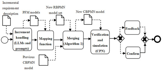
Figure 5.
Business process iterative modeling method.
5. Experimental Design and Case Study
This paper proposes the PRBC, a modeling and verification framework for business process models under the requirement perspective. Compared with other methods, this method can generate a higher quality BPMN model through chatting with the requirement provider. To prove this conclusion, two research questions were delivered with a corresponding case study to demonstrate the validity of the PRBC.
Research question 1: How does the quality of the PFM model generated by the PRBC in the requirement modeling process compare to other methods? In Section 5.2, we calculate three indices of the generated PFM models utilizing the PRBC method on five cases and conduct comparative experiments with three other automated methods.
Research question 2: Can the PRBC method convert the requirements description in dialogue into a complete CBPMN model that meets the reachability standard in definition 5? Question 2 aims to prove the validity of the generated CBPMN. In Section 5.3, we built an online car-hailing CBPMN model through a set of tools that automate the generation of the model and verification.
Before the case study, Section 5.1 will introduce the configuration settings in the experiments.
5.1. Configuration Settings in the Experiments
- (1)
- Cases used for experiments. Five publicly available cases were adopted as a raw data set for evaluating the quality of the requirement modeling part in PRBC. The five cases are the Automated Teller Machine (ATM) [38], Data Set Searching System (DSSS) [39], Elevator System (ES) [40], SmartNet System (SNS) [41], and CamperPlus (CPs) [42]. Each case is composed of a detailed requirement description and a standardized requirement model. In addition, for research question 2, an actual application system based on the comprehensive requirement of a car-hailing system [43,44,45] is chosen as the research case for modeling and verification.
- (2)
- Baseline method. This paper employed three automated modeling approaches as the baseline method to compare with the PRBC; the three methods are introduced as follows:
- (1)
- The GSD [38] method generates a sequence diagram by defining NLP rules extracting actors, senders, and receivers from processed natural language;
- (2)
- The AEPD [46] method generates a problem diagram through function modules entity extractor, relation predictor, and element assembler;
- (3)
- The TtMT [47] method adjusts the operation in natural language processing while extracting and selecting information and generates models conforming to the SysML standard, such as a class diagram from input textual requirements.
- (3)
- Configuration settings of models and algorithm in the PRBC framework.
The technical implementation routine is shown in Figure 6. This paper uses two open-source LLMs, DeepSeek-V3 for chatting and Deepseek-R1 for model reasoning. DeepSeek-V3 supports the dialogue module and can generate responses according to prompts in Table 2 and Table 4; the chatting records will be transformed into JSON format and sent to an NLP module named Stanford NLP, which can be invoked through Python 3.14 after the Stanford CoreNLP Python interface is installed; the keywords will be sorted by algorithm BM25, which is available for download at https://github.com/xhluca/bm25s (accessed 1 December 2024), and the selected phrases and keywords will be packed together and sent to Deepseek-R1, which integrates a web searching function to build the PFM model according to the prompts in Table 3 and Table 4. The generated PFM model will be validated by JSON Schema and sent to Plant Text to implement the visualization of the PFM model. The mapping function will transform PFM to RBPMN models through a JSON2BPMN converter (accessed on 12 September 2024, from https://github.com/taoxiaotao6/bpmn_converter), while the BPMN editor (accessed on 12 December 2024, from https://bpmn.io/toolkit/bPMn-js/) can export BPMN diagrams and the corresponding XML format. The PNML is an XML-based markup language, which uses tags to describe the data. Thus, based on the mapping function ϕ and a BPMN2CPN script, the CBPMN can be transformed to a CPN model through Java 8.
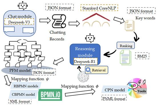
Figure 6.
PRBC technical realization process.
5.2. Requirement Modeling Quality Evaluation
In order to evaluate the quality of the requirement model PFM generated by the LLMs and prompts in Section 4.1, this experiment chooses to compare the PRBC with three advanced requirements automatic modeling methods introduced in Section 5.1 (2) on five publicly available cases in Section 5.1 (1), and it calculates the accuracy, recall, and F1 value of the requirements’ modeling elements generated from the requirements’ description of the provider.
- (1)
- Experiment procedure: The experiment starts by tuning two hyperparameters (the temperature and the max tokens) in DeepSeek-V3 and Deepseek-R1. With the prompt templates from Table 2, Table 3 and Table 4, the chat module asks the provider questions, according to the model elements and collects answers to construct the requirement models. As for the other three methods, we maintain the infrastructure of prompts and change the model elements marked by the symbol “<>”. To keep the initial input information amount at the same quantity level, the requirement description of every case is simplified to a document, the provider will answer the questions according to the same document, and the number of interaction rounds between the provider and chat module is capped at 10. The record of dialogue will be divided into pieces related to different PFM model elements through two external function modules, the information extracting module through the ranking and retrieving module, and the processed package will be processed in Deepseek-R1 to generate the model in JSON format.
- (2)
- Index chosen and calculation formula: Due to the difference among the output formats of the methods mentioned above, this paper selects the precision, recall, and F1-score as the evaluation metrics to guarantee the equity in the experiment.
- (3)
- Hyperparameter tuning: While keeping the prompt templates, case sets, the chatting and reasoning LLMs, and the input information quantity constant, we performed hyperparameter tuning manually for the temperature over the range of (0, 1) and max_tokens over the range of (500, 4000). The experiment finds that the best temperature of Deepseek-R1 is 0.5m and the max_tokens is 2048 tokens. When the two hyperparameters are set to the above value, the calculation results of the three indices for the requirement models generated by the PRBC and three other methods are shown in Table 8.
Table 8. Evaluation results between PRBC and other methods on modeling quality.
- (4)
- Results analysis: The three indices are calculated by invoking Scikit-learn via Python. As can be seen in Table 8, except for yielding comparable results to the GSD method on the ATM case, the PRBC achieved higher performance on the recall value over other methods; similarly, apart from achieving comparable results to the AEPD method on the CP case, the PRBC markedly outperforms other baseline methods. Additionally, the PRBC demonstrates superior performance over other methods on the F1-score, maintaining an improvement difference value over 3% (at least). Thus, across multiple cases, the PRBC establishes a clear and consistent advantage over the baseline, as evidenced by its results in all three key metrics.
- (5)
- Statistical significance: The permutation test is conducted to assess the uncertainty of results in Table 8. The p-value is 0.049.
- (6)
- Impacts of dialogue length: To explore how the method performs in longer dialogue, the DSSS case was chosen for the experiment, with the number of dialogue rounds ranging from 5 to 30. The benchmark system uses only the original history, and the enhanced memory system uses external memory. It can be clearly seen from Figure 7 that the two curves of the benchmark system show a significant and continuous decline, while the enhanced system is significantly more gradual. That indicates the context loss impacts the model consistency over the text length.
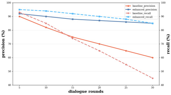 Figure 7. Performance trends in long conversation.
5.3. Verification of the Business Process Model
This section will represent the modeling process of a CBPMN model, as well as the rationality verification of the static flow and the executable verification of it through a car-hailing system case.
- (1)
- Case introduction: With the rise of private car ownership, online car-hailing has emerged as a mainstream option for transportation. It is now common to use mobile apps and high-speed networks to benefit from this convenience. Given its prevalence as a ride-hailing platform, this paper employs an example based on the Didi Chuxing system to demonstrate the feasibility of our approach.
- (2)
- Case modeling: The requirements description of car-hailing was put into the LLMs through the dialogue; then, the LLMs generated the PFM model description according to the output format, which is partially shown in Table 9. This can be transformed into a PFM diagram through tool Plant Text, shown in Figure 8a,b.
Table 9. Partial output result of car-hailing system requirement model.
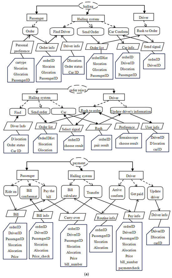
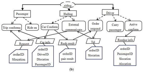 Figure 8. (a) The PFM model of the car-hailing system. (b). The residue PFM model of the car-hailing system.
 - (3)
- Rationale verification of static flow: The element set of PFM was converted into the corresponding RBPMN models in Figure 9, according to the mapping rules shown in Table 5. Then, the four RBPMN set groups were combined according to Algorithm 1, and the output model is shown in Figure 10. The result of Algorithm 2 illustrated that there are two isolated nodes (“Ride on” and “Carry passenger”) in the hailing system CBPMN model.
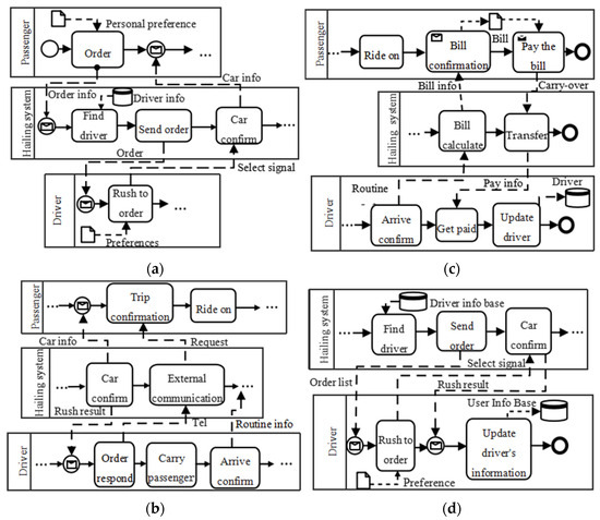 Figure 9. The RBPMN models corresponding to PFM models. (a) The hailing RBPMN model; (b) the riding RBPMN model; (c) the payment RBPMN model; (d) the order reject RBPMN model.
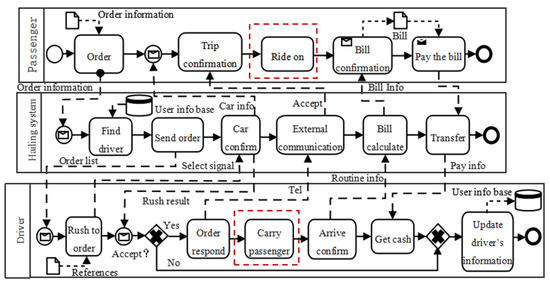 Figure 10. The complete CBPMN model of the hailing system.
 - (4)
- The executable verification: Following the mapping rule in Table 7, we converted the requirement description of the car-hailing system into an executable CPN model. Next, the obtained CPN model was verified by checking the reachability and liveness through CPN Tools 4.0. From the condition of the simulation, we find that there is no dead transition, dead lock, live lock, or dead markings in the CPN model, which can be proven by the state–space report shown in Table 10. Based on the simulation result shown in Figure 11, the operation path and results of the model met the requirements of the initial problem diagram and PFM model.
Table 10. State–space report of the car-hailing system CPN model.
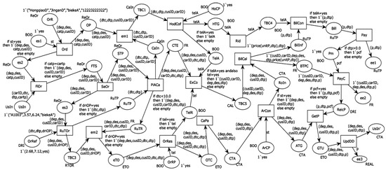 Figure 11. The simulation model of the car-hailing system in CPN tools.
Therefore, after the analysis of the simulation result and the observation of the actual operation process, it is demonstrated that the business process iterative modeling approach is effective.
6. Conclusions
The lack of systematic iterative requirement modeling methods and tools hampers business process modeling. To address this: (1) we propose a framework of iterative business process modeling to integrate the tools from the requirement model establishment to business process model execution and to bridge the gap between requirement elicitation and business process modeling and verification; (2) we present a requirement model based on the automatic language processing ability of large language models to reduce the labor; (3) we verify the feasibility and usability of the proposed method by experiments of simulation and verification; (4) we put forward two algorithms, one for generating the CBPMN model from the RBPMN model set and another for verification of the newly generated CBPMN model.
The iterative requirement modeling method embraces the concept of continuous integration, effectively combining requirements analysis, design, simulation, and verification to create a comprehensive business process modeling routine. This approach addresses the inflexibility and rigidity often encountered in verification within traditional business process modeling and requirements verification.
In this paper, due to the space constraints and thematic considerations, the formal consistency of verification has not been discussed. Additionally, the behavior verification methods and standards of requirements will be investigated in the follow-up study.
Author Contributions
Conceptualization, H.X. and F.N.; Formal analysis, H.X.; Funding acquisition, F.N. and J.L.; Investigation, R.F. and Y.D.; Methodology, H.X.; Project administration, H.X.; Resources, H.X.; Supervision, F.N. and J.L.; Validation, H.X.; Visualization, R.F. and Y.D.; Writing—original draft, H.X.; Writing—review and editing, H.X. All authors have read and agreed to the published version of the manuscript.
Funding
This work was supported by the National Natural Science Foundation of China (Grant Number: 12371508), the Industry-University Cooperative Education Project of the Ministry of Education of China (Grant Number: 241103760141654), and the Shanghai University Student Innovation and Entrepreneurship Training Program (Grant Numbers: XJ2025085 and XJ2025167).
Institutional Review Board Statement
Not applicable.
Informed Consent Statement
Not applicable.
Data Availability Statement
The raw data supporting the conclusions of this article will be made available by the authors on request.
Conflicts of Interest
The authors declare no conflicts of interest.
References
- Lara Machado, P.; van de Ven, M.; Aysolmaz, B.; Athanasopoulou, A.; Ozkan, B.; Turetken, O. Methods that bridge business models and business processes: A synthesis of the literature. Bus. Process Manag. J. 2023, 29, 48–74. [Google Scholar] [CrossRef]
- Das, S.; Deb, N.; Cortesi, A.; Chaki, N. Extracting goal models from natural language requirement specifications. J. Syst. Softw. 2024, 211, 111981. [Google Scholar] [CrossRef]
- Kolligs, J.; Thomas, L.D. On the Viability of Diagrams and Drawings as System Requirements. Systems 2023, 11, 176. [Google Scholar] [CrossRef]
- Liu, X.; Liu, Y.; Zhuang, Y.; Hou, W. UCD-LLM: A use case diagram requirement modeling multi-agent framework with large language model. Inf. Softw. Technol. 2025, 190, 107955. [Google Scholar] [CrossRef]
- Necula, S.-C.; Dumitriu, F.; Greavu-Șerban, V. A Systematic Literature Review on Using Natural Language Processing in Software Requirements Engineering. Electronics 2024, 13, 2055. [Google Scholar] [CrossRef]
- Badakhshan, P.; Conboy, K.; Grisold, T.; vom Brocke, J. Agile business process management: A systematic literature review and an integrated framework. Bus. Process Manag. J. 2020, 26, 1505–1523. [Google Scholar] [CrossRef]
- Arias-Pérez, J.; Chacón-Henao, J.; López-Zapata, E. Unlocking agility: Trapped in the antagonism between co-innovation in digital platforms, business analytics capability and external pressure for AI adoption? Bus. Process Manag. J. 2023, 29, 1791–1809. [Google Scholar] [CrossRef]
- Mielcarek, P.; Chwiłkowska-Kubala, A.; Cyfert, S.; Chomicki, M. Are agile organisations more process mature? Business process agility and process maturity as leverage for business performance. Bus. Process Manag. J. 2025, 31, 2668–2687. [Google Scholar] [CrossRef]
- Tupia-Astoray, A.; Laberiano-Andrade, A. Implementation of an e-Commerce System for the Automation and Improvement of Commercial Management at a Business Level. Int. J. Adv. Comput. Sci. Appl. 2021, 12, 672–678. [Google Scholar] [CrossRef]
- Sarr, L.A.; Ayite, P.K.; Barthe-Delanoë, A.M.; Bork, D.; Macé-Ramète, G.; Benaben, F. Towards the Integration of Conversational Agents Through a Social Media Platform to Enhance the Agility of BPM. In Proceedings of the 25th IFIP WG 5.5 Working Conference on Virtual Enterprises, Albi, France, 28–30 October 2024; Springer: Cham, Switzerland, 2024; Volume 9, pp. 36–48. [Google Scholar]
- Meziani, R.; Imad, S. Towards a collaborative business process management methodology. In Proceedings of the 2011 International Conference on Multimedia Computing and Systems, Ouarzazate, Morocco, 7–9 April 2011. [Google Scholar]
- Lederer, M.; Julia, T. Organizing a Self-organized Team: Towards a Maturity Model for Agile Business Process Management. In Proceedings of the 13th International Conference on Subject-Oriented Business Process Management, Karlsruhe, Germany, 29 June–1 July 2022; Springer: Cham, Switzerland, 2022. [Google Scholar]
- Von Rosing, M.; Henrik Von, S.; August-Wilhelm, S. The Complete Business Process Handbook: Body of Knowledge from Process Modeling to BPM; Morgan Kaufmann: Burlington, MA, USA, 2014; Volume 1. [Google Scholar]
- Pham, C.T.A.; Magistretti, S.; Dell’Era, C. How do you frame ill-defined problems? A study on creative logics in action. Creat. Innov. Manag. 2023, 32, 493–516. [Google Scholar] [CrossRef]
- Intrigila, B.; Della Penna, G.; D’Ambrogio, A. A lightweight BPMN extension for business process-oriented requirements engineering. Computers 2021, 10, 171. [Google Scholar] [CrossRef]
- Jackson, M. Problem frames and software engineering. Inf. Softw. Technol. 2005, 47, 903–912. [Google Scholar] [CrossRef]
- Hoy, Z.; Xu, M. Agile software requirements engineering challenges-solutions—A conceptual framework from systematic literature review. Information 2023, 14, 322. [Google Scholar] [CrossRef]
- Ruan, K.; Chen, X.; Jin, Z. Requirements Modeling Aided by ChatGPT: An Experience in Embedded Systems. In Proceedings of the 2023 IEEE 31st International Requirements Engineering Conference Workshops (REW), Hannover, Germany, 4–5 September 2023. [Google Scholar]
- Liu, Y.; Jean-Michel, B. Modeling and verification of natural language requirements based on states and modes. Form. Asp. Comput. 2024, 36, 1–47. [Google Scholar] [CrossRef]
- Uygun, Y.; Momodu, V. Local large language models to simplify requirement engineering documents in the automotive industry. Prod. Manuf. Res. 2024, 12, 2375296. [Google Scholar] [CrossRef]
- Abdeen, W.; Xingru, C.; Michael, U. An approach for performance requirements verification and test environments generation. Requir. Eng. 2023, 28, 117–144. [Google Scholar] [CrossRef]
- Yang, Y.; Zeng, B.; Gao, J. RM4ML: Requirements model for machine learning-enabled software systems. Requir. Eng. 2024, 30, 1–33. [Google Scholar] [CrossRef]
- Gu, P.; Zhang, Y.; Chen, Z.; Zhao, C.; Xie, K.; Wu, Z.; Zhang, L. X-RMTV: An Integrated Approach for Requirement Modeling, Traceability Management, and Verification in MBSE. Systems 2024, 12, 443. [Google Scholar] [CrossRef]
- Besnard, V.; Teodorov, C.; Jouault, F.; Brun, M.; Dhaussy, P. Unified verification and monitoring of executable UML specifications: A transformation-free approach. Sof. Sys. Mod. 2021, 20, 1825–1855. [Google Scholar] [CrossRef]
- Atoum, I. Measurement of key performance indicators of user experience based on software requirements. Sci. Comput. Program. 2023, 226, 102929. [Google Scholar] [CrossRef]
- Corradini, F.; Fornari, F.; Polini, A.; Re, B.; Tiezzi, F.; Vandin, A. A formal approach for the analysis of BPMN collaboration models. J. Syst. Softw. 2021, 180, 111007. [Google Scholar] [CrossRef]
- Dechsupa, C.; Wiwat, V.; Thongtak, A. Transformation of the BPMN design model into a colored Petri net using the partitioning approach. IEEE Access 2018, 6, 38421–38436. [Google Scholar] [CrossRef]
- Cheng, L.; van Dongen, B.F.; van der Aalst, W.M. Scalable discovery of hybrid process models in a cloud computing environment. IEEE Trans. Serv. Comput. 2019, 13, 368–380. [Google Scholar] [CrossRef]
- Corradini, F.; Morichetta, A.; Muzi, C.; Re, B.; Tiezzi, F. Well-structuredness, safeness and soundness: A formal classification of BPMN collaborations. J. Log. Algebr. Methods Program. 2021, 119, 100630. [Google Scholar] [CrossRef]
- Popic, S.; Teslic, N.; Bjelica, M.Z. Simple Framework for Efficient Development of the Functional Requirement Verification-Specific Language. Adv. Electr. Comput. Eng. 2021, 21, 11–20. [Google Scholar] [CrossRef]
- Ferrari, A.; Spoletini, P. Formal requirements engineering and large language models: A two-way roadmap. Inf. Softw. Technol. 2025, 181, 107697. [Google Scholar] [CrossRef]
- Koboyatshwene, T.; Ayalew, Y. Requirements Traceability: A Systematic Literature Review. In Proceedings of the 40th ACM/SIGAPP Symposium on Applied Computing, Catania, Italy, 31 March–4 April 2025; pp. 1509–1513. [Google Scholar]
- Adamo, G.; Chiara, G.; Chiara, D.F. What is a process model composed of A systematic literature review of meta-models in BPM. Softw. Syst. Model. 2021, 20, 1215–1243. [Google Scholar] [CrossRef]
- Rosing, M.V.; White, S.; Cummins, F. Business Process Model and Notation (BPMN); Springer: Berlin/Heidelberg, Germany, 2015. [Google Scholar]
- Jensen, K.; Lars, M.K.; Lisa, W. Coloured Petri Nets and CPN Tools for modelling and validation of concurrent systems. Int. J. Softw. Tools Technol. Transf. 2007, 9, 213–254. [Google Scholar] [CrossRef]
- Ha, D.; Jürgen, S. World models. arXiv 2018, arXiv:1803.10122. [Google Scholar]
- Lane, D.C.; Etiënne, A.R. Towards a behavioural system dynamics: Exploring its scope and delineating its promise. Eur. J. Oper. Res. 2023, 306, 777–794. [Google Scholar] [CrossRef]
- Jahan, M.; Abad, Z.S.H.; Far, B. Generating Sequence Diagram from Natural Language Requirements. In Proceedings of the 2021 IEEE 29th International Requirements Engineering Conference Workshops, Notre Dame, IN, USA, 20–24 September 2021. [Google Scholar]
- Munima, J.; Mohammad, M.H.; Reza, G. Automated Derivation of UML Sequence Diagrams from User Stories: Unleashing the Power of Generative AI vs. a Rule-Based Approach. In Proceedings of the ACM/IEEE 27th International Conference on Model Driven Engineering Languages and Systems (MODELS ‘24), New York, NY, USA, 22–27 September 2024. [Google Scholar]
- Ferrari, A.; Abualhaijal, S.; Arora, C. Model Generation with LLMs: From Requirements to UML Sequence Diagrams. In Proceedings of the 2024 IEEE 32nd International Requirements Engineering Conference Workshops (REW), Reykjavik, Iceland, 24–25 June 2024. [Google Scholar]
- Sonawane, S.; Puthran, S. Extracting use case elements from requirement documents: A natural language processing approach. Requir. Eng. 2025, 30, 283–310. [Google Scholar] [CrossRef]
- Herwanto, G.B.; Quirchmayr, G.; Tjoa, A.M. Leveraging NLP techniques for privacy requirements engineering in user stories. IEEE Access 2024, 12, 22167–22189. [Google Scholar] [CrossRef]
- Zhao, H.; Zhao, P.; Jiang, S. Examining the dynamic engagement process of passengers in online car-hailing system: A view of user value. Transp. Plan. Technol. 2025, 48, 293–312. [Google Scholar] [CrossRef]
- Wang, Z.; Zang, L.; Tang, Y.; Shen, Y.; Wu, Z. An intelligent networked car-hailing system based on the multi sensor fusion and UWB positioning technology under complex scenes condition. World Electr. Veh. J. 2021, 12, 135. [Google Scholar] [CrossRef]
- Lan, S.; Yang, C.; Chen, C.H. Online car-hailing system performance analysis based on Bayesian network. IEEE Access 2019, 7, 101195–101212. [Google Scholar] [CrossRef]
- Jin, D.; Chunhui, W.; Zhi, J. Automating Extraction of Problem Diagrams from Natural Language Requirement Documents. In Proceedings of the 2023 IEEE 31st International Requirements Engineering Conference Workshops (REW), Hannover, Germany, 4–5 September 2023. [Google Scholar]
- Akundi, A.; Ontiveros, J.; Luna, S. Text-to-model transformation: Natural language-based model generation framework. Systems 2024, 12, 369. [Google Scholar] [CrossRef]


Disclaimer/Publisher’s Note: The statements, opinions and data contained in all publications are solely those of the individual author(s) and contributor(s) and not of MDPI and/or the editor(s). MDPI and/or the editor(s) disclaim responsibility for any injury to people or property resulting from any ideas, methods, instructions or products referred to in the content. |
© 2026 by the authors. Licensee MDPI, Basel, Switzerland. This article is an open access article distributed under the terms and conditions of the Creative Commons Attribution (CC BY) license.