Abstract
Surface subsidence caused by high-intensity coal mining in the western mining area will have a negative impact on the environment. Mining subsidence has the characteristics of large scope, long duration, and strong destructiveness. In order to deeply understand the law of surface movement and deformation under the high-intensity mining of coal mines in western China, taking the Caojiatan 122,106 working face as an example, this study was conducted to obtain the surface movement characteristics and law by the method of surface rock movement measurement. The results showed that the surface subsidence in this study is mainly divided into three stages: start-up stage, active stage, and recession stage, with the active stage characterized by abrupt and intensive settlement. The maximum measured subsidence reached 4.173 m along the strike and 3.350 m along the dip. Numerical simulations further demonstrated strong vertical connectivity within the overburden, with surface subsidence area covering approximately 2/3 of the direct roof area. The predicted maximum subsidence values from simulation were 4.21 m (strike) and 3.36 m (dip), closely aligning with field data. A probability integral model was calibrated using observed data, yielding key parameters: subsidence coefficient = 0.537, main influence angle tangent = 4.435, horizontal movement coefficient = 0.20, inflection point offset = 76.90 m, and propagation angle = 86.2°. This study provides a validated methodology for predicting surface deformation in western mining areas and offers practical insights for subsidence mitigation and land restoration.
1. Introduction
China has abundant coal resources. With the rapid development of new energy, the coal resource still occupies a dominant position in energy resources. It plays an irreplaceable role in the economic development of China [1,2,3]. In recent years, with the development and utilization of coal resources, the focus of coal development has gradually shifted to western China, such as Shaanxi, Xinjiang, and other regions. The coal seams in the western region have better occurrence conditions and it is suitable to adopt high-intensity mining methods. However, most of the western regions are arid and semi-arid, and they belong to an ecologically fragile area. Issues such as high stress and pressure due to intensive mining can have various negative adverse effects on the environment [4]. The most significant problem is the surface subsidence, which not only destroys the ecological environment, but also destroys the buildings on the ground [5,6,7,8]. A great deal of research has been conducted on surface subsidence caused by mining since the 1960s, especially in eastern China [9,10]. During steep coal seam mining in a community in Huating County, Gansu Province, severe surface collapse and ground fissures occurred, with a maximum cumulative subsidence of 2130 mm. The deformation was induced by the destruction of the overlying loess layer and unstable strata movement under high-intensity mining in the loess hilly region. Emergency measures included deploying MSPS numerical simulation to predict deformation trends and implementing targeted reinforcement for residential buildings in the collapse-affected area by Li et al. [11]. Mining-induced goaf collapse affected the 28#–35# iron towers of the 35 kV Linta Line in Yijinhuoluo Banner, Ordos, causing tower foundation settlement, tilting, and conductor displacement. The root cause was reduced soil bearing capacity due to loose surface structure in the long-term mining area. Emergency responses involved constructing cast-in-place pile reinforcement for tower foundations and installing adjustable bolts to dynamically regulate structural stability during mining-induced deformation [12]. However, there are few studies on the surface subsidence caused by high-intensity mining in the western ecologically fragile areas. Therefore, it is of great significance to explore the law of surface movement and deformation caused by high-intensity mining in western mining areas for surface ecological protection and post-mining land restoration.
In response to the challenges of surface deformation and subsidence, research both domestically and internationally has transitioned from traditional methods towards a modernized monitoring technology system characterized by multi-dimensionality, real-time capability, and intelligence. For large-area monitoring, time-series InSAR techniques, particularly Distributed Scatterer InSAR (DS-InSAR), have enabled the capture of surface deformation with millimeter-level accuracy. Their effective application in complex mining areas of western China, such as those with loess cover, has successfully revealed the spatiotemporal evolution patterns of subsidence basins by Tang et al. [13]. Regarding real-time and continuous monitoring of critical zones, multi-constellation GNSS networks, leveraging their millimeter-level positioning accuracy and adjustable sampling rates, have become a core tool for real-time early warning and stability assessment [14,15]. At the level of detailed identification and investigation, UAV-borne LiDAR coupled with high-resolution imagery and artificial intelligence algorithms allows for the rapid acquisition of centimeter-level 3D terrain data and the automated identification of surface fissures and collapses, improving monitoring efficiency severalfold compared to manual surveys. Furthermore, to investigate the mechanisms of deep strata movement, geophysical exploration techniques like Controlled-Source Audio-Frequency Magnetotelluric (CSAMT) are employed for the non-invasive assessment of deep rock mass quality and structure, offering a new technological approach for predicting potential subsidence pathways by Liu et al. [16]. These technologies are progressively evolving from standalone applications towards synergistic integration, building an integrated space–air–ground monitoring framework. This provides a solid data foundation and technical support for in-depth research on the laws of surface movement and disaster prevention and control under high-intensity mining conditions in western China by Hasan et al. [17].
In a numerical simulation study by Osborne et al. [18], based on the measured data, computer modeling and prediction were carried out to analyze the subsidence development trend, providing a research example combining measured and simulated methods for the surface movement control of subsequent mining in this area. In the field of actual measurement research, the total station and GPS were jointly used for the surface horizontal displacement monitoring of a mined-out area by Zhang [19], and the triangle elevation method was adopted to make the vertical displacement monitoring, thus obtaining the horizontal displacement value and sinking cumulants of the cavity surface. Aiming at the surface movement problem of the repeated mining of multiple coal seams in soft rock strata, Visser A T et al. [20] analyzed the mechanism of rock layer movement through numerical simulation. Combined with the field-measured data, it revealed the superimposed effect of surface subsidence in the mining of multiple coal seams in soft rock strata, providing a reference for the mining of similar soft rock mining areas in the west. Based on the surface movement observation, the mining strata movement parameters were analyzed and the failure mechanism of surface movement and deformation were studied by Yu et al. Karpuz C et al. [21] constructed a model that conforms to the actual geological conditions by using numerical simulation software, compared and analyzed the measured and simulation results, and clarified the influence mechanism of geological structures such as faults and folds on the surface movement law [22] for the mining of shallow coal seam and thick loose bed. The influence of coal face length on surface movement and deformation in the condition of large height mining was studied by Xiong et al. [23] through numerical simulation, theoretical analysis, and in situ measurement. Based on the combination of elastic foundation beams and volume-invariant transfer principles, Guo et al. [24] proposed a prediction model to predict the surface subsidence caused by dense solid backfilling mining. Dudek M et al. [25] constructed a numerical model by using the finite element method combined with Python3.10. It calibrated the mechanical parameters of rock strata through the geological survey data and measurement data of the mining area, and compared the simulated surface deformation results with the measured values, which significantly improved the accuracy of surface deformation prediction in mining. Combining monitoring data with numerical simulation, multi-source monitoring data identify high-risk zones, guiding the precise implementation of prevention measures. For example, InSAR deformation fields and UAV-LiDAR point clouds are used to map concentrated fissure zones (fissure density > 3 per 100 m2), where additional protective pillars (width increased by 10–15 m) are reserved. Historical monitoring data refine prevention strategies and mining parameters. For example, an analysis of 3-year GNSS and InSAR data in the Ordos mining area revealed that subsidence velocity is positively correlated with mining height (R2 = 0.87)—leading to a revision of the maximum allowable mining height from 22 m to 18 m in loess-covered areas. CSAMT-derived rock mass integrity data optimize protective pillar dimensions: for RQD = 50–70%, pillar width is increased by 20% compared to RQD > 70%. Additionally, long-term monitoring data are used to validate numerical simulation models, improving the accuracy of subsidence prediction for future mining areas.
At present, a growing number of studies focus on the surface subsidence caused by coal mining in the eastern mining area [26], and there is less research on the law of land subsidence caused by high-intensity mining in the western environmentally fragile area [11,27]. At the same time, due to the mining methods and environmental problems, the movement law of the overlying rock has various characteristics, and the surface deformation law is also different. To address this gap, this study focuses on the Caojiatan 122,106 working face in western China. We conducted a comprehensive field campaign using a designed surface observation network to capture the complete subsidence process. The data were analyzed to quantify deformation parameters and subsidence stages. Furthermore, we employed the discrete element method (UDEC) to simulate the mechanisms of overburden failure, explicitly modeling discontinuous rock mass behavior. The objectives are to carry out the following: (1) delineate the stage-specific characteristics of surface movement under western mining conditions; (2) calibrate reliable parameters for the probability integral prediction method; (3) reveal the mechanism of vertical subsidence transmission through numerical simulation; and (4) establish a validated modeling framework that links monitoring data with the assessment of prevention strategies. The outcomes aim to provide a scientific basis for subsidence hazard mitigation and ecological protection in similar mining regions.
2. Research Background
2.1. Regional Geomorphology and Geological Conditions
There are no villages, cultivated land, or artificial buildings in other areas of the working face. The terrain gradually decreased from southwest to northeast. At about 1200 m near the stop line, a temporary gangue turnover site was established on the surface. The corresponding ground position of the open cut is about 150~270 m southwest. There are two seasonal gully flows passing through from northwest to southeast, and some housing construction. Working face mining leads to ground subsidence, which has a certain impact on houses and water supply wells, as shown in Figure 1.
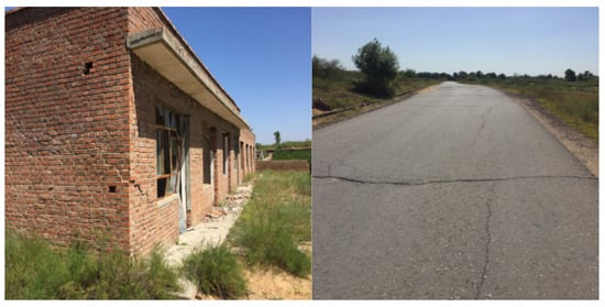
Figure 1.
Influence of surface subsidence on roads and buildings.
2.2. Characteristics of Coal Seam and Cover Rock
The coal seam of the working face is a 2-2 coal seam, which is located at the top of the fourth section of the Yan’an formation. The coal seam is nearly horizontal, the coal seam thickness is 6.29~12.7 m, and the mining thickness of the working face is 7 m. The geological structure of the coal seam in the mining area of this working face is simple, and there is a thick layer of siltstone gangue in the local area. The properties of the coal seam roof and floor are shown in Table 1.

Table 1.
Characteristics of roof and floor of 122,106 working face.
2.3. Comparison Between Eastern and Western Mining Regions and Technology Transfer Potential
The eastern mining areas of China (e.g., Shanxi, Shandong) are characterized by deeper coal seams, thicker overburden, and higher groundwater levels, resulting in slower and more continuous surface subsidence. In contrast, western regions (e.g., Shaanxi, Inner Mongolia) feature shallow seams, thinner overburden, and arid climates, leading to rapid, abrupt, and vertically connected subsidence patterns. Monitoring techniques developed in the east, such as long-term GPS networks and theoretical models based on viscoelastic strata behavior, may not directly apply to the west due to differing geological and hydrological conditions. However, advanced numerical tools (e.g., UDEC, FLAC3D) and real-time monitoring platforms can be adapted if calibrated with local geological data. This study bridges this gap by providing a western-specific dataset and a calibrated UDEC model, demonstrating how monitoring and prevention strategies can be contextualized to local conditions.
3. Design and Analysis of Surface Observation
3.1. Analysis of Observation Range
According to the borehole data around the first mining working face of 122,106, the thickness of the surface loose layer in the observation area is large, and the rock stratum is relatively flat. The buried depth of the coal seam in the observation area is 225–338 m, with an average value of 281 m, and the inclination angle is 0~5°, generally about 3°. The observation station is designed as a horizontal station.
Through the comprehensive analysis of the geological conditions, coal seam mining conditions and rock properties of the working face mining influence range, the comprehensive main influence range angle tangent tanβ = 2.0, the main influence radius formula r = H/tanβ, and the main influence radius is about 169 m. Taking into account the randomness of mining influence and the increase in surface fluctuation slip range, the radius of mining influence is 170 m.
3.2. Design of Surface Observation Station
Equations (1)–(3) are classic empirical formulas for designing surface movement observation lines, derived from the “Surface Movement and Deformation Observation Code for Coal Mines” [28] and modified based on the geological and mining conditions of western China’s loess-covered ecologically fragile areas. These formulas have been widely validated in studies of shallow coal seams with thick loose layers [1,8] and are suitable for determining the length and layout of observation lines to ensure full coverage of the mining-influenced subsidence basin.
In order to make the observation line effectively include the mining-affected half-basin and determine the movement and deformation of the surface during mining, the observation station has arranged two observation lines:
① A strike observation line Z was arranged along the strike direction in the center of the first mining face which is perpendicular to the open cut. The length LZ should be controlled as far as possible in the semi-basin area. The length of the observation line is calculated as Formula (1):
According to the calculation, the length of the strike observation line LZ should not be less than 687.5 m.
② The distance D1 from the inclination observation line A is perpendicular to the strike to the open cut and the distance D3 to the stop line of the working face must satisfy Formula (2):
It can be seen from the calculation that D1 and D3 should not be less than 343.7 m, that is, the distance from the survey line to the incision hole should be greater than 343.7 m.
③ The length of the inclination observation line is calculated according to Formula (3). According to the observation requirements, the inclination observation line should be distributed throughout the basin, and it can also ensure that both ends of the observation line are not affected by mining. The length of the observation line should not be less than 1047.5 m from Formula (3).
Parameters used in observation line design formulas as Table 2.
Table 2.
Parameters used in observation line design formulas.
3.3. Design of Observation Points
According to the observation requirements, the number and density of measuring points mainly depend on the mining depth and the purpose of observation stations. Generally, the observation points are buried in equal spacing, and the density of observation points can be increased in special cases. The density of specific measuring points is selected as Table 3.
Table 3.
Reference table for measuring point density selection.
The buried depth of the 122,106 working face in the Caojiatan Coal Mine was about 340 m, and 25 m was selected according to the distance between the observation points in Table 3 According to the design of the observation line in 2.1 of this paper, the length of the inclination observation line A is 1047.5 m, the distance from the open cut D1 is 418.7 m, 43 observation points were arranged in line A, and the number was A1~A43. The strike observation line Z was 687.5 m long, and 29 observation points were arranged on the line Z1~Z29. The design of the observation line is shown in Figure 2.
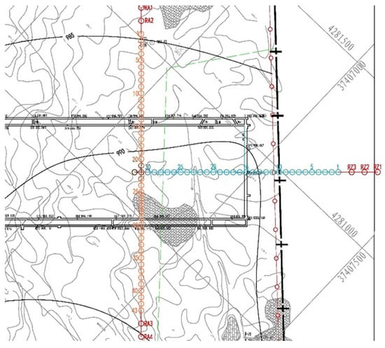
Figure 2.
Layout of surface rock movement observation.
4. Analysis of Surface Deformation Observation Data
4.1. Analysis of Observation Point Subsidence Data
For the inclination observation line A (Figure 3), when the working face advances about 259.8 m (the second observation), there was a small subsidence in the central observation point of line A, from which it can be inferred that line A began to settle from then on, but did not enter the subsidence active period. With the continuous advancement of the working face, the settlement and subsidence velocity of each observation point in line A gradually increased. It can be seen from Figure 3 that the relative subsidence value of the curve at the fourth observation was much larger than that at the third observation, which showed that line A had entered the active subsidence period. The maximum surface subsidence values at the fifth and seventh observations were 3.050 m and 3.302 m, respectively. The relative subsidence values between the two observations became smaller, indicating that line A had passed the subsidence active period and entered the subsidence recession period. The relative subsidence of the 13th observation curve was very small, indicating that the surface subsidence had gradually become gentle. In the last few measurements, the surface subsidence value was basically stable, and the maximum subsidence occurred at the A21 measuring point, reaching 3.350 m. The observation time interval for surface monitoring was designed based on the mining advance rate and subsidence. During the active subsidence stage, measurements were conducted every 10–15 days to capture rapid deformation. In the recession stage, intervals were extended to 30–60 days. The total monitoring period spanned 18 months, covering the complete subsidence cycle from initial face advance to post-mining stabilization.
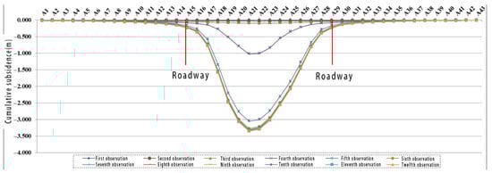
Figure 3.
Dynamic subsidence map of tendency observation line (line A).
It can be seen from the subsidence curve of the observation line Z in Figure 4 that the movement of each observation point was very small in the first comprehensive observation (advancing to 91.1 m). When the working face advanced about 151.6 m (between Z21 and Z22), namely the third observation, the observation points between Z16 and Z21 had obvious subsidence. Until the working face advanced to about 763.3 m (8th observation), Z16 basically reached the maximum subsidence value 0.661 m, which this time was in the Z16 subsidence active period. Through the analysis of data, it can be seen that, due to the influence of terrain and the advancement of the working face, the length of the subsidence active period of each measuring point in the Z line was different. When the local surface was stable, the maximum subsidence occurred at the measuring point Z19 (91.68 m from the tangent). The subsidence value was 4.173 m. It can be seen from the settlement curve of line Z (Figure 4) that the maximum subsidence development trend of goaf outside the observation area should be between 4.1 m and 4.2 m.
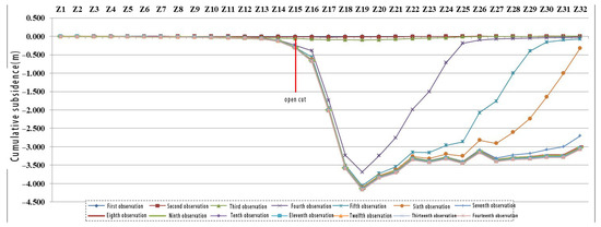
Figure 4.
Dynamic subsidence curve of strike observation line (Z line).
4.2. Analysis of Surface Movement Deformation Parameters
4.2.1. Inclination Variation Law
As shown in Figure 5, the variation regularity of inclination observation line A is obvious, and the inclination value near the trough is obviously larger, while the inclination values in the middle and both sides of the mining area are smaller. It can be seen from Figure 5 that, compared with the relative subsidence, the relative tilt change in each measurement was not so dramatic, and the maximum tilt occurs at A18~A19 to −37.595 mm/m.
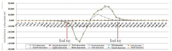
Figure 5.
Inclination observation line (line A) adjacent two points tilt value change chart.
As shown in Figure 6, the variation regularity of the strike observation line is weak, but the variation rule of the inclination value near the open cut was similar to the variation rule of the inclination observation line A in the basin, and the inclination value of the Z line was much larger than that of the A line. When the subsidence was stable, the maximum inclination of the Z line occurred at Z17–Z18 of −66.303 mm/m.
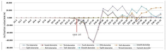
Figure 6.
Strike observation line (line A) adjacent two points tilt value change chart.
4.2.2. Analysis of Curvature Variation
As shown in Figure 7, the curvature variation regularity of inclination observation A was less regular due to the influence of coal seam mining height, topography, and burial depth. However, the overall analysis showed that the curvature value at the edge of the subsidence basin and 75 m away from the edge of the goaf were small, and the curvature value in the middle and edge of the goaf were large, in the range of 25~50 m.
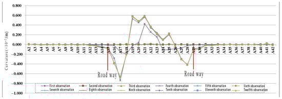
Figure 7.
Curvature map of measuring points on inclination observation line (line A).
As shown in Figure 8, the curvature value of each observation line fluctuated greatly, and the change rule is not obvious, which is related to the change in terrain.
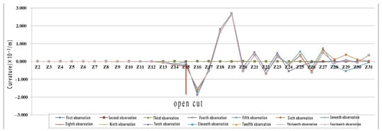
Figure 8.
Curvature map of observation points on strike observation line (Z line).
4.2.3. Analysis of Horizontal Movement Change
As shown in Figure 9, the surface horizontal movement values on both sides of the observation line, namely above the trough, are basically positive, indicating that the measuring points in the region continued to move to the middle of the goaf. The early values of the observation points located in the middle of the observation line were all positive. With the advancement of the working face, the horizontal movement value gradually became negative, indicating that the movement direction was opposite to the original direction. Since the surface subsidence of the central goaf was affected by the terrain, the moving direction had changed. When the settlement was stable, the maximum horizontal movement of line A occurred at point A19, reaching 481.752 mm.
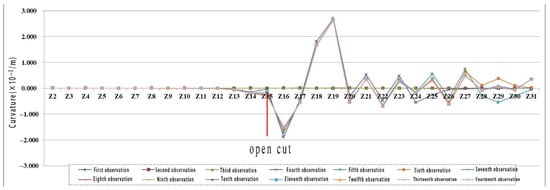
Figure 9.
Horizontal movement chart of observation points on the inclination observation line (line A).
As shown in Figure 10, the horizontal movement toward observation line Z is obviously different from that toward observation line A. The horizontal movement value of each observation point is relatively large. Affected by the advanced influence angle, each observation point reaches the maximum horizontal movement with the advance of the working face. To a certain extent, the horizontal movement and subsidence of each measuring point were corresponding. When the final settlement was stable, the maximum horizontal movement of the Z line occurred at Z16, and its value was 1038.542 mm.
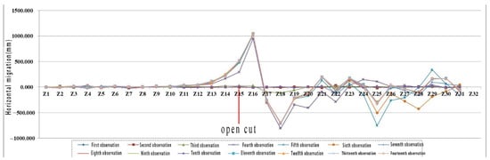
Figure 10.
Horizontal movement chart of each measuring point on the strike observation line (Z line).
4.2.4. Analysis of Subsidence Velocity Variation
The inclination observation line A is 390.6 m away from the tangent. As can be seen from Figure 11, during the second observation, some inclination points of line A gradually began to sink at a relatively low speed. With the advancement of the working face, the subsidence velocity also increases intermittently. When the active subsidence period was reached, there were two larger subsidence velocities. The maximum subsidence velocity was in the fifth observation A21, and the size was −126.732 mm/d. After the subsidence active period passed, the subsidence velocity of each point on the surface began to decrease gradually until the subsidence velocity tended to 0 when the surface was stable, and the subsidence basin had been formed at this time.
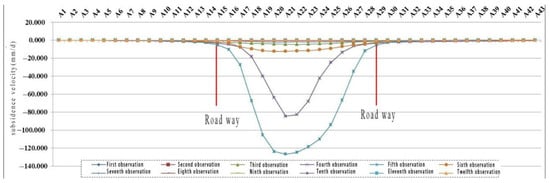
Figure 11.
Sinking velocity diagram of observation point of the inclination observation line (line A).
As shown in Figure 12, the time of the maximum subsidence velocity of each observation point in the strike observation line Z is inconsistent. With the advance of the working face, each observation point started to sink in turn, reached the maximum subsidence velocity in turn, and finally decreased gradually. In the fourth observation, the subsidence velocity of Z19 reached the maximum of −224.404 mm/d. It well reflected the actual law of surface subsidence: surface subsidence occurred suddenly, and the surface produced large subsidence in a very short time.
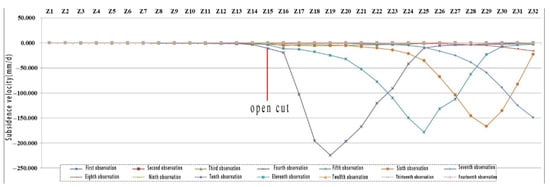
Figure 12.
Sinking velocity diagram of observation point of the strike observation line (line A).
On this basis, combined with the theoretical prediction formula in 2.1, the surface strata movement parameters are determined:
1 The boundary angles of comprehensive mining (the boundary angles of downhill, uphill, and strike direction are expressed as β0, γ0, δ0): δ0 = 52°, β0 = γ0 = 45°; integrated moving angles (moving angles of downhill, uphill, and strike direction are expressed as β, γ, and δ, respectively): δ = 80°, β = γ = 77°; comprehensive fracture angle (fracture angles in downhill, uphill, and strike directions are expressed as “″, ″″, and ″″): = 84°, = = 90°.
2 Full mining angles: ψ = 40.2°; advanced influence angle: ω = 70.2°; maximum subsidence velocity lag angle: Φ = 66.8°.
3 The probability integral method is used to predict the deformation of the main section of the surface moving basin during semi-infinite mining, and the prediction parameters suitable for the probability integral method are given: the average subsidence coefficient = 0.537; the main influence angle tangent tan = 4.435; horizontal movement coefficient b = 0.20; inflection offset = 76.90 m = 0.22 H; the propagation angle of mining influence θ = 86.2°. The measured surface subsidence curve is fitted by the theoretical prediction formula. The fitting results show that the parameters of the probability integral method determined by the measured data meet the requirements of the geological and mining conditions of the mining area, and the predicted results are in good agreement with the measured results.
4.2.5. Comparison with the Influence Function Method
The influence function method, a classical approach for predicting mining subsidence, was compared with our probability integral model results. While the influence function method efficiently estimates subsidence basins using empirical kernel functions, it often underestimates abrupt subsidence in high-intensity mining due to its assumption of continuous and gradual deformation. In contrast, our UDEC-based approach captures discontinuous rock mass behavior and staged subsidence development, showing better alignment with measured sudden settlement during the active stage (Figure 13). This comparison highlights the limitation of conventional influence function methods in western mining contexts and underscores the value of discontinuous numerical modeling for accurate subsidence prediction.
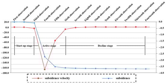
Figure 13.
Curve diagram of dynamic subsidence and subsidence velocity at Z21 point.
4.3. Analysis of Surface Movement and Deformation Characteristics
There was an obvious corresponding relationship between the subsidence velocity and the subsidence value of the surface Z21 observation point. Taking the measuring point Z21 as an example, the surface movement law was analyzed. It can be seen (Figure 13) that, when the advancing distance of the working face is short, the subsidence value and subsidence speed of the ground point are small, and it enters the starting stage of subsidence. When the subsidence value and subsidence speed increase rapidly during the continuous advance of the working face, the Z21 point reached the maximum subsidence speed, which was the active stage of subsidence. Subsequently, the subsidence velocity began to decrease, and the reduction process took a longer time than the increase process, mainly because, after the maximum subsidence velocity, the roof should be suspended for a certain length to reach the first weighting step, and the direct roof falls into the goaf. Because there was a process of gangue compaction in the goaf, it took longer to reduce the subsidence speed. With the continuous advancement of the working face, the final subsidence speed tends to be stable and close to zero.
Under the special mining conditions of Caojiatan mining area, the surface subsidence was not obvious from the initial stage to the active stage, and the surface subsidence occurred suddenly. The surface movement was intense in the active stage of subsidence, and most of the subsidence was achieved in a relatively short period of time.
5. Numerical Simulation of Surface Movement and Deformation
5.1. Numerical Simulation Approach and Software Justification
UDEC (Universal Distinct Element Code) was selected over continuum-based codes such as FLAC3D due to its explicit ability to simulate blocky, jointed rock masses undergoing large displacements and rotations. In the Caojiatan mining area, where the overburden contains distinct bedding planes and potential fracture networks, UDEC’s discrete element formulation allows for realistic modeling of caving, detachment, and void migration—processes that continuum models often simplify or neglect. This makes UDEC particularly suitable for analyzing vertical connectivity and sudden subsidence events observed in field monitoring.
5.2. Design and Establishment of Model
According to the drilling data of the 122,106 working face in the Caojiatan Coal Mine, referring to the rock composition and rock mechanics parameters in Table 1, the strike model of 1000 m long and 286 m high is established. As shown in Figure 14a, the variation law of strike rock displacement of working face is observed. The 2-2 coal seam was mined by the model, and a periodic weighting was excavated 12 times. Combined with the observation scheme of surface rock movement, a 50 m boundary coal pillar was set on the left side of the model. Referring to the rock composition and rock mechanics parameters in Table 4, the inclination model of 650 m long and 286 m high is established, as shown in Figure 14b, and the displacement law of inclined strata in working face is observed. The 2-2 coal seam is mined by the model, and the width of the first excavation face is 350 m. Combined with the field surface rock movement observation scheme, 150 m boundary coal pillars are set on the left and right sides of the model.
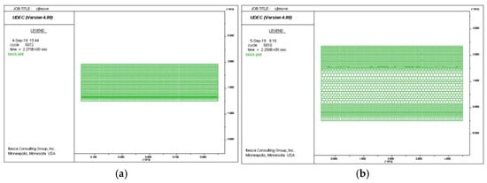
Figure 14.
Diagram of numerical simulation model for first mining face. (a) Schematic diagram of strike model of first mining face, (b) schematic diagram of incline model of first mining face.
Table 4.
Physical and mechanical parameters of coal and rock mass.
5.2.1. Model Boundary and Initial Conditions
The strike model (1000 m × 286 m) and dip model (650 m × 286 m) were discretized into deformable blocks with internal joints representing bedding planes and pre-existing fractures. Vertical boundaries were fixed in the horizontal direction, while the bottom boundary was fixed in both directions. The top surface was free to move under gravity. In situ stresses were initialized based on gravitational loading. Seepage condition: Neglected (western arid region, shallow groundwater level > 100 m, no significant seepage effect on subsidence).
5.2.2. Material Behavior and Stratified Modeling
The Mohr–Coulomb model was adopted for bedrock and coal (suitable for brittle fracture simulation) and the elastic–plastic model was adopted for loose layers (loess, red soil) considering plastic deformation. This was strictly based on drilling data (Table 4), with 12 layers (soil layer + 11 rock/coal layers) simulated. Each layer’s thickness, volumetric weight, and mechanical parameters are consistent with field tests (e.g., siltstone’s cohesive force = 8.6 MPa verified by triaxial shear tests). Pre-existing joints were added in the bedrock (dip angle 30–60°, spacing 5–10 m, aperture 0.1–0.5 mm) based on geological survey reports, using UDEC’s “joint element” to simulate joint shear slip.
5.2.3. Measuring Lines
The two models are set up with seven measuring lines. The working face is 7 m high. The measuring line A observes the displacement law of the direct roof, the measuring line B observes the displacement law of the basic roof, the measuring line C observes the displacement law of the key layer, the measuring line D observes the displacement law of the interface between the rock layer and the soil layer, the measuring line E observes the displacement law of the red soil layer, the measuring line F observes the displacement law of the loess layer, and the measuring line G observes the displacement law of the surface.
5.2.4. Model Limitations
The model assumes homogeneous material properties within each layer and does not account for small-scale heterogeneities or weathering effects. Groundwater flow and pore pressure changes are not considered, which may influence subsidence dynamics in saturated strata. Additionally, the model uses a simplified joint network based on bedding planes and does not explicitly incorporate pre-existing fractures, tectonic joints, or small-scale discontinuities that may influence local rock mass stability and subsidence patterns. This simplification may lead to an underestimation of surface fracture development and localized differential settlement.
5.3. Analysis of Simulation Results of Surface Movement and Deformation
5.3.1. Study on the Movement Law of Bedrock and Surface Along the Strike Direction (Z Line)
It can be seen from Table 5 that the first weighting immediate roof collapses obviously, the basic roof has subsidence, and the subsidence is not obvious. The rock stratum has no obvious subsidence. The maximum subsidence of measuring line A is 5.96 m, and the maximum subsidence occurs in the central position of goaf after mining. The direct roof caving part of the first periodic weighting is compacted, sinking 0.52 m compared with the first weighting. The basic roof has obvious subsidence, and the subsidence is 1.64 m. The interface between the key layer and the rock layer also has subsidence, and the subsidence is not obvious. Red soil, loess, and the surface have almost no subsidence. It shows that, in the first periodic weighting, the rock part has subsidence and the soil part has no obvious subsidence. The caving part of the direct roof under the second periodic weighting is further compacted, and the subsidence reaches 6.51 m, indicating that the subsidence of the direct roof is close to the mining height and is in a stable state under the second periodic weighting. The basic roof has obvious subsidence, and the subsidence is 4.28 m. The settlement of the critical layer has little change compared with the first cycle, indicating that the critical layer is not damaged. Red soil, loess, and the surface have almost no subsidence. The direct roof collapse part of the third cycle is in a stable state and is not sinking. The base top sinks further. Compared with the second periodic weighting, the subsidence of the key layer is significantly changed, and the subsidence is 4.44 m, which directly leads to the subsidence of the interface between the rock layer and the soil layer. In the fourth periodic weighting of the basic roof, the key layer shows further subsidence, and the most obvious is the rock and soil interface, soil, and surface subsidence. The maximum surface subsidence is 1.81 m, which is caused by the breaking of the key layer, resulting in the increase in soil subsidence above in the fifth periodic weighting base.
Table 5.
Overburden caving form and subsidence curve of observation line during excavation.
After the seventh periodic weighting, the surface subsidence reached the maximum value of 4.21 m. With the advancement of the working face, the surface subsidence continued to sink, and the maximum subsidence was 3.14 m, 3.63 m, 3.75 m, 3.86 m, 3.97 m, and 4.21 m, respectively, indicating that the surface subsidence tended to be stable after the seventh periodic weighting, and the maximum subsidence was 4.21 m. Then, with the advance of the working face, the surface subsidence range gradually expanded, and the surface movement area gradually reached the maximum subsidence, and finally remained stable.
It can be seen from Figure 15 that, when the working face is excavated to 800 m, the erosion rock damage basically reaches a stable state, and each survey line presents a subsidence basin form. The maximum subsidence value of line A is 6.75 m, the maximum subsidence value of line B is 6.15 m, the maximum subsidence value of line C is 5.75 m, and the maximum subsidence value of line G is 4.21 m. Therefore, after the mining stability, it can be seen that the surface subsidence tends to be stable after the seventh weighting, and the maximum subsidence is 4.21 m.
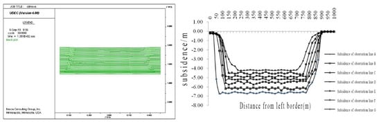
Figure 15.
Overburden caving form and subsidence curve of strike observation line at 800 m excavation.
The numerical simulation results show that the maximum surface subsidence value of the 122,106 working face after high-strength mining is 4.21 m, and the simulation value is close to the observation value of surface rock movement. The surface subsidence and subsidence area are about 2/3 of the direct top of the coal seam. It shows that, under the geological conditions, the vertical direction of mining rock has strong communication, and the subsidence of the direct roof will directly communicate with the surface, resulting in surface subsidence.
5.3.2. Study on Bedrock and Surface Movement in Tendency Direction (Line A)
It can be seen from Figure 16 that, when the working face is excavated at 800 m, the mining is stable, and the line A along the dip direction of the working face is basically in a stable state. The upper part of the whole goaf presents a subsidence basin, and the maximum surface subsidence reaches 3.34 m.
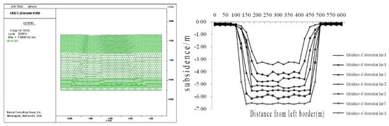
Figure 16.
Overburden caving form and subsidence curve of inclination observation line at 800 m excavation.
5.3.3. Analysis of the Influence Range of Surface Rock Movement
According to Figure 17, along the direction of the working face, the measuring points within 800~1000 m are located above the solid coal. It can be seen that the mining of the working face affects the surface above the solid coal in the range of 800~900 m, and the influence range is 100 m. It can be seen from Figure 18 that, along the inclination direction of the working face, the measuring points within 500~ 650 m are located above the solid coal. It can be seen that the influence range of the mining of the working face on the surface above the solid coal is 500~625 m, and the influence range is 125 m. It is concluded that the influence range of the working face excavation on the surface above solid coal is 100~125 m.
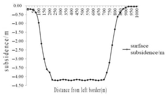
Figure 17.
Surface strike subsidence curve at 800 m excavation.
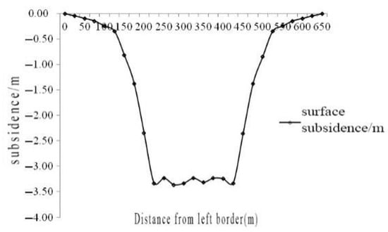
Figure 18.
Surface inclination subsidence curve at 800 m excavation.
5.4. Integration of Monitoring Data and Model Predictions for Practical Application
The UDEC model was calibrated using surface subsidence data from observation lines A and Z, ensuring that simulated displacement patterns matched field measurements in both magnitude and spatial distribution. This validated model can be used to achieve the following:
- (1)
- Predict subsidence for future panels under similar geological conditions;
- (2)
- Evaluate the effectiveness of mitigation measures such as backfilling, pillar design, or extraction sequencing;
- (3)
- Assess emergency scenarios including rapid subsidence events or structural failures;
- (4)
- Support land rehabilitation planning by estimating final ground topography and stability.
6. Discussion
The comparative analysis between the findings of this study and the established patterns from eastern Chinese mining regions reveals a fundamental geomechanical dichotomy by Liu et al. [29]. In contrast to the eastern mining areas characterized by thick unconsolidated layers and thin bedrock, where surface subsidence is typified by large magnitude, extensive influence range, and prolonged stabilization time, our study in the western Caojiatan mine demonstrates a distinct “sudden and intense” subsidence mode. This divergence is primarily governed by the geological structure: the thick, competent bedrock strata in the west facilitates a strong vertical connectivity of overburden failure, leading to rapid stress transfer and abrupt surface deformation, as evidenced by the high subsidence velocity (−224.4 mm/d) and the large main influence angle tangent (tanβ = 4.435). Consequently, monitoring and prevention technologies developed for the eastern context, which prioritize long-term, continuous deformation control, cannot be directly transferred. Their application in the west requires a paradigm shift towards high-temporal-resolution monitoring systems (e.g., real-time DAS, frequent UAV surveys) and prevention strategies focused on managing the sudden rupture of key strata, rather than mitigating slow, creep-like subsidence.
This research contributes to addressing the critical gap in quantitative characterization for western mining conditions. While studies in eastern regions, such as those in the southern Shandong coalfield, have successfully quantified the influence of the unconsolidated-to-bedrock thickness ratio on subsidence parameters, establishing critical thresholds (e.g., 1.25–1.75) for deformation behavior, a similar parametric framework for western, thick-bedrock settings has been lacking. Our work provides this essential baseline. The derived suite of parameters—including the subsidence coefficient (q = 0.537), inflection point offset (s = 0.22 H), and notably high tanβ—serves as a foundational dataset. These parameters not only quantitatively define the “Western characteristic” deformation pattern but also establish the necessary localized benchmarks. This enables the critical adaptation of prediction models (like the probability integral method) for western applications, moving beyond the inapplicable empirical parameters from the east and forming the theoretical basis for reliable hazard assessment and targeted control strategies in ecologically fragile western mining basins.
7. Conclusions
(1) In this study, the strike and inclination observation lines were designed and laid out for the 122,106 working face of the Caojiatan Coal Mine. Results showed that surface subsidence was mainly divided into three stages: initial stage, active stage, and recession stage. When the subsidence reached the limit, the surface subsidence was basically stable.
(2) Through the analysis of the observed data, the predicted parameters which were suitable for the application of the probability integral method were obtained: the average subsidence coefficient is 0.537. The main influence angle tangent tan = 4.435. The horizontal movement coefficient b = 0.20. The inflection point offset is 76.90 m. The propagation angle of mining influence θ = 86.2°.
(3) The discrete element numerical simulation software UDEC was used to simulate the surface movement law during coal seam mining. It is innovatively found that the rock formation has strong communication in the vertical direction. Meanwhile, the surface subsidence area accounted for 2/3 of the direct roof area of the coal seam. Moreover, the maximum subsidence value of the surface was 4.21 m and 3.36 m in strike and dip, respectively. The simulation results were basically consistent with the measured results of rock movement.
Author Contributions
W.Y.: Conceptualization, Writing—Original draft preparation, Writing—Review and editing, Supervision. Y.Z.: Conceptualization, Writing—Review and editing, Supervision and resources. Z.S.: Experimentation, Acquisition of data and interpretation of data. D.Z.: Methodology, Software, Visualization. K.P.: Validation, Writing—Review and editing. F.C.: Investigation, Data curation. All authors have read and agreed to the published version of the manuscript.
Funding
This research was financially supported by the National Key R&D Program of China (2023YFC3012102, 2021YFC2902004), the China National Natural Science Foundation (42027801, 42372297), New R&D Institution Construction Project of Ordos (IMRI23001), and the Fundamental Research Funds for the Central Universities (2023ZKPYSH01). The authors also thank the editor and reviewers for their constructive suggestions.
Data Availability Statement
The original contributions presented in this study are included in the article. Further inquiries can be directed to the corresponding author(s).
Conflicts of Interest
The authors declare no conflicts of interest.
References
- Qian, M.G. Efforts to be made to achieve the transition of Chinese coal industry from quantity to quality. China Coal 2017, 43, 5–9. [Google Scholar] [CrossRef]
- Yuan, J.H.; Zhang, K. Research and future forecast of coal power transformation in the middle and late period of the 13th five—Year plan. China Coal 2018, 45, 13–19. [Google Scholar] [CrossRef]
- Wang, X.L.; Ji, Z.G.; Xie, Y.T.; Yang, J.K.; Wu, P.; Wang, X.; Guo, X.Q. Present situation and development trend of gas emission prediction technology in coal face. Sci. Technol. Eng. 2019, 19, 1–9. [Google Scholar] [CrossRef]
- Zhao, D.; Zeng, Y.; Sun, X. Rock Damage and Aquifer Property Estimation from Water Level Fluctuations in Wells Induced by Seismic Waves: A Case Study in X10 Well, Xinjiang, China. Shock. Vib. 2021, 2021, 2137978. [Google Scholar] [CrossRef]
- Yang, S.L.; Wang, Z.H.; Jiang, W.; Yang, J.H. Advancing rate effect on rock and coal failure format in high—Intensity mining face. J. China Coal Soc. 2016, 41, 586–594. [Google Scholar] [CrossRef]
- Yang, D.M.; Guo, W.B.; Tan, Y.; Wang, Y.; Ma, X.; Li, Z. Lithology and fissure characteristics of overburden in high—Intensity mining. J. China Coal Soc. 2019, 44, 786–795. [Google Scholar] [CrossRef]
- Fan, L.M.; Xiang, M.X.; Peng, J.; Li, C.; Li, Y.H.; Wu, B.Y.; Bian, H.Y.; Gao, S.; Qiao, X.Y. Groundwater response to intensive mining in ecologically fragile area. J. China Coal Soc. 2016, 41, 2672–2678. [Google Scholar] [CrossRef]
- Zhao, D.; Zeng, Y.; Wu, Q. Source Discrimination of Mine Gushing Water Using Self—Organizing Feature Maps: A Case Study in Ningtiaota Coal Mine, Shaanxi, China. Sustainability 2022, 14, 6551. [Google Scholar] [CrossRef]
- Liu, S.J.; Li, T.; Ma, H.T.; Liu, S.P. Study on the Ground Subsiding Area Caused by Underground Mining and Its Developing Tendency. Met. Mine 2015, 44, 152–156. [Google Scholar] [CrossRef]
- Zhao, D.; Wu, Q.; Zheng, G. Quantitative Source Apportionment and Uncertainty Analysis of Heavy Metal (loid) s in the Topsoil of the Nansi Lake Nature Reserve. Sustainability 2022, 14, 6679. [Google Scholar] [CrossRef]
- Li, Y.; Wang, Z.; Zhang, L. Analysis of surface collapse and geofracture caused by steep coal mining in loess hilly region: Taking the surface collapse in a community in Huating County, Gansu Province as an example. J. Geotech. Eng. Environ. Prot. 2025, 9, 45–52. [Google Scholar] [CrossRef]
- Ordos Zhuolongwan Coal Co., Ltd. Tendering Announcement for 35kV Linta Line Collapse Treatment in Goaf Areas. China Sunshine Procurement Service Platform. 2025. Available online: http://www.ygcgfw.com/gggs/001001/001001001/20250126/8a81809a94936da90194a0e0d62b3592.html (accessed on 15 March 2025).
- Tang, F.; Yang, Q. Progress and prospects of multi-source remote sensing monitoring technology for coal mining subsidence in mining areas of the western Loess Plateau. Coal Sci. Technol. 2023, 51, 9–26. [Google Scholar] [CrossRef]
- Anke Technology. GNSS Automated Monitoring System for Open-Pit Mine Slopes and Goafs. NetEase News. 26 March 2023. Available online: https://c.m.163.com/news/a/I0P4C9IL0553SWI6.html (accessed on 26 March 2023).
- Chen, W.; Li, C.; Zhao, Y. GNSS displacement monitoring stations: Application and efficiency in coal mine goaf safety. NetEase News 2025, 25, 1–9. Available online: https://c.m.163.com/news/a/K8C4LFCL0556FJTQ.html (accessed on 6 June 2025).
- Liu, J.; Zhang, Y.; Wang, H. UAV + AI Recognition Technology for Surface Collapse and Fissure Monitoring in Coal Mines. China Coal News. 2024. Available online: https://www.mtkxjs.com.cn/cn/article/doi/10.12438/cst.2023-0438 (accessed on 8 July 2024).
- Hasan, M.; Su, L.; Cui, P.; Shang, Y. Development of deep-underground engineering structures via 2D and 3D RQD prediction using non-invasive CSAMT. Sci. Rep. 2025, 15, 18. [Google Scholar] [CrossRef]
- Hambleton, J.P. Geomechanics of subsidence above single and multi—Seam coal mining. J. Rock Mech. Geotech. Eng. 2016, 8, 189–200. [Google Scholar]
- Zhang, Y.P.; Yang, S.Y.; Lu, Z.G.; Su, X.P.; Xia, G.J. 3D Visualization Processing and Analysis of Surface Subsidence Rule of a Mined—Out Area. Met. Mine 2013, 42, 120–123. [Google Scholar] [CrossRef]
- Visser, A.T.; du Plessis, J.A. Numerical analysis of surface movement due to multi—Seam mining in soft rock formations. J. Rock Mech. Geotech. Eng. 2018, 10, 765–774. [Google Scholar]
- Karpuz, C.; Ayhan, S. Field measurements and numerical modeling of surface subsidence in a coal mine with complex geology. Environ. Earth Sci. 2020, 79, 456. [Google Scholar]
- Yu, X.Y.; Wang, P.; Li, X.L. Analysis on characteristics of surface subsidence with Han Jia Wan coal mine. Adv. Mater. Res. 2012, 524, 520–524. [Google Scholar] [CrossRef]
- Xiong, Z.Q.; Jun, H.; Zhao, L.L. Study on the Regularity of Surface Movement and Deformation in Long Coal Face with Large Mining Height. Adv. Mater. Res. 2012, 594, 86–91. [Google Scholar] [CrossRef]
- Guo, Q.; Guo, G.; Lv, X.; Zhang, W.; Lin, Y.; Qin, S. Strata movement and surface subsidence prediction model of dense solid backfilling mining. Environ. Earth Sci. 2016, 75, 1426. [Google Scholar] [CrossRef]
- Dudek, M.; Mrocheń, D.; Sroka, A. Integrating the finite element method with python scripting to assess mining impacts on surface deformations. J. Appl. Sci. 2024, 14, 7797. [Google Scholar] [CrossRef]
- Li, H.; Zha, J.; Guo, G. A new dynamic prediction method for surface subsidence based on numerical model parameter sensitivity. J. Clean. Prod. 2019, 233, 1418–1424. [Google Scholar] [CrossRef]
- Zhang, S.L. Study of Surface Subsidence Prediction Optimization Based on Practical Data. Coal Min. Technol. 2017, 22, 5. [Google Scholar] [CrossRef]
- NB/T 11553-2024; Technical Specification for Observation of Surface Movement and Deformation in Coal Mines. China Standards Press: Beijing, China, 2024.
- Liu, H.; Li, Y.; Su, L.; Zhu, X.; Zhang, P.; Yao, M.; Wang, J.; Wang, Q.; Si, G. Surface Deformation Law in Mining under Thick Loose Layer and Thin Bedrock: A Case Study of Lunan Mining Area. Coal Sci. Technol. 2023, 51, 11–23. [Google Scholar] [CrossRef]


Disclaimer/Publisher’s Note: The statements, opinions and data contained in all publications are solely those of the individual author(s) and contributor(s) and not of MDPI and/or the editor(s). MDPI and/or the editor(s) disclaim responsibility for any injury to people or property resulting from any ideas, methods, instructions or products referred to in the content. |
© 2025 by the authors. Licensee MDPI, Basel, Switzerland. This article is an open access article distributed under the terms and conditions of the Creative Commons Attribution (CC BY) license.