Abstract
The damage assessment of structures subjected to confined internal blast remains a focal point in the field of explosion. However, current research results are mostly limited to the situation where the cabin structure dimensions remain constant, and the influence of cabin structure dimensions on damage effect under internal blast has not been systematically considered. In order to study the influence of structural dimensions on deformation and deflection of plate under confined blast loadings, LS-DYNA R11.1 finite element simulation software was used, based on a fluid–structure interaction (FSI) algorithm, to carry out simulation research on blast under different cabin structure parameters. The propagation law of blast shock waves under different cabin structure parameters was analyzed, and the deformation and deflection of the plate at the end of the cabin under different explosion equivalent and explosion point positions were studied. The results indicate that when the mass of the explosive remains constant, the location of the explosion point and the structural parameters of the cabin are the main factors affecting the deformation and deflection of the plate. When the distance between the explosion point and the proximal plate is the same and the aspect ratio is 2, the deflection of the proximal plate is smaller than that of the distal plate. When the aspect ratio is 3, as the distance between the explosion point and the proximal plate increases, the deflection of the proximal plate gradually increases, while the deflection of the distal plate first decreases and then increases. When the aspect ratio is 4, 5, and 6, as the distance between the explosion point and the proximal plate increases, the deflection of the proximal plate first increases and then decreases, and the deflection of the distal target plate first decreases and then increases. The research results can provide some reference for the damage assessment of internal blast in structures and the design of structural protection.
1. Introduction
The ship cabin is considered as a relatively confined system, the shock wave load generated by the blast in the cabin constantly propagates and reflects in the confined space, with a more complex propagation law than in air. In recent years, the damage effect of internal blast loads on the end target plate has become one of the key research objects. Zhang et al. [1] pointed out that there is still insufficient understanding of the conditions and mechanisms for the plastic deformation of plates under internal blast. Ren et al. [2,3] studied the saturation pulse phenomenon of a fully clamped rectangular plate under an internal blast loading, deduced the relationship between saturation duration and saturation deflection, and studied the dynamic response of a scaled chamber under an internal blast loadings through experiments and simulations, with similar deformation trends. Olson et al. [4] investigated the failure mode of a clamped square mild steel plate under uniformly distributed blast pressure loading. Zhao et al. [5] studied the response law of stiffened plate under confined blast loads and found that the ultimate deflection of outer-stiffened plate was smaller than that of the inner-stiffened plate. Wang et al. [6] studied the overpressure changes and damage characteristics of double cabin structures under different blast loadings. Cheng et al. [7,8,9] compared the effects of different fluid media on the blast load transfer and structural damage mechanism of multi-chamber structures, and then studied the coupling damage effect of two charges exploding simultaneously underwater on multi-cabin structures. The study showed that the coupling of shock wave and bubble in the central region would exacerbate the structural damage. A single explosion can cause more damage than multiple explosions. Longère et al. [10] used numerical simulation technology to study the dynamic damage forms of ship structural steel caused by near-field air shock wave under different explosive mass and different explosion distance. Zhang et al. [11] compared the inelastic deformation performance of steel plate and polyurea-steel laminate plates under confined blast loadings. The study showed that, using the maximum central deflection as the criterion, the monolithic steel plate was better than the equal mass polyurea-steel laminate. Li et al. [12] proposed an ultralight all-metallic honeycomb sandwich panel in order to reduce the damage degree of ships under internal blast loadings. Compared with single-layer metal plates of the same quality, it can effectively enhance blast resistance. The conclusion shows that the sandwich plate primarily dissipates impact energy through the overall out-of-plane bending, in-plane stretching, and local internal core breaking. Jiba et al. [13] studied the effect of water mist environment in semi-confined blast chamber on parameters such as shock wave. They found that, compared with atmospheric conditions, both in number and in amplitude of pressure reflection were significantly decreased, resulting in a lower pulse under a water mist environment. Wang et al. [14] explored the characteristics of the first incident shock wave and quasi-static pressure under internal blast. In the case of the same mass and benchmark explosive, the pressure loads generated by internal explosion of ideal explosive and aluminum-containing explosive is similar. Chen et al. [15] divided the cabin explosion space into non-corner central zone, near-wall zone, two-sided corner zone and three-sided corner zone, and obtained an engineering model for calculating shock wave load in different zones by using numerical simulation methods. Li et al. [16] found that the high pressure area formed under the internal blast loadings had a significant impact on the damage of the bulkhead structure, and came up with the reasons for the formation of corner high pressure in different cabin structures. Li et al. [17] studied the dynamic response of the stiffened plate under internal blast loads, and analyzed the effects of shock wave characteristics, support spacing, and stiffened position on the deflection and failure mode of the stiffened plate. Qin et al. [18] proposed a theory of the best approximation method to modify the thickness scale factor in order to improve the dynamic response of the structure of the scale model when the material is different from the prototype, and verified the reliability of the method through experiments.
Li et al. [19] studied the blast resistance of the liquid cabin. Their study summarized the typical deformation mode of the liquid cabin plate and analyzed the pressure characteristics, deformation mechanism of the front, and rear plates, and energy changes of the cabin. Geretto et al. [20] studied the influence of different constraints and different plate thicknesses on the deformation of plates. Under the premise of the same explosive mass, the midpoint deflection would increase with the increase in constraint degree. Yao et al. [21] studied the dynamic response of a steel cabin under internal blast, and found an effective method to simulate the dynamic response of a structure under blast. Zheng et al. [22] studied the deflection deformation of stiffened plates under internal blast loads. They observed distinct yield lines around the clamped edges and diagonal lines of the plates. The dynamic response and permanent displacement of the components were calculated using classical steel–plastic and elastoplastic methods. Yuan et al. [23,24] studied the effect of standoff distance on saturation deflection and saturation impulse of a fully clamped square target plate under internal blast loading. Li et al. [25] investigated how the deformation and failure modes of a square plate with fixed boundaries vary as a function of standoff distance. Yao et al. [26,27] analyzed the deformation of a cabin under internal blast loading. They proposed a dimensionless number to predict the structural dynamic response and documented the typical failure modes of the side plates for different explosive sizes and masses. Furthermore, they elucidated the failure process and mechanism for each mode. Carney et al. [28] combined experimental and numerical methods to study the response of aluminium circular plates under internal blast loading, and determined the distance and charge mass required to generate initial cracks in aluminium plates. Zhao et al. [29] demonstrated through scaling experiments that the results of appropriate scaling of the structure satisfy the similarity law. Kong et al. [30] demonstrated through dimensional analysis that the blast loads under internal blast satisfies the similarity criterion, while the target plate response does not meet the similarity criterion. Bai et al. [31] studied the phenomenon for rectangular pulse loading on a rectangular plate under various symmetric boundary conditions and found that the saturated duration and saturated pulse were only determined by the deformation mechanism. Dragos et al. [32] proposed and verified a method to simplify highly irregular explosion loads under full confinement. Salvado et al. [33] proposed a new method for calculating adjacent cabin peak overpressure based on empirical formulas and numerical simulation methods. Zhou et al. [34,35] established the relationship between the deformation deflection of the plate in a confined space and the energy released by explosives.
Previous research on the structural response to internal blasts was conducted with cabin structural parameters held constant. The research on the influence of different cabin structural parameters on the deformation deflection of the plates and blast loadings distribution under internal blast loadings is limited. This paper aims to conduct numerical simulations on the response of a fully clamped square steel plate subjected to internal explosion loads. The objective is to gain a deeper understanding of shock wave propagation within explosion chambers of varying lengths and their interaction with different target plates, thereby addressing the limitations identified in previous research. The loads are generated by detonating cylindrical TNT charges at various distances from the plate within the blast chamber. Finite element analysis will be employed to investigate the damage effects of different cabin geometries and blast distances on the end target plate under internal blast loads. The limitations of the current findings will be critically reviewed, highlighting the importance of geometric constraints in internal explosion-proof design.
2. Finite Element Modeling
2.1. Geometric Model
To investigate the effect of cabin structural dimensions on the deformation and deflection of the plates under internal blast loadings, a model of a blast loading device was developed based on Reference to [23], as shown in Figure 1. The model consists of a blast chamber, plates, and flanges, all made of Q235 steel. The three components are assembled using 32 × 18 mm bolts. Two identical plates are fixed to the end of the cabin and clamped using flanges to achieve the constraint effect on the plates. Stiffeners are equidistantly arranged on the outer surface of the blast chamber. The geometric dimensions of the device are shown in Figure 2. The overall width (W) and overall height (T) of the structure are fixed values, both of which are 600 mm. The overall length (L) of the chamber is a variable in this article, as detailed in Section 3.2. The aspect ratio of the blast chamber is defined as γ, i.e., γ = L/W. The central opening of the flange is a square area with a side length h = 500 mm, and the opening dimensions of the blast chamber is consistent with the flange. The thickness of the blast chamber, flange, and stiffeners is 8 mm. The thickness of the plate is 1 mm. The explosive is a cylindrical charge located inside the blast chamber, with the Y direction on the center plane of the blast chamber and equal distance from the upper and lower walls. The position in the X direction is determined by R1 and R2, R1 + R2 = L, as shown in Figure 3. R1 and R2 are defined as the proximal and distal blast standoff distances, respectively.
Figure 1.
Schematic diagram of the structure of the chamber.
Figure 2.
Schematic diagram of the geometric model of the chamber.
Figure 3.
Explosive position diagram.
2.2. Finite Element Model Setup
Commercial software ANSYS/LS-DYNA R11.1 was used for finite element modeling and calculation. The Arbitrary Lagrange–Euler (ALE) method is used to capture the interaction between fluid and structure, and the penalty coupling technique is used to strengthen the interaction between fluid and structure. In this paper, the numerical simulation does not consider the combustion effect after explosive explosion. Although the afterburning effect can enhance the damage effect, it can be almost ignored by comparing the results of simulation and test.
Since the blast loading device has a geometrically symmetric structure, a 1/4 finite element model can be established, and symmetric boundary conditions are used to constrain it. As shown in Figure 4, the model consists of air, explosive, explosive chamber, flange, plate, and bolts. The Euler algorithm is used for air and explosives, and Lagrange algorithm is used for explosive chamber, flange, plate, and bolts. All structure components were modeled using eight-noded hexahedral elements (SOLID 164). Considering that the blast chamber wall and bolts undergo negligible deformation in the experiment and are designed for repeated use, they are modeled as rigid bodies, with their deformation ignored.
Figure 4.
Finite element model of the blast chamber (taking γ = 3 as an example).
In finite element simulation calculations, grid convergence analysis is a key step in ensuring the reliability and accuracy of the calculation results. Therefore, the grid dimensions of the plate are divided into 2 mm, 4 mm, 6 mm, and 8 mm, and the air grid dimensions are twice the grid dimensions of the plate. The reason is that the grid dimensions of the plate are smaller than those of the air domain to avoid material leakage, which is caused by the software itself. The variation of deflection of the plate under different grid dimensions is shown in Figure 5. From the figure, it can be seen that as the grid changes from 8 mm to 2 mm, the deformation deflection of the proximal target plate gradually approaches the experimental value, with 2 mm and 4 mm being basically the same. For the distal plate, 6 mm and 8 mm are smaller than the experimental value, while 2 mm and 4 mm are larger than the experimental value, and the error of 2 mm is greater than 4 mm. Taking into account the deformation deflection of the plate under different grid sizes, while considering the calculation accuracy and time efficiency, the plate size of 4 mm and the air grid dimensions of 8 mm are selected. The grid dimensions of bolts, flanges, and the blast chamber are consistent with the plate. Due to the varying geometry of the explosive chamber, the total number of solid and fluid elements increases with the aspect ratio γ: 598,110 for γ = 3; 772,955 for γ = 4; 946,639 for γ = 5; and 1,120,323 for γ = 6.

Figure 5.
Schematic diagram of deflection changes of plates with different grid dimensions.
A total of 624 observation points are set near each plate, a total of 1248 observation points, which can accurately capture the general characteristics of the internal blast loadings generated after explosion.
2.3. Material Model
The explosive material model uses MAT-HIGH_EXPLOSIVE_BURN, and the equation of state uses Jones–Wilkins–Lee (JWL), which describes the adiabatic expansion of the detonation products. Pressure is expressed as a function of volume v and energy e, as shown in Equation (1):
where , , and ω are dimensionless terms; and are pressure terms. The explosion parameters include initial density of explosive , Chapman–Jouguet pressure and detonation velocity D. The specific parameters are shown in Table 1.

Table 1.
Material model and state equation parameters of explosives.
The explosive is surrounded by air. The air Euler domain sets an outflow boundary to allow the gas products to dissipate outside the boundary of the air Euler domain. The Euler region is greater than the cabin length L to account for its deformation. Air is an ideal gas and its equation of state is as follows:
where is the specific heat ratio, is the air density, is the internal energy, and is the initial air pressure. The specific parameters are shown in Table 2.
Table 2.
Material model and equation of state parameters for air.
The Johnson–Cook (JC) material model captures the effects of strain hardening, temperature softening and rate dependence on the ductile material, and is used to describe the constitutive behavior of the target plate. In the JC material model, Von Mises equivalent flow stress σ is associated with equivalent plastic strain ε, strain rate , and temperature T in the following expressions:
where is the dimensionless plastic strain rate, is the corresponding temperature, A is the static yield stress, B is the strain hardening coefficient, n is the strain hardening index, C is the strain rate sensitivity coefficient, m is the thermal sensitivity index, is the reference strain rate. is the reference temperature, and is the melt temperature. The terms in the first and second brackets of Equation (3) correspond to the strain hardening and strain rate dependence of the material model at room temperature, respectively. The specific parameters are shown in Table 3.
Table 3.
Material model parameters of Q235 steel.
2.4. Model Verification
Following the experimental setup in reference [23] (Figure 6a), a 1:1 finite element model was developed, as shown in Figure 6b. The cabin length is 1000 mm. The proximal and distal blast standoff distances and , were set to 125 mm and 875 mm, respectively. Three different charge amounts are compared, which are 50 g, 75 g, and 100 g respectively. The material model and equation of state used in the simulation are shown in Section 2.3. The experimental results and simulation results are shown in Table 4. It can be seen that the error of both numerical calculation and experimental results is less than 15%, which proves the reliability of the simulation model. Figure 7 shows the comparison between simulation and test results of the end target plate when the explosive is 50 g and R1 = R2 = 500 mm, which can capture the deformation of the target plate.
Figure 6.
Model of the explosion chamber: (a) experimental model [23]; (b) simulation model.
Table 4.
Comparison table between simulation results and test results [23].
Figure 7.
Comparison results between simulation and experiment when the explosive is 50 g and R1 = R2 = 500 mm: (a) front view; (b) side view.
3. Results
Yuan et al. [23] showed that when the length of the blast chamber is 1000 mm, the permanent central displacement of the proximal plate () is smaller than that of the distal plate () at different explosion distances and equivalents. According to the results of the study, this phenomenon is not related to the amount of charge, but only to the location of the charge. Because the length of the cabin is too large, the propagation distance of the shock wave in the simulation process is too far, resulting in energy attenuation and ultimately inaccurate results. Therefore, four types of cabins with the aspect ratio from 3 to 6 were selected. In order to exclude the influence of the charge, 75 g and 100 g amounts were used. Each set of simulation was loaded with two target plates.
3.1. Calculation Result
A total of 44 simulations were carried out by changing the blast distance and equivalent under different blast chamber lengths. The detailed results are shown in Table 5, and all plates exhibit large inelastic deformations.
Table 5.
Simulation results of cabin with different aspect ratios.
Visualization of Table 5, as shown in Figure 8, can better see the influence of different explosion positions on the permanent center displacement of the plate under different explosion chamber lengths. When the explosive is located in the central position, the deformation of the target plates at both ends is almost the same, which is consistent with the expectation. When γ = 3 and R1 ≤ 750 mm, increases nearly with the increase in R1, while decreases first and then increases with the decrease in R2. For γ ∈ [4, 6], firstly increases and then decreases with the increase in R1, with the turning point at R1 = 750 mm. In contrast, decreases first and then increases with the decrease in R2.
Figure 8.
The permanent center displacement results of the lower end of the target plate at different detonation distances when γ = 3~6.
From R1 = 125 mm, to 375 mm, and then to 500 mm, the proximal plate monotonously increases and the distal plate monotonically decreases, which is consistent with the research results of Yuan et al. [23] However, the phenomenon that the proximal plate is smaller than the distal plate changes with the increase in L. When 500 mm ≤ R1 < L/2, the proximal plate is larger than the distal plate. The above results are mainly due to the different mechanism of pressure wave reflection on the two ends of the target plate in the closed chamber. The reasons for this are explained in detail in Section 3.2.
3.2. Explanation
As shown in Figure 8, when L = 1500 mm, R1 = 750 mm is the central position, but its change law is the same as that of γ ∈ [4, 6], R1 ≤ 750 mm. Therefore, the laws presented by γ = 3 and γ ∈ [4, 6] are unified, that is, when R1 ≤ 750 mm, presents a trend of first increasing and then decreasing with the increase in R1. Since the variation trend is consistent, γ = 5, R1 = 500 mm, 750 mm, and 1000 mm will be selected to explain the above rules.
Under the three working conditions, the displacement curves, interface overpressure, and impulse curves of the plates at both ends are shown in Figure 9. In each figure, the changes in the permanent center displacement w of the plate, average interface overpressure PInt(t) and accumulated impulse I per unit area over time are plotted. In order to study the damage effect of the blast load on the end target plate more pertinently and save the calculation time, the explosion time of the numerical model is set at 9 ms. Average interface overpressure PInt(t) is defined as the average overpressure acting on the interface between an air domain and a structure. Cumulative impulse per unit area is the integral of overpressure and time, i.e., I(t) = [22]. The variation trend of the internal pressure is basically the same, that is, it first rises to the maximum peak, then decreases sharply and maintains a quasi-static pressure for a period of time. Due to the constraint effect of confined space, the blast loads are constantly reflected in the confined space, resulting in the plate experiencing a smaller secondary peak. The plates at both ends are still in a slight fluctuation state after reaching the maximum permanent center displacement, which is an inevitable phenomenon. This occurs because the positive overpressure will continue for a certain time after the explosion inside the cabin, resulting in a rebound of the target plate. However, not all the impulses generated by overpressure contribute to the center displacement deflection of the target plate. The impulse corresponding to the maximum w is called the saturation impulse of the target plate, that is, the impulse corresponding to the moment in Figure 9. After the tw moment, the impulse continues to increase, but does not contribute to the w of the target plate. In order to better explain the above phenomenon, the corresponding pressure contour map calculated by the finite element method is supplemented in Figure 10, Figure 11 and Figure 12.

Figure 9.
Schematic diagram of displacement, interface overpressure, and impulse curves of target plates at both ends under three conditions of 75 g charge: (a) proximal plate; (b) remote plate.
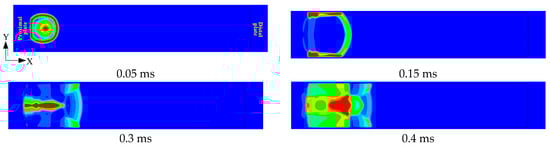
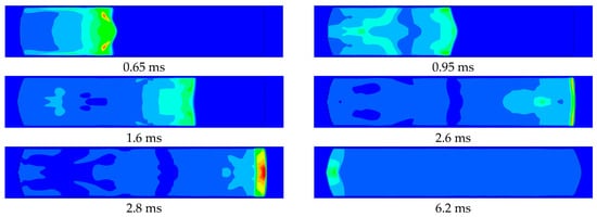
Figure 10.
Diagram of implosion load propagation at γ = 5, R1 = 125 mm, and R2 = 2375 mm.
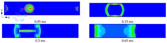
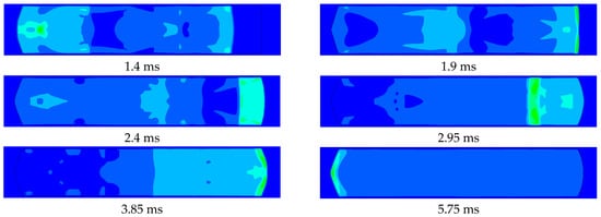
Figure 11.
Diagram of implosion load propagation at γ = 5, R1 = 750 mm, and R2 = 1750 mm.
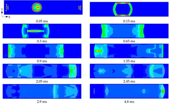
Figure 12.
Diagram of implosion load propagation at γ = 5, R1 = 1000 m, and R2 = 1500 mm.
Figure 9 indicates that for R1 = 125 mm, the pressure (P) on the proximal plate is significantly higher than on the distal plate. This is because the charge is closer to the proximal target plate, and the shock wave will attenuate with the increase in distance in the propagation process. Furthermore, Figure 10 reveals that the duration of the explosive load acting on the proximal target plate is very brief. After the spherical shock wave acts on the proximal target plate, it quickly converges in the corner and propagates along the wall. The resulting reflected wave subsequently converges at the center and then rapidly propagates to both sides. Since the shock wave will accelerate its propagation speed in the air disturbed by the shock wave, it overlaps with the other end of the shock wave at 1.6 ms and acts on the distal target plate together.
As a result of the superposition of shock waves, the profile of the shock wave front acting on the distal target plate evolves from convex to concave. The shock wave near the upper and lower walls makes first contact, and the resulting reflected waves converge near the distal plate. Although the peak overpressure of the proximal target plate is significantly higher than that of the distal target plate, this convergence phenomenon prolongs the duration of positive pressure. This results in a larger saturation impulse on the distal plate than on the proximal one. Therefore, the displacement of proximal target plate is smaller than that of the distal target plate. The reflected shock wave generated by the distal target plate acts on the proximal plate, generating a secondary peak. The chamber’s confinement causes the shock wave to be continually reflected and superimposed. Despite the attenuation in peak pressure, both the proximal and distal plates experience multiple loadings. The scenarios with R1 = 750 mm and R1 = 1000 mm exhibit comparable responses. Since the target plate had already reached its saturation displacement before the secondary peak arrived, this subsequent pressure loading does not contribute to further permanent deformation.
The propagation process of shock wave at R1 = 750 mm is shown in Figure 11. The initial shock wave contacts the upper and lower walls at 0.15 ms, prior to reaching the proximal plate. The resulting reflected waves subsequently converge at the center by 0.3 ms. The resulting reflected shock wave after convergence interacts with the initial shock wave and propagates toward both ends. The shock waves impinge on both target plates in the form of plane waves. However, the increase in R1 results in a decrease in the peak pressure of shock wave at the proximal target plate. Due to the increase in the propagation distance, the reflected wave from the proximal target plate cannot catch up with the other end of the shock wave, causing its peak value to decrease. The reflected shock wave from the proximal end meets the one from the distal end near the distal target plate, and then the shock wave continues to propagate to both sides, resulting in a secondary peak. The proximal target plate experiences a higher peak pressure, which generates a larger impulse and thus a greater deflection than the distal plate. Compared with the findings in Reference [23], the cabin geometry significantly influences the damage effect of the end target plate.
For the proximal plate, although the peak overpressure is higher at R1 = 125 mm, the positive phase duration is shorter. Consequently, both the impulse and the plate deflection are smaller than those at R1 = 750 mm. In contrast, for the distal plate, both the peak overpressure and duration are greater at R1 = 125 mm, leading to a larger impulse and thus greater deflection. Therefore, the damage effect of the end target plate is not only related to the peak value of overpressure, but also to the positive pressure duration. The increase in standoff distance R1 moderates the overpressure attenuation. This occurs due to a sequence of shock wave interactions. The shock wave converges at the central position at 0.3 ms and propagates toward the proximal end. The reflected wave generated by the initial shock at the proximal plate then interacts with this converging wavefront near the plate, thereby slowing the decay of the local overpressure.
When R1 increases from 750 mm to 1000 mm, the peak overpressure of the proximal target plate decreases, while the peak overpressure of the distal target plate increases. The decisive factor governing this phenomenon is the propagation distance of the shock wave load. Therefore, the deflections of the proximal target plate decrease, whereas those of the distal plate increase. As shown in Figure 11, the interaction time between the reflected shock waves from both target plates increases with R1. Furthermore, their convergence point shifts closer to the chamber’s center.
4. Discussion
This study demonstrates that the geometric dimensions of the blast chamber significantly influence the damage effect of the end target plate and the distribution of the blast loading inside the chamber. The relative magnitude of the permanent plastic displacement between the proximal and distal plates is not constant. It depends on the chamber’s aspect ratio (γ) and the explosive location (R1 and R2). There exists a critical location for the explosive, beyond which this relationship reverses. The propagation distance of shock waves is also a crucial factor. The findings of this study are based on a fixed cabin cross-sectional area. Future work is needed to examine their applicability to designs with different cross-sectional areas but the same aspect ratio.
5. Conclusions
Through finite element analysis, this study systematically investigates how different cabin dimensions and explosive placement affect the deflection of plates. Furthermore, it also analyzes the propagation characteristics of blast loads within confined spaces. The main conclusions are summarized as follows:
(1) The deflection of target plates under internal blast loading is determined by the peak overpressure and the positive pressure duration.
(2) For R1 ≤ 750 mm, the deflection of the proximal plate increases with increasing explosion distance. However, the deflection decreases for R1 > 750 mm. This decreasing trend is consistent with the general conclusion in air.
(3) When the aspect ratio of the blast chamber is γ ∈ [3, 6], there is a critical position Rn (125 mm < Rn < 500 mm). When R1 ≤ Rn, the deflection of the proximal plate is smaller than that of the distal plate. When Rn ≤ R1 ≤ L/2, the deflection of the proximal plate is larger than that of the distal plate.
(4) When the aspect ratio of the blast chamber is γ ∈ [3, 6] and R1 ≤ 125 mm, the reflected shock wave from the proximal target plate interacts with the initial shock wave propagating toward the distal plate. This superposition prolongs the positive pressure action time at the remote target plate, resulting in a greater impulse. Consequently, the displacement at the proximal plate is smaller than the distal plate.
The research results can provide certain data and references for the internal blast damage assessment of structures, structural protection design, optimization of cabin structure layout, and prediction of cabin loads propagation.
Author Contributions
Conceptualization, Z.F. and X.L.; methodology, Z.F., J.Y. and L.L.; software, Z.F. and X.L.; validation, Z.F.; formal analysis, Z.F., J.Y., X.L. and L.L.; investigation, Z.F. and J.Y. and L.L.; resources, J.Y.; data curation, Z.F. and X.L.; writing—original draft preparation, Z.F.; writing—review and editing, Z.F., J.Y., X.L. and L.L.; visualization, Z.F., J.Y., X.L. and L.L.; supervision, J.Y.; project administration, J.Y.; funding acquisition, J.Y. All authors have read and agreed to the published version of the manuscript.
Funding
This research was funded by National Natural Science Foundation of China, grant number 12572421.
Institutional Review Board Statement
Not applicable.
Informed Consent Statement
Not applicable.
Data Availability Statement
The original contributions presented in this study are included in the article; further inquiries can be directed to the corresponding author.
Conflicts of Interest
Authors Xudong Li and Lanyang Liu were employed by the company Chongqing Changjiang Electrical Appliances Industries Group Co., Ltd. The remaining authors declare that the research was conducted in the absence of any commercial or financial relationships that could be construed as a potential conflict of interest.
References
- Zhang, D.; Yao, S.J.; Huang, H.; Hu, X.L.; Liu, S.Q.; Lu, L.F. A review on internal blast damage effects of multi-box type structures. Explos. Shock. Waves 2021, 41, 18–32. [Google Scholar]
- Ren, X.B.; Zhang, X.Q.; Huang, Z.X.; Li, Y. Effective Impulse for Fully Clamped Rectangular Plates Under Internal Blast Loading. Acta Mech. Solida Sin. 2022, 35, 481–494. [Google Scholar] [CrossRef]
- Ren, X.B.; Huang, Z.X.; Jiang, Y.B.; Chen, Z.H.; Cao, X.F.; Zhao, T.; Li, Y. The scaling laws of cabin structures subjected to internal blast loading: Experimental and numerical studies. Def. Technol. 2022, 18, 811–822. [Google Scholar] [CrossRef]
- Olson, M.D.; Nurick, G.N.; Fagnan, J.R. Deformation and rupture of blast loaded square plates—Predictions and experiments. Int. J. Impact Eng. 1993, 13, 279–291. [Google Scholar] [CrossRef]
- Zhao, N.; Yao, S.J.; Zhang, D.; Lu, F.Y.; Sun, C.M. Experimental and numerical studies on the dynamic response of stiffened plates under confined blast loads. Thin-Walled Struct. 2020, 154, 106839. [Google Scholar] [CrossRef]
- Wang, Y.S.; Li, W.B.; Zhu, W.; Zhang, Q.; Li, W.B.; Wang, X.M. Dynamic response of steel cabin structure under blast loading from adjacent cabin. Eng. Struct. 2024, 311, 118213. [Google Scholar] [CrossRef]
- Cheng, L.L.; Huang, F.L.; Wu, H.J.; Dong, H.; Tian, S.C. Comparative analysis of blast load transfer and structural damage in multi-cabin structures during air and underwater explosions. Ocean Eng. 2024, 297, 116953. [Google Scholar] [CrossRef]
- Cheng, L.L.; Huang, F.L.; Wu, H.J.; Deng, X.M.; Tian, S.C. Coupling damage effects of simultaneous underwater explosions of double charge on multi-cabin structures. Thin-Walled Struct. 2025, 209, 112757. [Google Scholar] [CrossRef]
- Cheng, L.L.; Huang, F.L.; Wu, H.J.; Dong, H.; Tian, S.C. Cumulative damage effects of repeated underwater explosions on multi-cabin structures. Thin-Walled Struct. 2024, 204, 112231. [Google Scholar] [CrossRef]
- Longère, P.; Geffroy-Grèze, A.G.; Leblé, B.; Dragon, A. Ship structure steel plate failure under near-field air-blast loading: Numerical simulations vs experiment. Int. J. Impact Eng. 2013, 62, 88–98. [Google Scholar] [CrossRef]
- Zhang, C.; Yuan, Y.; Su, X.X.; Tan, P.J.; Zhang, Q.B.; Chen, P.W. Large inelastic response of polyurea-coated steel plates to confined blast loading. Thin-Walled Struct. 2023, 183, 110454. [Google Scholar] [CrossRef]
- Li, X.; Kang, R.; Li, C.; Zhang, Z.Y.; Zhao, Z.Y.; Lu, T.J. Dynamic responses of ultralight all-metallic honeycomb sandwich panels under fully confined blast loading. Compos. Struct. 2023, 311, 116791. [Google Scholar] [CrossRef]
- Jiba, Z.; Sono, T.J.; Mostert, F.J. Implications of fine water mist environment on the post-detonation processes of a PE4 explosive charge in a semi-confined blast chamber. Def. Technol. 2018, 14, 366–372. [Google Scholar] [CrossRef]
- Wang, C.H.; Wang, S.S.; Zhang, J.X. Pressure load characteristics of nonideal explosives in a simulation cabin. Shock Vib. 2019, 2019, 6862134. [Google Scholar] [CrossRef]
- Chen, Q.H.; Jiang, Y.Q.; Gao, Y.X.; Liu, Y.H.; Yang, J.Q. Simplified Algorithm Model for Explosion Shockwave Load in the Cabin. Shock. Vib. 2021, 2021, 7726779. [Google Scholar] [CrossRef]
- Li, X.D.; Chen, H.J.; Yin, J.P.; Wang, Z.J. Corner Convergence Effect of Enclosed Blast Shock Wave and High-Pressure Range. Appl. Sci. 2022, 12, 11341. [Google Scholar] [CrossRef]
- Li, Y.; Ren, X.; Zhao, T.; Xiao, D.; Liu, K.; Fang, D. Dynamic response of stiffened plate under internal blast: Experimental and numerical investigation. Mar. Struct. 2021, 77, 102957. [Google Scholar] [CrossRef]
- Qin, Y.Z.; Wang, Y.; Wang, Z.; Yao, X.L. Investigation on similarity laws of cabin structure for the material distortion correction under internal blast loading. Thin-Walled Struct. 2022, 177, 109371. [Google Scholar] [CrossRef]
- Li, Y.; Zhang, L.; Xiao, D.; Zhao, T.; Du, Z.; Wu, W.; Fang, D. Experiment and numerical study on dynamic response of liquid cab in under internal blast loading. Thin-Walled Struct. 2019, 145, 106405. [Google Scholar] [CrossRef]
- Geretto, C.; Yuen, S.C.K.; Nurick, G.N. An experimental study of the effects of degrees of confinement on the response of square mild steel plates subjected to blast loading. Int. J. Impact Eng. 2015, 79, 32–44. [Google Scholar] [CrossRef]
- Yao, S.J.; Zhang, D.; Lu, Z.J.; Lin, Y.L.; Lu, F.Y. Experimental and numerical investigation on the dynamic response of steel chamber under internal blast. Eng. Struct. 2018, 168, 877–888. [Google Scholar] [CrossRef]
- Zheng, C.; Kong, X.S.; Wu, W.G.; Liu, F. The elastic-plastic dynamic response of stiffened plates under confined blast load. Int. J. Impact Eng. 2016, 95, 141–153. [Google Scholar] [CrossRef]
- Yuan, Y.; Zhang, C.J.; Xu, Y.X. Influence of standoff distance on the deformation of square steel plates subjected to internal blast loadings. Thin-Walled Struct. 2021, 164, 107914. [Google Scholar] [CrossRef]
- Yuan, Y.; Li, X.D.; Zhang, C.J.; Tan, P.J.; Chen, P.W. Impulse saturation in metal plates under confined blasts. Int. J. Impact Eng. 2022, 168, 104308. [Google Scholar] [CrossRef]
- Li, X.D.; Yin, J.P.; Zhao, P.D.; Zhang, L.; Xu, Y.X.; Wang, Q.; Zhang, P. The effect of stand-off distance on damage to clamped square steel plates under enclosed explosion. Structures 2020, 25, 965–978. [Google Scholar] [CrossRef]
- Yao, S.J.; Zhang, D.; Lu, F.Y.; Li, X.C. Experimental and numerical studies on the failure modes of steel cabin structure subjected to internal blast loading. Int. J. Impact Eng. 2017, 110, 279–287. [Google Scholar] [CrossRef]
- Yao, S.J.; Zhang, D.; Lu, F.Y.; Zhao, N.; Li, Y.L. Fast prediction method of failure modes for steel box structures under internal blast loading. Eng. Fail. Anal. 2021, 120, 104919. [Google Scholar] [CrossRef]
- Carney, K.S.; DuBois, P.; Cudziło, S.; Jorgensen, G.A.; Binienda, W.K. The Effect of TNT Mass and Standoff Distance on the Response of Fully Clamped Circular Aluminum Plates to Confined Air-Blast Loading. Int. J. Impact Eng. 2022, 170, 104357. [Google Scholar] [CrossRef]
- Zhao, X.; Tiwari, V.; Sutton, M.A.; Deng, X.; Fourney, W.L.; Leiste, U. Deformation Scaling of Circular Plates Subjected to Dynamic Loading. Procedia IUTAM 2012, 4, 196–205. [Google Scholar] [CrossRef]
- Kong, X.S.; Zhou, H.; Xu, J.B.; Zheng, C.; Lu, A.; Wu, W.G. Scaling of confined explosion and structural response. Thin-Walled Struct. 2023, 186, 110656. [Google Scholar] [CrossRef]
- Bai, X.Y.; Zhu, L.; Yu, T.X. Saturated Impulse for Pulse-loaded Rectangular Plates with Various Boundary Conditions. Thin-Walled Struct. 2017, 119, 166–177. [Google Scholar] [CrossRef]
- Dragos, J.; Wu, C.; Oehlers, D.J. Simplification of fully confined blasts for structural response analysis. Eng. Struct. 2013, 56, 312–326. [Google Scholar] [CrossRef]
- Salvado, F.C.; Tavares, A.J.; Teixeira-Dias, F.; Cardoso, J.B. Confined explosions: The effect of compartment geometry. J. Loss Prev. Process Ind. 2017, 48, 126–144. [Google Scholar] [CrossRef]
- Zhou, H.; Zheng, C.; Yue, X.; Zhu, Z.; Lu, A.; Kong, X.; Wu, W. TNT equivalency method in confined space based on steel plate deformation. Int. J. Impact Eng. 2023, 178, 104587. [Google Scholar] [CrossRef]
- Zhou, H.; Yue, X.; Zheng, C.; Zhu, Z.; Lu, A.; Kong, X.; Wu, W. Dynamic behavior of steel plates subjected to confined blast loading considering afterburning effect. Int. J. Impact Eng. 2024, 188, 104934. [Google Scholar] [CrossRef]
Disclaimer/Publisher’s Note: The statements, opinions and data contained in all publications are solely those of the individual author(s) and contributor(s) and not of MDPI and/or the editor(s). MDPI and/or the editor(s) disclaim responsibility for any injury to people or property resulting from any ideas, methods, instructions or products referred to in the content. |
© 2025 by the authors. Licensee MDPI, Basel, Switzerland. This article is an open access article distributed under the terms and conditions of the Creative Commons Attribution (CC BY) license.