Abstract
The development of solar-powered UAVs offers major advantages, such as extended mission autonomy, marking a significant technological advance in the aerospace industry. In this context, the study demonstrated the feasibility of additive manufacturing of a solar-powered UAV by successfully completing all the steps necessary for the development of an aeronautical product. The conceptual design was the initial phase in which the needs were defined, and the basic vision of the UAV model was outlined, exploring multiple possible solutions to identify the concept capable of meeting the mission requirements (search and rescue and surveillance). The preliminary design stage included aerodynamic analysis of the aircraft and preliminary sizing of the propulsion system and solar cells. The preliminary design stage included aerodynamic analysis of the UAV model, resulting in a lift coefficient of 1.05 and a drag coefficient of 0.08 at an angle of attack of 15°. A major advantage of the design is the integration of the electrical circuit, where solar input reduced battery consumption from 92.5 W to just 40.4 W in standard operational conditions, thereby more than doubling the UAV’s autonomy (from 48 min to approximately 110 min). The detailed design stage consisted of the final design of the solar UAV model for additive manufacturing, after which the final electrical architecture of the energy system was established. The model was subsequently validated by a finite element analysis, which confirmed the strength of the wing structure by achieving a safety factor of 6.6. The use of additive manufacturing allowed the rapid and accurate production of the structural components of the UAV model, ensuring that their subsequent physical assembly would be straightforward.
1. Introduction
The petroleum crisis of the 1970s brought photovoltaic cells to the forefront as a viable energy solution. However, enthusiasm for solar energy was short-lived, dissipating as oil prices fell [1,2]. The current global context, marked by the urgent need to reduce fossil fuel use and limit greenhouse gas emissions, has generated increased interest in green innovations. Thus, solar-powered aviation has emerged as a fundamental research direction, seen as a potential driver of the transition to a sustainable aviation industry based on the use of renewable energy [3,4,5]. The inaugural flight of the Sunrise solar aircraft in 1974 was a key moment in aviation history. Subsequently, the development of solar-powered aircraft accelerated, given their potential to offer sustainable, zero-emission solutions that meet current environmental protection needs [3,6]. The evolution of the global economy has generated major challenges, including the energy crisis and environmental degradation. In this context, solar-powered aircraft have become a subject of intense research, driven by recent advances in solar cell and battery technology [7,8]. These aircraft represent a viable solution because they offer clear environmental benefits and superior operational performance, as validated by landmark projects such as the Pathfinder and Helios aircraft [9].
Recent developments in solar aircraft have focused on both piloted and unmanned (UAV) models. A major area of research is the use of high-altitude, long-endurance (HALE) solar UAVs as atmospheric satellites, due to their ability to sustain extended operations at considerable altitudes. Unlike large solar aircraft, small solar UAVs have a superior structural mass ratio and low payload capacity. These attributes make them particularly suitable for long-duration operational missions at low altitudes [10,11,12,13]. The performance of solar UAVs is defined by a number of constraints, such as low wing loading, low flight speed, and minimal energy consumption. These characteristics require the integration of a highly reliable propulsion system. An aircraft of this type includes four major systems: the basic structure, the propulsion system, the power supply system, and the onboard equipment. By using only electric motors, UAVs show some cool operational advantages, like longer range, lower operating costs, and efficient use of energy resources [3,10,14,15]. The ability of solar aircraft to convert solar energy into electricity and store it in batteries during flight gives them superior autonomy compared to conventional aircraft, even allowing for continuous operation. This extended operating time makes solar UAVs particularly valuable in critical missions such as disaster relief, forest fire monitoring, telecommunications, and endangered species conservation. Other significant benefits of these aircraft include low operating costs and simplicity of launch [3,10,16,17].
A variety of materials are used in the manufacture of UAVs, ranging from traditional composites [18] and standard materials (polylactic acid—PLA) used for 3D printing [19] to short fiber composites [20], as well as structural components made from metallic alloys joined by welding [21]. The aforementioned materials and manufacturing processes can also be used in solar UAVs, where reducing structural mass is a critical factor in optimizing flight performance. In a recent study [22], material extrusion technology (MEX) was used to manufacture and mechanically test Gyroid-type cellular structures.
Given their potential, solar-powered unmanned aerial vehicles have gained increased attention in current aerospace industry studies and development projects, generating several major areas of investigation: improving existing UAV models by implementing solar cells [23,24]; developing flying wings with solar cells arranged on the lifting surfaces [25,26,27]; optimizing the amount of solar energy generated can be increased during the day by adding a technique, genetic algorithms, and sun-tracking models [28,29,30]; expanding specific missions (monitoring endangered animals) using a flight ceiling of 4600 m and at temperatures of −30 °C [31]; optimizing solar energy storage capacity for UAVs [32].
The main technical characteristics and flight performance of available solar UAVs are analyzed comparatively in Table 1.

Table 1.
Comparative study of solar UAVs.
The current state of solar UAVs indicates steady progress, demonstrating an increased ability to extend autonomy; however, there is still considerable research potential in the field of optimizing the structural design and manufacturing methods (such as 3D printing) of these aircraft. In this context, the main objective of the study is to design and physically build a UAV equipped with solar cells, manufactured using additive manufacturing processes. To achieve this objective, the following stages of solar UAV development must be completed: conceptual design, preliminary design, detailed design, 3D printing, and assembly of 3D-printed components and electronic components.
The main novelty of the paper consists of the manufacture of a solar UAV model that can perform rescue and reconnaissance missions and that allows for increased autonomy through solar cells. Furthermore, the integration of additive technologies is a novelty in the field because it establishes a rapid development framework that eliminates the need for expensive molds, while also allowing for a customized structural design, precisely adapted to the technical and aerodynamic specifications of the mission. This manufacturing methodology facilitates the optimal functional integration of the photovoltaic system, an essential condition for achieving the critical power necessary to obtain an exponential increase in flight autonomy.
The hypothesis on which this study is based, and for which validation through aerodynamic, structural, and energy calculations is sought, is as follows: the optimized functional integration of the photovoltaic (PV) system and the efficient assembly of the UAV model components, both facilitated by additive manufacturing, will lead to the achievement of a critical threshold of battery discharge rate (Pd). Thus, the total flight time of the aircraft under real operating conditions (70% solar efficiency) will be exponentially extended, exceedingly at least twice the baseline performance achieved by battery power alone. To validate this hypothesis, the paper is based on a rigorous methodology that includes aerodynamic modeling and calculation, stability analysis, structural analysis, and flight performance analysis, all of which are interconnected. This methodology was carried out in detail and meticulously in three clear stages: conceptual design, preliminary design, and detailed design. Design criteria and software analyses (XFLR5 and FEA) were used to demonstrate that the technical specifications of the UAV meet the conditions necessary to achieve the critical power threshold and structural integrity. This methodology was carried out in detail and systematically in three clear stages: conceptual design, preliminary design, and detailed design. Design criteria and software analyses (XFLR5 and FEA) were used to demonstrate that the technical specifications of the solar UAV meet the conditions necessary to achieve the critical power threshold and structural integrity.
2. The Development Cycle of a UAV
The development cycle of a UAV model requires the following steps [14,16,20,37,38]:
- Conceptual design—this is the phase in which the requirements are defined, and the basic concept of the UAV model is outlined, exploring multiple possible solutions. This phase also identifies the concept capable of meeting the mission requirements of the UAV model.
- Preliminary design—this is the phase in which preliminary aerodynamic analyses are performed, and the configurations of the main systems (propulsion system, electrical system) are established. The basic materials and configurations of the UAV model components are also established at this stage.
- Detailed Design—this is the phase in which, based on the results obtained in the preliminary design stage, CAD models (detailed models of the UAV components) are developed, material specifications are detailed, and systems integration is planned. At the same time, FEA analyses are performed on the main components and the manufacturing and assembly processes for the UAV model are prepared.
- Component Manufacturing and Assembly—in this phase, the virtual model moves into the physical realization stage. In this phase, the components of the UAV model (wing, fuselage, tail, control surfaces) are manufactured according to the virtual model. The propulsion systems, electrical systems, and mechanical systems are also integrated. The result of this phase is a functional model that meets the design and operational requirements and can subsequently be subjected to ground and flight tests to validate its performance and mission capabilities.
- Ground and Flight Testing—aims to verify the correct functioning of all UAV systems, both on the ground and in flight. Ground testing includes the following activities: checking electrical connections, calibrating sensors, checking servo and motor operation, checking the ground station and connection to the UAV model, and static balancing of the model. Flight testing aims to evaluate maneuverability, stability, aerodynamic performance, autonomy, and flight mission fulfillment.
- UAV operation and maintenance—this is the phase in which the UAV model is put into operation and its safe and efficient functioning is ensured. Operation is carried out through the following activities: final checks, operator training, flight mission configuration, and flight procedure validation. UAV model maintenance includes periodic inspections, sensor calibration, replacement of components with limited operating life, and software updates. The purpose of this phase is to maintain the aerodynamic and functional performance, operational safety, and continuous availability of the UAV model.
This study covered the stages from conceptual design to manufacturing and assembly of the UAV model, covering all the intermediate phases of developing a solar UAV system. The stages of ground testing, flight testing, and operationalization/maintenance are the subject of a future study, where these aspects will be developed and analyzed in depth.
3. Conceptual Design
The conceptual design of an unmanned aerial vehicle (UAV) represents the initial phase of the design process, being the point at which the operational vision takes technical shape. The fundamental stages of UAV conceptual design are outlined and require the sequential steps illustrated in Figure 1.
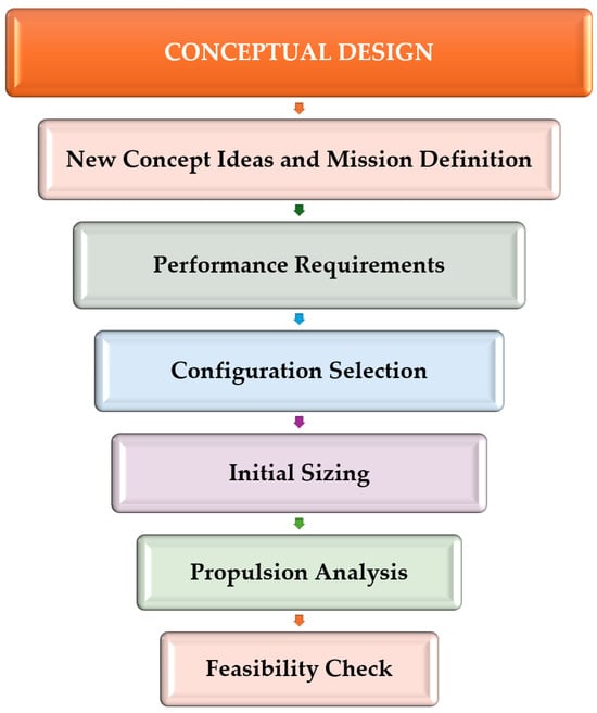
Figure 1.
The stages of conceptual design of the UAV.
This important stage begins with a clear definition of the UAV’s flight mission, where precise objectives are established, such as the main purpose and operating environment. The unmanned aircraft in this study is intended for a dual mission: search and rescue and video surveillance. To accomplish these missions, the drone uses a thermal module, enabling the detection of thermal signatures [39,40]. With the help of the thermal module, detection based on temperature differences can be achieved, which is essential in search and rescue missions. This technology allows for the identification and clear visualization of human thermal signatures, even in the dark, through dense smoke, or in zero visibility conditions, thus optimizing the speed of intervention [39,40]. The control and monitoring of the UAV model is carried out through the ground control station, which provides the command and telemetry link. The performance requirements stage is the connection between the operational purpose of the UAV (established when defining the mission) and the physical and engineering specifications required for design. The technical parameters that are important for the UAV model to perform search and rescue and surveillance missions efficiently are: endurance (flight time), range, operating altitude, and required speeds (cruise/maximum). This stage aims to transform the abstract objectives of the mission into rigorous technical parameters that are necessary for the sizing of the aircraft [38,41]. First, the autonomy of the UAV is estimated. In the case of the model analyzed, the minimum continuous flight time required to accomplish the specific mission is at least 30 min.
The maximum range of the UAV model is 100 km, depending on the capacity of the ground control station. Another important aspect at this stage is establishing the aeronautical regulations that apply to the solar UAV model. Compliance with aeronautical regulations is mandatory to ensure that the UAV is reliable and legal in airspace [42]. The UAV model is classified as Class C2 in terms of construction (maximum take-off weight less than 4 kg) and in the specific category in terms of operations (maximum range of 150 km and maximum operating altitude of 500 m). At this stage, the flight speeds are not known specifically, but they can be approximated within a range based on existing UAV aircraft [19,43,44,45]. Thus, the cruising speed range is between 12 and 20 m/s, and the maximum speed is between 25 and 30 m/s [19,43,44,45].
The initial design stage required the UAV system to be of the fixed-wing type, as the requirement to achieve an operational range of 150 km in the specific category necessitates high aerodynamic efficiency and high cruising speed. A multi-rotor model would not have been able to support the weight of approximately 4 kg over such a long distance. Consequently, the basic design, a sketch of the UAV model, was initiated at this stage (Figure 2).
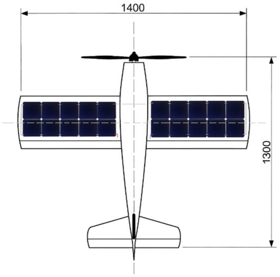
Figure 2.
Sketch of the solar aircraft (dimensions in mm).
Estimating the total mass and sizing during the conceptual design stage is a fundamental procedure, with the main purpose of establishing the basic parameters of the solar UAV before moving on to the next stages of design. In the conceptual phase of UAV development, this process is based on proportional relationships and empirical data from other solar UAV systems. Estimating the mass for a fixed-wing UAV is an important step in conceptual design. The ratio between empty mass and maximum take-off mass (WE/WTO) is set at 0.85 based on reference data [46,47,48] from conceptual aircraft design. Therefore, the UAV will carry a payload of approximately 500 g (thermal module), and the maximum takeoff mass of the UAV model is calculated using relation 1 [46,47,48] to be approximately 3.33 kg.
The starting point for the design of the UAV model was dictated by the power generation system: the use of 20 photovoltaic cells measuring 0.125 m × 0.125 m, resulting in a total solar surface area of 0.31 m2. Thus, to allow space for the wing structure, control surfaces, and edges (achieving a fill factor of approximately 75%), the wing area (Sw) was set at 0.42 m2.
The selection of the wing chord (c) was an important step in the design of the UAV, dictated by the direct requirement to integrate the photovoltaic system. The chord was dimensioned at 0.3 m to accommodate two rows of 0.125 m solar cells across its width. This width (0.25 m) required additional space to accommodate the aerodynamic profile, the internal structure of the wing. Once the chord length (C) was set at 0.3 m and the cells were arranged in two rows, the wingspan (B) could be calculated using Equation (2), resulting in a value of 1.4 m.
Although the fuselage length is generally between 70% and 90% of the wingspan [49,50] and is often between 4 and 6 times the mean aerodynamic chord [20,50], the upper value is 1.26 m for the fuselage length (90% of the wingspan), as this comfortably falls within the range of 4–6 times the CMA and provides the necessary volume to accommodate the battery and electronic equipment, as well as providing the rigidity required to support the wings and tail.
In preliminary design, the wing position is usually defined as a percentage of the fuselage length [51,52], measured from its tip, with typical values between 25% and 35%. For the UAV model, the minimum value was chosen, setting the leading edge of the wing at 25% of the fuselage length (0.315 m). The maximum height of the fuselage was set at 12% of the total fuselage length, resulting in 0.152 m. This value is optimal because it positions the fuselage fineness factor at the ideal value of 8.33, which falls within the range recommended (8–12) by studies in the field [20,50] to minimize forward resistance [20,50].
The surface area of the ailerons was dimensioned using a chord of 12% of the wing chord (approximately 0.036 m), and the specific length of the aileron was 0.638 m. The aileron span was chosen to cover approximately 90% of the wing’s half-span, ensuring effective lateral (roll) control over the entire outer section.
Equation (3) is used in conceptual design to express the horizontal tail volume for the UAV model as
Considering the horizontal tail volume ratio (VHT) of 0.5 [45,53,54], and the horizontal tail moment arm (lHT) was set to 0.94 m for the UAV model, the horizontal tail area (SHT) can be determined using Equation (3), and the calculated value is 0.06 m2.
For the UAV model, the vertical tail moment arm (lVT) was 0.94 m, and the vertical tail volume ratio (VVT) was set at 0.03 [20,45,53,54]. The vertical tail area (SVT), calculated using Equation (4), has a value of 0.018 m2.
The main geometric parameters of the UAV model, resulting from the dimensioning process, are described in Table 2.
Table 2.
Geometric characteristics of the UAV model.
During the propulsion evaluation stage, the appropriate propulsion system is selected and dimensioned to meet the specified performance requirements and flight missions, such as the maximum speed and range of the UAV model. A brushless DC motor will be used due to its superior power-to-weight ratio and high efficiency and reliability [55,56,57], which are essential for meeting the traction and range requirements specific to the UAV model. In conclusion, when choosing the motor, it is imperative to size the system correctly, considering the total mass of the UAV (WTO = 3.3 kg) and correlating the performance of the brushless motor with critical related elements, such as the propeller, battery, and ESC (Electronic Speed Controller).
The final stage of conceptual design, the feasibility and aeronautical regulations compliance check, serves as a final filter to confirm that the proposed solution (the solar UAV model) is realistic and legal (according to aeronautical standards) before moving on to the preliminary design stages. This stage consolidates the conceptual design, confirming that the performance and physical dimensions of the components align with the flight mission objectives (search and rescue and video surveillance), while ensuring compliance with all applicable aeronautical regulations (those established by EASA) to enable the legal operation of the UAV model. The final result of the conceptual design stage is a basic sketch of the UAV model configuration and a set of estimated performance parameters/dimensions, which will serve as a starting point for the next refinement stage.
4. Preliminary Design
The preliminary design process for the solar UAV model goes through a six-step iterative decision cycle, beginning with preliminary aerodynamic analysis, continuing with the establishment of internal structures for the main components and the definition of the solar propulsion/power system, and ending with the integration of the electro-mechanical subsystems and additive manufacturing planning (Figure 3).
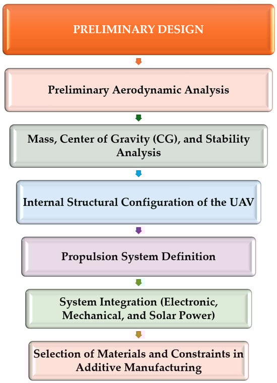
Figure 3.
Stages of preliminary UAV design.
The aerodynamic profile of the wing was chosen to be the MH-104 profile [58,59], having a relatively high thickness of 15.28%. This MH-104 airfoil [58,59] was chosen because it offers a high theoretical fineness ratio (Lift/Drag) (approximately 100 at an angle of attack of 7°), which indicates an optimal balance between the generated lift coefficient (CL) and the drag coefficient (CD). This aerodynamic profile was also chosen for the wing construction for technical and technological reasons related to the manufacture of the aircraft. As the solar cells are not flexible, they cannot be mounted on the upper surface of the profile due to the curvature of the profile on the upper surface. The thickness of the profile allows the cells to be inserted inside the profile, directly onto the wing structure—spar and wing web. To create the wing profile and surface, after the cells are mounted on the airframe, the wing will be covered with a transparent film that adheres to the ribs to take on the contour of the MH 104 aerodynamic profile (Figure 4a). A symmetrical NACA-0009 profile was chosen for the tail of the UAV model. The choice of the symmetrical NACA-0009 profile (Figure 4b) for the tail is a validated solution in UAV development [60,61,62], as it offers minimal drag in cruise flight while ensuring a fast and controllable response by generating lift without its own pitch moment, which is crucial for UAV stability. The digital modeling of the wing geometry (Figure 4c) and the UAV model (Figure 4d) was performed in the XFLR5 v6.55 software system [63], using the established dimensions (according to Table 2) and the selected airfoil as input data for the analysis of aerodynamic performance.
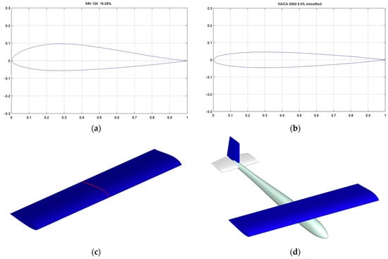
Figure 4.
Modeling the UAV using the XFLR5 software system [59]: (a) MH 104 airfoil for the wing; (b) Airfoil for the UAV’s tail surfaces; (c) Digital model of the wing; (d) Digital model of the complete aircraft.
The preliminary aerodynamic analysis of the solar UAV model will be performed in the XFLR5 software system, following the steps shown in Figure 5a. The second stage of the aerodynamic analysis consisted of determining the Reynolds number (relation 5) based on flight conditions. The kinematic viscosity (υ) was calculated for an altitude of 500 m and a temperature of 20 °C, establishing a value of m2/s.
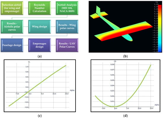
Figure 5.
Solar UAV Preliminary Aerodynamics: (a) Aerodynamic calculation methodology for the UAV model [19]; (b) UAV pressure coefficient distribution (angle of attack 15°); (c) Lift coefficient (CL) vs. angle of attack (alpha); (d) Drag coefficient (CD) vs. angle of attack.
Using this value for dynamic viscosity m2/s together with a cruising speed of 15 m/s and an average aerodynamic chord of 0.3 m, the relevant Reynolds number (relation 5) for the UAV model was determined to be 291074, which will be used in the preliminary analysis in the XFLR software.
The aerodynamic analysis of the UAV model was performed by evaluating the performance for a wide range of angles of attack, varying between −8° and 15°. Specifically, the distribution of the pressure coefficient on the surface of the UAV model at an angle of attack of 15° is illustrated in Figure 5b. The pressure coefficient (Cp) gradient reaches its maximum value at an angle of attack of 15°. This intensification of the pressure difference between the upper and lower surfaces is a direct indicator of the maximum lift generated, which, according to the simulation, is also reached at this angle of incidence. An understanding of the variation in aerodynamic coefficients (CL and CD) at each angle of attack is fundamental to establishing the initial performance of the UAV model and planning flight tests. According to the lift curve (Figure 5c), the lift coefficient (CL) for the entire UAV reaches a value of approximately 1.05 at an angle of attack (alpha) of 15°, which represents the upper limit of the aerodynamic analysis. The CL vs. alpha curve is linear throughout the analyzed range (up to 15°), indicating predictable and stable aerodynamic behavior in cruise flight, significantly simplifying the design and intervention of the control system (autopilot). Simultaneously, the drag curve (Figure 5d) shows that the drag coefficient (CD) increases parabolically with the angle of attack, reaching a value of approximately 0.08 at the same angle of attack of 15°.
To establish the center of gravity (CG) of the UAV model and verify the stability of the UAV model, the online software tool Aircraft Center of Gravity Calculator [64] was used. This center of gravity calculation was based on the preliminary dimensions of the wings and tail (predefined in the conceptual design) and initial mass estimates of the subsystems, as detailed modeling of all electronic components is not complete at this stage.
After entering the main geometric dimensions of the wing and tail into the aerodynamic center of gravity calculator [64], a Static Margin of 12% was imposed on the UAV model; this value provides good stability, ensuring a quick and efficient return to horizontal flight after disturbances, which simplifies the intervention of the control system (autopilot). The final configuration of the UAV model resulted in a sketch (Figure 6a) that validates the position of the Centers (CG and NP), confirming that the 12% margin achieves an optimal balance between stability and reasonable maneuverability, essential for solar UAV-specific cruise missions. Figure 6a shows the relative positions of the Center of Gravity (CG), Neutral Point (NP), and Aerodynamic Center (AC) on the mean aerodynamic chord (MAC). This diagram validates the longitudinal static stability, as the calculated position of the CG is in front of the NP, ensuring the required stability margin of 12% necessary for stable and easily controllable flight. In addition, from the analysis of the Pitch Moment Coefficient vs. Angle of Attack graph (Figure 6b), resulting from the XFLR5 software system, it can be concluded that the UAV model is longitudinally static stable [65,66].
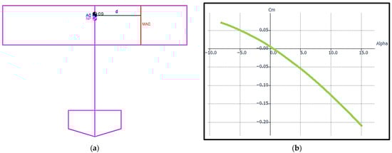
Figure 6.
Solar UAV Preliminary Aerodynamics: (a) Aerodynamic calculation methodology for the UAV model [19]; (b) UAV pressure coefficient distribution (angle of attack 15°).
Throughout the entire aerodynamic analysis range (−8° to 15°), the curve descends steadily (the slope is negative). As the angle of attack (alpha) increases, the pitch moment coefficient (Cm) decreases continuously (from 0.05 at alpha-5° to −0.21 at alpha = 15°). A negative slope means that if an external disturbance accidentally increases the UAV’s angle of attack (positive movement), the aircraft automatically generates a negative pitch moment (nose down). This moment acts as a restoring force, pushing the UAV back to its equilibrium position [65,66]. The negative slope visually confirmed by the graph validates the 12% Static Margin considered, thus the UAV is longitudinally stable and will require minimal intervention from the autopilot to maintain cruise flight.
During the configuration stage of the internal structure of the UAV, the essential structural architecture is defined using an optimal combination of commercial materials and 3D printed parts. The following section details the internal structural architecture of the UAV, with a particular focus on the main components and design elements that ensure a rigid, mass-optimized structure that facilitates the efficient mounting and integration of solar cells on the wing. The wing will be reinforced with two spars, the main spar will be made of a square carbon fiber bar (which takes up most of the bending force), and the secondary spar will be a C-profile, 3D printed from PLA, specially designed to provide the optimal bonding surface needed for mounting the solar cells. The wing uses a hybrid design, combining a rigid main spar and stringers made of square carbon bar. The 3D-printed PLA ribs maintain the aerodynamic shape of the wing and are designed with lightening holes and integrated channels for routing cables from the solar and electronic subsystems. The choice of a straight wing provides simplicity in design, production, and assembly. This design is most efficient to print modularly in components, simplifying the 3D printing process, which contributes to a drastic reduction in manufacturing time and ease of repair. The 3D-printed ribs are provided with lightening holes as a direct application of the principle of minimizing the structural mass of the UAV model, a design strategy for additive manufacturing that ensures the removal of non-essential material from low-stress areas and the concentration of material around stressed areas, thus helping to maintain the total mass of the aircraft at 3.3 kg. The main spar is made of carbon fiber tube, a solution chosen to ensure an optimal strength-to-weight ratio. This spar is positioned at the maximum thickness of the aerodynamic profile (maximum chord), a decision that maximizes the moment of inertia of the section and, implicitly, provides optimal bending strength. The secondary spar, which has a C-shaped profile and is made using 3D printing, serves to integrate functionality and simplify assembly, while also ensuring the necessary local torsional rigidity in the rear section of the wing. This C-shaped profile acts as a direct and precise support for attaching the ailerons, eliminating the need for complicated fasteners, which validates the efficiency of the integrated additive manufacturing technique in the wing design.
The fuselage will be manufactured from PLA using 3D printing, in line with the dimensions established during the conceptual design phase. Because of the 3D printer volume, the fuselage will be split into modules and then put together. Structurally, it will have three key areas: an upper wing mounting area, a reinforced front area for attaching the electric motor, and a rear area with specially designed mounting fixtures for the tail. The fuselage shell will be made of 3D-printed PLA with a thickness of 1 mm [19,20]. This thickness ensures the necessary torsional and shear rigidity, and the structure will be reinforced with internal frames. These frames serve to provide local stiffening and act as bonding surfaces to join the fuselage sections, which are cut according to the volume limits of the 3D printer. The monocoque structure of the fuselage is preferred in this 3D-printed design because it maximizes the internal volume available for the functional integration of electrical components and provides the excellent torsional rigidity required for stability, all of which contributes to minimizing structural mass and, implicitly, achieving optimal energy efficiency. The monocoque structure of the fuselage is modular, consisting of 3D-printed sections, which is essential to comply with the limited dimensions of the printer and optimize manufacturing time. The frames have been integrated at the ends of each section and serve to ensure increased local rigidity, facilitate perfect geometric alignment between sections, and allow for quick maintenance and repair by replacing the damaged section.
The tailplane, both horizontal (elevator and stabilizer) and vertical (rudder and stabilizer), will be entirely 3D printed from PLA. Both subsystems will have a 1 mm thick outer shell, reinforced with internal ribs printed directly onto the structure at a 45° angle (to increase shear strength). Each tail will be clearly divided into a fixed part and a movable part, ensuring the necessary aerodynamic control. The decision to eliminate the landing gear and opt for manual launch and belly landing is an optimal strategy for streamlining the UAV design. By eliminating the landing gear and adopting the manual launch/belly landing strategy, the UAV directly benefits from a significant reduction in total mass and minimization of parasitic drag, which decisively improves aerodynamic finesse and cruise flight range.
The stage of establishing the propulsion system of the UAV model is important in the preliminary phase, as it determines not only performance but also a significant part of the total mass of the UAV. The main objective of this stage is to select a system that ensures efficiency in cruise flight for the UAV model, supported by the solar source, and adequate power for take-off and maneuvers.
The UAV model in this study will be in the category of Electric Glider, Park Flyer & Slow Flyer, with a Power to Weight Ratio (PWR) between 66 W/kg and 132 W/kg [67]. Based on the Power to Weight Ratio, the SunnySky X2820 V3 860 KV motor [68] meets this condition, ensuring that the performance of the aircraft is geared towards slow, stable, and efficient flight. By choosing an average PWR value of 100 W/kg and knowing the maximum take-off weight of the UAV, the maximum design power can be determined using relation 6.
Selecting an electric motor with higher power (960 W) is an essential strategy for operational safety and increased reliability. This power margin ensures operation at only 30–40% of motor capacity, preventing overheating, eliminating the risk of forcing the motor to maximum load, and implicitly reducing thermal stress on components. This selection significantly extends the life of the ESC and battery of the UAV model.
The electrical power consumed (Pc) is a function of the necessary mechanical power (Pm) divided by the total efficiency of the propulsion system (ηp = 0.7). Mechanical power (Equation (7)) is determined by the aircraft’s weight (32.37 N), cruise speed (Vc = 20 m/s), and aerodynamic efficiency (L/D = 10):
The electrical power consumed (Pc) by the UAV model is determined by the following Equation (8):
A reference speed of 15 m/s (Indicated Air Speed, IAS) is used for preliminary aerodynamic analysis (in the XFLR5 software system), but for the final calculation of electrical power consumed (Pc), the upper limit of the cruise range (20 m/s) is applied. This speed of 20 m/s represents the operational speed necessary to maintain efficiency, while ensuring the margin of stability and control necessary to counteract the gusts and turbulence inherent in search and rescue missions in mountainous areas for which the aircraft is designed. This value confirms that the maximum take-off weight of 3.3 kg requires approximately 92.5 W of power to maintain stable horizontal flight in cruise mode for the UAV model.
The sequence of integrating the electronic components begins with the selection of the battery, then the motor and voltage determine the current requirements for the ESC, and finally the torque for the propeller selection, thus ensuring that the entire system is harmonized for the weight of the UAV model (3.3 kg).
The battery selected for the UAV model is LiPo GENS ACE [69], with the following characteristics: capacity: 5000 mAh, voltage (Vn): 14.8 V, C rate: 60 C, weight: 418 g. The selection of a 4 S (14.8 V) battery with a capacity of 5000 mAh (5 Ah) is justified by the power requirement and the autonomy objective (minimum 30 min). The cruising current (Icruise) is an essential value for calculating your UAV’s endurance and efficiency (relation 9).
The autonomy of the solar UAV system is calculated using the battery capacity (C) and the constant discharge current (Icruise) using Equation (10).
By using a 5000 mAh battery, the minimum requirement of 30 min of autonomy for the UAV model is exceeded and a higher autonomy of approximately 48 min without solar contribution is ensured, providing a safety margin of 18 min. The choice of the Gemfan propeller with dimensions of 13 × 6.5 inches [70] is justified by the thrust requirements of the 3.3 kg UAV model and, at the same time, the data provided by the electric motor manufacturer, who tested and validated the operation of the motor with this propeller model [68], was taken into consideration.
The GENS ACE LiPo battery was selected in accordance with the motor requirements, with a recommendation for a 4-cell battery, and the 5000 mA power was chosen because it represents the maximum energy capacity (Eb—the value of 74 Wh comes from multiplying the nominal voltage and the battery capacity of 5 Ah) necessary to guarantee the flight autonomy required by the mission and to ensure sufficient energy reserve for the operation of systems and sensors in low light conditions or at night.
The ESC selection is based on the relationship 11, as the ratio between maximum peak power (Pp = 900 W) and nominal battery voltage (Vn = 14.8 V):
Therefore, a voltage ESC of 60 A [71] was selected, which aligns very well with the recommendation for the electric motor used. The ESC (60 Amps) was selected because its rated capacity aligns optimally with the technical specifications and maximum peak current requirements of the electric motor used. This selection ensures an adequate safety margin and increases thermal reliability during flight of the UAV model.
The selection of MICRO PDI-2004MG servo controls is justified by the operational requirements of the endurance UAV, offering superior precision, mechanical reliability, and environmental resistance, which are essential for stable control and long-term operation [72]. The servo provides high-precision digital control (crucial for autonomous endurance flight) and maximum mechanical reliability using anodized aluminum alloy gears and CNC-machined aluminum housing, which provides optimal cooling and protection against moisture [72].
The photovoltaic system of the UAV model consists of 20 high-efficiency SunPower cells [73] connected in series, which ensure optimal solar energy capture and a maximum electrical power (Pcells) of 74.4 W (relation 12).
where Pcell_single represents power of solar cells 3.72 W [73].
The autonomy of the UAV model, using the solar system, is calculated with relation 13:
The five scenarios selected for calculating autonomy, the solar coefficient () had values of 0%, 25%, 50%, 70%, and 100%, and the results are described in Table 3.
Table 3.
Autonomy of the UAV model equipped with solar cells.
During cruise flight of the UAV model, the solar cells do not achieve a net charge of the battery, but act as a backup energy source that reduces the total power draw of the motor from the internal battery. Therefore, the solar system reduces the battery discharge rate from 92.5 W to only 40.4 W, thus exponentially extending the time required to exhaust the 74 Wh of stored energy (Eb).
To fully harness this energy, an MPPT (Maximum Power Point Tracker) regulator is needed to boost the voltage from 11 V (generated by the series-connected cells) to the battery charging level of 14.8 V and to constantly optimize the power transfer to the propulsion system [74,75,76]. The selection of the Genasun GVB-8-Li-CV [77] MPPT controller configured at 16.8 V is essential to harmonize the electrical system of the UAV model. Since the 20 solar cells (connected in series) provide 11 V, which is insufficient to directly charge the 14.8 V battery, the controller must perform the voltage boost function to make energy transfer possible. The Custom Voltage (CV) version of the MPPT is set to 16.8 V (4 cells × 4.2 V) precisely to ensure that the LiPo pack reaches 100% of its capacity, using the maximum reserve of 74 Wh to extend the UAV model’s range.
The selection of PLA (polylactic acid) filament for the manufacture of ribs and fuselage sections is justified by the prioritization of the essential endurance requirements of the UAV model. Analysis of UAV models [19,78,79,80,81] manufactured by 3D printing revealed that PLA is a commonly used and validated filament in practice for prototyping unmanned aircraft systems or aerospace structures. PLA filament is preferred because it is easy to print, facilitating a rapid and cost-effective manufacturing process [82,83]. In addition, the material offers excellent structural rigidity, ensuring that parts are warp-free (providing high dimensional accuracy) after 3D printing, which is important for ensuring the alignment of fuselage sections and maintaining the accuracy of the wing profile [82,84]. The volume constraints of the 3D printer require the manufacture of the fuselage sections from PLA in modular sections, a decision that requires the design of precise joints to ensure the alignment and structural integrity of the UAV model.
5. Detailed Design
The detailed design stages (Figure 7) represent the final validation phase, where the project is completed through detailed CAD design for additive manufacturing, structural validation through finite element analysis, subsystem integration (propulsion, solar, avionics), and documentation completion (electrical circuit diagram), thus preparing the UAV model for physical realization.
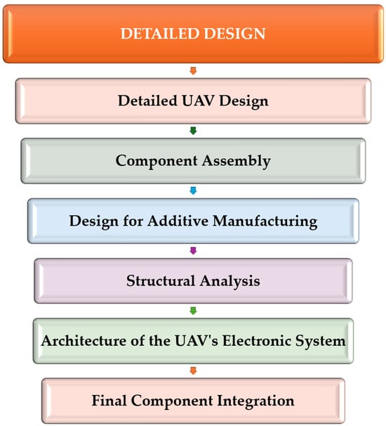
Figure 7.
Detailed design stages for the solar UAV model.
Starting from the digital UAV model, created in the XFLR5 software system (Figure 4d), the components of the aircraft equipped with solar cells were designed in detail in the SolidWorks 2020 software system. The fuselage was mainly designed based on the dimensions determined in the conceptual design, but taking into account the positioning of all the electronic components necessary for the proper functioning of the device—batteries, electrical telemetry systems, servo controls, brushless motor, and others. The design of the fuselage begins with establishing the plans and creating the 1 mm shell. The next step in designing the fuselage is to construct the support wall for mounting the motor in the front of the aircraft (Figure 8a). The wall constructed to hold the motor is 5 mm in thickness and will be manufactured directly to ensure better strength.
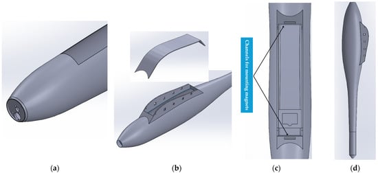
Figure 8.
Detailed design of the aircraft fuselage: (a) Electric motor mounting location; (b) Upper cover and wing-fuselage joint area; (c) The location for positioning the servo controls; (d) CAD model of the fuselage.
Also, for ease of assembly and taking into account technological conditions, a simple method was developed for assembling the wings to the fuselage—the support through which the wings will be embedded in the fuselage (Figure 8b). This support follows the aerodynamic profile of the wing, which makes for easy installation and does not create any aerodynamic impediments. To complete the fuselage structure and restore the aerodynamic characteristics of the entire aircraft assembly, a cover was designed to be mounted above the wing-fuselage joint area. The cover is equipped with channels for insertion and will be glued using magnets for easy installation and removal (Figure 8c). Subsequently, a support bed was created to mount the servo controls inside the fuselage (Figure 8c), and finally, the CAD model of the fuselage was completed (Figure 8d).
The structure of a semi-wing consists of the following structural components: 4 ribs manufactured additively from PLA material with a thickness of 3 mm for stiffening (Figure 9a); a main carbon fiber spar, measuring 10 mm × 10 mm × 680 mm, positioned in the area of maximum thickness of the MH 104 aerodynamic profile; a secondary 3D-printed spar, made of PLA, in the shape of a C-profile, positioned in the trailing edge area of the wing (Figure 9b); 3 square carbon tube stringers, measuring 7 mm × 7 mm × 680 mm, and a round stringer made of carbon fiber. The spars and stringers serve to absorb the forces acting on the wing but also support the solar cells.
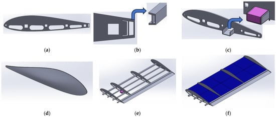
Figure 9.
Detailed design of the aircraft wing: (a) Rib with lightening holes and cable channels; (b) Trailing edge with secondary spar C profile; (c) Housing for the aileron servo control; (d) Wing tip; (e) CAD model of the wing; (f) CAD model of the wing equipped with solar cells.
The spars and stringers are designed to absorb the bending and shear stresses generated by aerodynamic loads, while also providing mechanical support for the structure, including the solar cells. The servo support ribs are derived from the main ribs, but are designed with an integrated support specifically sized for the servos used (Figure 9c). The support is located on the rib and they are 3D printed together, thus significantly improving the assembly’s resistance to vibrations and servo stresses. To optimize the wing shape, wing tips were designed to maintain the selected aerodynamic profile, thereby increasing aerodynamic efficiency and reducing the drag induced at the wing tip (Figure 9d). After the assembly of the components, the complete CAD model of the wing was obtained (Figure 9e), and subsequently, the solar cells (12.5 mm × 12.5 mm in size) were virtually placed on the wing surface (Figure 9f) for visualization and checking (geometric and coverage). The tail design is classic (conventional), inverted T, where the horizontal tail is placed at the bottom, at the base of the vertical tail. In addition to good stability, the classic tail on the UAV model will provide simple and easy structural integration; maintain elevator efficiency by placing it outside the turbulence zone of the wing or propeller [85,86]. Based on the dimensions set out in Table 2, the two tailplanes with mobile surfaces were designed (Figure 10a,b).
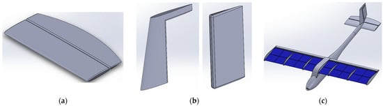
Figure 10.
Detailed design of the UAV model: (a) Horizontal stabilizer and elevator; (b) Vertical stabilizer and rudder; (c) 3D model of the solar UAV.
The digital assembly stage joins all subassemblies (wing, tail, fuselage, solar cells) into the final CAD model of the solar UAV. This step is important in completing the digital model because it allows for precise verification of interfaces and the absence of geometric interference between aircraft components. Consequently, the complete configuration of the equipped aircraft is validated prior to the additive manufacturing design of the UAV model (Figure 10c).
The design stage for additive manufacturing begins with establishing the optimal 3D printing orientation to ensure mechanical strength and minimize support surfaces that can affect weight and surface roughness. In a first step, guide (joint) areas are added to the fuselage sections to ensure correct alignment during physical assembly (Figure 11a). Also, to facilitate stronger and more precise bonding, the fuselage sections are provided with 3 mm thick inner frames at the ends, which increase the contact (bonding) surface and rigidize the joint. Next, the interior structures of the tailplanes are designed with the aim of reducing weight while maintaining rigidity. Thus, the internal structures of the horizontal empennage (Figure 11b) and vertical empennage (Figure 11c) were made of ribs arranged at a 45° angle for 3D printing without supports, but also for good rigidity. The last stage describes the exploded 3D model of the UAV (Figure 11d), which clearly visualizes all components and the division into sections optimized for the 3D printing manufacturing process, fitting within the manufacturing volume of the 3D printer.
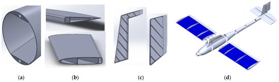
Figure 11.
Design for additive manufacturing of the UAV model: (a) Fuselage section with frames and alignment holes; (b) Horizontal stabilizer and elevator with stringers oriented on 45°; (c) Vertical stabilizer and rudder; (d) UAV model ready for 3D printing.
The structural analysis of the wing was performed in the ANSYS Workbench R2 2021 software system (Canonsburg, PA, USA), Static Structural module, where the total displacements and equivalent stresses under static loads will be determined. Determining the results of the structural analysis is essential to verify that the model design is strong enough to ensure the safety and safe operation of the UAV.
Both materials, the 3D-printed and carbon fiber components of the spar and wing will be modeled as orthotropic materials in the finite element analysis, thus simplifying the definition of mechanical properties to 9 independent elastic constants (Table 4) for each material, and this assumption has been used in recent studies [87,88,89,90].
Table 4.
Orthotropic properties of PLA [91,92,93] and carbon fiber [94,95,96] materials used in finite element analysis.
Based on the mesh convergence analysis, the wing model was discretized with an element size of 1 mm, having 1,319,238 nodes and 310,562 Solid 187 tetrahedral elements (Figure 12a). The structural design load of the solar UAV wing (Ldesign) is calculated using the product [97,98,99] of the load factor (n = 2) and a safety factor (SF = 1.5) and the maximum flight weight (3.3 kg), resulting in the maximum force (97.12 N) that the wing structure must support without breaking.
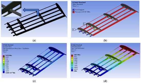
Figure 12.
Finite element analysis of the wing structure: (a) Meshing of the wing model; (b) Setting boundary conditions and applying loads; (c) Distribution of equivalent stresses; (d) Distribution of total deformation.
The design pressure (Pdesign) used in the finite element analysis of the UAV wing structure is calculated by dividing the design load (Ldesign) by the wing area (SW), according to Equation (14).
The boundary conditions imposed in the finite element analysis assume complete fixation (embedding) of the wing structure in the junction area with the fuselage of the UAV model (Figure 12b). The applied load (Figure 12b) consists of the equivalent design pressure of 231.24 Pa, distributed directly on the surface of the internal structural elements (spars, stringers, ribs), in the direction of the lifting force [100,101,102]. Although the wing skin (in this case, the foil) initially absorbs the pressure, its structural role is secondary. The aerodynamic load is essentially transmitted and supported by the main internal components (spar, ribs, and carbon spars). Applying pressure directly to the main internal elements of the wing is a valid technical simplification that is closer to the structural reality. This approach eliminates the need to model the complexity and nonlinearity of the foil, while ensuring that the FEA analysis focuses on the critical stresses that occur in 3D printed or composite materials. The maximum equivalent stress of 14.5 MPa (Figure 12c) occurring at the junction of the secondary spar with the rib (both manufactured by 3D printing from PLA) is well below the maximum bending stress of PLA material, which is 96 MPa [91]. The calculated safety factor of 6.6 confirms the strength of the entire solar UAV structure, demonstrating that the wing can withstand the maximum aerodynamic loads in flight. This high strength is ensured both by the high performance of carbon fiber composites (for spars and stringers) and by the reliable structural contribution of the PLA material used for 3D-printed components. A maximum displacement of 4 mm at the tip of the UAV wing (Figure 12d) is a very small value and indicates good wing structure rigidity. Small displacements are vital for solar UAVs because they maintain aerodynamic shape and ensure flight stability without affecting solar cell performance.
Figure 13 illustrates the electronic architecture of the solar UAV model, highlighting the interconnection of the propulsion, control, and energy generation components. The energy system consists of the 20 solar cells on the wing, the MPPT regulator that maximizes charging, and a LiPO battery that functions as the main power source. The battery supplies the necessary current to the brushless motor via the ESC, thus controlling the thrust of the aircraft. At the same time, the telemetry receiver receives flight commands from the ground and transmits monitoring data, including battery voltage information provided by the LiPO sensor. This integration of the solar system allows for extended endurance of the UAV model.
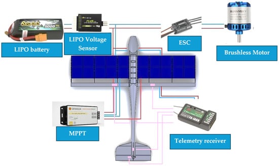
Figure 13.
Electronic interconnection diagram of the energy management and propulsion system of the solar UAV model.
Initial flight tests of the UAV model will be conducted using direct radio control (RC) to validate the aircraft’s basic performance and control surface calibration. Subsequently, the autonomous system will be gradually implemented, including the autopilot, ground control station (GCS) for mission planning, and the thermal module will be integrated for advanced data collection and search and rescue and surveillance capabilities. The final stage of detailed design consolidates digital preparation and validates the UAV model before starting additive manufacturing. This phase begins with a rigorous check of the STL files for 3D-printed components, ensuring quality and the absence of geometric errors. This is followed by final validation of the complete digital model and verification of the functionality of all purchased electronic components. Validation of the electrical diagram of the solar and propulsion system (Figure 13) is also performed to prevent wiring errors. Once all tests are successfully completed, the additive manufacturing stage officially begins with the 3D printing process for all components needed to build the solar UAV model. All these final checks and validations are essential to reduce manufacturing risks and ensure that the digital model translates into a functional UAV aircraft, ready for the assembly and testing stage.
6. Additive Manufacturing and Assembly of the Solar UAV Model
The implementation of the 3D printing process is essential for this study, as it allows for the rapid and efficient manufacture of complex components of the solar UAV model structure, such as ribs, secondary spars, and fuselage sections. The 3D printer used to manufacture the solar UAV components was the Ultimaker S5, a highly reliable 3D printing system known for its medium build volume (330 mm × 240 mm × 300 mm) and good print quality, which are essential for structural components. The essential additive manufacturing parameters required to achieve 3D printing of the solar UAV model components are detailed in Table 5.
Table 5.
3D printing parameters used in the fabrication of UAV model components.
To prepare the files for additive manufacturing, the Ultimaker Cura 5.1.1 software system was used, which allowed the generation of G-code based on 3D printing parameters (Table 5) and ensured compatibility with the Ultimaker S5 printing system. The next step, after preparing the files in the Ultimaker Cura 5.1.1 software system and setting the 3D printing parameters, was to start 3D printing the solar aircraft components, as shown in Figure 14.
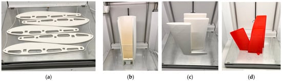
Figure 14.
Printing of UAV model components: (a) Ribs; (b) Fuselage section; (c) Empennage surfaces; (d) Control surfaces.
This additive manufacturing stage has allowed the physical realization of PLA structural components, as follows: ribs (Figure 14a), fuselage sections (Figure 14b), tail surfaces (Figure 14c), and control surfaces (Figure 14d), according to digitally validated geometries. The parameters set ensured that the 3D-printed components had the strength and dimensional accuracy required for the subsequent assembly of the UAV model. Although the total 3D printing time was considerable (107 h and 32 min), the use of a 0.1 mm extrusion layer height was a good decision. This parameter significantly improved surface quality and dimensional accuracy, both of which are essential for the structural joints of the components, important aspects for the manufacture of a UAV prototype. The next step demonstrates the transition from digital design to physical realization, where all components of the solar UAV model have been 3D printed (Figure 15) and are arranged for inspection and assembly.
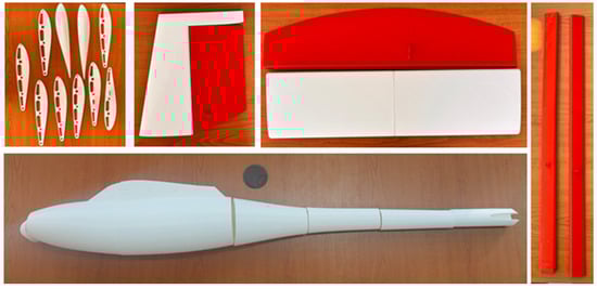
Figure 15.
3D printed components of the solar UAV model.
The final stage is the physical assembly of the UAV model, which begins with the main structure: the fuselage. This is achieved by bonding the 3D printed sections, starting with Section 1 (the front) and progressing to Section 7 (the tail). This sequence guarantees the correct alignment of the fuselage axis and the efficient transfer of structural loads. The mounting of the motor (Figure 16a) is a priority functional step that must be performed before gluing Section 1 to Section 2, as the geometry of the 3D-printed parts does not allow for its subsequent installation. An additional essential activity that must be performed before gluing Section 1 and Section 2 is gluing the magnets into the fuselage cover housing and the fuselage structure, as shown in Figure 16b. The bonding of the fuselage sections, printed from PLA, is performed using cyanoacrylate adhesive, which is an effective choice and provides quick adhesion for the structural sections of the UAV model.
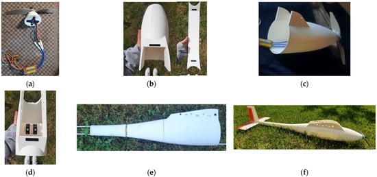
Figure 16.
Assembling the fuselage components: (a) Mounting the electric motor; (b) Inserting the magnets; (c) Bonding the first two fuselage sections; (d) Installing the servo controls; (e) Joining sections 3-4-5; (f) Final fuselage model with empennage mounted.
The motor was directly fixed with screws into the wall of Section 1, and then the ESC was connected to the motor, followed by the installation of the propeller (Figure 16c). The installation of the servos (Figure 16d) that control the elevator and rudder must be performed in the specially designed location in Section 3 of the fuselage before assembling the adjacent sections, due to access constraints imposed by the geometry of the 3D printed parts. To ensure precise structural alignment of the fuselage, all sections are placed in order and centered using two cylindrical aluminum tubes. These tubes (Figure 16e) pass through the 8 mm diameter channels (upper and lower) of the sections, assuring perfect coaxiality of the central axis during the joining process. The next step is to mount the tail on Section 7 of the fuselage (Figure 16e), a process that began with the fixed parts (horizontal stabilizer and vertical stabilizer) being glued in place. By fixing the moving parts (elevator and rudder) with fiberglass tape, the structure of the UAV model fuselage is structurally and functionally complete, preparing the aircraft for wing integration.
The assembly of the wing structure is initiated with the precise positioning of the ribs on the longitudinal elements (both on the stringers and on the main spar), an activity that is completed by establishing the correct distances between the ribs across the entire span (Figure 17a), thus ensuring a rigid and flat base for the subsequent positioning of the solar cells. Before mounting the solar cells on the wing structure, the voltage of each cell will be checked individually, followed by a series connection test using a multimeter to confirm the increase in total voltage. Subsequently, blocks of two cells connected by electrical connections were glued to the structure, after which the final electrical connections were made between them to form the solar circuit of the wing (Figure 17b). The photovoltaic cells are bonded using a special adhesive and are attached directly to the flat surfaces of the stringers and spars, which provide the necessary high-strength structural surface. The solar cells are covered with a heat-shrinkable polymer plastic film to provide protection against moisture and minimize parasitic resistance. The electrical connection of the solar cells was made by soldering, successively connecting the positive and negative terminals in a series circuit to achieve the required operating voltage, both methods contributing to the durability and integrity of the solar system under the vibration and dynamic loads encountered in flight conditions of the UAV model. Thermal management was addressed through integrated passive solutions, including ventilation areas integrated into the 3D-printed structure of the fuselage and wing for cooling critical electronic components (ESC/battery), as well as the use of heat-shrinkable film on the solar cells, with the aim of stabilizing photovoltaic efficiency and ensuring the durability of the system in the face of thermal and vibrational loads.
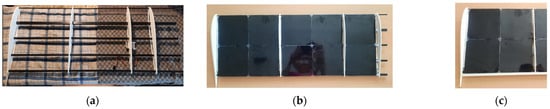
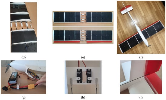
Figure 17.
Assembling the wing and electronic components: (a) Assembling the ribs and main spar; (b) Mounting and connecting the solar cells; (c) Gluing the secondary spar; (d) Covering with laminate film; (e) Assembly of the ailerons; (f) Assembled UAV model; (g) Connection of the ESC-LIPO battery; (h) Connection of the servo control rods; (i) Connection of the aircraft rudder rod.
After mounting the solar cells, the wing is stiffened by bonding the secondary spar to the trailing edge (Figure 17c), and the final step is to wrap it with transparent laminating film (Figure 17d), which serves to reproduce the airfoil of the wing and protect the solar cells from impurities. After covering the wings, the left and right ailerons (Figure 17e) are mounted behind the secondary spar, ensuring functional control of the roll of the solar UAV. Subsequently, the two half-wings (left and right) are joined using 3D-printed connecting pieces profiled after the spars and stringers, ensuring perfect mechanical alignment and structural integrity of the entire wing. Finally, after completing all the assembly steps for the fuselage, tail, and wing, the result is the assembled solar UAV model (Figure 17e), integrating all structural components. The power system of the UAV is designed to operate in hybrid mode, where the battery is connected in parallel to both the ESC system (Figure 17g) and the wiring coming from the MPPT controller. The solar circuit begins with the cells mounted in series to increase voltage, and the solar panel assembly connects to the MPPT input, which regulates the voltage and protects the battery. On the control side, the receiver serves as an interface, taking signals from the remote control and transmitting them to the servos (ailerons, elevator, rudder) and to the ESC system. This parallel connection allows the MPPT to charge the battery from solar energy and, simultaneously, the battery to power the propulsion, thus ensuring the autonomy and functionality of the entire system. The servo connections (Figure 17h) that operate the ailerons, elevator, and rudder (Figure 17i) are connected directly to the receiver, which serves as the main control interface. Its role is to decode the input signals received via the remote control and transmit them as precise control signals to the servomechanisms, thus ensuring the deflection (movement) of the control surfaces. Finally, the structurally and electronically assembled solar UAV model is ready for the next stages of development—control calibration, ground tests, and then flight tests—stages that will be carried out in full in a future study.
7. Discussion
Figure 18 summarizes in detail the main technical characteristics and operational performance of the developed solar UAV model. Based on these data, corroborated by the comparative analysis presented in Table 1, a critical assessment of performance can be made, thus establishing the feasibility and competitive advantage of the proposed solution in relation to existing solutions on the market.
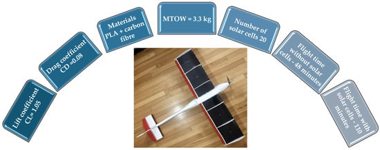
Figure 18.
Characteristics and performance of the solar UAV model.
It is noted that the solar UAV model developed in this study demonstrates good structural efficiency, being much more compact (b = 1.4 m) and lightweight (MTOW = 3.3 kg) compared to endurance solar UAVs. This reduced mass is achieved exclusively through custom design facilitated by additive manufacturing. The aerodynamic coefficients determined in the XFLR software system are close in value to the results of previous studies [32,35], but are obtained at a smaller structural scale (0.42 m2—wing area), which is essential for maintaining a minimum power requirement. The solar system of the developed model demonstrates superior power density by using only 20 high-efficiency SunPower cells, capable of delivering 74.4 W (3.72 W/cell). The proposed photovoltaic system validates its novelty (efficient integration) compared to solutions that require a much larger number of cells to achieve similar power (the model using 224 cells), while ensuring constant operating voltage and minimizing the associated structural space and mass.
It is observed that the cruising power of the UAV model (92.5 W) is managed by the solar input of the cells installed on the aircraft. The methodological novelty consists of validating the critical power threshold hypothesis (set at Pd ≤ 40 W). It has been demonstrated that at an operational efficiency of 70% (a realistic scenario for solar cell efficiency), solar input reduces battery power demand (Pd) to a value that is at the 40 W threshold. Reaching this value represents the critical threshold that guarantees (according to the analytical model) that the UAV operates in the area of exponential autonomy growth, extending the flight time from the base of 48 min to approximately 110 min.
The most important performance indicator for solar aircraft (used to evaluate the maximum theoretical potential) is the efficiency of autonomy relative to mass (Tmax/MTOW), which has a value of 74 min/kg for the solar UAV model developed in this study. The value of this indicator (74 min/kg) demonstrates that, in terms of theoretical efficiency, the proposed design significantly exceeds the performance of reference aircraft (which have a ratio between 37.5 min/kg and 52.5 min/kg), confirming the superiority of the manufacturing method of the model in achieving an optimal energy density per unit mass. The success of the modeling demonstrates the feasibility of achieving a maximum theoretical autonomy of approximately 245 min, thus validating the central hypothesis of the study.
Another innovative aspect of the study is the demonstration that the integrated additive manufacturing technique, combined with a functional assembly methodology for UAV components, is not only a rapid production method but also an integral part of the energy solution. This approach is based on a validated hybrid structural design (PLA and carbon fiber), using specific DFAM (Design for Additive Manufacturing) strategies. This allows for minimal structural mass and seamless solar cell integration, both of which are essential for achieving optimal battery power output.
The 3D printing process strikes a balance by reducing manufacturing time/cost (eliminating molds) without compromising the structural integrity of the UAV model. FEA has shown that, under maximum flight loads, the maximum equivalent stress achieves a value of 14.6 MPa, which is six times lower than the structural strength of PLA material. This large structural margin is vital to compensate for factors inherent in additive manufacturing, including part anisotropy (variation in strength in the three directions) and the risk of classic 3D printing defects (voids or incomplete adhesion between layers of extruded material), which can locally affect the structural integrity of 3D-printed components. Thus, it is demonstrated that maintaining safety at such a low structural mass cannot be provided simultaneously by existing methods, requiring an integrated additive manufacturing technique that validates a lightweight structure capable of absorbing both the flight loads of the UAV model and the uncertainties associated with anisotropic material.
The Additive Manufacturing (AM) approach offers a critical cost-time efficiency advantage over traditional manufacturing methods (e.g., fiberglass or carbon fiber composite layering) using molds. As a result, the total manufacturing and assembly time for the UAV model is approximately 170 h, a significantly reduced time compared to conventional processes involving the design and production of molds required for composite materials. The AM methodology eliminates these expensive molds, uses a mid-range printer and standard material, resulting in much lower costs and increased design flexibility. This cost-time advantage reinforces the justification for the study, as it demonstrates the economic feasibility and speed of UAV development.
The essential criterion of the solar UAV model will be the validation of the energy model by reaching and maintaining the power extracted from the battery below the critical threshold, which will determine the extended endurance necessary to cover vast search and rescue areas. Another important criterion is the confirmation of the structural integrity of the design achieved through additive manufacturing, demonstrating that the reserve factor and passive thermal management solutions ensure the durability of the UAV in the face of turbulence and dynamic loads. Operational success will be confirmed by the ability of the autopilot to autonomously execute the surveillance mission and by the functionality of the thermal imaging module to collect relevant images, thus ensuring the ability of the system to quickly and accurately identify critical targets (rescue targets) in rough terrain.
8. Conclusions
The use of renewable energies, especially solar energy, is essential for environmental protection. The application of solar energy in the aerospace industry marks a significant technological advance, offering advantages such as a clean and free energy source and increased autonomy in surveillance missions. However, there are also disadvantages, such as dependence on weather conditions and high initial costs of equipment.
This study demonstrated the feasibility of using additive manufacturing (3D printing) during the three stages of design (conceptual, preliminary, and detailed) of the solar UAV. This approach offered a major advantage, allowing for the rapid customization of complex components and their efficient production, which are vital aspects for innovation in aerospace structures. The solar UAV model was subsequently validated by a preliminary analysis of aerodynamic coefficients in XFLR software, and structural analysis (FEA) confirmed that the hybrid structure (PLA filament and carbon fiber components) excellently resists design and operation loads.
The implementation of the solar system is essential because, even under realistic flight conditions (70% efficiency), solar net power reduces battery consumption from 92.5 W to just 40.4 W. This reduction in energy deficit exponentially increases the autonomy of the UAV, extending the mission duration from 48 min (without solar cells) to approximately 110 min (with solar cells), thus validating the hybrid design of the developed model.
The correct execution of the design stages (conceptual, preliminary, and detailed) ensured that the design for additive manufacturing (DFAM) was optimal, eliminating most structural and interface errors in the digital phase. As a result, the physical manufacturing process and assembly of the UAV components proceeded without major problems, confirming the effectiveness of the sequential design method. Using this approach, UAV prototypes can be obtained quickly in a considerably reduced time, eliminating the need for mold and traditional manufacturing processes. This allows additive technologies to be used to rapidly implement innovations and emerging technologies directly into the life cycle of aeronautical systems.
In conclusion, this study demonstrated the feasibility of building a solar UAV by successfully completing all the steps necessary for the development of an aeronautical system. These stages included conceptual, preliminary, and detailed design, followed by 3D printing and component assembly. Future research will include ground testing and flight testing to validate aerodynamic and energy performance. These stages will be followed by the implementation of the autopilot and ground control station (GCS), which are essential for accurate flight planning. In addition, the thermal module will be implemented for the efficient deployment of complex missions (such as search and rescue or video surveillance) of the solar UAV model.
Author Contributions
Conceptualization, I.N. and S.-M.Z.; methodology, I.N. and S.-M.Z.; software, I.N. and S.-M.Z.; validation, S.-M.Z.; investigation, I.N. and S.-M.Z.; resources, I.N. and S.-M.Z.; data curation, I.N. and S.-M.Z.; writing—original draft preparation, I.N. and S.-M.Z.; writing—review and editing, I.N. and S.-M.Z.; supervision, S.-M.Z.; project administration, I.N. and S.-M.Z.; funding acquisition, I.N. and S.-M.Z. All authors have read and agreed to the published version of the manuscript.
Funding
This work was financially supported by the Transilvania University of Brasov.
Institutional Review Board Statement
Not applicable.
Informed Consent Statement
Not applicable.
Data Availability Statement
All data generated or analyzed during this study are included in this published paper.
Conflicts of Interest
The authors declare no conflicts of interest.
References
- Gajdzik, B.; Wolniak, R.; Nagaj, R.; Žuromskaitė-Nagaj, B.; Grebski, W.W. The Influence of the Global Energy Crisis on Energy Efficiency: A Comprehensive Analysis. Energies 2024, 17, 947. [Google Scholar] [CrossRef]
- Lu, Y.; Khan, Z.A.; Alvarez-Alvarado, M.S.; Zhang, Y.; Huang, Z.; Imran, M. A Critical Review of Sustainable Energy Policies for the Promotion of Renewable Energy Sources. Sustainability 2020, 12, 5078. [Google Scholar] [CrossRef]
- Zhu, X.; Guo, Z.; Hou, Z. Solar-powered airplanes: A historical perspective and future challenges. Prog. Aerosp. Sci. 2014, 71, 36–53. [Google Scholar] [CrossRef]
- Liscouët-Hanke, S.; Mir, M.; Bashir, M. Exploration of Solar Power System Integration for Sustainable Air Transportation—A Case Study for Seaplane Air Taxi Operations. Aerospace 2025, 12, 164. [Google Scholar] [CrossRef]
- Boucher, R.J. History of Solar Flight. In Proceedings of the AIAA/SAE/ASEE 20th Joint Propulsion Conference, Cincinnati, OH, USA, 11–13 June 1984. [Google Scholar]
- Boucher, J.R. Sunrise, the World’s First Solar-Powered Airplane. J. Aircr. 1985, 22, 840–846. [Google Scholar] [CrossRef]
- Al-Ezzi, A.S.; Ansari, M.N.M. Photovoltaic Solar Cells: A Review. Appl. Syst. Innov. 2022, 5, 67. [Google Scholar] [CrossRef]
- Zhao, T.; Zhang, Y.; Wang, M.; Feng, W.; Cao, S.; Wang, G. A Critical Review on the Battery System Reliability of Drone Systems. Drones 2025, 9, 539. [Google Scholar] [CrossRef]
- Isaienko, V.; Kharchenko, V.; Matiychyk, M.; Lukmanova, I. Analysis of layout and justification of design parameters of a demonstration aircraft based on solar cells. E3S Web Conf. 2020, 164, 13007. [Google Scholar] [CrossRef]
- Sornek, K.; Augustyn-Nadzieja, J.; Rosikoń, I.; Łopusiewicz, R.; Łopusiewicz, M. Status and Development Prospects of Solar-Powered Unmanned Aerial Vehicles—A Literature Review. Energies 2025, 18, 1924. [Google Scholar] [CrossRef]
- Jenie, Y.I.; Pardomoan, G.Y.; Moelyadi, M.A. Development of an Automatic Solar Tracker Control System for a Tandem-Winged UAV and Its Implementation Strategies. Drones 2023, 7, 442. [Google Scholar] [CrossRef]
- Nickol, C.L.; Guynn, M.D.; Kohout, L.L.; Ozoroski, T.A. High altitude long endurance air vehicle analysis of alternatives and technology requirements development. In Proceedings of the 45th AIAA Aerospace Sciences Meeting and Exhibit, Reno, CA, USA, 8–11 January 2007; pp. 12653–12669. [Google Scholar]
- Frulla, G.; Cestino, E. Design, manufacturing and testing of a HALE-UAV structural demonstrator. Compos. Struct. 2008, 83, 143–153. [Google Scholar] [CrossRef]
- Zhang, W.W.; Zhang, L.G.; Yan, Z.W.; Wang, L. Structural Design and Difficulties of Solar UAV. IOP Conf. Ser. Mater. Sci. Eng. 2019, 608, 012016. [Google Scholar] [CrossRef]
- İlhan, C.; Çalik, Z. Solar-Powered Uav: A Novel Approach to Conceptual Design. Konya J. Eng. Sci. 2024, 12, 2667–8055. [Google Scholar] [CrossRef]
- Leutenegger, S.; Jabas, M.; Siegwart, R.Y. Solar Airplane Conceptual Design and Performance Estimation. J. Intell. Robot. Syst. 2011, 61, 545–561. [Google Scholar] [CrossRef]
- Liller, J.; Goel, R.; Aziz, A.; Hester, J.; Nguyen, P. Development of a Battery Free, Solar Powered, and Energy Aware Fixed Wing Unmanned Aerial Vehicle. Sci. Rep. 2025, 15, 6141. [Google Scholar] [CrossRef]
- Sonkar, S.; Kumar, P.; George, R.C.; Yuvaraj, T.P.; Philip, D.; Ghosh, A.K. Low-cost development of a fully composite fixed-wing hybrid VTOL UAV. J. Braz. Soc. Mech. Sci. Eng. 2024, 46, 252. [Google Scholar] [CrossRef]
- Pascariu, I.S.; Zaharia, S.M. Design and testing of an unmanned aerial vehicle manufactured by fused deposition modeling. J. Aerosp. Eng. 2020, 33, 06020002. [Google Scholar] [CrossRef]
- Zaharia, S.-M.; Pascariu, I.S.; Chicos, L.-A.; Buican, G.R.; Pop, M.A.; Lancea, C.; Stamate, V.M. Material Extrusion Additive Manufacturing of the Composite UAV Used for Search-and-Rescue Missions. Drones 2023, 7, 602. [Google Scholar] [CrossRef]
- Karlina, A.I.; Balanovskiy, A.E.; Kondratiev, V.V.; Romanova, V.V.; Batukhtin, A.G.; Karlina, Y.I. An Investigation into the Behavior of Cathode and Anode Spots in a Welding Discharge. Appl. Sci. 2024, 14, 9774. [Google Scholar] [CrossRef]
- García-Gascón, C.; Castelló-Pedrero, P.; García-Manrique, J.A. Minimal Surfaces as an Innovative Solution for the Design of an Additive Manufactured Solar-Powered Unmanned Aerial Vehicle (UAV). Drones 2022, 6, 285. [Google Scholar] [CrossRef]
- Chu, Y.; Ho, C.; Lee, Y.; Li, B. Development of a Solar-Powered Unmanned Aerial Vehicle for Extended Flight Endurance. Drones 2021, 5, 44. [Google Scholar] [CrossRef]
- Guo, Q.; Qiu, M.; Li, X.; Sun, W.; Guo, Z. Integrated Design and Flight Validation of Solar-Powered Unmanned Aerial Vehicle (UAV) Structure and Propulsion System. Energies 2023, 16, 7110. [Google Scholar] [CrossRef]
- Peciak, M.; Skarka, W.; Mateja, K.; Gude, M. Impact Analysis of Solar Cells on Vertical Take-Off and Landing (VTOL) Fixed-Wing UAV. Aerospace 2023, 10, 247. [Google Scholar] [CrossRef]
- Ionescu, O.N.; Cernica, I.; Manea, E.; Parvulescu, C.; Istrate, A.; Ionescu, G.; Suchea, M.P. Integration of Micro-Structured Photovoltaic Cells into the Ultra-Light Wing Structure for Extended Range Unmanned Aerial Vehicles. Appl. Sci. 2021, 11, 10890. [Google Scholar] [CrossRef]
- Guo, A.; Zhou, Z.; Zhu, X.; Zhao, X. Coupled Flexible and Flight Dynamics Modeling and Simulation of a Full-Wing Solar-Powered Unmanned Aerial Vehicle. J. Intell. Robot. Syst. 2021, 101, 56. [Google Scholar] [CrossRef]
- Mateja, K.; Skarka, W.; Peciak, M.; Niestrój, R.; Gude, M. Energy Autonomy Simulation Model of Solar Powered UAV. Energies 2023, 16, 479. [Google Scholar] [CrossRef]
- Hernandez-Toral, J.L.; González-Hernández, I.; Lozano, R. Sun Tracking Technique Applied to a Solar Unmanned Aerial Vehicle. Drones 2019, 3, 51. [Google Scholar] [CrossRef]
- Bakar, A.; Ke, L.; Liu, H.; Xu, Z.; Wen, D. Design of Low Altitude Long Endurance Solar-Powered UAV Using Genetic Algorithm. Aerospace 2021, 8, 228. [Google Scholar] [CrossRef]
- Zhao, X.; Zhou, Z.; Zhu, X.; Guo, A. Design of a Hand-Launched Solar-Powered Unmanned Aerial Vehicle (UAV) System for Plateau. Appl. Sci. 2020, 10, 1300. [Google Scholar] [CrossRef]
- Salazar, F.; Martinez-Garcia, M.S.; de Castro, A.; Logroño, N.; Cazorla-Logroño, M.F.; Guamán-Molina, J.; Gómez, C. Optimization of the solar energy storage capacity for a monitoring UAV. Sustain. Futures 2023, 7, 100146. [Google Scholar] [CrossRef]
- Ridwana, I.; Alfindo, B. The effect of use of solar panels on micro scale fixed-wing UAV type as a power recharging system. AIP Conf. Proc. 2019, 2180, 020044. [Google Scholar] [CrossRef]
- Hrovatin, D.; Žemva, A. Exploiting Solar Energy during an Aerial Mapping Mission on a Lightweight UAV. Electronics 2021, 10, 2876. [Google Scholar] [CrossRef]
- Rosales, J.G.; Engel, E.; Igwe, G.; Gross, A.; Millette, J.E. Solar-Powered Uninhabited Aerial Vehicle for Autonomous Soaring. In AIAA SciTech Forum, Proceedings of the AIAA Scitech 2019 Forum, San Diego, CA, USA, 7–11 January 2019; American Institute of Aeronautics and Astronautics: Reston, VA, USA, 2019. [Google Scholar]
- Weider, A.; Levy, H.; Regev, I.; Ankri, L.; Goldenberg, T.; Ehrlich, Y.; Vladimirsky, A.; Yosef, Z.; Cohen, M. SunSailor: Solar powered UAV. In Proceedings of the 47th Israel Annual Conference on Aerospace Sciences, 2007, Tel Aviv-Haifa, Israel, 21–22 February 2007. [Google Scholar]
- Nugroho, G.; Hutagaol, Y.D.; Zuliardiansyah, G. Aerodynamic Performance Analysis of VTOL Arm Configurations of a VTOL Plane UAV Using a Computational Fluid Dynamics Simulation. Drones 2022, 6, 392. [Google Scholar] [CrossRef]
- Vijayanandh, R.; Senthilkumar, S.; Rajkumar, R.; Kumar, A.; Kumar, J.D.; Kumar, K.K.; Prakash, R.A. Conceptual design and computational investigations of fixed wing unmanned aerial vehicle for medium-range applications. In Autonomous and Connected Heavy Vehicle Technology, 1st ed.; Academic Press: Cambridge, MA, USA, 2022; pp. 353–374. [Google Scholar]
- Sagan, V.; Maimaitijiang, M.; Sidike, P.; Eblimit, K.; Peterson, K.T.; Hartling, S.; Esposito, F.; Khanal, K.; Newcomb, M.; Pauli, D.; et al. UAV-Based High Resolution Thermal Imaging for Vegetation Monitoring, and Plant Phenotyping Using ICI 8640 P, FLIR Vue Pro R 640, and thermoMap Cameras. Remote Sens. 2019, 11, 330. [Google Scholar] [CrossRef]
- Brunton, E.A.; Leon, J.X.; Burnett, S.E. Evaluating the Efficacy and Optimal Deployment of Thermal Infrared and True-Colour Imaging When Using Drones for Monitoring Kangaroos. Drones 2020, 4, 20. [Google Scholar] [CrossRef]
- Elmeseiry, N.; Alshaer, N.; Ismail, T. A Detailed Survey and Future Directions of Unmanned Aerial Vehicles (UAVs) with Potential Applications. Aerospace 2021, 8, 363. [Google Scholar] [CrossRef]
- European Union Aviation Safety Agency. Drones & Air Mobility. Available online: https://www.easa.europa.eu/en/domains/civil-drones (accessed on 25 September 2025).
- Zhang, Y.; Zhao, Q.; Mao, P.; Bai, Q.; Li, F.; Pavlova, S. Design and Control of an Ultra-Low-Cost Logistic Delivery Fixed-Wing UAV. Appl. Sci. 2024, 14, 4358. [Google Scholar] [CrossRef]
- da Silva, J.R.C.; Pacheco, G.M. An Extended Methodology for Sizing Solar Unmanned Aerial Vehicles: Theory and Development of a Python Framework for Design Assist. Sensors 2021, 21, 7541. [Google Scholar] [CrossRef]
- Qiu, Z.; Feng, Z.-K.; Wang, M.; Li, Z.; Lu, C. Application of UAV Photogrammetric System for Monitoring Ancient Tree Communities in Beijing. Forests 2018, 9, 735. [Google Scholar] [CrossRef]
- Dündar, Ö.; Bilici, M.; Ünler, T. Design and performance analyses of a fixed wing battery VTOL UAV. Eng. Sci. Technol. Int. J. 2020, 23, 1182–1193. [Google Scholar] [CrossRef]
- Tint, K.M.; Win, T.S. Range and payload trades study on aircraft conceptual design. Int. J. Res. Publ. 2019, 20. [Google Scholar]
- Anuar, K.; Takesue, N. Development of Fixed-Wing VTOL UAVs with the Four-Retractable Rotor Propulsion. J. Robot. Mechatron. 2025, 37, 510–522. [Google Scholar] [CrossRef]
- Jha, S.K.; Prakash, S.; Rathore, R.S.; Mahmud, M.; Kaiwartya, O.; Lloret, J. Quality-of-Service-Centric Design and Analysis of Unmanned Aerial Vehicles. Sensors 2022, 22, 5477. [Google Scholar] [CrossRef]
- Reid, W.A.; Albayati, I.M. Design of an unmanned aircraft system for high-altitude 1 kW fuel cell power system. Aerosp. Syst. 2021, 4, 353–363. [Google Scholar] [CrossRef]
- Roskam, J. Airplane Design; DARcorporation: St. Lawrence, KS, USA, 1985. [Google Scholar]
- Sforza, P. Commercial Airplane Design Principles; Elsevier: Amsterdam, The Netherlands, 2014. [Google Scholar]
- Barnhart, R.K.; Marshall, D.M.; Shappee, E. Introduction to Unmanned Aircraft Systems; CRC Press: Boca Raton, FL, USA, 2021. [Google Scholar]
- Anderson, J.D. Aircraft Performance and Design; McGraw-Hill: New York, NY, USA, 1999. [Google Scholar]
- Carev, V.; Roháč, J.; Šipoš, M.; Schmirler, M. A Multilayer Brushless DC Motor for Heavy Lift Drones. Energies 2021, 14, 2504. [Google Scholar] [CrossRef]
- Zaharia, S.-M.; Pop, M.A.; Buican, G.R.; Chicos, L.-A.; Stamate, V.M.; Pascariu, I.S.; Lancea, C. Design and Testing of Brushless DC Motor Components of A6 Steel Additively Manufactured by Selective Laser Sintering. Aerospace 2023, 10, 60. [Google Scholar] [CrossRef]
- Jin, C.-S.; Kim, C.-M.; Kim, I.-J.; Jang, I. Proposed Commutation Method for Performance Improvement of Brushless DC Motor. Energies 2021, 14, 6023. [Google Scholar] [CrossRef]
- Suewatanakul, S.; Porcarelli, A.; Olsson, A.; Grimler, H.; Chiche, A.; Mariani, R.; Lindbergh, G. Conceptual Design of a Hybrid Hydrogen Fuel Cell/Battery Blended-Wing-Body Unmanned Aerial Vehicle—An Overview. Aerospace 2022, 9, 275. [Google Scholar] [CrossRef]
- Airfoil Tools. Available online: http://airfoiltools.com/ (accessed on 27 October 2025).
- Panagiotopoulos, I.; Sakellariou, L.; Hatziefremidis, A. Design, Construction, and Flight Performance of an Electrically Operated Fixed-Wing UAV. Drones 2024, 8, 217. [Google Scholar] [CrossRef]
- Görgülü, Y.F.; Özgür, M.A.; Ramazan, K.Ö.S.E. CFD analysis of a NACA 0009 aerofoil at a low reynolds number. Politek. Derg. 2021, 24, 1237–1242. [Google Scholar] [CrossRef]
- Sri, K.R.B.; Aneesh, P.; Bhanu, K.; Natarajan, M. Design analysis of solar-powered unmanned aerial vehicle. J. Aerosp. Technol. Manag. 2016, 8, 397–407. [Google Scholar] [CrossRef]
- XFLR5 User Manual. Available online: http://www.xflr5.tech/xflr5.htm (accessed on 27 October 2025).
- Aircraft Center of Gravity Calculator. Available online: https://rcplanes.online/cg_calc.htm (accessed on 27 October 2025).
- Humphreys-Jennings, C.; Lappas, I.; Sovar, D.M. Conceptual Design, Flying, and Handling Qualities Assessment of a Blended Wing Body (BWB) Aircraft by Using an Engineering Flight Simulator. Aerospace 2020, 7, 51. [Google Scholar] [CrossRef]
- Rauf, M.N.; Khan, R.A.; Shah, S.I.A.; Naqvi, M.A. Design and analysis of stability and control for a small unmanned aerial vehicle. Int. J. Dyn. Control 2023, 12, 1801–1816. [Google Scholar] [CrossRef]
- Rajendran, P.; Smith, H.; Yahaya, K.I.; Mazlan, N.M. Electric Propulsion System Sizing for Small Solar-powered Electric Unmanned Aerial Vehicle. Int. J. Appl. Eng. Res. 2016, 11, 9419–9423. [Google Scholar]
- SunnySky Airplane Motors. Available online: https://sunnyskyusa.com/products/sunnysky-x2820?_pos=1&_sid=8e2b62164&_ss=r&variant=27868194996318 (accessed on 27 October 2025).
- Lipo Battery. Available online: https://gensace.de/products/gens-ace-g-tech-5000mah-14-8v-4s1p-60c-lipo-battery-pack-with-ec5-plug-bashing-series (accessed on 27 October 2025).
- Propeller. Available online: https://twistedhobbys.com/prop-electric-thin-gemfan-13-x-6-5/ (accessed on 27 October 2025).
- Electronic Speed Controller (ESC). Available online: https://www.himodel.com/m/electric/FLY_PRO_Seires_60A_2-6S_6A_BEC_Brushless_Speed_Control_Type_FLY-60A-PRO_SB.html (accessed on 27 October 2025).
- Servo MICRO PDI-2004. Available online: https://www.sierra.ro/cumpara/servo-micro-pdi-2004mg-4-2-kg-cm-0-07s-digital-cu-set-de-accesorii-1495 (accessed on 27 October 2025).
- Solar Cells. Available online: https://legacy.mrwatt.eu/en/monocrystalline/sunpower-monocrystalline-flexible-solar-cell-high-efficiency-5x5-inches-125x125mm-bin-me1-ultra-peak-performance-3720mw-power.html (accessed on 27 October 2025).
- Dinca, L.; Corcau, J.-I.; Voinea, D.-G. Solar UAVs—More Aerodynamic Efficiency or More Electrical Power? Energies 2023, 16, 3778. [Google Scholar] [CrossRef]
- Jashnani, S.; Nada, T.R.; Ishfaq, M.; Khamker, A.; Shaholia, P. Sizing and preliminary hardware testing of solar powered UAV. Egypt J. Remote Sens. Space Sci. 2013, 16, 189–198. [Google Scholar] [CrossRef]
- Li, K.; Wu, Y.; Bakar, A.; Wang, S.; Li, Y.; Wen, D. Energy System Optimization and Simulation for Low-Altitude Solar-Powered Unmanned Aerial Vehicles. Aerospace 2022, 9, 331. [Google Scholar] [CrossRef]
- Maximum Power Point Tracker. Available online: https://genasun.eu/products/genasun-gv-boost-8-lithium-cv-mppt?variant=20343099064418 (accessed on 27 October 2025).
- Šostakaitė, L.; Šapranauskas, E.; Rudinskas, D.; Rimkus, A.; Gribniak, V. Investigating Additive Manufacturing Possibilities for an Unmanned Aerial Vehicle with Polymeric Materials. Polymers 2024, 16, 2600. [Google Scholar] [CrossRef]
- Karkun, M.S.; Dharmalingam, S. 3D printing technology in aerospace industry—A review. Int. J. Aviat. Aeronaut. Aerosp. 2022, 9, 4. [Google Scholar] [CrossRef]
- Yousefi, K.A.; Rennie, A.E.; Abd Rahim, S.Z.B. Additively manufactured foamed polylactic acid for lightweight structures. Rapid Prototyp. J. 2023, 29, 50–66. [Google Scholar] [CrossRef]
- Kateb, F.; Haseeb, A.; Misbah-Un-Noor, S.; Alghamdi, B.M.; Khan, F.Q.; Khan, B.; Baseer, A.; Marwat, M.I.; Jan, S. Drone Frame Optimization via Simulation and 3D Printing. Computers 2025, 14, 328. [Google Scholar] [CrossRef]
- Naboulsi, N.; Majid, F.; Louzazni, M. Environmentally Friendly PLA-Based Conductive Composites: Electrical and Mechanical Performance. J. Compos. Sci. 2025, 9, 571. [Google Scholar] [CrossRef]
- Andronov, V.; Beránek, L.; Krůta, V.; Hlavůňková, L.; Jeníková, Z. Overview and Comparison of PLA Filaments Commercially Available in Europe for FFF Technology. Polymers 2023, 15, 3065. [Google Scholar] [CrossRef]
- Tümer, E.H.; Erbil, H.Y. Extrusion-Based 3D Printing Applications of PLA Composites: A Review. Coatings 2021, 11, 390. [Google Scholar] [CrossRef]
- Ariyanto, M.; Setiawan, J.D.; Prabowo, T.; Haryanto, I.; Munadi, M. Design of a Low-Cost Fixed Wing UAV. MATEC Web Conf. 2018, 159, 02045. [Google Scholar] [CrossRef][Green Version]
- Darvishpoor, S.; Roshanian, J.; Raissi, A.; Hassanalian, M. Configurations, flight mechanisms, and applications of unmanned aerial systems: A review. Prog. Aerosp. Sci. 2020, 121, 100694. [Google Scholar] [CrossRef]
- Bandinelli, F.; Peroni, L.; Morena, A. Elasto-Plastic Mechanical Modeling of Fused Deposition 3D Printing Materials. Polymers 2023, 15, 234. [Google Scholar] [CrossRef]
- Zouaoui, M.; Gardan, J.; Lafon, P.; Makke, A.; Labergere, C.; Recho, N. A Finite Element Method to Predict the Mechanical Behavior of a Pre-Structured Material Manufactured by Fused Filament Fabrication in 3D Printing. Appl. Sci. 2021, 11, 5075. [Google Scholar] [CrossRef]
- Biswas, P.; Guessasma, S.; Li, J. Numerical prediction of orthotropic elastic properties of 3D-printed materials using mi-cro-CT and representative volume element. Acta Mech. 2020, 231, 503–516. [Google Scholar] [CrossRef]
- Andries, V.; Zaharia, S.-M. Generative Design, Simulation, and 3D Printing of the Quadcopter Drone Frame. Appl. Sci. 2025, 15, 9647. [Google Scholar] [CrossRef]
- Ultimaker PLA, Technical Data Sheet. Available online: https://um-support-files.ultimaker.com/materials/2.85mm/tds/PLA/Ultimaker-PLA-TDS-v5.00.pdf (accessed on 25 October 2025).
- Liber-Kneć, A.; Łagan, S. Effect of Mass Reduction of 3D-Printed PLA on Load Transfer Capacity—A Circular Economy Perspective. Materials 2025, 18, 3262. [Google Scholar] [CrossRef]
- Catana, D.-I.; Pop, M.-A.; Brus, D.-I. Comparison between Tests and Simulations Regarding Bending Resistance of 3D Printed PLA Structures. Polymers 2021, 13, 4371. [Google Scholar] [CrossRef]
- Carbon Fibre Pultrusions. Available online: https://media.easycomposites.co.uk/datasheets/EC-TDS-Carbon-Fibre-Pultrusions.pdf (accessed on 25 October 2025).
- Bussiba, A.; Gilad, I.; Lugassi, S.; David, S.; Bortman, J.; Yosibash, Z. Mechanical Response and Fracture of Pultruded Carbon Fiber/Epoxy in Various Modes of Loading. Crystals 2022, 12, 850. [Google Scholar] [CrossRef]
- Rahman, A.; Boem, I.; Gattesco, N. Numerical Study on the Performance and Failure Modes of Bolted Connections in Pultruded-Fibre-Reinforced Polymer (PFRP) Profiles. J. Compos. Sci. 2025, 9, 492. [Google Scholar] [CrossRef]
- Megson, T.H.G. Aircraft Structures for Engineering Students, 5th ed.; No. 1.; Butterworth-Heinemann: Oxford, UK, 2012. [Google Scholar]
- Capovilla, G.; Cestino, E.; Reyneri, L.M.; Romeo, G. Modular Multifunctional Composite Structure for CubeSat Applications: Preliminary Design and Structural Analysis. Aerospace 2020, 7, 17. [Google Scholar] [CrossRef]
- Bogenfeld, R.; Freund, S.; Dähne, S.; Wunderlich, T.; Wille, T. Damage tolerance allowable calculation for the aircraft design with static ultimate load. Compos. Struct. 2023, 329, 117803. [Google Scholar] [CrossRef]
- Aabid, A.; Zakuan, M.A.M.B.M.; Khan, S.A.; Ibrahim, Y.E. Structural analysis of three-dimensional wings using finite element method. Aerosp. Syst. 2022, 5, 47–63. [Google Scholar] [CrossRef]
- Elelwi, M.; Calvet, T.; Botez, R.M.; Dao, T.M. Wing component allocation for a morphing variable span of tapered wing using finite element method and topology optimisation—Application to the UAS-S4. Aeronaut. J. 2021, 125, 1313–1336. [Google Scholar] [CrossRef]
- Zakuan, M.A.M.B.M.; Aabid, A.; Khan, S.A. Modelling and Structural Analysis of Three-Dimensional Wing. Int. J. Eng. Adv. Technol. 2019, 9, 6820–6828. [Google Scholar] [CrossRef]


Disclaimer/Publisher’s Note: The statements, opinions and data contained in all publications are solely those of the individual author(s) and contributor(s) and not of MDPI and/or the editor(s). MDPI and/or the editor(s) disclaim responsibility for any injury to people or property resulting from any ideas, methods, instructions or products referred to in the content. |
© 2025 by the authors. Licensee MDPI, Basel, Switzerland. This article is an open access article distributed under the terms and conditions of the Creative Commons Attribution (CC BY) license (https://creativecommons.org/licenses/by/4.0/).