Abstract
The fast-growing integration of renewable energy sources into the utility grids jeopardizes the system’s performance and stability at risk. Particularly, the increasing tendency of power electronics converters in the current renewables-based power generation and their integration to utility grids through long sub-sea cables compromises the grid strength and amplifies the risk of system instability during disturbances. To sustain grid stability and ensure effective regulation during transients, grid-following (GFL) and grid-forming (GFM) control approaches have been extensively proposed for power systems with inverter-based resources (IBRs). The former approach is solely based on a phase-locked loop (PLL) to track the phase angle of grid voltage, which reduces the system stability margin, particularly in weak-grid scenarios. Consequently, grid-forming control is increasingly recognized for its ability to maintain stability and ensure reliable operation under weak-grid conditions. Droop control is one of the most widely used grid-forming control strategies owing to its capability to emulate the behavior of synchronous machines, achieve autonomous power sharing, and ensure stable voltage and frequency regulation even under varying grid conditions. This paper aims to evaluate the impact of grid impedance and its characteristics (i.e., resistive or inductive grid impedance) on the dynamic performance of a droop control GFM grid-connected converter. To that end, first, a detailed MATLAB/Simulink model of a voltage source converter implementing the proposed droop-based GFM control is developed. Then, the overall system will be validated by performing on distinct case studies including weak and stiff power grids with inductive, resistive and nonlinear impedances in response to various grid disturbances.
1. Introduction
In recent years, enormous efforts have been made to shift the power system industry from conventional non-renewable generation to renewable-based generation. Among renewable resources, wind and photovoltaic (PV) are gaining more attention, globally, due to their low environmental impact, declining costs, and abundant availability, to name but a few. As illustrated in Figure 1, future power systems are expected to become increasingly inverter-dominated, rather than relying on conventional synchronous generators. Unlike traditional generation systems, distributed generation units (DGs) are interfaced with load centers and the utility grid through power electronics converters, usually called interfacing converters []. These converters control and regulate the active and reactive power delivered to utilities. They provide fast response and robust control; however, they lack the inherent provision of inertial and reactive power support during system disturbances, which are crucial for maintaining grid stability.
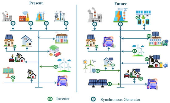
Figure 1.
An illustration of fast-growing trend toward the IBRs integration.
In addition, conventional power systems mostly rely on synchronous machines, having a rigid synchronization with each other, to support the system voltage and frequency stability by means of exciters and governor control, respectively. During various grid disturbances, such as load variation and faults, the frequency of the conventional power system is maintained within permissible limits through the mechanical inertia of the machine. In contrast, the IBRs connected to the power grid follow the grid frequency by using phase-locked loop (PLL) controllers, hence the name grid-following (GFL), for maintaining the system operation and stability []. Notably, a GFL-based IBR cannot maintain voltage or frequency during grid disconnection, limiting its ability to operate in stand-alone mode []. Particularly, the voltage control at PCC for GFL converters becomes a challenging issue when they are connected to utility grids by means of high-impedance lines such as offshore wind power plants []. Therefore, the growing penetration of IBRs and the gradual phase-out of conventional generators consequently fragile potential of the power grid to deal with abrupt perturbation. As an alternative, GFM control has been extensively studied and implemented in academia and industry, respectively, as it replicates essential synchronous generator characteristics, including virtual inertia, damping, and droop response [].
Although grid-following (GFL) and grid-forming (GFM) converters differ in control structure and dynamic behavior, their primary objective is the same: to regulate active and reactive power injection while respecting system voltage and current limits []. Their responses during grid disturbances, however, are fundamentally different. As shown in Figure 2, a GFL converter behaves like a current source, maintaining a constant current phasor Ig, which results in variations in the converter output voltage phasor Vc (Figure 2a, right). In contrast, a GFM converter operates as a voltage source behind a low series impedance, keeping its voltage phasor constant while the current phasor varies (Figure 2b, right). The magnitude of these variations depends on the disturbance characteristics and grid stiffness, highlighting the importance of converter type for maintaining stability under weak-grid or sudden perturbation scenarios [].

Figure 2.
Simplified representation of power converters control: (a,b) (left) GFL and GFM control; (a,b) (right) GFL and GFM (phasor).
Various studies have investigated droop-based grid-forming control strategies, each addressing specific aspects of system performance, as summarized in Table 1. Classification approaches have been proposed to distinguish control variants based on PLL integration [] and control loop architecture [], while advanced controllers including fractional-order PI [] and power angle-frequency droop [] have been developed to enhance transient response and stability margins. Modeling techniques for large-scale system analysis [] and impedance-based stability assessment [] have also been established. However, these studies primarily focus on steady-state operation or specific fault scenarios without comprehensively addressing the dynamic performance during mode transitions under varying grid impedances. Additional research has examined harmonic interactions [], feeder impedance compensation [], global stability conditions [], and oscillation suppression in hybrid systems []. Comparative analyses between different control approaches [] have highlighted trade-offs in implementation complexity and dynamic performance.
Beyond droop control strategies, the broader context of grid-connected converter performance under varying grid strengths has been extensively studied. In [], the effects of grid strength and impedance parameters on the power transfer capability of grid-connected converters employing the GFL approach are examined, showing that a high short-circuit ratio (SCR) coupled with a low R/X ratio enhance the system’s power transfer capability. Similarly, ref. [] provides a thorough insight into the performance of GFM IBR under various grid operating conditions. The study mainly focuses on the comparison of various existing GFM control approaches with attention to large-signal stability. However, the authors do not consider the effect of high IBR penetration on system stability. Moreover, research in [] provides an assessment study on grid strength in terms of small-signal stability for 100% IBR with GFL and GFM control. Authors in [] provide a comparative study of single-loop and multi-loop droop control GFM approach and their impact on the dynamic performance of the converter. Another research in [] analyzes the performance of droop and oscillator-based GFM converters in response to terminal voltage, transient stability, and harmonics compensation in the converter’s output current. It is revealed that droop control is superior in harmonic current suppression due to the definite time-scale separation of control loops, while the oscillator-based GFM approach is easy to implement due to fewer number of sensors requirements. However, these works mostly focused on either the GFL approach or virtual synchronous generator (VSG)-based GFM control. Moreover, most of the authors in the reported research works focused on droop control for GFM converters for different objectives such as seamless transition, damping oscillations, and load sharing between parallel converters.
Despite these valuable contributions, the existing literature lacks a systematic investigation of droop-based GFM inverter behavior during islanded-to-grid-connected transitions combined with short transient faults (50–500 μs) and varying grid impedance characteristics (SCR and X/R ratios), particularly under nonlinear loading conditions. The impact of grid strength and its characteristics on the dynamic performance of droop-based GFM converters needs to be further investigated to evaluate the performance under various grid disturbances, particularly changes in SCR and X/R ratio, short transient faults, mode transitions, and nonlinear load conditions.
To address this gap in knowledge, this paper models a grid-connected converter employing droop-based GFM control as a case study. Comprehensive guidelines for developing various control loops of the proposed converter are provided. Then, the dynamic performance of the droop-controlled GFM inverter is evaluated under distinct grid operating conditions with varying impedances, including islanded-to-grid-connected transitions, transient faults of 50–500 μs duration, and operation under nonlinear loads with varying SCR and X/R ratios.
The main contributions of this work are summarized as follows.
- A comprehensive modeling and control framework for droop-based grid-forming converters is developed with detailed implementation guidelines for all control loops.
- Dynamic performance of the proposed GFM converter is thoroughly investigated and discussed during distinct cases of grid strength and the mode of operation (i.e., islanded or grid-connected) through MATLAB/Simulink (R2024-b) simulations.
- The inverter’s performance during short transient faults (50–500 μs) and under nonlinear loads is analyzed, including voltage and current responses and total harmonic distortion (THD).
The rest of this paper is organized as follows: Section 2 presents the configuration and control design of the droop-based GFM converter. Section 3 discusses the simulation results and performance evaluation under various operating conditions. Finally, Section 4 concludes the paper with key findings and future research directions.

Table 1.
Comparative summary of droop-based GFM control research: analysis methods and identified gaps.
Table 1.
Comparative summary of droop-based GFM control research: analysis methods and identified gaps.
| Reference | Control Approach | Analysis Method | Grid Condition | Fault/Disturbance | Key Metric | Key Limitations |
|---|---|---|---|---|---|---|
| [] | PLL-integrated droop | Time-domain simulation, pole map | Single-terminal HVDC | Ideal DC Bus | Power regulation accuracy, virtual inertia | No mode transition, fixed impedance |
| [] | Single/multi-loop droop | Small-signal stability analysis | Microgrid | N/A | Stability boundary, damping ratio | Steady-state stability, no transient faults |
| [] | FOPI droop | Monte Carlo optimization, ISE/ISCO | Transmission system | Unbalanced load, line fault | Error reduction (65–83%) | Specific faults, no impedance variation |
| [] | Basic (P-f, Q-V) droop | Positive-sequence EMT comparison | Transmission (IEEE 39-bus) | Three-phase fault | Computational efficiency, accuracy | Transmission-level focus, no μs faults |
| [] | Droop with harmonic control | Multiple-harmonic DPM, eigenvalue | Two-inverters network | DC offset, 2nd harmonic, unbalance | Eigenvalue migration, damping | No impedance variation study |
| [] | Robust V-I droop | MIMO stability, disturbance observer | Islanded microgrid | Feeder impedance uncertainty, nonlinear load | PCC voltage THD, power-sharing error | No rapid impedance change |
| [] | Power angle-frequency droop | Transient stability, HIL validation | Grid-connected inverter | Voltage dip (20–80%) | Stability margin, recovery time | No X/R ratio impact, no mode transition |
| [] | Complex droop (dVOC) | Lyapunov stability, full-order dynamics | Grid-connected inverter | Grid interruption | ROA, transient stability conditions | Theoretical focus, no SCR analysis |
| [] | Droop with AIM | Impedance modeling (αβ-frame) | Grid-connected inverter | Load change, grid impedance variation | Frequency coupling bandwidth | Steady-state validation only |
| [] | Adaptive droop | ISCR-based stability, eigenvalue | Hybrid GFM-GFL | Wideband oscillation | Oscillation damping, frequency range | No short-duration faults |
| This Work | GFM Droop | Time domain, THD, mode transition | Islanded/grid-connected | Transient faults, nonlinear load, impedance variation | Voltage/current THD, frequency deviation, recovery time | Comprehensive dynamic analysis addressing identified gaps |
2. Configuration and Control of Proposed GFM Converter
2.1. Description of the System Under Study
A single-line diagram of the electrical network considered in this work is shown in Figure 3. The system consists of a grid-forming (GFM) voltage source converter supplying a local PQ load rated at 2 kW and 2 kVAr, as well as a distributed PQ load of the same rating connected through a low-voltage distribution feeder. These loads are interfaced with a 230 V, 50 Hz utility grid. The converter employs an LC output filter represented by Lf and Cf, which shapes the inverter voltage and attenuates switching harmonics. The utility grid is modeled as an ideal voltage vg in series with an equivalent impedance (Zg = Rg + jXg). The AC bus voltage is expressed by vpcc which is the point of common coupling (PCC), and vc represents the converter output voltage. The grid and inverter output currents are represented by ig and io, respectively.

Figure 3.
Single-line diagram of the power system under study.
The operating mode of the converter depends on the status of switch S. When switch S is open, the inverter operates in stand-alone (islanded) mode, supplying power solely to the local load. In this situation, both the frequency and the magnitude of the PCC voltage are dictated by the GFM control strategy and the dynamic characteristics of the connected load. Conversely, when switch S is closed, the system transitions to grid-connected mode, and the converter output voltage vc must match the grid voltage vg in magnitude, phase, and frequency.
During severe grid disturbances, such as voltage sags, faults, or instability events, it is common practice to intentionally disconnect the VSC from the grid to prevent excessive currents and ensure uninterrupted operation for the local load. Once the grid returns to normal conditions, the magnitude and frequency of vg and vc may differ significantly. If switch S is closed under these mismatched conditions, the resulting transient power exchange may lead to substantial inrush currents and trigger converter overcurrent protection. To prevent such undesirable events, IEEE Std. 1547-2018 [] mandates strict synchronization limits for voltage magnitude, frequency deviation, and phase angle difference before reconnection of distributed energy resources. Thus, prior to reclosing S, the converter voltage vc must be synchronized with the grid voltage vg to ensure a smooth transition back to grid-connected operation.
The overall structure of the adopted control framework is illustrated in Figure 4. The hierarchical control architecture includes primary droop control, inner voltage and current regulation loops, a secondary control layer that restores deviations in voltage amplitude and frequency, and a tertiary control layer that determines real and reactive power exchange with the grid. The control scheme is implemented in the αβ reference frame to facilitate the use of proportional–resonant (PR) controllers, which provide infinite gain at the fundamental frequency and ensure zero steady-state tracking error [].
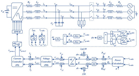
Figure 4.
Overall control structure of the proposed droop-based GFM inverter.
2.2. Power Controller
The vαβ and iαβ components are used to obtain the instantaneous values of active and reactive power, p and q, as expressed in (1). To eliminate the high frequency ripples, the obtained values of p and q are passed through low pass filters with cutoff frequency ωc, yielding the average values and as given in (2):
Here, and denote the capacitor voltage and output current, while p and q represent the instantaneous active and reactive power, respectively.
2.3. Droop Controller
In this work, a dynamic-compensated droop-based primary outer control is employed to determine the reference values for the phase angle θ and voltage magnitude V. These references, obtained from the outer loop, subsequently fed to the inner voltage and current control loops which synthesize the converter’s terminal voltage reference. While conventional droop control relies solely on proportional relationships in the active power–frequency (P-f) and reactive power–voltage (Q-V) characteristics, the adopted scheme enhances this structure by incorporating derivative terms to improve transient response and oscillation damping, and an integral term in the Q-V loop to eliminate steady-state reactive power errors. This modification enables more accurate voltage and frequency regulation under rapid power variations and strengthens stability in weak-grid scenario.
The enhanced P-f and Q-V droop characteristics are expressed in (3) and (4), respectively. The corresponding block diagram of the adopted outer control loop is shown in Figure 5. In the proposed structure, the P-f droop determines the phase angle deviation, while the Q-V droop governs the amplitude of the terminal voltage, both benefiting from the added dynamic compensation.
where ω and V are the measured angular frequency and amplitude of the inverter output voltage, Vref, and ωref are the rated angular frequency and output voltage, and are the measured active and reactive power obtained from the power calculation block as described in Equation (7), Pref and Qref are the active and reactive power references, respectively.
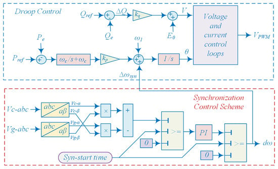
Figure 5.
Control block diagram of GFM converter with synchronization control loop.
2.4. Synchronization Control Loop
The control block diagram of the synchronization control process adopted in this research is depicted in Figure 5, enclosed in the red lines. This control mechanism is activated at t = 1 s to synchronize the converter voltage vc with the grid voltage vg before closing the switch S to connect to the grid. It can be noted from Figure 5 that the phase difference between vc and vg is obtained by cross product of such vectors and comparing their result with zero, and the error is applied to the PI controller. The output of PI controller, ∆ω, is added to the active power control loop to determine the reference angular frequency ω of the voltage. Therefore, the phase angle θc of the converter voltage is equal to the phase angle θg of grid voltage, in steady-state operation, after synchronization is achieved.
During the synchronization process, prior to switch S closing, the control law of the active power loop can be drawn as
Here, and are the magnitude of grid and converter’s output voltage in alpha–beta reference frame, respectively. The error between two voltage phases is fed to the PI controller to reduce the phase error and provide a control signal ∆ω to the converter to control its phase and frequency. The proportional and integral gains of the PI controller are represented by kps and kis (kps = 5 × 10⁻⁵, kis = 0.001), respectively.
It is important to note that the synchronization control loop is enabled only during the synchronization process, and it is disabled as soon as the synchronization is fulfilled. The synchronization process is obtained by using the alpha–beta components of the grid and the converter voltage variables vc and vg. Therefore, the synchronization process is fulfilled when (6) is satisfied.
The effectiveness of the adopted synchronization scheme can be observed from the simulation waveform in Figure 6. Before t = 1 s, the VSC operates in stand-alone mode to supply the power to the local PQ load. However, the output frequency of the converter deviates from the grid frequency, which can be observed from the phase angle difference between vc and vg. To synchronize the two voltages, the synchronization scheme is activated at t = 1 s which regulates such phase difference to zero around t = 1.5 s.
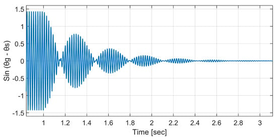
Figure 6.
Phase difference between Vg and Vc during transition from IS to GC mode.
2.5. Inner Voltage and Current Control Loop
The inner control loop consists of two cascaded voltage and current control loops as presented in Figure 7, which are responsible for controlling the converter terminal voltage and the reference current injected by the converter, respectively. The two cascaded controllers are represented by a block diagram as shown in Figure 8, where the voltage control loop incorporates the PR controller while the current control loop uses the PI controller. A detailed model of the internal control loops has been presented by [,]. The closed-loop transfer function of the current loop is given as follows:
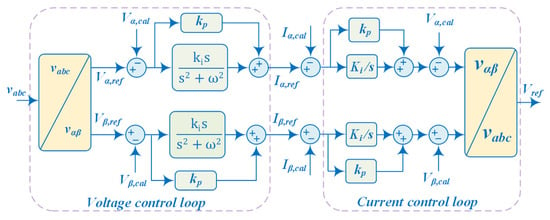
Figure 7.
Inner voltage current control loops.
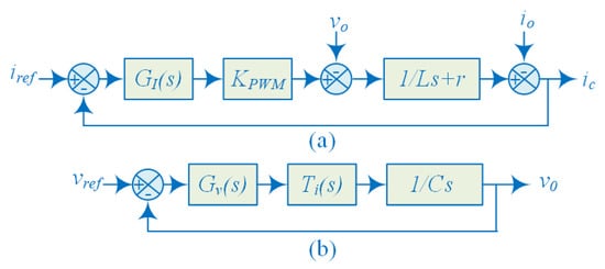
Figure 8.
Block diagram of inner loops: (a) current control loop; (b) voltage control loop.
If ,
Taking the switching frequency of 10 kHz, the cutoff frequency ωc of the current loop is set to Then, the value is calculated based on the bandwidth ().
Similarly, the closed-loop transfer function of voltage control, as shown in Figure 8, is given as follows:
Putting , Equation (10) can be modified as follows:
where ; ; ; ; ; ; .
Bode plots of the designed current and voltage control loops are reported in Figure 9. It is worth noting that the current loop exhibits a bandwidth of approximately 4 kHz with a phase margin of about 75°, ensuring fast and stable current regulation. In contrast, the voltage loop has a bandwidth of around 800 Hz with a phase margin of approximately 50°. This design ensures that the current loop bandwidth is significantly higher than the voltage loop bandwidth (about five times larger), which is a standard requirement for cascaded control structures. The sufficient gain and phase margins in both loops confirm the robustness and stability of the controller design.

Figure 9.
Bode plots of inner loops: (a) current control loop; (b) voltage control loop.
2.6. Secondary Control
The secondary control aims to compensate for the frequency and voltage deviations introduced by the droop control due to abrupt changes in load or power generation. Therefore, the secondary control adjusts the frequency and voltage deviations within the permissible limit defined by a particular grid code. The adopted voltage and frequency restoration compensator can be derived as follows []:
where , , , and are the control parameters of the secondary control compensator, it is worth noting that is the synchronization term which is equal to zero in the absence of grid.
2.7. Tertiary Control
The tertiary control is adopted to control the active and reactive power flow between the GFM converter and utility grid by measuring the Pe and Qe and comparing them with their reference values Pref and Qref, as expressed in (14) and (15).
The set point of frequency and voltage amplitude is generated by tertiary when the converter is in On-grid mode, while the control remains inactive in Off-grid mode, and these reference values in the secondary are selected appropriately.
3. Simulation Results and Discussion
To demonstrate the effectiveness of the adopted control scheme shown in Figure 3 and Figure 4, a comprehensive simulation model of a 10 kVA grid-connected inverter is developed in Matlab/Simulink environment. Detailed simulations are performed to systematically evaluate the dynamic performance of the droop-based GFM control under diverse operating conditions. The key system and control parameters are listed in Table 2. Initially, a strong power grid with SCR = 7 is considered to establish baseline performance in both islanded and grid-connected modes. Step changes in active and reactive power references are applied to assess reference-tracking capability and transient response. To evaluate fault ride-through performance, three-phase to ground faults with durations of 50 µs, 100 µs, 350 µs, and 500 µs are applied at the point of common coupling. Power quality assessment under nonlinear loading conditions is conducted using a three-phase diode rectifier with resistive–inductive load. Subsequently, to investigate performance sensitivity to grid strength, extensive simulations are performed across varying SCRs (3, 7) and X/R ratios (1, 3, 7) during islanded-to-grid-connected mode transitions.

Table 2.
Parameters of the system under study.
3.1. Performance Evaluation in Islanded and Grid-Connected Mode of Operation
Simulations are performed in this section to evaluate the performance of the adopted droop-based GFM converter in islanded (IS) and grid-connected (GC) operation modes. The simulation waveform of the grid voltage and current, converter output voltage and current, active and reactive power, frequency, and synchronization error are presented in Figure 10 and Figure 11. It can be noted from the figures that initially the inverter supplies a local load of 2 kW and 1 kVAr while operating in islanded mode. A synchronization control scheme presented in [] is adopted to synchronize the grid and converter voltage before closing the switch S to integrate the converter into the grid. It is obvious that before t = 1 s, the frequency of the grid and converter voltages deviated from each other, which can be realized from the synchronization error reported in Figure 11 (right, a). The synchronization scheme is activated at t = 1 s to synchronize the converter voltage with grid voltage, where the synchronization error is regulated to be less than ±5V at around t = 1.5 s.
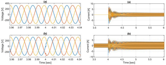
Figure 10.
System response during transition from IS to GC mode: (a,b) (left) grid voltage and converter output voltage; (a,b) (right) grid current and converter output current.
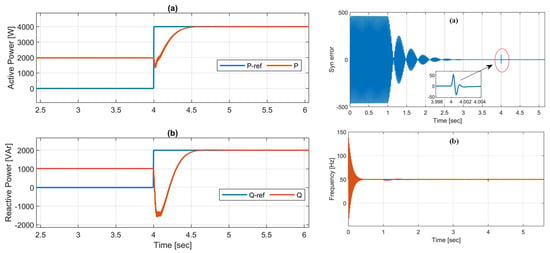
Figure 11.
System response during transition from IS to GC mode: (a,b) (left) active and reactive power; (a,b) (right) synchronization error and frequency measured at PCC.
Once the synchronization is ensured, the grid with a 2 kW and 1 kVAr PQ distributed load connects by closing the switch at t = 4 s. It can be seen from the active and reactive power plots that after t = 4 s the converter supplies 4 kW and 2 kVAr to the two PQ loads (2 kW and 1 kVAr each). The simulations reveal that the system works well, where the converter has the competence to synchronize with the grid and maintain a constant output voltage in either mode of operation, i.e., islanded and grid-connected. The grid and converter voltage are balanced and constant in magnitude. Moreover, the simulation results show that the adopted GFM control algorithm works effectively to adjust voltage and frequency according to the changes in active and reactive power references.
3.2. Change in Power Set Point
In this part of the simulations, the response of the implemented control algorithm in tracking the reference signals has been evaluated by applying a step change in the active and reactive power set points. At t = 10 s, a sudden increment of 2 kW and 1 kVAr happens in the generation; therefore, the active power of generation rises from 4 kW to 6 kW, and reactive power is 3 kVAr, where the surplus power (2 kW and 1 kVAr) is injected into the grid. The active and reactive power outputs of the GFM converter are depicted in Figure 12. It is worth noting that the outer power control loop has a strong ability to trace the reference signals during transients. Moreover, the grid voltage under αβ axis and frequency measured at PCC for the proposed control algorithm are presented in Figure 12 and Figure 13. It can be observed from the figures that the adopted GFM control can work well, and the voltage loop can track the given αβ references.
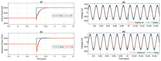
Figure 12.
System response during a step change in power: (a,b) (left) active power and reactive power; (a,b) (right) reference and measured voltages in alpha–beta frame.
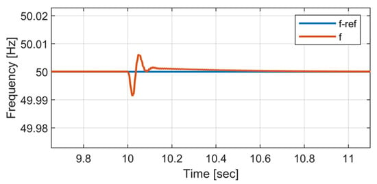
Figure 13.
System frequency measured at PCC.
3.3. Power Quality Analysis with Nonlinear Load
To evaluate the power quality performance of the proposed grid-connected inverter system under nonlinear impedance conditions, a detailed harmonic analysis was carried out for both currents and voltages at key system nodes—namely, the grid side, inverter output, and load terminals as shown in Figure 14. A 2-kW nonlinear load (diode rectifier supplying a resistive load) was connected at the PCC. This configuration caused the load current to exhibit significant waveform distortion due to the rectification process, thereby injecting current harmonics into the system.
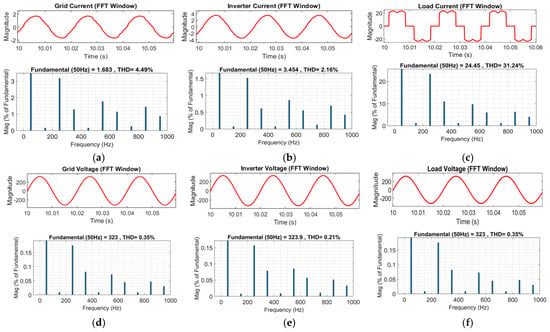
Figure 14.
FFT-based THD analysis of grid-connected inverter under nonlinear load: (a) grid current, (b) inverter output current, (c) load current, (d) grid voltage, (e) inverter output voltage, and (f) load voltage.
The Fast Fourier Transform (FFT) analysis was performed to quantify the total harmonic distortion (THD) in the time-domain waveforms of the grid current, inverter output current, and load current, as well as their corresponding voltages.
- The load current showed the highest THD (≈31%), confirming the highly nonlinear nature of the connected load.
- The inverter output current exhibited a considerably lower THD (≈2%), indicating that the inverter’s control and filter effectively mitigated most harmonic components before feeding into the grid.
- The grid current maintained a moderate THD level (≈4%), demonstrating that the inverter successfully prevented significant harmonic injection into the grid.
Similarly, voltage waveforms at all three nodes were analyzed to assess the inverter’s impact on voltage quality. The grid voltage, inverter output voltage, and load voltage all maintained THD levels below 0.5%, well within IEEE Std. 519-2014 limits [], indicating that the inverter effectively regulated its terminal voltage and did not distort the grid voltage.
Moreover, Figure 15 illustrates the variation in THD with load from 1 kW to 6 kW. As the load increases, the THD of inverter and grid currents rises due to higher harmonic injection from the nonlinear load, whereas the load current THD remains nearly constant. The voltage THD remains below 1% for all cases, confirming compliance with IEEE 519 standards.
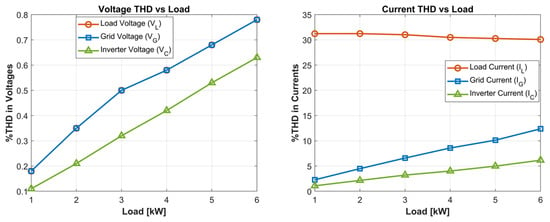
Figure 15.
Variation in voltage and current THD with variation in nonlinear load.
Overall, the results confirm that the proposed inverter system provides excellent harmonic performance, even under nonlinear loading, by maintaining both current and voltage THD well within acceptable limits. This validates the inverter’s capability for grid-friendly operation and harmonic suppression, which are critical for modern renewable and power-electronic-dominated grids.
3.4. Change in SCR and X/R Ratio
The impedance of the grid and connecting lines has a significant impact on the dynamic performance of grid-connected converters. The strength of the grid is usually measured by SCR which is inversely proportional to the grid impedance as described []:
where Psc represents the grid short-circuit power; PDC-rated is the rated power of the connected converter; Vg and Zg are grid voltage and impedance, respectively. It is worth noting that the higher the grid impedance, the lower the SCR value and the less the grid strength, and vice versa. Moreover, with a given SCR value, the X/R ratio is another important factor to be considered in the converter performance.
Voltage source converters connected to weak power grids are highly sensitive to changes in active and reactive power injection and/or absorption. In a particular case of a weak grid with severe disturbance, the converter may lose synchronization and disconnect from the grid. In this subsection, the performance of the proposed converter is evaluated for various cases of grid strength, as detailed in Table 3, during the transition from islanded to grid-connected mode of operation.

Table 3.
Summary of the selected grid and line impedance parameters.
In the first case, simulation results are obtained for the strong grid with SCR = 7 and the X/R ratio is selected as 1, 3, and 7. The key performance indicators during the transition from islanded to grid-connected mode, at t = 4 s, are shown in Figure 16. As shown in the figures, in predominantly resistive networks (X/R = 1), active power flow follows , creating stronger P-V coupling that manifests as larger voltage fluctuations in subplot c (≈309 V minimum) and more pronounced active power oscillations in subplot a. Conversely, in inductive networks (X/R = 7), the relationship and predominates, resulting in improved voltage stability (≈311 V minimum) and smoother power transitions. The reactive power transients (subplot b) exhibit approximately 3500 VAr peak-to-peak variation, with X/R = 7 showing superior damping coefficient due to the natural energy storage characteristics of inductive networks. The frequency deviation in subplot g (reaching 50.08 Hz), where network impedance affects the synchronizing coefficient, resulting in smaller frequency excursions for higher X/R ratios. The converter current in (subplot f) demonstrates the relationship I ≈ P/V, with X/R ratio influencing the power–angle relationship and consequently the transient current characteristics.
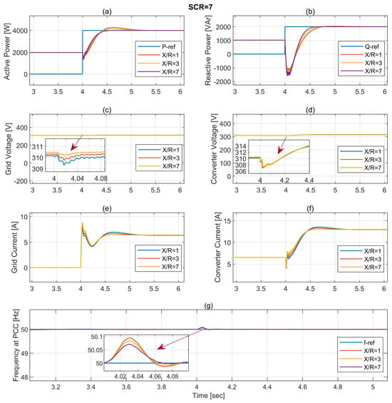
Figure 16.
System response during transition with respect to SCR = 7 and X/R = 1, 3, and 7: (a) active power; (b) reactive power; (c) grid voltage; (d) converter voltage; (e) grid current; (f) converter output current; (g) frequency at PCC.
Similarly, in the second case, simulation results are obtained for the weak grid with SCR = 3, and the X/R ratio is selected as 1, 3, and 7. As shown in Figure 17, the reduced short-circuit ratio significantly impacts system dynamics across all metrics. Active power transition (subplot a) exhibits a more pronounced initial power dip compared to the SCR = 7 case, with P-V coupling producing more distinctive differences between X/R ratios. The reactive power response (subplot b) shows deeper negative excursions (exceeding 500 VAr) and slower recovery, validating the mathematical relationship where lower SCR amplifies voltage sensitivity. Most notably, grid and converter voltage profiles (subplots c and d) reveal substantially deeper voltage sags (reaching approximately 304 V for X/R = 1 versus 308 V for X/R = 7), representing a ~2% deeper voltage depression than in the stronger grid case. This aligns with voltage sensitivity factor theory, where ∂V/∂Q increases with decreasing SCR. The transient grid current (subplot e) exhibits more pronounced oscillatory behavior with higher peak currents, while converter current dynamics (subplot f) demonstrate slower convergence to steady state. The frequency excursions (subplot g) reach approximately 50.1 Hz—slightly higher than in the SCR = 7 case, where lower SCR effectively reduces the system’s ability to resist frequency deviations.
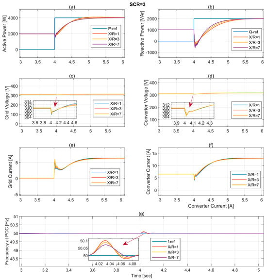
Figure 17.
System response during transition with respect to SCR = 3 and X/R = 1, 3, and 7: (a) active power; (b) reactive power; (c) grid voltage; (d) converter voltage; (e) grid current; (f) converter output current; (g) frequency at PCC.
The key performance indicators observed in various cases of grid strength and its impedance characteristics are summarized in Table 4. To sum up, the weaker grid case (SCR = 3) consistently demonstrates more pronounced transient behavior across all measured parameters: deeper voltage sags (approximately 4% deeper than with SCR = 7), larger reactive power excursions, more significant frequency deviations, and prolonged settling times. The impact of X/R ratio variations becomes more consequential in weaker grids, with X/R = 1 exhibiting substantially degraded performance compared to X/R = 7, particularly in voltage recovery and reactive power stabilization.

Table 4.
Summary of key performance indicators under varying grid SCR and X/R conditions.
To analyze the impact of grid impedance variations on the small-signal stability of the droop-based GFM inverter, a linearized state-space model was derived from the active power–frequency and reactive power–voltage droop equations. The state vector was defined as
where is the power angle, is the angular frequency deviation, V is magnitude of the terminal voltage, and is the integral state associated with the Q-V control loop. The resulting small-signal model can be expressed as follows:
The grid impedance was parameterized by the short-circuit ratio (SCR) and X/R ratio, such that both grid strength and impedance characteristics are reflected in the eigenvalue analysis.
Figure 18 shows the eigenvalue trajectories for two representative grid strengths (SCR = 7 and SCR = 3) under a continuous sweep of X/R from 1 to 7. For SCR = 7, eigenvalues remain well-damped in the left half-plane, confirming fast dynamics and robust stability. In contrast, for SCR = 3, eigenvalues shift closer to the imaginary axis as X/R increases, indicating weaker damping and lightly oscillatory modes. These results confirm that both grid strength and impedance characteristics significantly affect the dynamic performance of droop-controlled GFM inverters.

Figure 18.
Eigenvalue trajectories of the system under varying grid impedances and X/R ratio.
Overall, all eigenvalues remain in the left half-plane across the investigated range of SCR and X/R, confirming that the droop-controlled GFM inverter remains stable under all considered grid conditions, with stability margins that depend on grid strength and impedance ratio.
3.5. Performance of the System Under Transient Faults
The dynamic response of the inverter under three-phase fault conditions with varying durations (50 µs, 100 µs, 350 µs, and 500 µs) is presented in Figure 19, where the fault is applied at t = 10 s at the PCC. The results reveal a strong correlation between fault duration and the severity of system disturbances. Notably, the 50 µs fault produces negligible impact on all monitored parameters, with voltage, current, active power, reactive power, and frequency maintaining near steady-state values throughout the fault event. This suggests that the inverter control system response time is significantly longer than 50 µs, effectively filtering out such ultra-short transients. In contrast, as fault duration increases to 100 µs and beyond, the inverter begins to exhibit measurable responses. For the 100 µs fault, mild voltage sag and current spike are observed, though recovery is rapid and well-damped. The most significant disturbances occur during the 350 µs and 500 µs faults, where the PCC voltage drops sharply to approximately 323–324 V from the nominal 328 V, accompanied by substantial current spikes reaching up to 10 A (compared to 7.5 A nominal). Active power exhibits sharp spikes exceeding 2300 W followed by temporary dips before recovery, while reactive power surges to approximately 2100 VAR, demonstrating the inverter’s grid-support capability during voltage disturbances. The frequency response shows pronounced oscillations of ±1.5 Hz, reflecting the power–frequency coupling inherent in droop-based control. Post-fault recovery demonstrates damped oscillatory behavior with stabilization times proportional to fault duration, ranging from 100 ms for the 100 µs fault to 400 ms for the 500 µs fault, while maintaining synchronization throughout all events. These results indicate that fault duration acts as a critical threshold parameter, with faults below 50–100 µs being effectively transparent to the control system, validating the robustness of the droop-based grid-forming control for practical grid applications.
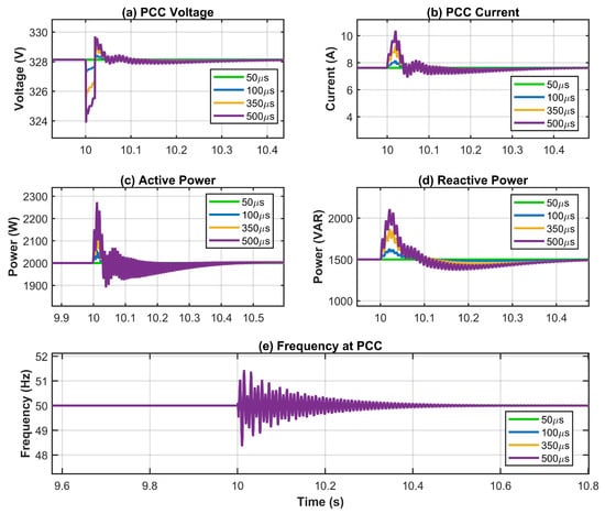
Figure 19.
Performance of the system under three-phase short-circuit fault with varying duration (50–500 µs).
4. Conclusions
The fast-growing penetration of renewable energy sources in modern power systems affects grid strength and presents significant stability challenges. This work provides important insights into droop-controlled grid-forming (GFM) converters and the impact of grid impedance (SCR) and its characteristics (X/R ratio) on the dynamic performance of inverter-based power systems. Following an extensive literature review that identified critical research gaps in existing GFM control studies, a detailed case study is conducted to evaluate the dynamic performance of the droop-based GFM converter under diverse and challenging operating conditions, including varying grid impedances, mode transitions, transient faults, and nonlinear loads.
The study reveals that the proposed GFM approach exhibits superior reference-tracking capabilities during sudden changes in active and reactive power set points and maintains stable voltage and frequency in both grid-connected and autonomous modes. Simulation results quantify the influence of grid strength (SCR) and impedance angle (X/R ratio) on system performance: scenarios with SCR = 3 show greater deviations in all KPIs compared to SCR = 7 cases, while higher X/R ratios consistently improve performance metrics—reducing voltage sags by up to 2.3%, decreasing frequency deviations by approximately 25%, and accelerating settling times by 15–22%. These improvements are particularly critical in weak-grid conditions.
To complement the dynamic performance analysis, a linearized small-signal stability study with eigenvalue trajectories and Bode plots of the inner voltage and current loops have been included, demonstrating system stability and providing guidance for controller bandwidth selection. Transient fault analysis under three-phase to ground faults (50–500 µs) reveals critical threshold behavior: faults below 50–100 µs produce negligible impact, while longer durations trigger proportional responses with voltage sags reaching 5 V, current spikes up to 10 A, and power transients exceeding 15%. Recovery times range from 100 ms (100 µs fault) to 400 ms (500 µs fault), with the droop control maintaining synchronization throughout all events, demonstrating robust fault ride-through capability.
Performance under nonlinear loads (three-phase diode rectifier) shows voltage THD below 1% and current THD below 5%, remaining within IEEE 519 limits despite harmonic injections. These findings offer valuable design guidelines for inverter control systems in evolving power networks, especially in weak-grid applications, where accurate impedance characterization is essential for stable operation. The robustness and scalability of the proposed scheme for large-scale microgrids, supported by detailed stability analysis, will be explored in future studies.
Author Contributions
Conceptualization, M.U. and Y.G.; methodology, M.U. and Y.G.; software, M.U.; validation, M.U., M.A.B. and Y.G.; formal analysis, M.U.; investigation, M.U. and Y.G.; resources, Y.G. and J.C.V.; writing—original draft preparation, M.U.; writing—review and editing, M.U., Y.G. and M.A.B.; visualization, M.U. and J.C.V.; supervision, Y.G., J.C.V. and J.M.G.; project administration, Y.G. and J.C.V.; funding acquisition, Y.G. and J.C.V. All authors have read and agreed to the published version of the manuscript.
Funding
This work was supported by LastWind project (Granted by Danish Ministry for Foreign Affairs and supported by Danida Fellowship Centre under grant 23-M01-AAU) and Higher Education Commission (HEC) Pakistan.
Institutional Review Board Statement
Not applicable.
Informed Consent Statement
Not applicable.
Data Availability Statement
The original contributions presented in this study are included in the article. Further inquiries can be directed to the corresponding authors.
Acknowledgments
The authors would like to thank the administrative and technical staff at Aalborg University and the partner institutions for their valuable assistance during the development and execution of this research. The authors also acknowledge the helpful discussions and coordination support provided by the LastWind project team. Additionally, we appreciate the computational resources and technical facilities made available during the study.
Conflicts of Interest
Author Manuel A. Barrios was employed by the company sonnen Inc. The remaining authors declare that the research was conducted in the absence of any commercial or financial relationships that could be construed as a potential conflict of interest.
References
- Ravada, B.R.; Tummuru, N.R.; Ande, B.N.L. Photovoltaic-Wind and Hybrid Energy Storage Integrated Multisource Converter Configuration-Based Grid-Interactive Microgrid. IEEE Trans. Ind. Electron. 2021, 68, 4004–4013. [Google Scholar] [CrossRef]
- Jovcic, D. Phase Locked Loop System for FACTS. IEEE Trans. Power Syst. 2003, 18, 1116–1124. [Google Scholar] [CrossRef]
- Montero-Robina, P.; Rouzbehi, K.; Gordillo, F.; Pou, J. Grid-Following Voltage Source Converters: Basic Schemes and Current Control Techniques to Operate with Unbalanced Voltage Conditions. IEEE Open J. Ind. Electron. Soc. 2021, 2, 528–544. [Google Scholar] [CrossRef]
- Ullah, M.; Guan, Y.; Vasquez, J.C.; Guerrero, J.M. Analysis of Power Quality Improvement Techniques Applied to Grid-Connected Wind Power Plants. In Proceedings of the 2024 IEEE 15th International Symposium on Power Electronics for Distributed Generation Systems (PEDG), Luxembourg, 23–26 June 2024; pp. 1–6. [Google Scholar]
- Rosso, R.; Wang, X.; Liserre, M.; Lu, X.; Engelken, S. Grid-Forming Converters: Control Approaches, Grid-Synchronization, and Future Trends—A Review. IEEE Open J. Ind. Appl. 2021, 2, 93–109. [Google Scholar] [CrossRef]
- Ullah, M.; Guan, Y.; Yu, Y.; Chaudhary, S.K.; Vasquez, J.C.; Guerrero, J.M. Dynamic Performance and Power Quality of Large-Scale Wind Power Plants: A Review on Challenges, Evolving Grid Code, and Proposed Solutions. IEEE Open J. Power Electron. 2025, 6, 1148–1173. [Google Scholar] [CrossRef]
- Rokrok, E.; Qoria, T.; Bruyere, A.; Francois, B.; Guillaud, X. Classification and Dynamic Assessment of Droop-Based Grid-Forming Control Schemes: Application in HVDC Systems. Electr. Power Syst. Res. 2020, 189, 106765. [Google Scholar] [CrossRef]
- Du, W.; Chen, Z.; Schneider, K.P.; Lasseter, R.H.; Pushpak Nandanoori, S.; Tuffner, F.K.; Kundu, S. A Comparative Study of Two Widely Used Grid-Forming Droop Controls on Microgrid Small-Signal Stability. IEEE J. Emerg. Sel. Top. Power Electron. 2020, 8, 963–975. [Google Scholar] [CrossRef]
- Chiza, L.L.; Benítez, D.; Aguilar, R.; Camacho, O. Droop Control in Grid-Forming Converters Using a Fractional-Order PI Controller: A Power System Transient Analysis. Results Control Optim. 2025, 18, 100517. [Google Scholar] [CrossRef]
- Awal, M.A.; Yu, H.; Lukic, S.; Husain, I. Droop and Oscillator Based Grid-Forming Converter Controls: A Comparative Performance Analysis. Front. Energy Res. 2020, 8, 168. [Google Scholar] [CrossRef]
- Du, W.; Nguyen, Q.H.; Wang, S.; Kim, J.; Liu, Y.; Zhu, S.; Tuffner, F.K.; Huang, Z. Positive-Sequence Modeling of Droop-Controlled Grid-Forming Inverters for Transient Stability Simulation of Transmission Systems. IEEE Trans. Power Deliv. 2024, 39, 1736–1748. [Google Scholar] [CrossRef]
- Pérez-Estévez, D.; Ríos-Castro, D.; Marino Fernández-Abraldes, P.; Pinto, J.G.; Afonso, J.L.; Doval-Gandoy, J. Asymmetric Impedance Model for Grid-Forming Converters with Droop Control. IEEE Trans. Power Electron. 2025, 40, 12977. [Google Scholar] [CrossRef]
- Hart, P.J.; Goldman, J.; Lasseter, R.H.; Jahns, T.M. Impact of Harmonics and Unbalance on the Dynamics of Grid-Forming, Frequency-Droop-Controlled Inverters. IEEE J. Emerg. Sel. Top. Power Electron. 2020, 8, 976–990. [Google Scholar] [CrossRef]
- Safamehr, H.; Izadi, I.; Ghaisari, J. Robust V-I Droop Control of Grid-Forming Inverters in the Presence of Feeder Impedance Variations and Nonlinear Loads. IEEE Trans. Ind. Electron. 2024, 71, 504–512. [Google Scholar] [CrossRef]
- Erdocia, J.; Urtasun, A.; Marroyo, L. Power Angle–Frequency Droop Control to Enhance Transient Stability of Grid-Forming Inverters Under Voltage Dips. IEEE J. Emerg. Sel. Top. Power Electron. 2023, 11, 3751–3764. [Google Scholar] [CrossRef]
- Qiu, L.; Gu, M.; Chen, Z.; Du, Z.; Zhang, L.; Li, W.; Huang, J.; Fang, J. Oscillation Suppression of Grid-Following Converters by Grid-Forming Converters with Adaptive Droop Control. Energies 2024, 17, 5230. [Google Scholar] [CrossRef]
- He, X.; Huang, L.; Subotic, I.; Haberle, V.; Dorfler, F. Quantitative Stability Conditions for Grid-Forming Converters with Complex Droop Control. IEEE Trans. Power Electron. 2024, 39, 10834–10852. [Google Scholar] [CrossRef]
- Huang, L.; Wu, C.; Zhou, D.; Blaabjerg, F. Impact of Grid Strength and Impedance Characteristics on the Maximum Power Transfer Capability of Grid-Connected Inverters†. Appl. Sci. 2021, 11, 4288. [Google Scholar] [CrossRef]
- Khan, S.A.; Wang, M.; Su, W.; Liu, G.; Chaturvedi, S. Grid-Forming Converters for Stability Issues in Future Power Grids. Energies 2022, 15, 4937. [Google Scholar] [CrossRef]
- Zhao, X.; Flynn, D. Stability Enhancement Strategies for a 100% Grid-Forming and Grid-Following Converter-Based Irish Power System. IET Renew. Power Gener. 2022, 16, 125–138. [Google Scholar] [CrossRef]
- Du, W.; Schneider, K.P.; Lasseter, R.H.; Pushpak, S.; Tuffner, F.K.; Kundu, S. A Comparative Study of Two Widely Used Grid-Forming Droop Controls on Microgrid Small Signal Stability. IEEE J. Emerg. Sel. Top. Power Electron. 2019, 8, 963–975. [Google Scholar] [CrossRef]
- Salem, Q.; Aljarrah, R.; Karimi, M.; Al-Quraan, A. Grid-Forming Inverter Control for Power Sharing in Microgrids Based on P/f and Q/V Droop Characteristics. Sustainability 2023, 15, 11712. [Google Scholar] [CrossRef]
- IEEE Std 1547-2018; (Revision of IEEE Std 1547-2003): IEEE Standard for Interconnection and Interoperability of Distributed Energy Resources with Associated Electric Power Systems Interfaces. IEEE: New York, NY, USA, 2018; ISBN 9781504446396.
- Kuperman, A. Proportional-Resonant Current Controllers Design Based on Desired Transient Performance. IEEE Trans. Power Electron. 2015, 30, 5341–5345. [Google Scholar] [CrossRef]
- Pogaku, N.; Prodanovi’c, M.P.; Green, T.C. Modeling, Analysis and Testing of Autonomous Operation of an Inverter-Based Microgrid. IEEE Trans. Power Electron. 2007, 22, 613–625. [Google Scholar] [CrossRef]
- Astero, P.; Alimardani, A.; Hosseinian, S.H.; Abedi, M. Decentralized Cooperative Control Strategy of Microsources for Stabilizing Autonomous VSC-Based Microgrids. IEEE Trans. Power Syst. 2012, 27, 1949–1959. [Google Scholar] [CrossRef]
- Guerrero, J.M.; Vasquez, J.C.; Matas, J.; De Vicuña, L.G.; Castilla, M. Hierarchical Control of Droop-Controlled AC and DC Microgrids—A General Approach toward Standardization. IEEE Trans. Ind. Electron. 2011, 58, 158–172. [Google Scholar] [CrossRef]
- Li, Y.; Vilathgamuwa, D.M.; Loh, P.C. Design, Analysis, and Real-Time Testing of a Controller for Multibus Microgrid System. IEEE Trans. Power Electron. 2004, 19, 1195–1204. [Google Scholar] [CrossRef]
- IEEE Std. 519-2014; IEEE Recommended Practice and Requirements for Harmonic Control in Electric Power Systems Sponsored by the Transmission and Distribution Committee IEEE Power and Energy Society. IEEE: New York, NY, USA, 2014.
- Liu, Q.; Caldognetto, T.; Buso, S. Stability Analysis and Auto-Tuning of Interlinking Converters Connected to Weak Grids. IEEE Trans. Power Electron. 2019, 34, 9435–9446. [Google Scholar] [CrossRef]
Disclaimer/Publisher’s Note: The statements, opinions and data contained in all publications are solely those of the individual author(s) and contributor(s) and not of MDPI and/or the editor(s). MDPI and/or the editor(s) disclaim responsibility for any injury to people or property resulting from any ideas, methods, instructions or products referred to in the content. |
© 2025 by the authors. Licensee MDPI, Basel, Switzerland. This article is an open access article distributed under the terms and conditions of the Creative Commons Attribution (CC BY) license (https://creativecommons.org/licenses/by/4.0/).