Featured Application
The proposed approach has promising applications in critical scenarios where UAVs must operate efficiently and safely in unstructured environments. For example, it can be utilized in post-disaster search and rescue missions, where drones navigate through rubble-strewn areas to locate survivors while avoiding hazardous obstacles. Additionally, this methodology is valuable for inspecting complex industrial sites, such as offshore oil platforms or wind farms, where geometric constraints and moving obstacles pose significant challenges. By ensuring stable and secure operation in these dynamic conditions, this work contributes to advancing UAV capabilities in mission-critical tasks requiring high precision and reliability.
Abstract
Aerial inspection missions over long distances are guided by planning paths with minimum energy consumption, which generally leads to routes with shorter distances. However, these conditions cannot always be met due to the environment’s geometric constraints, especially in the most unexpected (unsafe, dangerous, and risky) scenarios. The aim of this work is to improve the efficiency, stability, and security of unmanned aerial vehicles (UAVs) during inspection missions in unstructured and unpredictable environments. Traditional path-planning techniques that prioritize minimum energy consumption often lead to routes with shorter distances, but these can be hindered by environmental geometric constraints and risky scenarios. To address this challenge, a new path-planning algorithm is proposed that ensures safe passage through challenging moving locations while respecting the physical limitations of the robot and the shape of narrow passages. The algorithm is combined with a controller design for obstacle avoidance. Experimental results with different motion restrictions are presented, demonstrating the effectiveness of the proposed approach.
1. Introduction
With the rapid evolution of aircraft technologies, computational resources, actuators, sensors, and communication, unmanned aerial vehicles (UAVs) have been increasingly adopted as a suitable tool for several applications []. UAVs are playing important roles not only in urban environments, but also in hazardous areas that are not easily reachable, such as coastal zones, caves, and forests [,,]. In recent years, UAVs have been extensively researched for various applications, including search and rescue operations [,,], monitoring and inspection [,,,,], package delivery [,,,,,], and underground mining [,,]. These applications have garnered attention from academic, scientific, and industrial communities worldwide, requiring the development of autonomous flight technologies that guarantee the safety of the equipment and interaction with the robot’s workspace, which can include static and moving objects.
Autonomous navigation is related to the accurate and safe control of the UAV flight, even in unexpected and risky environments. This requires advanced robot cognition and deliberation for navigation, which is common in inspection tasks [,,]. Most of these tasks involve narrow sections and constrained structures/spaces for the UAVs navigate through. A key challenge lies in generating precise motion planning to ensure the safe inclusion of service UAVs in urban environments. Additionally, motion planning research and development serve academic and educational objectives, including UAV racing and competitions [,,,].
The challenging question is: “How to develop feasible solutions to search for an optimal or quasi-optimal, safe, and time-efficient path between two locations (source and destination) in a 3D map to overcome an obstacle in the scenario?” [,,]. To ensure safe operation, a UAV must possess the ability to perceive its surrounding environment and respond accordingly to avoid collisions with both stationary and moving obstacles. Additionally, it should be capable of navigating through narrow passages encountered during its mission. An effective approach involves equipping UAVs with range sensors, cameras, or global positioning systems (GPS) to capture relevant information, enabling autonomous decision-making. In essence, the UAV needs to determine a viable path and autonomously control its movements to follow that path.
From a practical point of view, this work addresses the challenge of UAV navigation in environments with narrow passages, such as forests with tree branches, minefields with varying pit sizes, or disaster-affected areas with irregularly shaped structures. These scenarios create conditions where UAVs must navigate through narrow and unpredictable spaces, requiring adaptive path-planning strategies. The motivation for this study stems from the need to develop approaches capable of dynamically adjusting navigation routes in such environments.
In this work, a method is proposed to find a feasible path between two locations while safely navigating considering obstacles/narrow passages in the environment, while satisfying the optimization objective of minimizing the distance to cross a circular hoop. The planned path ensures collision-free motion and respects the physical/kinematic constraints of the UAV as well. Figure 1 illustrates the proposed approach, which is described in detail in the following. In the scenario considered in this work, the UAV has a primary mission considering an obstacle-free workspace, since the environment is unfamiliar. During navigation, the UAV must be able to locate itself and map the environment identifying possible objects in its path and making appropriate and safe decisions to avoid obstacles. It is important to point out that identifying obstacles and mapping the environment are outside the scope of this work, which focuses on navigation and evasion strategies.
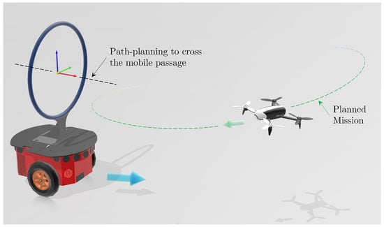
Figure 1.
The proposed approach considers both the robot’s movement’s limitations and the passages’ dimensions to ensure safe motion planning in constrained environments. The navigation strategy prioritizes obstacle avoidance and incorporates the crossing of a moving passage into the regularly planned path. This is achieved by overlapping the regular navigation path (depicted in light green) with a black dashed line that ensures flight through the identified passage. By integrating these elements, smooth trajectory execution is guaranteed while avoiding collisions with the moving passage.
In addition to providing context, Section 1.1 reviews similar works and strategies of the literature, formulating the problem as a problem of motion planning under constraints.
1.1. Background and Related Works
Researchers have proposed various methods for generating spatial references to guide the movement of UAVs in three-dimensional (3D) space, classified as global or local planning for single or multiple agents. The key distinction between these techniques lies in the level of prior knowledge about the environment []. Global path planning focuses on finding a path in a known environment, whereas local path planning becomes more challenging when the UAV operates in a partially or fully unknown environment.
Global path-planning techniques play a crucial role in enhancing the autonomy of UAVs, encompassing three key aspects. Firstly, a comprehensive map or model of the operating environment, such as a complete 3D map or graph representation, is required. Secondly, a search algorithm is employed to determine a sub-optimal path with minimal computational effort. Lastly, secondary navigation objectives, such as energy efficiency, smoothness, turns, or continuity, are analyzed during the path search process using heuristic or metaheuristic functions. Various algorithms, including potential field [,,], A* [,], Dijkstra [,], and improved versions like LPA* [,], have been widely adopted for efficient and cost-effective path search.
To address the significant computational demands of these approaches, Majeed and Hwang [] introduced a method that focuses on path-finding within regions with a high probability of providing an optimal or sub-optimal collision-free path. This approach utilizes Constrained Polygonal Space (CPS) and an Extremely Sparse Waypoint Graph (ESWG), restricting path exploration to areas with a higher probability of containing the optimal trajectory. Additionally, Song et al. [] present a Reinforcement Learning (RL)-based framework capable of generating highly aggressive trajectories for autonomous UAV racing. The strategy is able to identify the gates/narrow passages and navigate achieving speeds of up to 60 km h−1 with a physical UAV, while performing aggressive maneuvers. Also, in terms of UAV racing, navigation into gates is crucial in some phases, as depicted in []. Rojas-Perez and Martinez-Carranza [] have developed a Deep Learning (DL) solution called DeepPilot for gate detection and localization relative to a UAV. DeepPilot utilizes a Convolutional Neural Network (CNN) that processes camera images to predict flight commands, particularly attack angle references for the UAV’s body frame. The framework assumes that the subsequent gate comes into view right after the current gate is passed. Similarly, Cui and Wang [] introduce a multi-layered planning framework based on RL incorporating distinct layers for global and local planning.
A smooth, closed path that ensures to safely pass through challenging locations is proposed in [], where waypoints in a Bèzier-based curve guarantee smoothness and continuity in curvature and torsion. A drawback is that this strategy requires a known map. In turn, in [], a reactive avoidance algorithm considering only static (known as well as unknown) obstacles is proposed. The path-planning approach is based on the wavefront algorithm.
Combining local and global path planning, Bai et al. [] propose a optimum path search strategy while ensuring accomplishing security and speed requirements. The A* algorithm process the map to find an obstacle-free path according to the motion constraints. Thereafter, the DWA algorithm performs a local optimization. Therefore, the key points of the global path are constructed as the subtarget points of the local path planning selected by DWA, reducing the planning time and the path length. Tang et al. [] integrate the enhanced Particle Swarm Optimization (PSO) algorithm, the refined artificial potential algorithm, a path exploration switching strategy, and an energy-based task scheduling mechanism to develop a unified global and local path planning optimization approach. This method adapts the path planning mode based on the global and local obstacle conditions while incorporating site-specific details to assign a surveillance task to the UAV effectively.
In this context, the present work primarily concentrates on deterministic, geometry-based path planning methods, aiming to ensure secure and safe maneuvers for UAVs operating in environments with motion restrictions and various challenges. The proposed concept is designed to be dependable and efficient, providing a path that minimizes complexity by adopting a linear curve shape.
1.2. Aims and Work Contributions
In this context, the proposed approach involves utilizing waypoints along linear curves, determined by the geometry of narrow passages, their current states and velocities, and the UAV’s current pose, to ensure safe motion planning in confined spaces. The primary contribution is the generation of a smooth, continuous, and oriented path that can be time-parameterized for trajectory-tracking purposes. Despite its simplicity in terms of geometry and complexity, this method offers a reliable option for predictable robot behavior in constrained environments. More specifically, the key contribution lies in the development of a strategy for planning paths through mobile narrow passages and controlling the UAV to navigate them, using knowledge of obstacle positions. Object detection within the environment is outside the scope of this work, and is suggested as a potential avenue for future research.
To address the topics of interest, this manuscript is, hereinafter, split into a few sections. Firstly, Section 2 provides a detailed explanation of the proposed mission planning strategy. Subsequently, Section 2.2 elucidates the primary path-planning strategy employed to navigate a mobile passage on a moving Unmanned Ground Vehicle (UGV), taking into account the constraints imposed by the environment. Section 3 discusses the dynamic model of the robots, as well as the controllers used to guide them. Section 4 presents and analyzes the results of an experiment conducted using a Pioneer 3-DX unicycle mobile platform (representing the UGV) and a Parrot Bebop 2 quadrotor (tasked with passing through a vertically positioned hollow ring mounted on the UGV), showcasing the outcomes in detail. Lastly, Section 5 summarizes the main conclusions drawn from the research conducted.
2. Mission Planning and the Strategy to Cross Moving Narrow Passages
The ability to navigate through narrow passages is a crucial skill for aerial robots in many applications, such as structure inspection and surveillance in urban environments, for the necessity of managing the restrictions imposed by the local environmental boundaries (e.g., to avoid buildings and sidewalks). However, this task presents meaningful challenges, especially when the passage through which the UAV should navigate is in motion. The scenario described here presents a challenging task of path planning in dynamic environments, which is an active and evolving research area. Numerous strategies have been proposed to tackle this problem effectively.
This section introduces a path-planning strategy specifically designed for aerial robots, with a primary focus on enabling navigation through moving narrow passages. This strategy incorporates object detection, empowering the aerial robot to detect and respond to moving obstacles in real-time.
2.1. Mission Planning
The tasks assigned to the robot for a given mission are planned, and the control references to be reached or followed are generated. Task scheduling and allocation determine the execution order and assign responsibility to the appropriate agent. The robots follow an 8-shaped trajectory, known as the lemniscate of Bernoulli, depicted as the dashed green line in Figure 1, with the green arrow indicating their movement direction. Mathematically, the robots track the 8-shaped trajectory in opposite directions, described by the desired position,
where represents a constant offset value, and are the movement radii, and is the angular velocity. In this work, , , and .
In certain scenarios, however, the UAV encounters a moving narrow passage that coincides with its current calculated reference. To avoid a collision with the moving object, the UAV must either deviate or cross the passage, provided that it ensures safe crossing. This determination depends on the UAV’s dimensions, the narrow passage’s size, and the estimation of its state and velocity relative to the UAV’s dynamics and speed limits. Accurate information is essential for avoiding collisions during the crossing.
After checking that flying across the passage is possible, the strategy proposed here is to change the main mission assigned to the UAV to a path-planning algorithm that prioritizes crossing the moving narrow passage safely, resuming the original mission after leaving such passage behind. Thus, the robot navigates reactively, prioritizing its mission until facing a static/moving obstacle.
The procedure for determining a path through a narrow passage starts by searching a waypoint or constructing a visibility graph from the robot’s current position upon detecting the moving obstacle and progressing the data until the target is located, i.e., the opposite side of the narrow passage. The effectiveness of a path-planning method usually depends on selecting waypoints from a given graph that contributes to an optimal or near-optimal path with minimizing the computation effort. This work addresses the UAV path-planning problem, aiming to reduce the complexity without degrading the path quality. Accordingly, a novel approach is proposed to incorporate the robot’s state and its surroundings into the spatial motion planning process.
2.2. Spatial Path-Planning
Instead of relying on traditional obstacle avoidance techniques, this approach incorporates the geometry, as well as the estimated pose and velocity of the narrow passage, as additional information for carefully planning the UAV’s motion. As illustrated in Figure 2a, a plane tangent to the section of a passage (defined by the green and blue vectors) is considered. By considering its instantaneous normal unit vector (depicted as the red arrow), located at the centroid of such movement-restrainers, once assured that this passage is large enough to be crossed by the robot, the pair can be adopted as the desired pose. This pose is the rotated by 90° around the estimated z-axis (depicted as the blue arrow) to enable the UAV to navigate through complex static or dynamic segments in its path. The simplicity of a line segment connecting two points is used to achieve this motion planning.
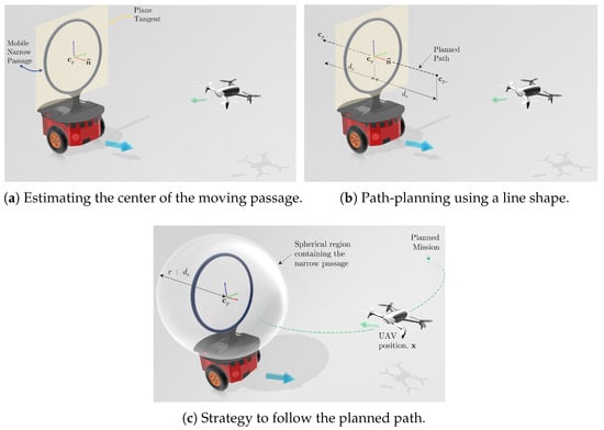
Figure 2.
Taking the centroid of a generic narrow passage (blue ring) to propose a path through the passage (dashed dark line). The robot follows such a path only if it is guaranteed that it will not collide with the ring borders. The UAV should cross the passage only when it is inside a virtual moving sphere of prescribed radius, centered in .
Once the pair is known, a safety distance from movement-restrainers is set based on the dimensions of the robot, to calculate
thus computing a line segment from to , passing through with the same orientation as , guaranteeing a path through generic narrow passages, as shown in Figure 2b. In this work, a proof of concept is demonstrated in order to elucidate the application of the proposed strategy. However, in practical terms, the structures found in real environments are generally more complex and have specific curvatures. In this sense, the proposed strategy can be extended by a more elaborate curve, with smoothly and continuously connected line segments, for example, based on Bézier curves.
Once the UAV identifies an oriented path through all movement constraints, it must determine on how and when to transition from its current pose to in a safe and smooth manner, considering its potentially restricted surroundings. Additionally, it is essential to establish the point at which the UAV successfully traverses the narrow passage, allowing it to resume its primary mission. Specifically, upon reaching , the task scheduling system should instruct the UAV to continue its main task.
In summary, the whole process of tracing line segments is repeated for each restrictive passage in the environment, as summarized in Algorithm 1. Subsequently, a control strategy should be developed to benefit from the properties of this path-planning method, ensuring that different UAVs can effectively apply it to navigate narrow passages.
| Algorithm 1 Path-planning for moving narrow passages. |
|
2.3. Path-Following
The path-following algorithm is based on the carrot-chasing strategy, which has already been demonstrated to be both stable and effective []. To enhance control adaptability for various UAVs, the reference velocity is introduced as , composed of two components. The first is tangent to the path, denoted as and illustrated by the yellow arrows in Figure 3. The second is tangent to the positioning error between the UAV and the nearest point on the path, denoted as and represented by the orange arrows in the same figure.
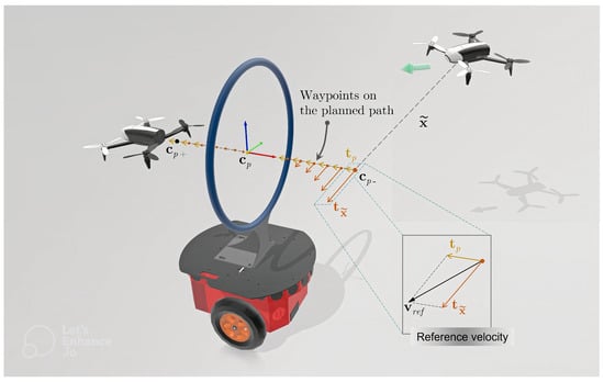
Figure 3.
Reference velocity () defined with a component tangent to the path, , and a component tangent to the vector of path-following error, .
As the robot approaches the path, the component reduces, because the position and the path-following error also reduce. As the robot moves closer to the path, the resulting reference velocity tends to approach the component tangent to the path, until only remains. At this point, the robot crosses the moving passage in the opposite direction of its movement. The idea behind this approach is to generate an attractive force to make the robot approach the path as quickly as possible, i.e., to approach the line with origin in the geometric center of the moving obstacle. Once the path is reached, the tangential component of the error between the robot and the nearest point on the path becomes small enough, and the robot can track the path and cross the obstacle safely.
Describing the path as a succession of equally spaced k waypoints, , along the coordinates from to , we can define the position error as , where i denotes the point on the path that is closest to the robot at a given time instant. Thus, we can define a vector tangent to the position error as , where is a gain matrix, denoting the aggressiveness that the robot approaches the path. The path tangent direction at a given waypoint, , can be directly obtained as the unit vector along the segment from to .
Finally, assuming as an additional control objective, the reference velocity to be sent to the UAV, which is given by
where is a user-defined scalar that is set as a value lower than the maximum velocity that the UAV can achieve. On the other hand, denotes the minimum distance required for the robot to be considered as having reached the path.
Assuming that the exact/estimated current UAV position () and the position of the centroid of the narrow passage () are known, one can define the path waypoints and the limited region in which the robot reference becomes the straight line segment generated by the path-planning algorithm to cross the moving narrow passage. Given that the primary control objective is to accurately track the predefined trajectory, the UAV leaves its regular mission only when necessary. Specifically, the UAV deviates from its intended path upon entering a spherical region centered around the estimated position of the narrow passage section’s centroid, as shown in Figure 2c. The moving obstacle is accompanied by a spherical region that surrounds it. This region has a radius larger than the predefined security distance , with an additional term r to ensure that the entire passage is contained within this region. However, note that the UAV only proceeds with this step after confirming that it is indeed feasible to safely cross the passage.
3. Robots Dynamic Modeling and Control
In this work, the proof of concept of the proposal is validated through experiments with UAVs and Unmanned Ground Vehicles (UGVs) carrying cylinders, which represent mobile narrow passages. In order to apply the proposed path planning strategy, a previously validated kinematic models was applied alongside with dynamic compensation towards computing valid control signals for the UGV and the UAV, in simulations and experiments. Parameters needed to compute the dynamic compensation were identified in the literature, and are described in the following.
3.1. The UGV Model and Control
In this work, we used the Pioneer P3-Dx, a unicycle like mobile robot, for which the kinematic model can be described as shown in Figure 4. Considering that navigation occurs only in a horizontal plane, the robot pose is , in which x and y are the coordinates of the control point located at the center of the virtual axis that joins its wheels , and is its heading with respect to its x axis, based on the inertial frame . Also, u and are the linear and angular velocities of the robot, respectively, and is the vector composed of this velocities. The non-zero constant a is the distance from the origin of the body axes (the virtual line linking the two driven wheels) to the point of interest for control purposes. Note also that the mobile robot is seeking the goal/target, with specific orientation , represented by the reference in .
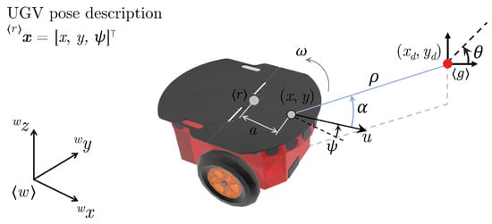
Figure 4.
Spatial unicycle-type robot representation and polar modeling variables (in blue). The target point is represented by .
The system of kinematics equations describing the motion of the robot over time in the Cartesian plane is presented in [,]. The UGVs used in this work are a unicycle-type mobile robot, whose kinematic model is given by
in which and represent the x and y components of the robot’s current linear velocity represented in the inertial frame , is its angular velocity. Additionally, u and are the control inputs—namely, the linear and the angular velocity, respectively.
Representing the robot navigation in polar coordinates, we have
in which is the robot-destination distance, is the orientation of reference in the target point, and is the heading error to the destination.
In this work, the navigation circuit consists of a set of waypoints without any time constraints. Thus, the robot executes a regulation (positioning) task, where the temporal derivatives of the reference positions are zero. With this understanding, taking the first time derivative of (4) and replacing (3) yields the kinematic model expressed in polar coordinates.
in which .
Assuming that the sequence of waypoints prioritizes task-oriented arrival, we design a controller without a specified final orientation. In this scenario, is treated as a free variable, constrained only to remain bounded at the final state. Using Lyapunov theory as a foundation, we propose the following radially unbounded candidate function:
Applying the feedback linearization technique, we can propose the kinematic control signal,
in which is a positive defined gain matrix.
After applying its first time derivative in (6), and replacing (5) and (7), we obtain
This establishes the global asymptotic convergence of as , indicating that the robot will reach its target in an obstacle-free environment. Furthermore, as a direct result, is also achieved as .
The same control law can be applied to trajectory-tracking tasks. For our UGV, good performances at low-speed are achieved just assuming perfect velocity tracking, i.e., and . However, in most applications, especially those performed at high speeds, the robot’s kinematic model alone is not able to track and follow trajectories and/or paths efficiently and accurately. Thus, for the design of motion controllers, it is of paramount importance to consider the robot’s dynamic modeling. This UGV is equipped with an embedded low-level controller that operates the vehicle’s two motors, allowing the implementation of the previously mentioned high-level linear and angular velocity commands, . To deal with the dynamic effects caused by inertia and friction, a dynamic model first introduced in [] and updated in [] was used.
The robot dynamic model in the compact form is presented by [] as
where and are the Inertia and Coriolis matrices, respectively.
A positioning control described in the Cartesian space can be achieved using inverse dynamics and considering a desired trajectory. The reference velocity command can be defined as
where is a positive definite gain matrix and is the direct kinematics matrix defined in [,].
To contemplate applications in which the robot needs to navigate under high-speed movements, and to evaluate a more realistic scenario, a dynamic compensation module is adopted. Considering (9), the adopted dynamic compensation control law is given by
in which the gain is a positive definite matrix and is the velocity tracking error. The control signal is obtained by numeric differentiation considering the sampling time of the control loop.
The saturation of the physical actuators introduces unpredicted non-linearities in the system, which may cause instability. Although a non-linearity is inserted in the control law, the term is used in (10), saturating the control signals for large position errors. This non-linearity is considered in the system stability analysis. The advantage of using it is to prevent the saturation of the robot actuators, guaranteeing good behavior, even for large errors and .
Now, the use of the proposed dynamic model and its properties is illustrated via the design of an dynamic compensation controller. It receives the desired control signals from the kinematic controller and generates a pair of linear and angular velocity references for the robot servos, as shown in the diagram block of Figure 5.

Figure 5.
The dynamic control system responsible for guiding the UGV to the destination.
Furthermore, the choice of over other saturation functions, such as , is because is differentiable and smooth, avoiding fast commutations and chattering effects.
3.2. The UAV Model and Control
The Bebop 2 quadcopter, produced by Parrot Inc., is a small UAV with an onboard stabilization system and an ad hoc network communication interface for the delivery of various information. Among the most transparent data to the user, we have the following variables: vehicle altitude relative to the surface, the longitudinal and lateral translation speeds in the vehicle body, and the Tait–Bryan angles in the global referential. For control purposes, the vector of such states is given by .
The mathematical model to be adopted for navigation and control proposals is the one described in [,], referring to the description presented in Figure 6. The translational coordinates of the quadrotor are , and its attitude is described by the vector , which contains the roll, pitch, and yaw Tait–Bryan angles, both related to the inertial reference frame . The Newton–Euler dynamics correspondent to the used quadrotor, and its simplified form is presented in []. Such a simplification performs well for roll and pitch angles up to approximately 30°, corresponding to linear velocities of approximately 1.5–2 m/s [].
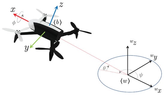
Figure 6.
Parrot Bebop 2 description and pose variables, according to Tait–Bryan angle notation.
A near-hover model for the quadrotor can be written in the linear form
in which is the pose vector (position in frame , and orientation, namely the yaw heading). Meanwhile, the vector of control signals contemplates the commands referring to the pitch angle and to the rolling one, while and relate to the rate of change in linear and angular velocity along the axis , respectively, all in the interval [−1, +1].
The matrices and are diagonal matrices containing, respectively, the dynamic and drag parameters for the model, identified through an identification procedure []. The vector contains the reference control signal for a desired trajectory. is a simplified transformation matrix, also known as the kinematic model, relating the vehicle’s and the global coordinate systems, only dependent of ,
The reference signal can be obtained using a PD feedback compensator plus a feedforward term, which corresponds to . In this formulation, is the defined task, which can be trajectory tracking or positioning. is the control error, and and are positive definite gain matrices.
So, we can rewrite the control law in (12) as
The diagram block describing the implemented controller is shown in Figure 7.

Figure 7.
The dynamic control system responsible for guiding the UAV to the target point.
3.3. Stability Analysis of the Controllers
For the successful experimental evaluation of the proposed high level task allocation planner, all utilized robots must have the following prerequisite skills: dynamic stability for the preselected set of tasks, ability to localize themselves, plan and execute obstacle free trajectories, as well as the infrastructure through which they can share information and negotiate task allocation. The controllers presented for the UAV, (14), and UGV, (11), were designed using the feedback linearization technique, which assumes a perfect knowledge of the models parameters. Under these assumptions, the proposed controllers make the system asymptotically stable when closing the loop, as presented in [].
In order to analyze the stability of the equilibrium of the rotorcraft system when using the proposed control law, one can write, in closed-loop, the equation that describes the dynamics of the posture errors,
The candidate Lyapunov’s function
is proposed. Taking its first-time derivative and using (15), the closed-loop equation, one has
from where a sufficient condition to guarantee that is negative semi-definite is and are positive definite.
Now, applying the La Salle theorem for autonomous systems, taking into account the dynamics of the system given by (15) and disregarding the disturbances, one can note that the largest invariant set contained in the set is . This demonstrates that the system (and, consequently, the tracking/regulation error origin) is asymptotically stable. Mathematically, for .
In this work, we assume that the map of the environment is a priori known, and that each vehicle knows its exact position. In practice, this is difficult to achieve without utilization of self-localization and map-building algorithms. We leave this part of the system for future work and development, but for now, we can achieve this through a combination of motion tracking system and a priori known environment.
4. Experiments, Results, and Discussion
After presenting the theoretical formulation, to assess the effectiveness and performance of the proposed motion planning strategy, a series of experiments was conducted. The experiments aimed to evaluate the strategy’s capability to navigate through narrow passages in dynamic environments. For this purpose, a circular hoop was mounted on a moving unicycle robot, serving as a representation of the narrow passages, as depicted in Figure 8.
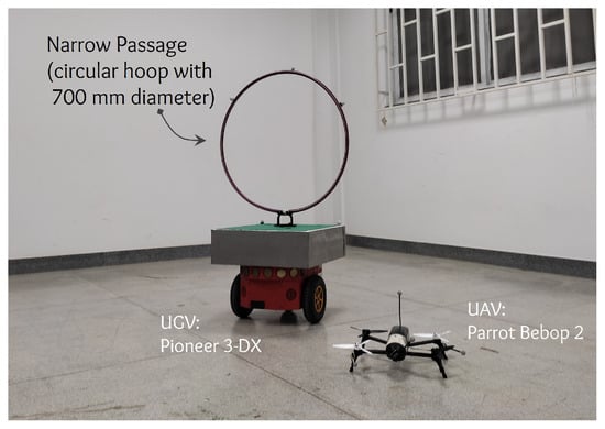
Figure 8.
Robots configuration and circular hoop dimensions.
The Bebop Parrot 2 is the UAV used in our experiments, whose dimensions are inscribed in a prism. It is worth emphasizing that the UAV successfully traverses the circular hoop while maintaining a safety margin.
Figure 9 shows an overview of the setup used to run the experiment. The positions of the two robots were obtained using an installation of the motion capture system OptiTrack, composed of eight infrared cameras detecting and tracking the robots (and, thus, the passage) in a indoor environment. As one can see in the experimental setup, two computers, a Windows 10 desktop and a Linux laptop, were used. The first runs the OptiTrack and Motive 3.1.0 software for motion capture and a MATLAB® script, which computes the path-planning algorithm and generates the control signals. As for the Linux laptop, it contains the ROS nodes necessary to send/receive data from/for the Bebop 2. The two robots used are also shown in the figure, with the reflective markers used in connection with the OptiTrack system. Notice that the Pionner 3-DX has a circular hoop on its top, across which the UAV should fly, whose diameter is 700 mm, which represents a particularly challenging geometric constraint, especially when in motion.
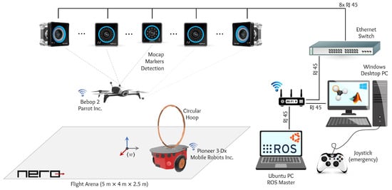
Figure 9.
Experimental setup.
Both vehicles were programmed to perform a trajectory tracking task, with a trajectory shaped as a lemniscate of Bernoulli. A video of the experiment is available at https://youtu.be/KrNmOUjahy8 (accessed on 1 January 2025), which allows one to better understand the experiment. Snapshots showing the behavior of the UAV according to the proposed strategy are presented in Figure 10. Both robots initiate the experiment from a stationary position, and are tasked with following the same trajectory. However, they move in opposite directions, creating challenging position conditions where they cross each other.
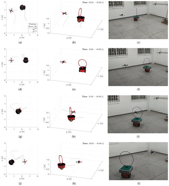
Figure 10.
Experiment conducted to validate the strategy for identifying and cross the hoop. The left column refers to a top view of the robot state at the determined instant. The central column presents isometric views of the scenario at the highlighted moments. The right column are snapshots extracted from the video of the experiment. The chart legend are determined as: path traveled by the robot (continuous gray curve), path traveled by the moving narrow passage (continuous red curve), and planned trajectory for the UAV (dashed gray line). Each horizontal group of figures is referred to the same snapshot of the experiment: (a–c) [s], (d–f) [s], (g–i) [s] and, finally, (j–l) [s].
When the UAV detects that it is near the narrow mobile passage, i.e., an obstacle that is not part of its original mission, it checks the possibility of crossing the object. The path-following stage begins when the UAV enters the virtual sphere encompassing the obstacle. Therefore, the planning algorithm overlays the reference originated from the original UAV mission with the path planned to cross the passage, so that the UAV momentarily abandons its original task and prioritizes a safe crossing. A snapshot of the moment when the UAV crosses the hula hoop can be observed in Figure 10g–i.
Notice that the UAV effectively navigates through the passage while maintaining a safety margin. The path planning algorithm calculates the UAV’s trajectory, ensuring that its intersection with the plane corresponding to the hula hoop is as close as possible to the geometric center of the hoop. This strategy enables the UAV to cross the passage accurately and safely. After crossing the moving obstacle, the UAV resumes its original mission, restarting the trajectory-tracking task, as can be seen in Figure 10j–l.
The dashed line in the figures in the left column of Figure 10 (see Figure 10a,d,g,j) represents the route planning for the UAV, which means that during the execution of its mission, the final planned route is not exactly the tracking of the trajectory defined as its main mission. Thus, the result observed in Figure 11a is not exactly a Bernoulli lemniscate, as expected. As a mater of fact, it presents sections where the robot abandoned its main mission to follow the proposed path, which makes it possible to cross the mobile passage safely. It is also important to note that the abrupt change in the type of planned task (from trajectory-tracking to path-following, and vice versa) also affects the robot behavior in the z-axis direction, as it can be seen in Figure 12a.
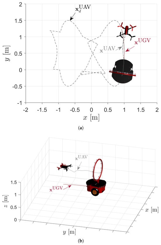
Figure 11.
Last stage of the experiment. (a) Top view of the planned route and (b) isometric view of the routes traveled by the UAV (gray line) and the UGV carrying the circular hoop (red line).
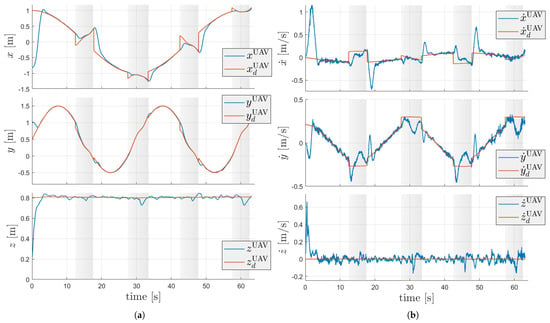
Figure 12.
UAV behavior during the experiment. (a) Time variation of the robot position and task reference. (b) Time variation of the velocity error.
Observing Figure 12a, it is possible to identify the exact moments when the robot started the path-planning algorithm to cross the mobile passage, thus overlapping the reference given by the planned mission. The time-span when the robot performed the crossings during its route is indicated by the rectangular regions with a gray background. Note that, at the beginning and end of each of these regions, both the trajectory-tracking errors and path-following errors show spikes in their curves. This is due to the abrupt change in the motion reference calculated by the task planning and sent to the control system. Again, it is important to emphasize that the implemented control law is capable of tracking the proposed trajectory with zero steady-state error, as observed in the white regions in the graph. The behavior of the UAV is asymptotically stable, due to the applied control law, as expected. Furthermore, it is observed that the control error increases abruptly at each moment when the UAV starts/ends the path following, i.e., at the exact instants when it enters/exits the virtual sphere that comprises the obstacle.
At the first moment when the UAV identifies the circular passage and ensures a safe crossing, it initializes the process of generating a safe path to cross the platform. The straight-line path is moving along with the circular passage and, therefore, at the moments when the UAV meets the hula hoop, the route executed by the UAV until crossing the passage may present a different shape from a straight line in space. This can be easily observed in Figure 12a, where it is noted that in the moments of crossing (sections marked with gray background), the desired and effectively executed position profiles approach a straight line in the intervals of 10 to 20 and 40 to 50 s, when the robots cross in the linear section of the planned trajectory. However, in the sections between 25 and 35 s, as well as between 55 and 65 s, the planned path moves in such a way that the robot needs to follow a rounded route to ensure a safe passage, as the orientation of the hula hoop is changing as it moves along the trajectory.
Finally, we would like to highlight the observed velocity profile during the experiment, as shown in Figure 12b. It is evident that the velocity tracking error exhibits significant oscillations when the robot is on the path. This behavior arises from the fact that the robot receives a constant reference velocity magnitude, while both the UAV and the path are in motion. As a result, the robot accelerates to match the path’s speed and aligns itself with the hoop for successful passage. However, it needs to decelerate to attain the desired speed at each point on the path. During deceleration, the velocity error increases due to the hoop moving in the opposite direction of the UAV, prompting the UAV to accelerate once again to correct the error. The intervals of approximately constant velocity correspond to the planned velocities along the path.
5. Concluding Remarks
In summary, we presented a closed and smooth path that ensures safe motion in such scenarios, based on the physical limitations of the robot and its environment, taking advantage of the known geometric properties. Experimental results demonstrated that the UAV-UGV system effectively planned a safe path and successfully navigated through the moving obstacle with minimal control errors. The system showcased its potential for cooperative UAV-UGV applications, including search and rescue, surveillance, and inspection tasks. Future research endeavors could focus on assessing the scalability of the proposed system and its performance in more intricate and challenging environments. One potential avenue for refinement is the integration of Visual Simultaneous Localization and Mapping (VSLAM) techniques and advanced object detection algorithms to enhance the autonomy of the UAV in both motion and planning tasks. These advancements would contribute to improving the system’s adaptability and effectiveness in various applications.
Author Contributions
Conceptualization, L.A.F.-J. and D.K.D.V.; methodology, L.A.F.-J.; validation, L.A.F.-J., D.K.D.V. and A.S.B.; resources, A.S.B. and M.S.-F.; data curation, L.A.F.-J.; writing original draft preparation, L.A.F.-J.; writing, L.A.F.-J., review and editing, A.S.B., D.K.D.V. and M.S.-F.; supervision, A.S.B.; project administration, A.S.B.; funding acquisition, A.S.B. and M.S.-F. All authors have read and agreed to the published version of the manuscript.
Funding
This work was financially supported by FAPEMIG—Fundação de Amparo à Pesquisa do Estado de Minas Gerais (Grant Number 02282-24).
Data Availability Statement
Data are contained within the article.
Conflicts of Interest
The authors declare no conflicts of interest.
Abbreviations
The following abbreviations are used in this manuscript:
| UAV | Unmanned Aerial Vehicle |
| UGV | Unmanned Ground Vehicle |
| GPS | Global Positioning Systems |
| CPS | Constrained Polygonal Space |
| ESWG | Extremely Sparse Waypoint Graph |
| RL | Reinforcement Learning |
| DL | Deep Learning |
| CNN | Convolutional Neural Network |
| PSO | Particle Swarm Optimization |
References
- Chen, S.; Laefer, D.F.; Mangina, E. State of Technology Review of Civilian UAVs. Recent Patents Eng. 2016, 10, 160–174. [Google Scholar] [CrossRef]
- Muchiri, G.; Kimathi, S. A review of applications and potential applications of UAV. In Proceedings of the Sustainable Research and Innovation Conference, Nairobi, Kenya, 4–6 May 2016; pp. 280–283. [Google Scholar]
- Adade, R.; Aibinu, A.M.; Ekumah, B.; Asaana, J. Unmanned Aerial Vehicle (UAV) applications in coastal zone management—A review. Environ. Monit. Assess. 2021, 193, 154. [Google Scholar] [CrossRef] [PubMed]
- Shakhatreh, H.; Sawalmeh, A.H.; Al-Fuqaha, A.; Dou, Z.; Almaita, E.; Khalil, I.; Othman, N.S.; Khreishah, A.; Guizani, M. Unmanned aerial vehicles (UAVs): A survey on civil applications and key research challenges. IEEE Access 2019, 7, 48572–48634. [Google Scholar] [CrossRef]
- Alotaibi, E.T.; Alqefari, S.S.; Koubaa, A. Lsar: Multi-uav collaboration for search and rescue missions. IEEE Access 2019, 7, 55817–55832. [Google Scholar] [CrossRef]
- Lyu, M.; Zhao, Y.; Huang, C.; Huang, H. Unmanned aerial vehicles for search and rescue: A survey. Remote Sens. 2023, 15, 3266. [Google Scholar] [CrossRef]
- Lygouras, E.; Santavas, N.; Taitzoglou, A.; Tarchanidis, K.; Mitropoulos, A.; Gasteratos, A. Unsupervised human detection with an embedded vision system on a fully autonomous UAV for search and rescue operations. Sensors 2019, 19, 3542. [Google Scholar] [CrossRef]
- Zhao, S.; Kang, F.; Li, J.; Ma, C. Structural health monitoring and inspection of dams based on UAV photogrammetry with image 3D reconstruction. Autom. Constr. 2021, 130, 103832. [Google Scholar] [CrossRef]
- Hayajneh, M.; Al Mahasneh, A. Guidance, Navigation and Control System for Multi-Robot Network in Monitoring and Inspection Operations. Drones 2022, 6, 332. [Google Scholar] [CrossRef]
- Aela, P.; Chi, H.L.; Fares, A.; Zayed, T.; Kim, M. UAV-based studies in railway infrastructure monitoring. Autom. Constr. 2024, 167, 105714. [Google Scholar] [CrossRef]
- Amarasingam, N.; Salgadoe, A.S.A.; Powell, K.; Gonzalez, L.F.; Natarajan, S. A review of UAV platforms, sensors, and applications for monitoring of sugarcane crops. Remote Sens. Appl. Soc. Environ. 2022, 26, 100712. [Google Scholar] [CrossRef]
- Jenssen, R.; Roverso, D.; Roverso, D. Intelligent monitoring and inspection of power line components powered by UAVs and deep learning. IEEE Power Energy Technol. Syst. J. 2019, 6, 11–21. [Google Scholar]
- Barcelos, C.O.; Fagundes-Júnior, L.A.; Villa, D.K.D.; Sarcinelli-Filho, M.; Silvatti, A.P.; Gandolfo, D.C.; Brandão, A.S. Robot Formation Performing a Collaborative Load Transport and Delivery Task by Using Lifting Electromagnets. Appl. Sci. 2023, 13, 822. [Google Scholar] [CrossRef]
- Saunders, J.; Saeedi, S.; Li, W. Autonomous aerial robotics for package delivery: A technical review. J. Field Robot. 2024, 41, 3–49. [Google Scholar] [CrossRef]
- Saponi, M.; Borboni, A.; Adamini, R.; Faglia, R.; Amici, C. Embedded payload solutions in UAVs for medium and small package delivery. Machines 2022, 10, 737. [Google Scholar] [CrossRef]
- Deng, X.; Guan, M.; Ma, Y.; Yang, X.; Xiang, T. Vehicle-assisted uav delivery scheme considering energy consumption for instant delivery. Sensors 2022, 22, 2045. [Google Scholar] [CrossRef]
- Akhtar, A.; Saleem, S.; Shan, J. Path Invariant Controllers for a Quadrotor With a Cable-Suspended Payload Using a Global Parameterization. IEEE Trans. Control Syst. Technol. 2021, 30, 2002–2017. [Google Scholar] [CrossRef]
- Cardoso, E.S.; Bacheti, V.P.; Sarcinelli-Filho, M. Package Delivery Based on the Leader-Follower Control Paradigm for Multirobot Systems. In Proceedings of the 2023 International Conference on Unmanned Aircraft Systems (ICUAS’23), Warsaw, Poland, 6–9 June 2023. [Google Scholar]
- Puniach, E.; Gruszczyński, W.; Ćwiąkała, P.; Matwij, W. Application of UAV-based orthomosaics for determination of horizontal displacement caused by underground mining. ISPRS J. Photogramm. Remote Sens. 2021, 174, 282–303. [Google Scholar] [CrossRef]
- Park, S.; Choi, Y. Applications of unmanned aerial vehicles in mining from exploration to reclamation: A review. Minerals 2020, 10, 663. [Google Scholar] [CrossRef]
- Ćwiąkała, P.; Gruszczyński, W.; Stoch, T.; Puniach, E.; Mrocheń, D.; Matwij, W.; Matwij, K.; Nędzka, M.; Sopata, P.; Wójcik, A. UAV applications for determination of land deformations caused by underground mining. Remote Sens. 2020, 12, 1733. [Google Scholar] [CrossRef]
- Freire, V.; Xu, X. Flatness-based quadcopter trajectory planning and tracking with continuous-time safety guarantees. IEEE Trans. Control Syst. Technol. 2023, 31, 2319–2334. [Google Scholar] [CrossRef]
- Bolourian, N.; Hammad, A. LiDAR-equipped UAV path planning considering potential locations of defects for bridge inspection. Autom. Constr. 2020, 117, 103250. [Google Scholar] [CrossRef]
- Ma, X.; Jiao, Z.; Wang, Z.; Panagou, D. 3-d decentralized prioritized motion planning and coordination for high-density operations of micro aerial vehicles. IEEE Trans. Control Syst. Technol. 2017, 26, 939–953. [Google Scholar] [CrossRef]
- Roucek, T.; Pecka, M.; Cızek, P.; Petrıcek, T.; Bayer, J.; Šalansky, V.; Azayev, T.; Hert, D.; Petrlık, M.; Báca, T.; et al. System for multi-robotic exploration of underground environments CTU-CRAS-NORLAB in the DARPA subterranean challenge. arXiv 2021, arXiv:2110.05911. [Google Scholar]
- Muller, M.; Li, G.; Casser, V.; Smith, N.; Michels, D.L.; Ghanem, B. Learning a controller fusion network by online trajectory filtering for vision-based uav racing. In Proceedings of the IEEE/CVF Conference on Computer Vision and Pattern Recognition Workshops, Long Beach, CA, USA, 16–17 June 2019. [Google Scholar]
- Ribeiro, R.; Ramos, J.; Safadinho, D.; de Jesus Pereira, A.M. UAV for everyone: An intuitive control alternative for drone racing competitions. In Proceedings of the 2018 2nd International Conference on Technology and Innovation in Sports, Health and Wellbeing (TISHW), Thessaloniki, Greece, 20–22 June 2018; pp. 1–8. [Google Scholar]
- Madaan, R.; Gyde, N.; Vemprala, S.; Brown, M.; Nagami, K.; Taubner, T.; Cristofalo, E.; Scaramuzza, D.; Schwager, M.; Kapoor, A. Airsim drone racing lab. In Proceedings of the Neurips 2019 Competition and Demonstration Track, PMLR, Vancouver, BC, Canada, 8–14 December 2020; pp. 177–191. [Google Scholar]
- Aggarwal, S.; Kumar, N. Path planning techniques for unmanned aerial vehicles: A review, solutions, and challenges. Comput. Commun. 2020, 149, 270–299. [Google Scholar] [CrossRef]
- Yang, L.; Qi, J.; Xiao, J.; Yong, X. A literature review of UAV 3D path planning. In Proceeding of the 11th World Congress on Intelligent Control and Automation, Shenyang, China, 29 June–4 July 2014; pp. 2376–2381. [Google Scholar]
- Spedicato, S.; Notarstefano, G. Minimum-time trajectory generation for quadrotors in constrained environments. IEEE Trans. Control Syst. Technol. 2017, 26, 1335–1344. [Google Scholar] [CrossRef]
- Cui, Z.; Wang, Y. UAV path planning based on multi-layer reinforcement learning technique. IEEE Access 2021, 9, 59486–59497. [Google Scholar] [CrossRef]
- Chen, Y.b.; Luo, G.c.; Mei, Y.s.; Yu, J.q.; Su, X.l. UAV path planning using artificial potential field method updated by optimal control theory. Int. J. Syst. Sci. 2016, 47, 1407–1420. [Google Scholar] [CrossRef]
- Khuswendi, T.; Hindersah, H.; Adiprawita, W. Uav path planning using potential field and modified receding horizon a* 3d algorithm. In Proceedings of the 2011 International Conference on Electrical Engineering and Informatics, Bandung, Indonesia, 17–19 July 2011; pp. 1–6. [Google Scholar]
- Hao, G.; Lv, Q.; Huang, Z.; Zhao, H.; Chen, W. Uav path planning based on improved artificial potential field method. Aerospace 2023, 10, 562. [Google Scholar] [CrossRef]
- Chen, T.; Zhang, G.; Hu, X.; Xiao, J. Unmanned aerial vehicle route planning method based on a star algorithm. In Proceedings of the 2018 13th IEEE Conference on Industrial Electronics and Applications (ICIEA), Wuhan, China, 31 May–2 June 2018; pp. 1510–1514. [Google Scholar]
- Zhang, Z.; Wu, J.; Dai, J.; He, C. A novel real-time penetration path planning algorithm for stealth UAV in 3D complex dynamic environment. IEEE Access 2020, 8, 122757–122771. [Google Scholar] [CrossRef]
- He, Z.; Zhao, L. The comparison of four UAV path planning algorithms based on geometry search algorithm. In Proceedings of the 2017 9th International Conference on Intelligent Human-Machine Systems and Cybernetics (IHMSC), Hangzhou, China, 26–27 August 2017; Volume 2, pp. 33–36. [Google Scholar]
- Dong, D.; Xing, L.; Zheng, L.; Jia, Y.; Sun, D. Automated 3-d electromagnetic manipulation of microrobot with a path planner and a cascaded controller. IEEE Trans. Control Syst. Technol. 2021, 30, 2672–2680. [Google Scholar] [CrossRef]
- Yang, L.; Qi, J.; Song, D.; Xiao, J.; Han, J.; Xia, Y. Survey of Robot 3D Path Planning Algorithms. J. Control Sci. Eng. 2016, 2016, 7426913. [Google Scholar] [CrossRef]
- Ahn, J.; Jung, S.; Kim, H.; Hwang, H.J.; Jun, H.B. A study on unmanned combat vehicle path planning for collision avoidance with enemy forces in dynamic situations. J. Comput. Des. Eng. 2023, 10, 2251–2270. [Google Scholar] [CrossRef]
- Majeed, A.; Hwang, S.O. Path planning method for UAVs based on constrained polygonal space and an extremely sparse waypoint graph. Appl. Sci. 2021, 11, 5340. [Google Scholar] [CrossRef]
- Song, Y.; Steinweg, M.; Kaufmann, E.; Scaramuzza, D. Autonomous drone racing with deep reinforcement learning. In Proceedings of the 2021 IEEE/RSJ International Conference on Intelligent Robots and Systems (IROS), Prague, Czech Republic, 27 September–1 October 2021; pp. 1205–1212. [Google Scholar]
- Rojas-Perez, L.O.; Martinez-Carranza, J. Deeppilot: A cnn for autonomous drone racing. Sensors 2020, 20, 4524. [Google Scholar] [CrossRef] [PubMed]
- Caldeira, A.G.; Vasconcelos, J.V.R.; Sarcinelli-Filho, M.; Brandão, A.S. UAV Path-Following Strategy for Crossing Narrow Passages. In Proceedings of the 2020 International Conference on Unmanned Aircraft Systems (ICUAS), Athens, Greece, 1–4 September 2020; pp. 26–31. [Google Scholar]
- Hebecker, T.; Buchholz, R.; Ortmeier, F. Model-based local path planning for UAVs. J. Intell. Robot. Syst. 2015, 78, 127–142. [Google Scholar] [CrossRef]
- Bai, X.; Jiang, H.; Cui, J.; Lu, K.; Chen, P.; Zhang, M. UAV Path Planning Based on Improved A-star and DWA Algorithms. Int. J. Aerosp. Eng. 2021, 2021, 4511252. [Google Scholar] [CrossRef]
- Tang, Y.; Miao, Y.; Barnawi, A.; Alzahrani, B.; Alotaibi, R.; Hwang, K. A joint global and local path planning optimization for UAV task scheduling towards crowd air monitoring. Comput. Netw. 2021, 193, 107913. [Google Scholar] [CrossRef]
- Rubí, B.; Pérez, R.; Morcego, B. A survey of path following control strategies for UAVs focused on quadrotors. J. Intell. Robot. Syst. 2020, 98, 241–265. [Google Scholar] [CrossRef]
- Brandão, A.S.; Sarcinelli-Filho, M.; Carelli, R. Leader-following control of a UAV-UGV formation. In Proceedings of the 2013 16th International Conference on Advanced Robotics (ICAR), Montevideo, Uruguay, 25–29 November 2013; pp. 1–6. [Google Scholar]
- Brandão, A.S.; Sarcinelli-Filho, M.; Carelli, R. An analytical approach to avoid obstacles in mobile robot navigation. Int. J. Adv. Robot. Syst. 2013, 10, 278. [Google Scholar] [CrossRef]
- De La Cruz, C.; Carelli, R. Dynamic model based formation control and obstacle avoidance of multi-robot systems. Robotica 2008, 26, 345–356. [Google Scholar] [CrossRef]
- Martins, F.N.; Sarcinelli-Filho, M.; Carelli, R. A velocity-based dynamic model and its properties for differential drive mobile robots. J. Intell. Robot. Syst. 2017, 85, 277–292. [Google Scholar] [CrossRef]
- De Carvalho, K.B.; Villa, D.K.D.; Sarcinelli-Filho, M.; Brandão, A.S. Gestures-teleoperation of a heterogeneous multi-robot system. Int. J. Adv. Manuf. Technol. 2022, 118, 1999–2015. [Google Scholar] [CrossRef]
- Santana, L.V.; Brandão, A.S.; Sarcinelli-Filho, M. Navigation and cooperative control using the ar. drone quadrotor. J. Intell. Robot. Syst. 2016, 84, 327–350. [Google Scholar] [CrossRef]
- Pinto, A.O.; Marciano, H.N.; Bacheti, V.P.; Moreira, M.S.M.; Brandão, A.S.; Sarcinelli-Filho, M. High-level modeling and control of the Bebop 2 micro aerial vehicle. In Proceedings of the 2020 International Conference on Unmanned Aircraft Systems (ICUAS), Athens, Greece, 1–4 September 2020; pp. 939–947. [Google Scholar]
- Tang, S.; Kumar, V. Autonomous flight. Annu. Rev. Control Robot. Auton. Syst. 2018, 1, 29–52. [Google Scholar] [CrossRef]
Disclaimer/Publisher’s Note: The statements, opinions and data contained in all publications are solely those of the individual author(s) and contributor(s) and not of MDPI and/or the editor(s). MDPI and/or the editor(s) disclaim responsibility for any injury to people or property resulting from any ideas, methods, instructions or products referred to in the content. |
© 2025 by the authors. Licensee MDPI, Basel, Switzerland. This article is an open access article distributed under the terms and conditions of the Creative Commons Attribution (CC BY) license (https://creativecommons.org/licenses/by/4.0/).