Abstract
This study investigates the application of phononic crystal plates for automotive vibration and noise attenuation through a combined material–structure design approach. Four materials—aluminum, lead, epoxy resin, and plexiglass—were selected to construct a composite plate with a low-density matrix and high-density metallic inclusions. Finite element modeling in COMSOL Multiphysics identified organic glass–lead as the optimal configuration, balancing wide bandgap performance with low-frequency characteristics and lightweight requirements. Parametric analysis demonstrated that rectangular inclusions provide the widest bandgap under equal area conditions, and increasing their volume fraction shifts the bandgap to lower frequencies while broadening its width. The study verifies the reliability of the finite element method (FEM) and further explains the formation mechanism of the bandgap. This study proposes a phononic crystal plate structure with optimal performance: a rectangular phononic crystal plate with a length of A = 20 mm and a height of B = 10 mm serves as the matrix, and four identical rectangular inclusions each with an area of S = 16 mm2 are embedded in it. The matrix material is organic glass, while the material of the inclusions is lead. The resulting optimized structure exhibits a complete Lamb wave bandgap from 6.29 to 22.03 kHz, with strong elastic wave attenuation extending over 6.00–30.00 kHz. Acoustically, it achieves sound transmission loss (STL) exceeding 130 dB within 5.85–27.91 kHz, peaking at 143.99 dB. These results verify the structure’s dual functionality in simultaneous vibration isolation and sound attenuation within the same frequency range, demonstrating the potential of phononic crystal plates for targeted noise and vibration control in automotive engines and rotating machinery.
1. Introduction
Domestic research on phononic crystal plates for vehicles has emerged in response to the urgent demand for vibration and noise control in the transportation sector. With the rapid development of China’s high-speed railway and automotive industries, the problems of low-frequency vibration and noise generated during high-speed operation have become increasingly prominent. Du Xuya [] reported that during the operation of high-speed trains, wheel–rail friction and aerodynamic noise are transmitted into the train interior via the body structure, and traditional sound-insulating materials are often ineffective in suppressing low-frequency noise (20–2000 Hz). In contrast, the bandgap characteristics of phononic crystals provide a novel solution to this problem. For example, Li Haiping’s research team [,] investigated the composite floor structure of high-speed trains and demonstrated that phononic crystal-embedded support layers can markedly enhance low-frequency insulation. By optimizing the lattice period and material combinations, they achieved an increase of over 30% in sound transmission loss within the 100–500 Hz frequency range, thereby laying a theoretical foundation for noise control in rail transit vehicles.
Chinese studies have also emphasized material optimization and engineering-oriented structural design. Fan Hao [] proposed that the bandgap width could be expanded by adjusting the shape and arrangement of scatterers, a concept that has since been widely applied in the design of automotive phononic crystal plates. Liu Wei’s team [,] focused on vibration control of automotive compressors and demonstrated that their phononic crystal structures achieved more than 30 dB attenuation within the 1000–4000 Hz range, confirming the feasibility of applying phononic crystals to critical automotive components. Collectively, these investigations illustrate how Chinese research integrates theoretical principles with practical automotive scenarios, advancing the engineering application of phononic crystal plates.
In contrast, international studies, that were initiated earlier, have placed greater emphasis on fundamental theories and wave characteristics, thereby providing strong theoretical support for automotive applications. Vasseur J.O. [] and colleagues systematically described the absolute bandgap and waveguide phenomena in two-dimensional phononic crystal plates, showing via numerical simulation that an absolute bandgap can form when the lattice period matches the elastic wavelength. This framework has guided subsequent bandgap design strategies for automotive plates. Li S. [] et al. examined Lamb wave propagation in metal-based phononic crystal plates and demonstrated that regulating plate thickness and scatterer distribution suppresses multimodal interference, reducing vibration energy in the 10–50 kHz band by more than 90%. Such findings open new directions for vibration control in thin-walled vehicle structures, such as body panels and chassis.
Further international efforts have highlighted wide bandgap realization and adaptive regulation. Fredianelli L. [] reported the use of phononic crystals as road noise barriers, achieving more than 40 dB attenuation for traffic noise in the 200–2000 Hz range. Ouisse M. [] introduced a thermo-mechanically adaptive phononic crystal structure capable of dynamically tuning its bandgap within 500–5000 Hz, making it particularly suitable for the varying noise spectra of automobiles under different operating conditions. Additionally, Liao Y. [] and collaborators revealed the influence of the density–modulus relationship on bandgap width, providing valuable guidance for material selection, such as combining high-density metals with lightweight polymers. These results facilitate the joint optimization of automotive lightweighting and noise reduction.
Building upon these Chinese and international advances, the present study focuses on a comprehensive analysis of the bandgap control mechanisms of automotive phononic crystal plates, with particular attention to the challenges of achieving low-frequency bandgaps. A parametric finite element model was established using COMSOL Multiphysics to investigate the effects of geometric and material parameters on bandgap characteristics. Through parametric scanning, the structure with optimal performance was identified, and the overlap between its vibration isolation and sound insulation frequency ranges was evaluated. Despite significant progress in this field, the development of lightweight structures that synergistically integrate low-frequency bandgaps, broad-band vibration isolation, and high sound insulation remains a challenge in automotive engineering. Existing phononic crystal plate designs often emphasize either wide bandgap width or low-frequency performance, frequently compromising structural mass or manufacturability. Moreover, the concurrent vibration and acoustic insulation capabilities within identical frequency ranges have not been thoroughly investigated for such structures. To address this research gap, this study introduces an integrated material–structure design strategy. Through systematic evaluation of the individual and coupled effects of material selection and geometric parameters, an optimized configuration is identified that enables simultaneous vibration and noise suppression across overlapping frequency bands, tailored for demanding applications such as automotive engines and rotating machinery. The proposed methodology offers a practical framework for designing multifunctional phononic crystal plates that satisfy both lightweight criteria and enhanced vibro-acoustic performance. This work proposes an optimization design methodology integrating geometry and material considerations, aiming to promote the engineering application of phononic crystals in the automotive industry.
2. Model and Theory
2.1. Finite Element Method
In the field of science and technology, although the basic equations and boundary conditions for many physical and mechanical problems have been clarified, obtaining analytical solutions remains challenging due to the complex geometric shapes of solution domains or the nonlinear characteristics of the equations. As a widely used numerical method, the finite element method (FEM) can effectively yield approximate numerical solutions for such problems and plays a crucial role in the bandgap calculation of periodic structures. The core idea of the FEM is to discretize a continuous elastic body into an assembly of a finite number of interconnected elements, where each element contains several nodes and the continuous body is regarded as a collection of elements connected solely through these nodes. The flexible connection modes and diverse shapes of the elements enable them to adapt to various complex solution domains, and this discretization process converts the continuous problem with infinite degrees of freedom into a discrete problem with finite degrees of freedom, significantly reducing the solution difficulty.
Another key feature of this method is the use of approximate functions within each element to describe unknown field functions. Typically, the approximate function in an element consists of the values of the unknown field function and its derivatives at the nodes, combined with interpolation functions. In this way, the unknown quantities are transformed into the values of the field function and its derivatives at the nodes; after solving these unknowns, the approximate solution over the entire solution domain can be derived through the interpolation functions, achieving a balance between computational efficiency and accuracy.
When applying the FEM for computer simulation, the workflow typically follows “initialization—simulation calculation—post-processing”. The initialization phase, as the foundation of the simulation, mainly includes four steps: constructing a geometric model to reproduce the structural characteristics of the research object; performing meshing to realize the discretization of the continuous body; defining material properties to clarify the physical parameters of the elements; and specifying boundary conditions, initial conditions, and load cases to simulate the actual working environment. After completing the initialization, the simulation calculation phase commences: key data such as node displacements are obtained by solving the finite element equations, followed by the calculation of physical quantities including element stresses. Finally, through post-processing, visualized results (e.g., displacement diagrams and deformation diagrams) and relevant data are output, providing an intuitive basis for the analysis of bandgap characteristics of periodic structures. The internal process of the finite element solution program is illustrated in Figure 1.
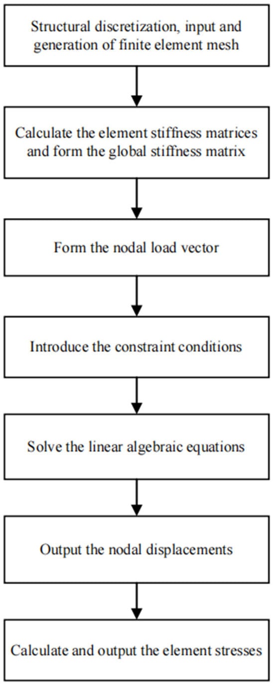
Figure 1.
The internal process of the finite element solver.
In this study, the finite element calculations were performed using the multiphysics coupling analysis software COMSOL Multiphysics 6.3, and the workflow for band structure calculation with this software is as follows: first, a geometric model is constructed and solution domain parameters are defined, which is consistent with conventional finite element calculations; second, boundary conditions are specified. In the model shown in Figure 2, the periodic boundaries are distributed along the x-axis, and based on Bloch theory, the displacement vector follows the following rule:
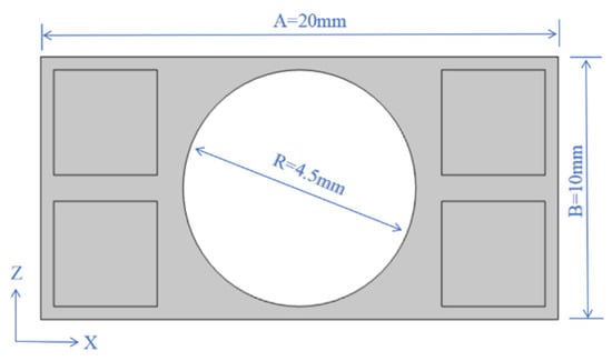
Figure 2.
The geometric structure of the initially proposed phononic crystal plate.
In Equation (1), denotes the wave vector along the X-direction, with . Free boundary conditions are applied to the upper and lower boundaries of the thin plate. Subsequently, meshing is conducted: the unit cell in this model is divided using triangular meshes, each containing 3 nodes and two degrees of freedom (i.e., and ), and the corresponding finite element model is presented in Figure 3. Finally, the calculation is converted into a conventional elastic eigenvalue problem, whose eigenvalues are solved by the linear Equation (2):
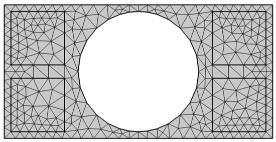
Figure 3.
Finite element calculation model of Scheme 1.
Herein, and represent the stiffness matrix and mass matrix of the system, respectively. The band structure of the periodic structure can be obtained by scanning the wave vector within the first Brillouin zone.
2.2. Structural Design
To achieve a sufficiently low and wide bandgap frequency range, aluminum, lead, epoxy resin, and organic glass were selected as the most suitable materials for further investigation and optimization. The key parameters of these four materials are listed in Table 1. For automotive phononic crystal plate structures, a common design strategy is to adopt low-density materials as the matrix while embedding high-density metals within it. As reported in [], this configuration not only reduces the overall weight of the plate but also ensures effective vibration isolation. The geometric structure adopted in this study is shown in Figure 2, where four square regions are symmetrically arranged around the scatterer and filled with high-density metals []. This periodic arrangement yields a distinct bandgap effect while realizing the harmonious integration of lightweight design, vibration isolation, and sound insulation [].

Table 1.
Material parameters.
The rectangular matrix of the proposed geometric structure has a length of and a width of . A cavity with a radius of is placed at the center, and four square regions with a side length of are symmetrically arranged around it to accommodate high-density metal inserts.
Two metallic materials (aluminum and lead) and two non-metallic materials (epoxy resin and plexiglass) were selected, and a systematic combination strategy was adopted. Epoxy resin and plexiglass were used as base materials, while aluminum and lead served as inlays. By pairing them, four distinct combinations were obtained: Combination 1 (epoxy resin + aluminum), Combination 2 (epoxy resin + lead), Combination 3 (plexiglass + aluminum), and Combination 4 (organic glass + lead). The corresponding finite-element models were then constructed using COMSOL Multiphysics, as shown in Figure 3.
2.3. Computational Methods
To analyze the propagation characteristics of elastic waves in periodic phononic crystal structures, the time-harmonic Navier equation is employed []. It is expressed as Equation (3):
where is the displacement vector, represents the angular frequency, represents the gradient, is the Young’s modulus, and is the Poisson’s ratio.
Suppose that the phononic crystal plates are periodically arranged along the x-axis and are assumed to extend infinitely along the y-axis. The Floquet–Bloch boundary condition [] is applied in the x-axis direction, and its expression is given by Equation (4):
where V is the volume of the cell, is the modulus of the displacement vector, and is the complex conjugate of .
The transmission rate of elastic waves is calculated using Formula (6):
where and denote the magnitudes of the displacement vector components at the input and output ends, respectively. The choice of component depends on the propagation direction and polarization of the incident wave, namely whether it is longitudinal or flexural.
Sound Transmission Loss (STL) is a core evaluation index in the fields of acoustics and sound insulation engineering. Its primary function is to quantify the ability of materials, components or structures to block sound transmission. STL provides critical basis for sound insulation design, performance testing and scheme optimization, and its equation can be expressed as:
Among them, and correspond to the input frequency at the inlet and the output frequency at the outlet, respectively. A higher STL value indicates better sound insulation performance of the material or structure.
3. Numerical Results and Discussion
3.1. The Influence of Different Material Combinations on the Band Structures
Using the finite-element method described above, the band structures of the four material combinations were obtained, as shown in Figure 4, Figure 5, Figure 6 and Figure 7. From these results, the first band gap of each structure can be clearly identified.
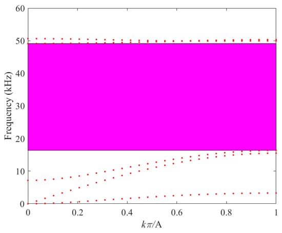
Figure 4.
Band Structure of Scheme 1 (Combination 1).
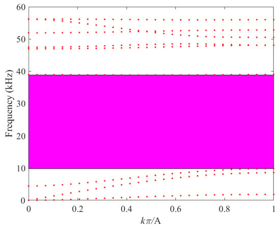
Figure 5.
Band Structure of Scheme 1 (Combination 2).
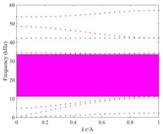
Figure 6.
Band Structure of Scheme 1 (Combination 3).
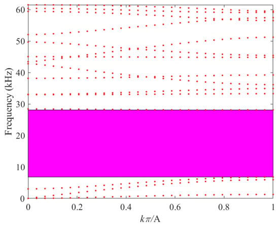
Figure 7.
Band structure of Scheme 1 (Combination 4).
As illustrated in Figure 4, for Combination 1 an obvious band gap is observed between the third and fourth bands. This band gap extends from 16.38 kHz to 49.15 kHz, with a total width of 32.76 kHz.
As depicted in Figure 5, for Combination 2 the first band gap is clearly observed between the third and fourth energy bands. This band gap extends from 9.83 kHz to 38.85 kHz, with a total width of 29.02 kHz.
As illustrated in Figure 6, for Combination 3 a band gap is clearly observed between the third and fourth bands. This band gap extends from 11.21 kHz to 33.55 kHz, with a total width of 22.34 kHz.
As depicted in Figure 7, for Combination 4 a well-defined band gap is clearly observed between the third and fourth energy bands. This band gap extends from 6.80 kHz to 28.11 kHz, with a total width of 21.21 kHz. A comparison of the first band-gap characteristics among the different material combinations is given in Table 2.

Table 2.
Comparison of different material combinations.
As shown in Table 2, the choice of matrix material has a significant influence on the band structure. Among the four combinations, Combination 1 exhibits the largest bandgap width; however, part of its frequency range extends beyond the audible spectrum (20 Hz–20 kHz). In contrast, Combination 4 has the lowest starting and ending frequencies, and within the audible range it provides the widest bandgap. Thus, Combination 4 (organic glass + lead) is identified as the optimal choice.
Organic glass, serving as the base material, not only meets the lightweight requirements of the automotive industry but is also easy to process and relatively inexpensive. Therefore, Combination 4 in Scheme 1 is well suited for the fabrication of phononic crystal plates for automotive applications. In subsequent studies related to Scheme 1, the materials of Combination 4 will be consistently adopted.
3.2. The Influence of Geometric Shape of High-Density Inlays on the Band Structures
The geometric parameters of high-density inlays represent a critical factor in determining the band gap of phononic crystals []. By adjusting the inlay shape, the width, position, and characteristics of the band gap can be effectively tailored. The following section provides a detailed analysis of the effects of three commonly used shapes—square, circular, and rectangular—on the band gap of phononic crystals, based on Combination 4 described above.
The situation of the square scatterer structure () has been discussed earlier as shown in Figure 7.
The influence of the circular inlay on the band structure is shown in Figure 8. Note that the radius and area of the circular inlay are equivalent to those of the square inlay. As illustrated in Figure 8, a well-defined band gap is observed between the third and fourth bands. This band gap starts at 6.89 kHz and ends at 28.12 kHz, yielding a width of 21.23 kHz.
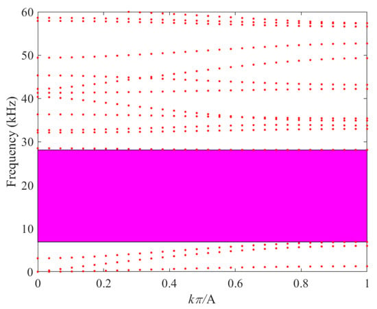
Figure 8.
Band structure of the circular inlaid case.
The influence of the rectangular inlay on the band structure is shown in Figure 9. The rectangular inclusion has a length of and a width of , with an area equivalent to that of the square inclusion. Notably, a distinct band gap is observed between the third and fourth bands, ranging from 6.29 kHz to 22.03 kHz, with a total width of 15.74 kHz. Furthermore, a systematic comparison of the band-gap characteristics of the three aforementioned structures is presented in Table 3.
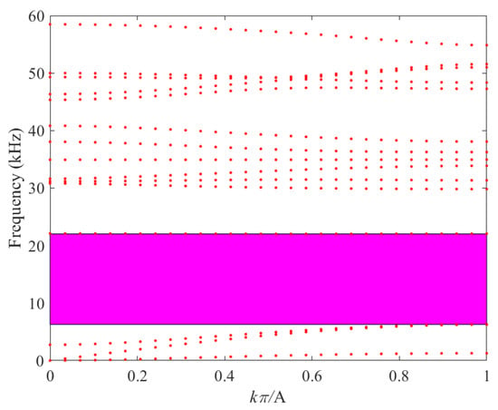
Figure 9.
Band structure of the rectangular inlaid case.

Table 3.
Comparison of different mosaic shapes.
As shown in Table 3, when the high-density inclusions have the same area, variations in geometric shape still exert a significant influence on the band gap characteristics of phononic crystals. Within the frequency range of 0.02–20 kHz, rectangular inclusions provide a noticeably broader effective band gap compared with square and circular inclusions. This result highlights the importance of geometric configuration in optimizing band gap properties. Therefore, the subsequent analysis will further investigate the effect of the volume fraction of rectangular inclusions on the band gap performance of phononic crystals.
3.3. The Influence of the Cross-Sectional Area of High-Density Mosaics on the Band Structures
An increase in the volume fraction of high-density inclusions leads to significant changes in both the effective density and elastic modulus of the composite material. These changes directly affect the propagation velocity of elastic waves []. According to elastic wave theory, wave velocity is inversely proportional to the square root of the material’s density and directly proportional to the square root of its elastic modulus []. As the volume fraction of high-density inclusions such as lead and aluminum increases, the overall density of the composite rises, thereby reducing the velocity of elastic waves. This reduction not only broadens the band-gap width of the phononic crystal but also shifts the band gap toward lower frequencies.
The case where the rectangular inlay has a cross-sectional area of S = 16 mm2 (Figure 9) has already been analyzed. In the following section, the band-gap characteristics corresponding to cross-sectional areas of S = 12 mm2, S = 8 mm2, and S = 4 mm2 will be examined.
As evident from Figure 9, Figure 10, Figure 11 and Figure 12, a distinct band gap is observable between the third and fourth bands across all four proposed schemes. Specifically, in Scheme 2, the band gap initiates at a frequency of 6.86 kHz and terminates at 22.68 kHz, resulting in a band-gap width of 15.82 kHz. For Scheme 3, the band gap commences at 7.69 kHz and concludes at 24.13 kHz, with a band-gap width that attains 16.44 kHz. In the case of Scheme 4, the band gap begins at 9.06 kHz and ends at 27.22 kHz, yielding a band-gap width of 18.16 kHz. A comprehensive comparison of the band structures among these four schemes is presented in Table 4.
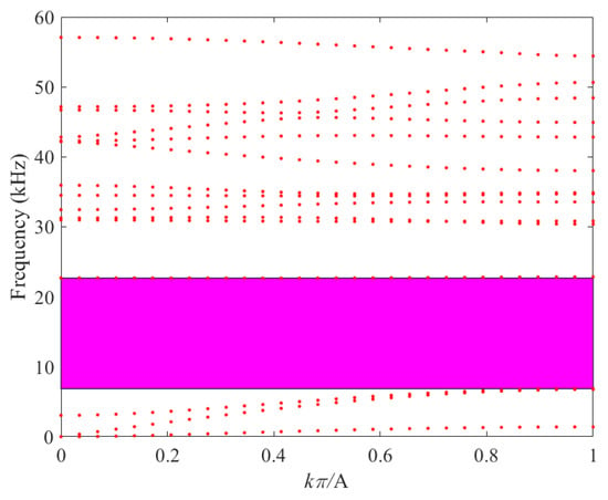
Figure 10.
Band structure with cross-sectional area S = 12 mm2.
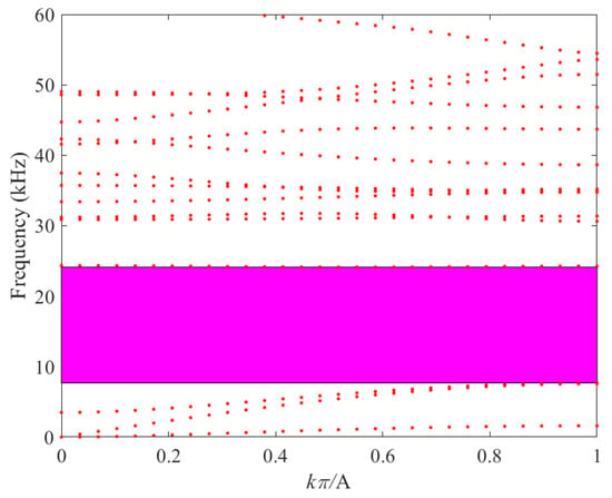
Figure 11.
Band structure with cross-sectional area S = 8 mm2.
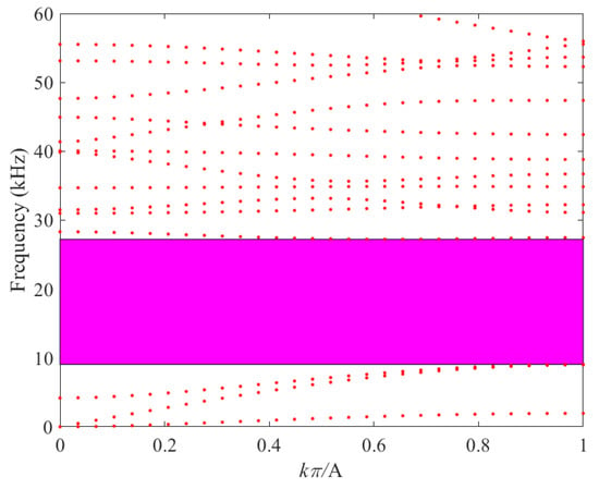
Figure 12.
Band structure with cross-sectional area S = 4 mm2.

Table 4.
Comparison of different cross-sectional areas.
As presented in Table 4, it is evident that the termination frequencies of all four proposed schemes surpass the upper-bound value of 20 kHz. Notably, Scheme 1 exhibits the lowest starting frequency among them. Consequently, Scheme 1 demonstrates the broadest effective bandgap and, relatively speaking, the most favorable performance outcome.
Based on these observations, the following conclusion can be drawn: An increase in the volume fraction of the high-density mosaic component leads to a reduction in the frequency of the phononic crystal and an expansion of the effective bandgap. This conclusion aligns precisely with the theoretical hypothesis put forward in the preceding text. As presented in Table 4, the termination frequencies of all four proposed schemes exceed 20 kHz. Among them, Scheme 1 (16 mm2) has the lowest starting frequency, resulting in the broadest effective band gap and the best overall performance. These results indicate that increasing the volume fraction of the high-density mosaic component lowers the band-gap frequency of the phononic crystal while simultaneously broadening the effective band gap. This finding is consistent with the theoretical hypothesis discussed earlier.
In summary, the phononic crystal plate structure with optimal performance selected to date is illustrated in Figure 13: a rectangular phononic crystal plate with a length of A = 20 mm and a height of B = 10 mm serves as the matrix, and four identical rectangular inclusions each with an area of S = 16 mm2 are embedded in it. The matrix material is organic glass, while the inclusion material is lead.
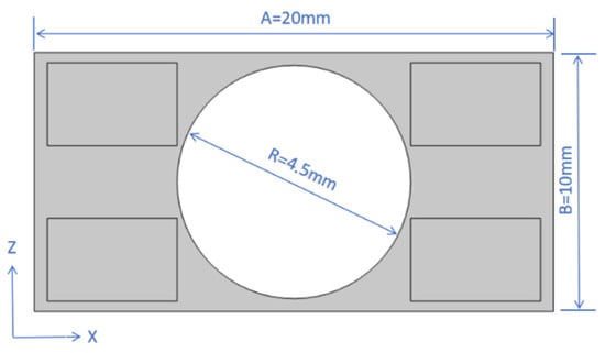
Figure 13.
The geometric structure of the optimally selected phononic crystal plate.
3.4. The Influence of Finite Element Method (FEM) Element Size on Band Structures
To verify the accuracy and reliability of the aforementioned data when using the finite element method (FEM) for analysis, a comparative analysis was conducted between the conventional element size of the triangular elements currently employed and the element sizes after coarsening or refinement, respectively. The FEM calculation model under the conventional size is illustrated in Figure 14, the parameters of the three types of elements are presented in Table 5, and the band gap results obtained from parametric scanning of the optimally selected phononic crystal plate structure using COMSOL Multiphysics software are listed in Table 6.
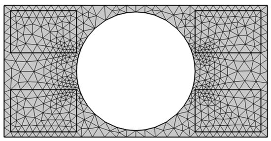
Figure 14.
Finite element calculation model of the optimally selected phononic crystal plate structure.

Table 5.
The parameters of the three types of elements.

Table 6.
Comparison of different element size.
As can be seen from the data in Table 6, under the conditions of refined, conventional, and coarsened element sizes, the initial frequencies are 6.288 kHz, 6.286 kHz, and 6.292 kHz, respectively; the cutoff frequencies are 22.037 kHz, 22.033 kHz, and 22.041 kHz, respectively; and the band gap widths are 15.749 kHz, 15.745 kHz, and 15.748 kHz, respectively. Within the range of 20 Hz to 20 kHz, although the effective band gap under the conventional size is relatively wider, the differences in initial frequency, cutoff frequency, and band gap width among the three sizes are extremely small. The extremely small discrepancies observed in the bandgap characteristics across the three mesh configurations confirm the numerical stability and mesh independence of the finite element model. This mesh convergence study serves as a rigorous numerical validation of the model’s reliability for predicting the band structure of the proposed phononic crystal plate. Consequently, the results obtained with the conventional mesh size are deemed accurate and trustworthy for subsequent performance evaluation and engineering analysis.
3.5. The Mechanisms of the Band Gap Opening
The bandgap in phononic crystal plates essentially involves elastic waves (especially dominant Lamb waves in thin plates) losing propagation ability in specific frequencies, caused by scattering, interference, and energy localization under coupled periodic structures and material parameters. Its formation mechanisms lie in synergistic material parameter mismatch and periodic structural properties. This study’s optimal structure uses low-density, low-elastic-modulus organic glass as the matrix and high-density, high-elastic-modulus lead as inclusions; their distinct density and elastic modulus mismatch triggers strong reflection, refraction, and multiple scattering at interfaces. Scattered and incident waves superimpose, with destructive interference canceling wave energy, suppressing propagation and laying the groundwork for bandgaps. Comparative analysis of material combinations confirms that material parameter mismatch degree decisively affects bandgap onset frequency and propagation suppression intensity.
Periodic structures’ Bragg scattering and inclusions’ local resonance, as pivotal regulatory mechanisms, collectively underpin the complete physical process of bandgap opening in phononic crystal plates while enhancing and optimizing bandgap characteristics. In this study, the phononic crystal plate adopts a periodic inlay configuration with a lattice period of . When the elastic wave wavelength satisfies (where denotes a positive integer representing the diffraction order), scattered waves from adjacent lattice units undergo coherent superposition, generating a frequency interval that inhibits wave propagation and thus forming the Bragg bandgap. Calculations incorporating the Lamb wave propagation velocity in organic glass and the 20 mm lattice period show Bragg scattering’s characteristic frequency aligns well with the optimized structure’s bandgap onset frequency, confirming Bragg scattering as a dominant mechanism for bandgap opening.
Moreover, lead inclusions in periodic phononic crystal plates form discrete “mass-stiffness resonant units,” with their natural resonant frequency determined by the inclusions’ geometric parameters and intrinsic material properties. When incident wave frequency nears this resonant frequency, inclusions vibrate intensely, dissipate wave energy via internal damping and interface interactions, and localize energy in the inclusion region to block diffusion into the organic glass matrix. Overlap between local resonant and Bragg bandgap frequencies induces a “resonance-scattering coupling effect,” broadening effective bandgap width and enhancing wave attenuation. Adjusting inclusion volume fraction modifies resonant units’ mass distribution, regulates the coupling degree, and ultimately reduces bandgap onset frequency to 6.29 kHz while broadening the bandgap.
4. Vibration and Sound Insulation Performance of Phononic Crystal Plates
4.1. Vibration Isolation Characteristics of Phononic Crystal Plates with Finite Periodicity
When investigating the sound insulation performance of thin plates with periodic structures, it is essential to recognize that the concept of an ideal infinite periodic structure is purely theoretical and cannot be realized in practice. In contrast, the periodic structures used in real-world experiments consist of only a finite number of periods with bounded dimensions []. Nevertheless, when the number of periods is sufficiently large, it is both reasonable and practical to approximate the structure as an infinite-period model for research purposes. Such periodic structures possess a strong capability to impede the propagation of elastic waves. Their vibration insulation performance is commonly evaluated through frequency response functions.
Using the computational model for the transmission characteristics of the periodic thin plate shown in Figure 15 as a case study, the superlattice is composed of organic glass, with air acting as the scatterer. The structure consists of 10 periods and is bounded on both sides by organic glass layers of the same thickness as the superlattice. The excitation point is located at the midpoint of the upper surface at one end of the organic glass matrix, while the receiving point is positioned at the corresponding midpoint on the opposite end. To suppress sound wave reflections, perfectly matched layers (PMLs), also made of organic glass, are attached to both ends of the model.

Figure 15.
Calculation model of transmission characteristics of periodic structure.
The transmission spectrum corresponding to the scenario in Figure 9 is presented in Figure 16. The attenuation reaches −274.89 dB at 17.00 kHz and attains its maximum of −280.66 dB at 19.00 kHz. Within the frequency range of 6.00–30.00 kHz, the transmission spectra show substantial attenuation, indicating that elastic wave propagation along the thin plate is strongly suppressed. Notably, at 22.00 kHz, the attenuation briefly recovers due to the presence of an energy band at 22.03 kHz in Figure 7, leading to relatively lower attenuation at this frequency. This behavior aligns with the bandgap frequency range illustrated in Figure 9, confirming the effectiveness of the transmission characteristics of the finite-period periodic thin plate.
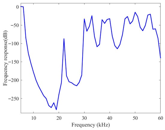
Figure 16.
Transmission spectra of finite-length periodic structure.
4.2. Sound Insulation Performance of Phononic Crystal Plates
In the preceding section, we presented the computational model of the transmission characteristics of periodic structures and analyzed the transmission spectra of finite-length periodic structures. In this section, we evaluate the sound insulation performance of the selected phononic crystal structure [].
Among the structures as shown in Figure 17, dif1, dif4, sq2, and sq3 are all composed of air. Their phononic crystal configurations are identical to that of combination 4, as detailed in Table 2. In the experimental setup, noise is introduced at point A in structure 1 and measured at junction B between dif4 and sq2. Structures sq2 and sq3 serve as Perfectly Matched Layers (PMLs) to eliminate potential interference with the output signal. Using the finite element method described above, together with COMSOL Multiphysics, the Sound Transmission Loss (STL) diagram of the periodic phononic crystal unit structure is obtained, as shown in Figure 18.

Figure 17.
Sound insulation calculation model of periodic phononic crystal structure.
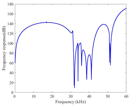
Figure 18.
STL diagram of the periodic phononic crystal unit structure.
As clearly illustrated in Figure 18, a significant sound transmission loss (STL) is evident within the frequency range of 0.01–31.90 kHz. Specifically, at a frequency of 17.00 kHz, the STL attenuation attains a value of 143.99 dB. Moreover, within the frequency span of 5.85–27.91 kHz, the STL consistently remains above 130 dB, indicating outstanding sound-insulation performance. Consequently, it can be reasonably concluded that the phononic crystal unit structure of Scheme 1 (with material selection combination 4) not only demonstrates excellent vibration-isolation capabilities but also exhibits superior sound-insulation performance, thereby effectively meeting the performance demands of phononic crystal plates in the contemporary automotive industry.
4.3. Comparison of the Dispersion Relationship of Flexural Waves with the Theoretical Energy Band Structure
To validate the sound-insulation performance of the band structure shown in Figure 9, the flexural wave components are extracted and analyzed in detail. The main objective is to compare the dispersion relation of the extracted flexural waves with the Sound Transmission Loss (STL) curve of the periodic phononic crystal unit structure presented in Figure 18. The resulting dispersion relation of the flexural waves, obtained through the corresponding procedures, is illustrated in Figure 19.
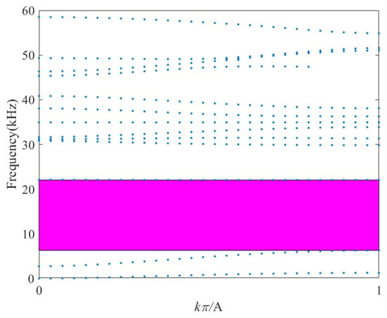
Figure 19.
Flexural wave dispersion relationship diagram.
By comparison, the flexural wave band gap within the specific frequency range shown in Figure 19 is consistent with the first frequency attenuation interval of the Transmission spectra in Figure 16. It is therefore inferred that the energy attenuation within this interval is mainly attributed to the directional band gap along the X-direction. The attenuation interval in the Transmission spectra is wider than the flexural wave band gap, and one possible reason is that other hybrid modes cannot propagate within this frequency range either. This consistency verifies the theoretical prediction of flexural-wave suppression. According to Figure 9, an expected band gap exists within the frequency range of 6.29–22.03 kHz. In Figure 19, the flexural wave dispersion points within this band gap either disappear or exhibit significant amplitude attenuation during transmission; outside the theoretical band gap, the dispersion points in Figure 19 are highly consistent with those in Figure 9. These results indicate that the periodic structure has a strong regulatory effect on flexural wave propagation and confirm that the phononic crystal in the actual structure can effectively suppress flexural waves within the designated frequency range, thereby providing a theoretical basis for its vibration-isolation and sound-insulation performance [].
5. Conclusions
This study systematically investigates how material combinations and structural parameters of automotive phononic crystal plates influence the band gap, aiming to identify the optimal configuration for automotive applications. Four material combinations—aluminum, lead, epoxy resin, and organic glass—were compared. Combination 1 (epoxy resin + aluminum) yields the widest band gap but at a relatively high frequency, whereas Combination 4 (organic glass + lead) provides both a wide band gap and a lower starting frequency. In addition, the use of organic glass as the base material satisfies the lightweight requirements of automotive design, making Combination 4 the most favorable choice. Regarding structural parameter optimization, both the geometry and volume fraction of high-density inclusions play critical roles in band-gap regulation. For a given area, rectangular inclusions produce a wider band gap and lower frequency compared with circular and square ones. Moreover, increasing the volume fraction shifts the band gap toward lower frequencies while further broadening it. Among the tested schemes, Scheme 1—based on Combination 4 with rectangular inserts—achieves the most desirable balance of band-gap width and low-frequency performance.
The principal novelty of this work lies in the identification of this optimal material–structure configuration—comprising an organic glass matrix with rectangular lead inclusions—that effectively integrates low-frequency bandgap formation, broadband vibration isolation, and high sound transmission loss within a lightweight framework. This configuration addresses a significant research gap in the development of multifunctional structures capable of simultaneous vibration and noise control. The proposed design exhibits a complete Lamb wave bandgap spanning 6.29–22.03 kHz, pronounced elastic wave attenuation across 6.00–30.00 kHz, and a sound transmission loss (STL) exceeding 130 dB in the 5.85–27.91 kHz range, demonstrating robust dual functionality in vibration damping and acoustic insulation.
Further comparative analysis reveals a substantial overlap between the vibration-isolation and sound-insulation frequency ranges of the proposed structure. For vibration isolation, the finite-length periodic structure exhibits significant elastic-wave attenuation from 6.00 to 30.00 kHz, with a complete Lamb-wave band gap spanning 6.29–22.03 kHz. For sound insulation, the structure achieves a sound transmission loss (STL) above 130 dB within 5.85–27.91 kHz. Importantly, the core vibration-isolation region (6.29–22.03 kHz Lamb-wave band gap) lies entirely within the sound-insulation range. These results demonstrate that the structure delivers dual vibration–sound control across 6.00–27.91 kHz, with full synchronization in the 6.29–22.03 kHz sub-band.
In this study, the reliability of the finite element method (FEM) was rigorously verified through a mesh convergence analysis, which confirmed the accuracy of the numerical simulations. It was found that when finite element analyses were conducted using different triangular mesh sizes, the differences in the bandgaps of the phononic crystals were extremely small, demonstrating the numerical stability and mesh-independence of the FEM model. In addition, this study also revealed the formation mechanism of the bandgap: in the case of the organic glass-lead combination, the mismatch in material parameters induces wave scattering. The Bragg scattering of the periodic structure and the local resonance of the lead inclusions are coupled with each other, which collectively enable the formation and optimization of the bandgap.
Overall, these findings demonstrate that coordinated optimization of materials and structures can effectively tailor the band-gap properties of phononic crystal plates to meet automotive requirements. This study presents a comprehensive methodology for the practical implementation of automotive phononic crystal plates, covering both material selection and optimized structural design. The proposed framework shows strong potential for advancing vibration- and noise-control technologies in high-speed rail and automotive applications, offering a solid theoretical foundation and practical engineering guidelines for scalable manufacturing and iterative performance improvement.
Author Contributions
Conceptualization, Z.Y. and H.Z. (Hongbo Zhang); methodology, H.Z. (Hongbo Zhang); software, Z.Y.; validation, H.Z. (Haiyang Zhao), Z.Y. and H.Z. (Hongbo Zhang); formal analysis, H.Z. (Haiyang Zhao); investigation, H.Z. (Hongbo Zhang); resources, H.Z. (Haiyang Zhao); data curation, Z.Y.; writing—original draft preparation, Z.Y.; writing—review and editing, H.Z. (Hongbo Zhang); visualization, Z.Y.; supervision, H.Z. (Hongbo Zhang); project administration, H.Z. (Haiyang Zhao); funding acquisition, H.Z. (Haiyang Zhao) All authors have read and agreed to the published version of the manuscript.
Funding
This research was funded by Key R&D Program of Heilongjiang Province, China, grant number JD2023SJ23.
Institutional Review Board Statement
Not applicable.
Informed Consent Statement
Not applicable.
Data Availability Statement
Data are contained within the article.
Conflicts of Interest
The authors declare no conflicts of interest.
References
- Du, X. Research on Phononic Crystals and Noise Reduction Applications of High-Speed Trains. Master’s Thesis, Dalian Jiaotong University, Dalian, China, 2024. [Google Scholar]
- Li, H. Research on Low-frequency Sound Insulation Performance of High-Speed Train Composite Floor Structure Based on Phononic Crystals. Master’s Thesis, Lanzhou Jiaotong University, Lanzhou, China, 2023. [Google Scholar]
- Li, H.; Cao, X.; Shi, G.; Zhang, X.; Song, G.; Zhang, X. Research on Sound Insulation of Floor Support Layer for High-Speed Trains Based on Phononic Crystals. Noise Vib. Control. 2024, 44, 220–225+233. [Google Scholar]
- Fan, H. Research on Band Gap Optimization of Two-Dimensional Phononic Crystals. Master’s Thesis, Chang’an University, Xi’an, China, 2021. [Google Scholar]
- Liu, W. Research on the Design of Novel Phononic Crystal Structures and Control of Low-Frequency Vibration Noise. Master’s Thesis, Chongqing Jiaotong University, Chongqing, China, 2023. [Google Scholar]
- Liu, W.; He, Z.; Cao, Y.; Xiang, Y.; Wang, C. Phononic Crystal Design and Experiment for Vibration and Noise Control of Automotive Compressors. Chin. J. Appl. Acoust. 2024, 43, 488–497. [Google Scholar]
- Vasseur, J.O.; Deymier, P.A.; Djafari-Rouhani, B.; Pennec, Y.; Hladky-Hennion, A.C. Absolute forbidden bands and waveguiding in two-dimensional phononicic crystal plates. Phys. Rev. B Condens. Matter Mater. Phys. 2008, 77, 085415. [Google Scholar] [CrossRef]
- Li, S.; Chen, T.; Wang, X.; Xi, Y. Lamb waves propagation in a novel metal-matrix phononicic crystals plate. Mod. Phys. Lett. B 2016, 30, 1650338. [Google Scholar] [CrossRef]
- Fredianelli, L.; Del Pizzo, L.G.; Licitra, G. Recent developments in sonic crystals as barriers for road traffic noise mitigation. Environments 2019, 6, 14. [Google Scholar] [CrossRef]
- Ouisse, M.; Butaud, P.; Foltête, E.; Chevallier, G. On the use of thermomechanical couplings for the design of adaptive structures. In Active and Passive Smart Structures and Integrated Systems XVI; SPIE: Bellingham, WA, USA, 2022; Volume 12043; p. 1204302. [Google Scholar]
- Liao, Y.; Huang, H.; Chang, G.; Luo, D.; Xu, C.; Wu, Y.; Tang, J. Research on low-frequency noise control of automobiles based on acoustic metamaterial. Materials 2022, 15, 3261. [Google Scholar] [CrossRef]
- Lemkalli, B.; Tugut, O.T.; Ji, Q.; Craster, R.; Guenneau, S.; Kadic, M.; Bizzaglia, C.; Ungureanu, B. Controlling the propagation of flexural elastic waves with ceramic metatiles. Int. J. Mech. Sci. 2025, 302, 110520. [Google Scholar] [CrossRef]
- Xia, Y. Research on Sound Insulation and Noise Reduction Based on Periodic Structure Thin Plates with Side-Embedded Air Columns. Master’s Thesis, Hunan University, Changsha, China, 2013. [Google Scholar]
- Li, S.; Song, J.; Ren, J.; Hou, B. Research on Low-frequency Band Gap Characteristics of phononic Crystals of Functionally Graded Materials. Noise Vib. Control. 2024, 44, 75–81. [Google Scholar]
- Zhang, M.; Wen, X.; Sun, X.; Liu, X.; Song, T.; Liu, Z. Research on ultra-wide Bandgap and Tunability of Composite Column Local Resonance phononic crystals. Noise Vib. Control. 2024, 44, 96–102. [Google Scholar]
- Zhao, Y. Research on Intelligent Methods for Phononic Crystal Bandgap with Uncertain Factors. Master’s Thesis, Jilin University, Changchun, China, 2024. [Google Scholar]
- Sun, y. Research on Vibration and Noise Reduction Performance of Ceramic Ball/Elastomer Phononic Crystal Plates. Master’s Thesis, Jiangsu University of Science and Technology, Zhenjiang, China, 2024. [Google Scholar]
- Song, G. Research on Bandgap Characteristics and Noise Reduction Performance of Phononic Crystal Type Sound Barriers for Rail Transit. Master’s Thesis, Lanzhou Jiaotong University, Lanzhou, China, 2023. [Google Scholar]
- Wei, C. Research on Vibration and Noise Control Method of Gearbox Based on Phononic Crystal Characteristics. Master’s Thesis, Chongqing Jiaotong University, Chongqing, China, 2023. [Google Scholar]
- Xing, Y.; Zhang, B.; Zhang, Y.; Pan, Y.; Song, J.; Wang, M. Research on the Bandgap Characteristics of a Novel dual-oscillator phononic Crystal. Noise Vib. Control. 2023, 43, 51–57. [Google Scholar]
- Yang, Q. Research on Vibration Isolation Performance of Vibration Isolation System Based on Phononic Crystal Bandgap Characteristics. Master’s Thesis, Wuhan University of Technology, Wuhan, China, 2023. [Google Scholar]
- Qin, X.; Ni, A.; Chen, Z.; Ma, B.; Meng, F. Design and Noise Reduction Performance Test of phononic Crystal Sound Barrier with Resonance Mechanism. China Environ. Sci. 2022, 42, 474–482. [Google Scholar]
Disclaimer/Publisher’s Note: The statements, opinions and data contained in all publications are solely those of the individual author(s) and contributor(s) and not of MDPI and/or the editor(s). MDPI and/or the editor(s) disclaim responsibility for any injury to people or property resulting from any ideas, methods, instructions or products referred to in the content. |
© 2025 by the authors. Licensee MDPI, Basel, Switzerland. This article is an open access article distributed under the terms and conditions of the Creative Commons Attribution (CC BY) license (https://creativecommons.org/licenses/by/4.0/).