Abstract
Concealed conductive connections between a transmission tower’s grounding grid and its foundation can cause a portion of the lightning strike current to enter the foundation and concentrate at the concealed conduction locations, thereby increasing the risk of foundation deterioration. To investigate the impact characteristics of such currents on the foundation under this operating condition, this study first establishes an electro-thermal-mechanical coupled finite-element model of the tower foundation that incorporates a subsurface concealed conductive loop, and compares the foundation’s temperature rise and mechanical characteristics under lightning currents and under power-frequency follow currents. The results indicate that power-frequency follow current poses a substantially greater hazard to the foundation than lightning current. Based on similarity theory, scaling laws for the foundation subjected to the impacts of power-frequency follow current are then derived. Considering that the intrinsic electro-thermal properties of the foundation cannot be altered in the scaled model, a parameter correction method is proposed according to quasi-similarity criteria. The corrected scaled-model results are compared with those of the prototype in simulation, and principal indicators exhibit deviations within 3%. A physical scaled model was subsequently designed and fabricated for impact testing, and ultrasonic inspection was used to assess potential damage in the concealed conduction region. The results show that under the action of power-frequency follow currents, the maximum temperature at the concealed conductive region reaches 124 °C, with deviations of 2.83% from the prototype simulation and 3.58% from the scaled-model simulation. The tower foundation was subjected to 20 power-frequency follow current impacts. After each impact and subsequent cooling, ultrasonic measurements of wave propagation velocity at the concealed conduction center decreased from 3.797 km/s to 3.571 km/s. The observed reduction in wave speed indicates a loss of local concrete structural integrity and suggests the risk of performance degradation and initiation of microcracks. These findings provide a reference basis for assessing the safety of tower foundations under concealed conduction conditions.
1. Introduction
The grounding grid of transmission line towers serves as a critical support structure for the power grid, and reliable grounding is essential to ensure the safe and stable operation of the power system [,,]. Accordingly, periodic measurement of tower grounding resistance and routine inspection of tower foundations have become important measures to guarantee the reliable operation of transmission lines [,,]. In recent years, field maintenance of transmission towers has frequently revealed the phenomenon of concealed conduction between the grounding grid and the tower foundation; that is, unintended conductive connections exist among the tower body, the foundation reinforcement cage, and the grounding grid. This concealed conduction provides a current dissipation path along the tower–foundation reinforcement cage–grounding grid during lightning strikes or short-circuit faults, leading to uneven current distribution and localized energy concentration []. Under the cumulative effects of repeated lightning currents and power-frequency follow current impacts, the tower foundation may undergo deterioration, with the initiation of microcracks or even structural damage, thereby posing potential safety risks. Therefore, an in-depth investigation of the impact damage characteristics of tower foundations under concealed conduction conditions is of great significance for ensuring the long-term safe operation of transmission lines
With respect to the damage characteristics of concrete, relevant researchers have conducted numerous studies on concrete fatigue damage, impact-load-induced damage, and other aspects [,,]. Saqif et al. [] experimentally investigated the compressive behavior of ultra-high-performance concrete with ultra-high compressive strength under monotonic and cyclic uniaxial compression and proposed a one-dimensional plastic damage constitutive model capable of simulating cyclic compression-induced damage in concrete. Jin et al. [], using mesoscale numerical analysis, examined the damage zones of ordinary concrete at elevated temperatures and found that the damage becomes more concentrated at elevated temperatures compared with normal conditions, revealing the interaction between the strain-rate effect and the temperature-induced degradation effect in concrete. Cui et al. [] conducted dynamic Brazilian disk splitting tests on specimens of different concrete types and analyzed the fracture processes and crack propagation patterns of various fiber-reinforced concretes. Nie et al. [] introduced damage accumulation effects within an elastoplastic finite-element framework and implemented a UMAT in LS-DYNA to analyze how cumulative damage influences the dynamic response and collapse process of transmission towers. They pointed out that by classifying the damage at the component and segment levels, the degree of damage in each tower segment can be quantitatively evaluated. Gidrão et al. [] studied damage evolution in normal- and high-strength concretes through cyclic loading and acoustic measurements, reporting changes in internal damping ratio and dynamic elastic modulus that provide experimental evidence for quantifying dynamic damage under impact and cyclic actions. Krentowski [] systematically analyzed the failure mechanisms of concrete structures in long-term service under various adverse conditions, such as explosions, fire, and aggressive environments, and proposed repair measures and engineering recommendations tailored to different damage types, thereby providing valuable practical guidance for safety assessment and strengthening decisions. Dixit et al. [] employed embedded piezoelectric transducers to monitor impact- and fatigue-induced damage in concrete, extracted equivalent damping, stiffness, and mass parameters using the electro-mechanical impedance technique, and demonstrated that PZT signatures exhibit clear, damage-dependent changes that can be used to predict residual service life. Regarding the current dispersion and damage characteristics of concrete under impulse current, relevant scholars have also conducted in-depth studies. Wang et al. [] used COMSOL (https://cn.comsol.com/, accessed on 10 June 2025) to investigate the current diffusion characteristics and resistance reduction efficiency of concrete pile foundations in wind turbine systems. They analyzed the influence of different soil resistivities on grounding performance and proposed that applying flexible graphite composite grounding materials on the surface is more effective for reducing resistance in wind turbine foundations. Zhang et al. [] studied the thermal characteristics of conductive concrete foundations of towers under continuous lightning strikes, considering soil ionization, spark effects, and cumulative effects. They pointed out that when the number of continuous lightning strikes exceeds three, the temperature can reach 300 °C, which may cause structural damage to the foundation, suggesting that reducing grounding resistance and enhancing the current diffusion capacity of the grounding network are necessary. Tian et al. [] performed a comparative analysis of ordinary and conductive concrete under lightning current impact, revealing that cracks are likely to occur in the main column region of the foundation during the electro-thermal damage coupling process of lightning discharge. However, although these studies have advanced understanding of concrete impact behavior for transmission towers, they have not sufficiently considered the effects of high-amplitude currents concentrated at concealed conduction locations when the tower grounding grid and foundation are electrically connected. Consequently, building upon existing research, this study combines simulation and scaled experiments to investigate in depth the impact characteristics of high-amplitude currents concentrated at concealed conduction locations within the tower foundation.
This study addresses the engineering problem of localized heating and subsequent electro-thermal-mechanical damage in transmission tower foundations caused by current concentration at concealed conductive paths between the foundation and the grounding grid. A parameter correction method for scaled experiments is proposed and validated to accurately reproduce the prototype’s localized heating and mechanical responses under geometric scaling. Based on finite-element simulations, the current concentration and temperature rise responses in the concealed conduction region under lightning impulses and power-frequency follow currents were analyzed, confirming that the latter poses a higher risk due to sustained Joule-heat accumulation. Considering that intrinsic material parameters such as concrete electrical conductivity and thermal conductivity cannot be proportionally scaled, a current amplitude correction approach based on quasi-similarity criteria is introduced to reproduce the coupled electro-thermal-mechanical behavior of the prototype in the scaled model. An experimental platform for power-frequency follow current impact testing was designed and constructed, and multiple impact tests were performed on the scaled foundation model. By combining real-time temperature monitoring with ultrasonic nondestructive testing and comparing changes in wave velocity and waveform, the study provides a detailed analysis of concrete property degradation at the concealed conduction site.
2. Finite-Element Model Setup
This article establishes a finite-element simulation model for a concrete tower foundation. The main column measures 1200 mm × 1200 mm × 2000 mm. The grounding grid is made of a flexible graphite composite and is buried at a depth of 0.8 m. Inside the foundation, eighteen vertical reinforcement bars with a diameter of 22 mm are distributed in the vertical direction, and six horizontal stirrups with a diameter of 20 mm are evenly arranged in the horizontal direction. The temperature at the foundation surface and at the far field of the soil is fixed at 20 °C. Convective heat transfer between the foundation surface and the ambient air is imposed, with a heat transfer coefficient of h = 10 W/·(m−2·K−1). Figure 1a illustrates the multiphysics simulation model of the tower foundation and grounding network, where the red dashed line indicates the concealed conductive loop. Figure 1b presents a schematic diagram of the internal structure of the tower foundation with the concealed conductive loop.
Figure 1.
(a) Schematic diagram of the tower foundation and grounding network; (b) schematic diagram of the internal structure of the tower foundation.
Part of the core material parameters used in the simulation model are listed in Table 1; all other parameters were set according to the built-in material library.
Table 1.
Physical parameters of materials in the prototype model.
For the electromagnetic/thermal-mechanical impact simulations, the standard 2.6/50 μs lightning current waveform was selected:
In the governing expression, I0 denotes the peak current in kA, k is the peak correction factor, and α and β are the time constants for current decay and rise, respectively.
To investigate the influence of concealed conduction on the current dispersion of transmission tower foundations, a shunt coefficient η is defined to quantitatively describe the current distribution.
In the equation, ηf represents the shunt coefficient of the tower foundation with concealed conduction, ηc denotes the shunt coefficient of the concealed conduction loop, Is is the amplitude of the injected system current, If is the amplitude of the current flowing into the tower foundation with concealed conduction, and Ic is the amplitude of the actual current flowing through the concealed conduction path.
In the baseline foundation model, a concealed conductive loop was introduced, resulting in two parallel leakage paths: the earthing down-lead and the concealed loop. A soil resistivity of 500 Ω·m was adopted for the calculations. Reference [] presents a detailed numerical analysis of the distributions of lightning currents with a duration of 300 μs and peak values ranging from 40 kA to 120 kA, and of power-frequency follow currents with a duration of 0.54 s and amplitudes ranging from 3.5 kA to 9.9 kA. Reference [] employed ATP (https://atp-emtp.org/, accessed on 18 May 2025) software to calculate the grounding resistance and current dispersion characteristics of tower foundations under continuous lightning strike currents. Based on the above literature analysis, this study selects a lightning current with a peak amplitude of 120 kA and a power-frequency follow current with an amplitude of 9.4 kA. The resulting dispersion coefficient ηf is calculated to be 61.71%, indicating that the corresponding current flowing into the concealed conductive tower foundation is 74.05 kA for the lightning current and 5.8 kA for the power-frequency follow current. Furthermore, the dispersion coefficients ηc under lightning current and power-frequency follow current are 62.42% and 65.74%, respectively. These results demonstrate that for tower foundations with concealed conductive paths, only about 35% of the discharge current flows into the grounding grid through the earthing down-lead, while the remaining portion is dispersed through the concealed conductive path within the foundation. Therefore, this study focuses on a detailed analysis of concealed conductive tower foundations, with simulation parameters set to a lightning current of 74.05 kA lasting 100 μs and a power-frequency follow current of 5.8 kA lasting 0.56 s. The flow chart of the simulation calculation is shown in Figure 2.
Figure 2.
Simulation calculation flowchart.
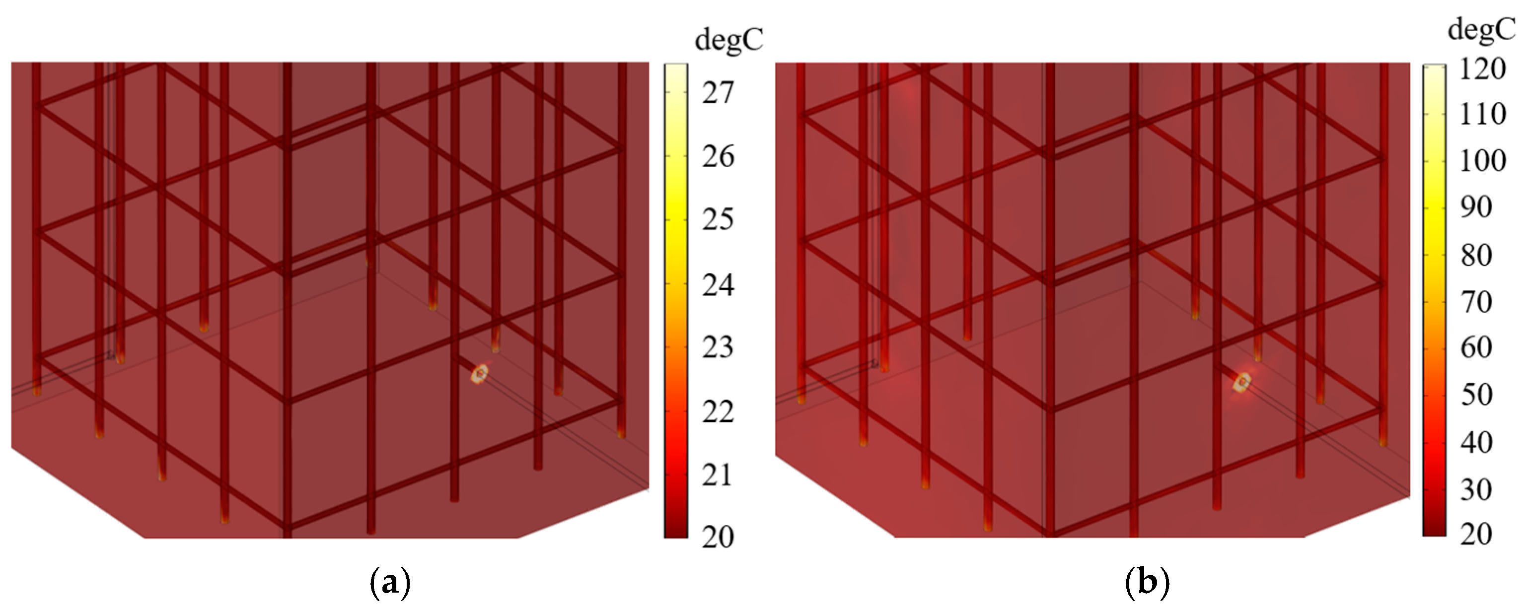
The temperature distribution of the tower foundation is shown in Figure 3. For both current types, the maximum temperature occurs at the concealed conduction site. The peak temperature under lightning current is 27.45 °C, while under power-frequency follow current it reaches 120.59 °C. Hence, the thermal effect induced by the power-frequency follow current is substantially greater than the transient heating caused by lightning current, leading to more pronounced potential damage to the foundation. The electrical and thermo-mechanical responses at the concealed conduction site under different current types are summarized in Table 2.
Figure 3.
(a) Temperature distribution under lightning current; (b) temperature distribution under power-frequency follow current.
Table 2.
Electrical and thermo-mechanical characteristics at the concealed conduction site under different current types.
The results indicate that the stress and displacement levels under power-frequency follow current are approximately 13 times higher than those under lightning current. Such significant superimposed thermo-mechanical effects may lead to local thermal cracking of the concrete, degradation of the bond between steel reinforcement and concrete, and deterioration of the overall material properties, thereby posing a substantial threat to the service safety of the tower foundation. In contrast, although the lightning current exhibits a much higher peak value, its extremely short duration results in relatively limited damage effects. Based on these findings, this study focuses on investigating the impact mechanism of power-frequency follow current on the dynamic response of transmission tower foundations, with the aim of providing theoretical guidance for protective design and service life evaluation in engineering practice.
3. Derivation and Validation of Scaling Relations for the Foundation
3.1. Derivation of Scaling Relations
Similarity theory has been widely used in power-system studies [,]. When a tower foundation concrete is subjected to an impact current, the current tends to concentrate at the concealed conductive location, causing a rapid rise in temperature inside the concrete and generating steep temperature gradients that lead to irreversible property degradation. The principal input parameters considered here are mass M, length L, time T, temperature θ, electric current I, coefficient of thermal expansion α, density ρ, thermal conductivity k, specific heat at constant pressure Cp, electrical conductivity σe, Young’s modulus E, and frequency f. Output parameters include the concrete stress at the conduction site σ, temperature rise ΔT, and displacement δ. According to the Buckingham π theorem, choosing M, L, T, θ, and I as the fundamental physical dimensions allows the dimensions of the remaining quantities to be expressed in terms of these five base dimensions; the resulting dimensional relationships are listed in Table 3.
Table 3.
Dimensional matrix.
To construct dimensionless groups, we select ρ, L, E, Cp, and I as the repeating variables. Their dimensional forms are [ML−3], [L], [ML−1T−2], [L2T−2θ−1], and [I]. A generic dimensionless group can therefore be written in the following form:
In the expression, A is a constant and a, b, c, d, e are the exponents associated with the respective physical quantities. Applying the principle of dimensional homogeneity and equating the powers of the chosen fundamental dimensions for the above expression yields the following system of equations:
Here α1–α5 denote the dimensional exponents of the selected base physical quantities, i.e.,
Solving the coupled systems (4) and (5) yields
According to the Buckingham π theorem,
The logarithmic form for the electrical conductivity σe can be written as
Similarly, nondimensional combinations for other physical quantities (thermal conductivity, thermal expansion coefficient, stress, temperature rise, displacement, etc.) are obtained following the same procedure:
Similarity theory requires geometric, kinematic, and dynamic similarity; hence, each nondimensional group must be identical for the model and the prototype. The similarity ratio of any physical quantity Q between the model and the prototype is denoted by
Subscripts m and p denote the scaled model and the prototype, respectively. For the similarity ratio of the dimensionless group associated with the thermal expansion coefficient, we obtain
From which it follows that the similarity ratio for the thermal expansion coefficient is
Applying the derived similarity criteria sequentially yields the similarity ratios for other parameters such as the thermal conductivity; the complete set of similarity relations for the scaled model is summarized in Table 4.
Table 4.
Similarity ratios.
3.2. Correction of the Scaling Relations
A 1/4-scale model was constructed with the same structural configuration as the prototype. The scaled foundation dimensions are 300 mm × 300 mm × 500 mm; the vertical reinforcement bar diameter is 5.5 mm and the stirrup diameter is 5 mm. The scaled model is composed of the same material types as the prototype, and its material parameters are initially obtained via the similarity relations and scaling formulae:
The geometric scale factor of the model is denoted by βL. From the similarity derivation, the thermal conductivity of the scaled model should be βL times that of the prototype, the electrical conductivity should scale as βL−1 of the prototype, and the current frequency should also scale as βL−1. In practice, however, electrical conductivity and thermal conductivity are intrinsic material properties that cannot be adjusted arbitrarily when fabricating the physical model. Similarly, because the experiment employs a mains power supply, the frequency remains fixed at 50 Hz. Consequently, a scaled model constructed strictly according to the similarity relations will exhibit deviations in reproducing the prototype’s electrical behavior; therefore, the corresponding scaling coefficients must be further corrected.
When current flows through the concealed conduction point, localized heating is generated due to the Joule heating effect. The heat generation rate can be expressed as
where J is the current density (A/m2) and E is the electric field intensity (V/m).
The generated heat diffuses through the material via thermal conduction, a process governed by the Fourier number:
Based on the derived similarity ratio relationships, the following correlations for heat generation rate and Fourier number exist between the prototype and the model:
Furthermore, the power source frequency influences the skin depth of the current in the conductor:
According to the similarity ratio relationships, the following can be obtained:
The temperature rise induces thermal expansion in the material, resulting in a strain of
Similarly, the thermal strain of the scaled model satisfies
For the 1/4-scale model, holding the material electrical conductivity, thermal conductivity, and the main frequency constant leads to a temperature rise in the model that is four times that of the prototype. Since concrete damage is primarily induced by thermal stress arising from thermal expansion, other electrical and thermo-mechanical responses are likewise amplified by a factor of four. To ensure that the scaled model can accurately reflect the electrical characteristics of the prototype, the scaling relationship must be corrected. From Equations (15)–(17), the following relationship can be derived:
To minimize the errors introduced by fixed parameters in the scaled experimental model, namely, to ensure that the result of Equation (23) equals 1, either the current duration or the current amplitude can be adjusted. For the 1/4-scale model, the current duration corresponds to one-fourth of that in the prototype. Under otherwise identical conditions, this study chooses to reduce the applied current amplitude to one-eighth of the prototype value, ensuring that the resulting temperature rise accurately reproduces the prototype’s thermal trend. A comparative analysis is then conducted on the simulation model after applying this current amplitude correction.
3.3. Validation of the Scaling Relations
To visually compare the electrical characteristics between the scaled model and the prototype structure, the calculation results from the scaled model, established based on similarity theory, were scaled up according to the derived similarity ratios.
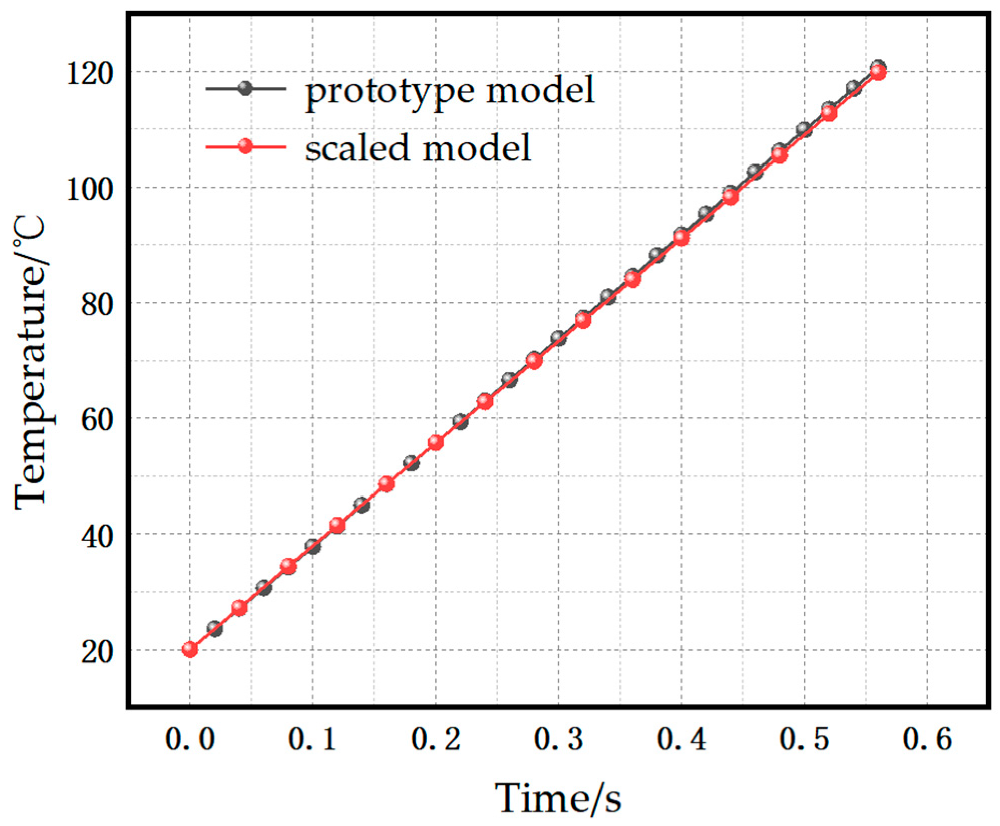
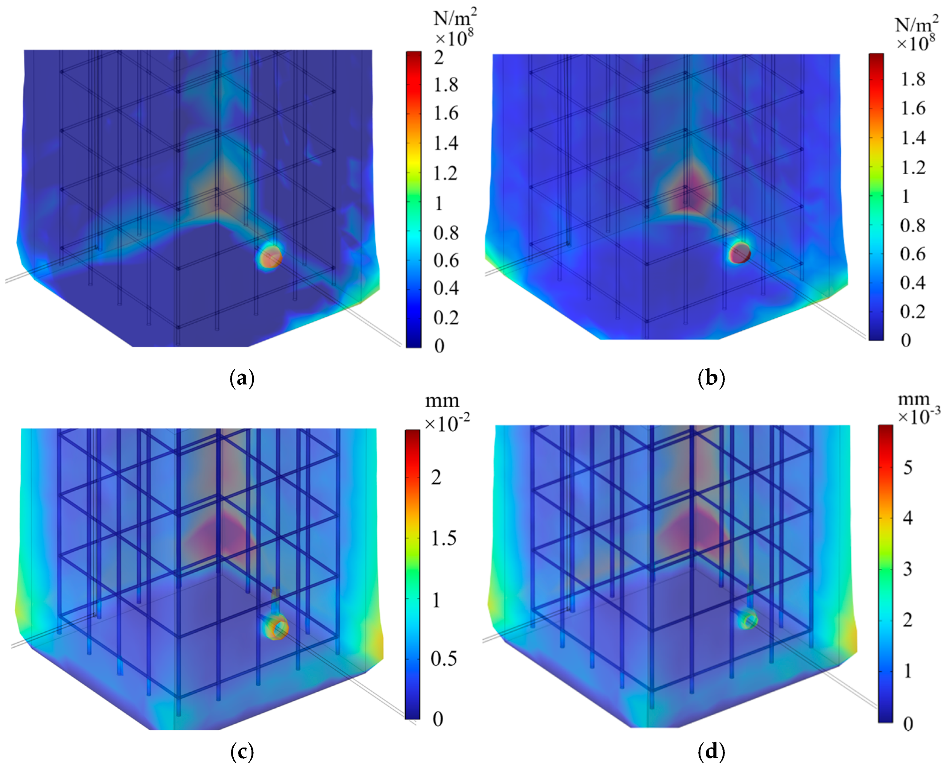
The maximum temperature at the concealed conduction point was 119.71 °C for the scaled model and 120.59 °C for the prototype, resulting in an error of approximately 0.73%. The temperature rise curves of the scaled model and the prototype show good agreement, indicating that the scaled model effectively captures the temperature rise characteristics of the actual prototype. The distributions of thermal stress and displacement for both the prototype and the scaled model are shown in Figure 4.
Figure 4.
Temperature rise curves for the prototype and the scaled model.
The maximum stress at the concealed conduction location in the scaled model was 1.98 × 10⁸ Pa, compared with 2.03 × 10⁸ Pa in the prototype, corresponding to an error of approximately 2.46%. The maximum displacement of the scaled model was 5.83 × 10⁻³ mm, versus 2.40 × 10⁻² mm for the prototype, with an error of about 2.83%. Both the prototype and the scaled model exhibit similar stress and displacement distributions. Due to end effects, the current tends to flow toward the ends of the reinforcement bars; however, because only a single concealed conductive path exists, the current dissipation path is limited, which also induces notable deformation at the base of the foundation.
After correcting the applied current amplitude, the scaled model shows good agreement in temperature response and other electrical characteristics, with errors controlled within 3%. The corrected scaled model can therefore effectively reproduce the electrical behavior of the real structure. Accordingly, a 1/4-scale physical test model was fabricated with the same structural configuration and subjected to power-frequency follow current impact tests for further analysis.
4. Scaled-Model Fabrication and Testing
4.1. Scaled-Model Fabrication
Because the damage caused by power-frequency follow currents is substantially greater than that of lightning currents, an experimental apparatus for investigating foundation impact behavior under power-frequency follow currents was designed and assembled; a schematic of the test rig is shown in Figure 5. The test system comprises an AC power supply, a voltage divider, Rogowski coils, the concrete scaled foundation model, thermocouples for temperature monitoring, and a data-acquisition card. The power source is a 500 A AC generator; loop current and voltage measurements are performed using a Rogowski coil and a voltage divider with ratios of 100:1 and 5000:1, respectively, connected to the acquisition system.
Figure 5.
(a) Stress distribution in the prototype model; (b) stress distribution in the scaled model; (c) displacement distribution in the prototype model; (d) displacement distribution in the scaled model.
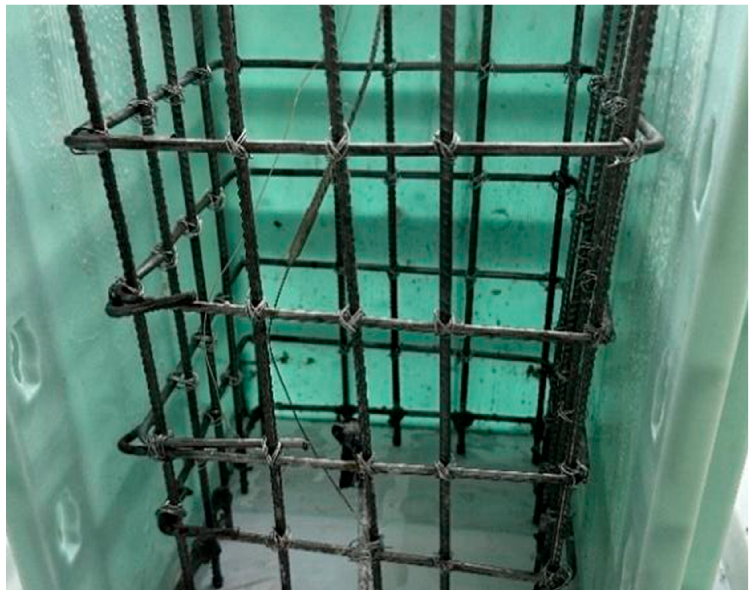
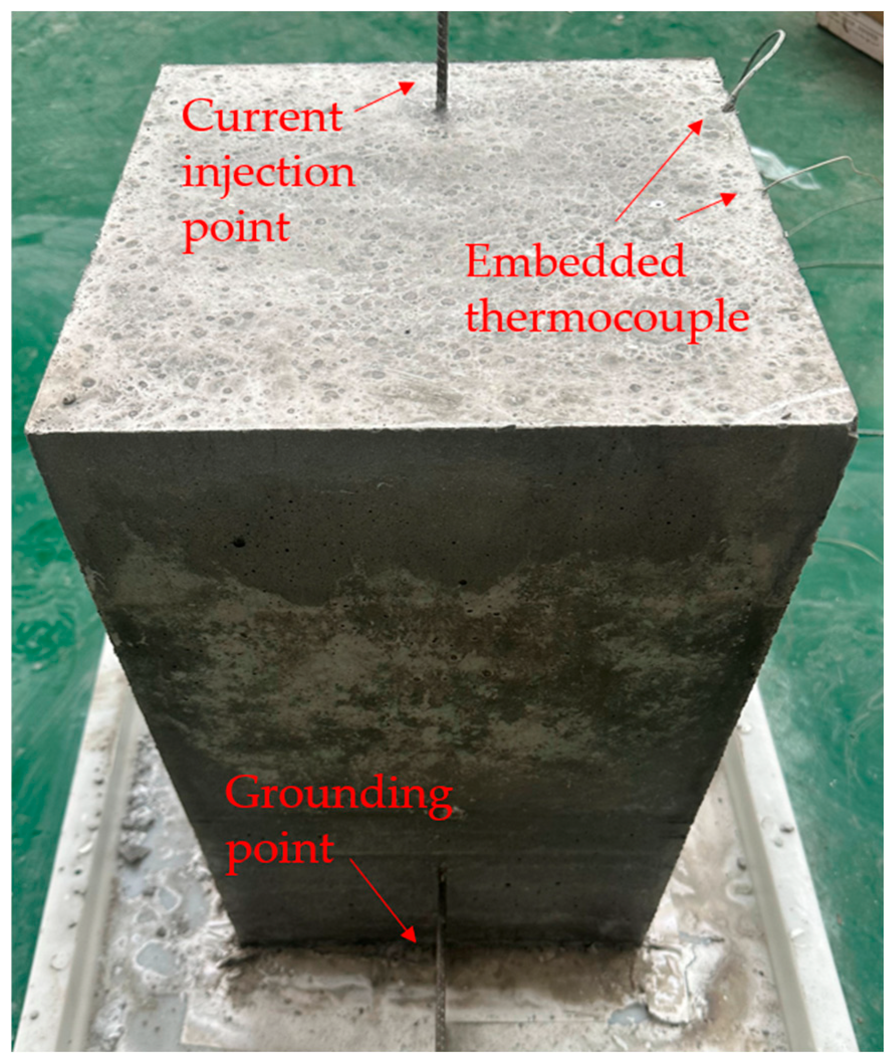
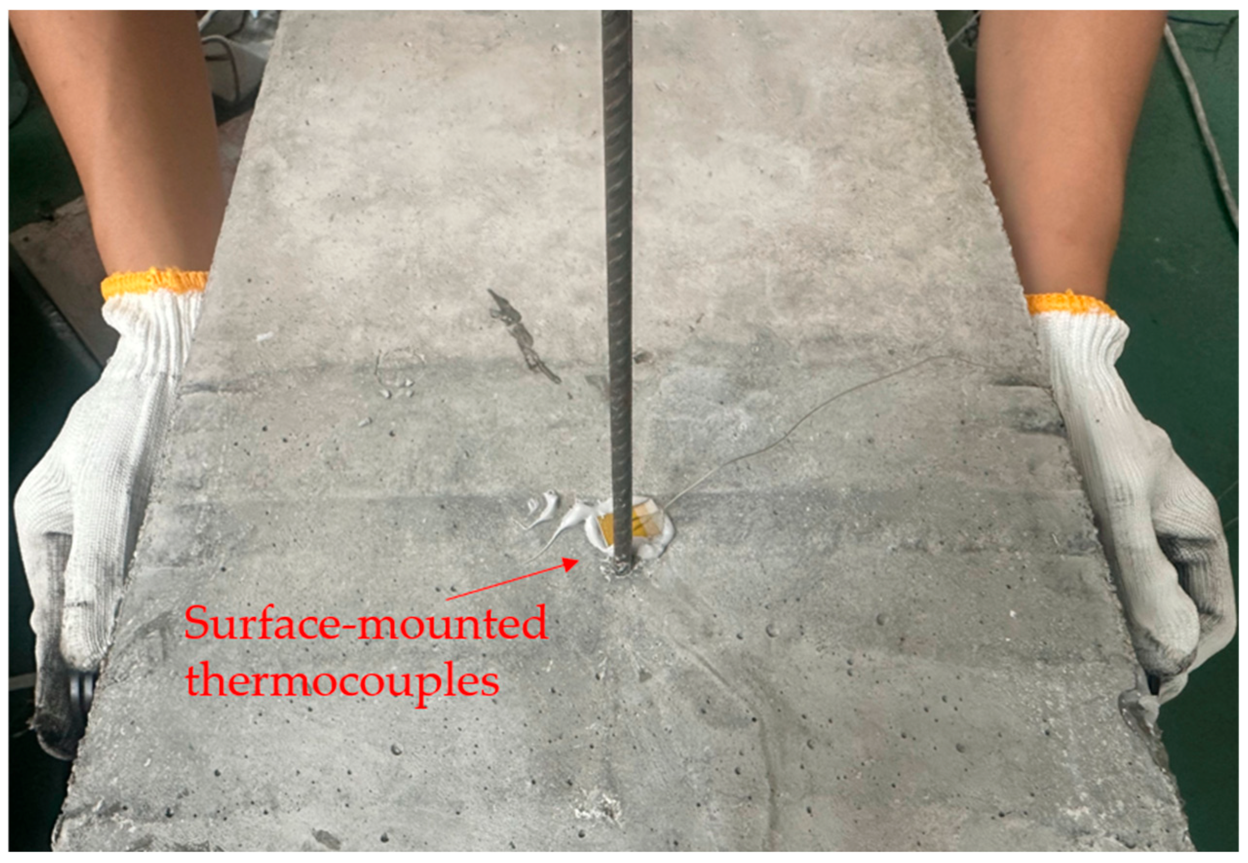
A reinforcement cage was fabricated by tying Ø5.5 mm longitudinal bars and Ø5 mm stirrups, as illustrated in Figure 6. Thermocouple-equipped optical fibers were embedded adjacent to the reinforcement at the concealed conduction location and cast integrally with the concrete; surface-mounted thermocouples were attached to the concrete surface above the concealed conduction site for external temperature monitoring. Approximately 5 cm of exposed rebar was reserved at the concrete surface to serve as the current-injection electrode. The concrete used in the test is C30 ordinary concrete, and the specific mix proportions are shown in Table 5.
Figure 6.
Schematic of the experimental setup.
Table 5.
C30 concrete mix ratio.
After the concrete foundation was cast, it was cured under room-temperature conditions by covering with a plastic film for moisture retention over a period of 28 days. Upon reaching the design strength, the specimens were subjected to testing. Prior to the formal impact tests, nondestructive testing instruments were employed to perform a full-domain scan of the concrete specimens, recording baseline data such as wave velocity, acoustic travel time, and waveform characteristics. Subsequently, the model was mounted on the experimental platform, where a power-frequency current impulse with an amplitude of approximately 0.3 kA and a duration of 1 s was applied. Each impulse was spaced by an interval of 30 min to ensure the specimen fully cooled back to ambient temperature, thereby avoiding thermal accumulation that could interfere with subsequent results. During the test, a data acquisition system continuously recorded the transient temperature variations at each measurement point. After all impact tests were completed, the specimens were scanned again using nondestructive methods. By systematically comparing the changes in wave velocity attenuation, acoustic travel time, and waveform distortion before and after the impacts, the initiation and propagation of internal damage in the concrete were comprehensively evaluated.
Photographs of the cast scaled model are presented in Figure 7. The internal concrete at the grounding point was designated as the concealed conduction center. During fabrication, two thermocouples were tied beside the reinforcement at the concealed conduction center and cast together with the reinforcement cage. After curing, surface thermocouples were attached at the corresponding locations. See schematic in Figure 8.
Figure 7.
Fabrication of the internal reinforcement cage.
Figure 8.
Photograph of the scaled concrete foundation model.
4.2. Experimental Results and Analysis
Common nondestructive techniques for detecting internal defects in concrete include ground-penetrating radar, acoustic emission, impact-echo method, and ultrasonic testing [,,]. In this study, ultrasonic inspection was employed to evaluate the post-impact internal condition. When ultrasonic waves propagate through concrete, they are reflected, refracted, or scattered by voids, lack of compaction, cracks, and other anomalies; the received signals are analyzed to infer the internal structure []. Concu et al. [] obtained UPV maps on a test concrete wall with embedded voids and reported pointwise velocities ranging approximately 2.874–4.540 km/s, mean ≈ 4.210 km/s, with the lowest velocities spatially coincident with the artificial defects, thus demonstrating clear low-velocity zones for defect localization. Complementary controlled cracking tests by Camara et al. [] showed that induced cracks produced measurable UPV reductions on the order of 1.9–3.7%, accompanied by observable waveform attenuation and amplitude decrease. These results demonstrate that ultrasonic testing can identify concrete defects by measuring the wave velocity attenuation and waveform distortion caused by ultrasonic waves passing through the defect. This method is also feasible for detecting structural integrity damage in hidden conductive connections.
Ultrasonic measurements in the present test were performed using an RSM-RCT(B) velocity meter. Nine inspection points were arranged around the concealed conduction location, with point 5 located at the concealed conduction center and the remaining points placed at 50 mm intervals around point 5. The emitter and receiver probes were separated by 300 mm, and petroleum jelly was used as the coupling medium. A schematic of the velocity measurement setup is shown in Figure 8.
The concrete foundation was subjected to twenty AC current impacts of 0.3 kA. After each impact, the specimen was allowed to cool before ultrasonic inspection was performed at the predefined measurement points. The accuracy of ultrasonic testing is influenced by factors such as the coupling between the probe and the specimen, the surface roughness of the specimen, and the inherent uncertainties of the pulse generator and standard attenuator. Therefore, during the testing process, any abnormal data points were remeasured, and the average value obtained from multiple measurements was taken as the final wave velocity result. The variation in each measurement point with increasing impact count is shown in Figure 9.
Figure 9.
Wave velocity measurement schematic.
As the number of impacts increased, a gradual decline in wave velocity was observed across the measurement points, with the most pronounced effect at point 5, the concealed conduction center. The wave velocity at point 5 decreased from an initial 3.797 km/s to 3.571 km/s, a reduction of approximately 5.95%, indicating possible internal performance degradation. Representative pre- and post-test waveforms at point 5 are compared in Figure 10.
Figure 10.
Wave velocity curves at measurement points under multiple impacts.
Waveforms at measurement point 5 before and after the test is shown in Figure 11. Before testing, the waveform signals were relatively stable. Although small fluctuations occurred due to scattering from internal rebar, the main peak was clear and the energy was concentrated, indicating an intact bulk transmission path in the concrete. As the impact tests progressed, waveform fluctuations increased markedly: the main peak amplitude gradually decreased, and multiple secondary small peaks appeared after the main peak. This behavior is consistent with enhanced internal multiple reflections and scattering of the acoustic wave. The reduction in the main peak amplitude indicates that transmitted energy is increasingly dissipated or scattered into non-direct paths; the increase in secondary peaks suggests the emergence of new reflective interfaces—e.g., microcracks, interface debonding, or the generation of air voids/pores—complicating wave propagation paths and reducing transmission efficiency.
Figure 11.
Waveforms at measurement point 5 before and after testing: (a) pre-test waveform; (b) post-test waveform.
At sensor point 5, the wave speed remained at approximately 3.79 km/s during the first five impacts, indicating no obvious internal deterioration of the concrete in the early impact stages. After the sixth impact, however, the wave speed dropped to 3.745 km/s and then exhibited a monotonically decreasing trend with further impacts, reaching 3.571 km/s after the 20th impact. The relative decrease from initial to final state is about 5.95%, which indicates that cumulative current impacts have caused degradation of concrete performance and even present a risk of microcrack initiation.
The preceding simulation analysis yielded maximum temperatures at the concealed conductive location of 120.59 °C for the prototype model and 119.71 °C for the scaled model under power-frequency continuing current. In the experimental continuing current impacts, monitoring data show that the internal concealed conductive location reached a peak temperature of approximately 124 °C—a relative error of 2.83% with respect to the prototype simulation and 3.58% with respect to the scaled-model simulation—thus demonstrating that the scaled model’s continuing-current impact tests can effectively reproduce the electrical-thermal behavior of the actual engineering model. Surface thermocouple monitoring recorded a maximum temperature of about 97.2 °C; the higher internal temperature indicates heat accumulation within the concealed conductive zone and slow dissipation. Such internal overheating can cause loss of free water in the concrete, concentration of thermal expansion–contraction stresses, and degradation of the aggregate–paste interface bond. Under repeated impacts, these effects may induce microcracking in the concrete and render the structure unfit for continued service.
5. Conclusions
When concealed conduction exists between the transmission tower foundation and the grounding network, local current tends to concentrate at the concealed conductive region, which may induce concrete damage through thermal expansion. This study investigates this phenomenon and yields the following conclusions.
- The electro-thermal-mechanical distribution characteristics of the tower foundation under lightning current and power-frequency follow current shocks are generally consistent. Simulation results indicate that at the concealed conduction locations, the maximum stresses and displacements under power-frequency continuing current are approximately 13 times those induced by lightning impulses. The damage caused by power-frequency follow current is significantly greater than that induced by lightning current. Although the lightning current exhibits a higher peak amplitude, its extremely short duration results in minimal temperature rise, making it unlikely to cause further damage to the tower foundation. In contrast, the prolonged duration of the power-frequency follow current, coupled with the limited current dispersion paths within the foundation, leads to substantial heat accumulation. This process generates steep temperature gradients, which in turn induce thermal damage to the foundation structure.
- Scaling relations for the tower foundation under power-frequency follow current were derived, and, considering that intrinsic electrical and thermal material parameters cannot be freely adjusted according to geometric scaling, a parameter-correction method based on similarity criteria was proposed. Using a 1/4-scale model as an example, simulation comparisons indicate that the key parameters between the scaled model and the prototype are reduced to within 3%, and that the corrected scaling approach can reliably reproduce the prototype’s electro-thermal behavior under continuing current.
- An experimental platform was established, and a 1/4-scale model of the tower foundation was designed and fabricated. Under the action of power-frequency follow current, the maximum temperature at the concealed conduction site reached 124 °C; this peak has a relative error of 2.83% compared with the prototype simulation and 3.58% compared with the scaled-model simulation. The maximum temperature measured at the concrete surface was 97.2 °C. After 20 power-frequency follow current impacts, ultrasonic inspection shows that the wave speed at the concealed conduction center decreased from 3.797 km/s before testing to 3.571 km/s, a reduction of approximately 5.95%. The reduction in wave velocity indicates a loss of structural integrity, suggesting the possible occurrence of microcracks or interfacial defects that scatter and attenuate the ultrasonic waves. The corresponding waveform distortion, including amplitude reduction and the appearance of secondary peaks, further confirms the formation of internal reflection interfaces caused by material degradation.
This study combines numerical simulation and scaled-model experiments to investigate the transient impact characteristics of concealed conductive contact between the tower foundation and the grounding grid. However, the conclusions are based on a specific geometric configuration, and no experimental studies have been conducted to examine the influence of multiple factors such as soil resistivity, concrete moisture content, and grounding form. Moreover, variations in concrete strength grade and reinforcement arrangement can significantly affect current distribution, heat dissipation paths, and material mechanical degradation. The present research shows potential application value for the design and evaluation of transmission tower foundations and provides useful references and ideas for subsequent parametric analyses and engineering experiments, but further studies are still needed before practical implementation in specific projects.
Author Contributions
Conceptualization, Z.P.; Methodology, R.Q.; Software, P.L.; Resources, T.W.; Data curation, T.W.; Writing—original draft, R.Q. All authors have read and agreed to the published version of the manuscript.
Funding
This research was funded by the National Natural Science Foundation of China, grant number: 51807110.
Institutional Review Board Statement
Not applicable.
Informed Consent Statement
Not applicable.
Data Availability Statement
The original contributions presented in this study are included in the article. Further inquiries can be directed to the corresponding author.
Acknowledgments
We acknowledge Rui Wang from the Electric Power Research Institute of Guangdong Power Grid Co., Ltd. for providing data support for this study.
Conflicts of Interest
The authors declare no conflict of interest.
References
- Zhang, B.; He, J.; Zeng, R. State of art and prospect of grounding technology in power system. High Volt. Eng. 2015, 41, 2569–2582. [Google Scholar]
- Fu, Z.; Wang, X.; Wang, Q.; Xu, X.; Fu, N.; Qin, S. Advances and Challenges of Corrosion and Topology Detection of Grounding Grid. Appl. Sci. 2019, 9, 2290. [Google Scholar] [CrossRef]
- Saleh, S.A.; Jewett, D.; Panetta, S.A. The analysis, modeling, and capabilities of grounding system designs. IEEE Trans. Ind. Appl. 2022, 58, 5908–5920. [Google Scholar] [CrossRef]
- Abirami, M.; Ganesan, S.; Subramanian, S.; Anandhakumar, R. Source and transmission line maintenance outage scheduling in a power system using teaching learning based optimization algorithm. Appl. Soft Comput. 2014, 21, 72–83. [Google Scholar] [CrossRef]
- Fan, R.; Zeng, W.; Ming, Z.; Zhang, W.; Huang, R.; Liu, J. Risk Reliability Assessment of Transmission Lines under Multiple Natural Disasters in Modern Power Systems. Energies 2023, 16, 6548. [Google Scholar] [CrossRef]
- Zeng, R.; He, J.; Gao, Y.; Zou, J.; Guan, Z. Grounding resistance measurement analysis of grounding system in vertical-layered soil. IEEE Trans. Power Deliv. 2004, 19, 1553–1559. [Google Scholar] [CrossRef]
- Liu, W.; Hu, Y.; Tian, H.; Jiang, Z.; Su, X.; Xiong, J.; Su, W.; Wang, Y. Research on Lightning Overvoltage Protection of Line-Adjacent Pipelines Based on Solid-State Decoupling. Appl. Sci. 2023, 13, 12529. [Google Scholar] [CrossRef]
- Ren, H.; Li, T.; Ning, J.; Song, S. Analysis of damage characteristics of steel fiber-reinforced concrete based on acoustic emission. Eng. Fail. Anal. 2023, 148, 107166. [Google Scholar] [CrossRef]
- Xian, W.; Chen, W.; Hao, H.; Wang, W.D.; Wang, R. Investigation on the lateral impact responses of circular concrete-filled double-tube (CFDT) members. Compos. Struct. 2021, 255, 54–65. [Google Scholar] [CrossRef]
- Sukontasukkul, P.; Nimityongskul, P.; Mindess, S. Effect of loading rate on damage of concrete. Cem. Concr. Res. 2004, 34, 2127–2134. [Google Scholar] [CrossRef]
- Saqif, M.A.; El-Tawil, S. Uniaxial behavior of UHPC under cyclic compression: Experimental investigation and constitutive model. Constr. Build. Mater. 2024, 426, 136132. [Google Scholar] [CrossRef]
- Liu, J.; Huimin, H.; Renbo, Z.; Xiuli, D. Meso-scale simulations on dynamic splitting tensile behaviors of concrete at elevated temperatures. Explos. Shock. Waves 2020, 40, 106979. [Google Scholar]
- Cui, D.; Wang, L.; Zhang, C.; Xue, H.; Gao, D.; Chen, F. Dynamic Splitting Performance and Energy Dissipation of Fiber-Reinforced Concrete under Impact Loading. Materials 2024, 17, 421. [Google Scholar] [CrossRef]
- Nie, P.; Liu, H.; Wang, Y.; Han, S. Seismic Response and Collapse Analysis of a Transmission Tower Structure: Assessing the Impact of the Damage Accumulation Effect. Buildings 2024, 14, 2243. [Google Scholar] [CrossRef]
- Gidrão, G.D.M.S.; Krahl, P.A.; Bosse, R.M.; Silvestro, L.; Ribeiro, R.S.; Lima, G.T.D.S.; Carrazedo, R. Internal Damping Ratio of Normal- and High-Strength Concrete Considering Mechanical Damage Evolution. Buildings 2024, 14, 2446. [Google Scholar] [CrossRef]
- Krentowski, J.R. Assessment of Destructive Impact of Different Factors on Concrete Structures Durability. Materials 2022, 15, 225. [Google Scholar] [CrossRef] [PubMed]
- Dixit, A.; Bhalla, S. Prognosis of fatigue and impact induced damage in concrete using embedded piezo-transducers. Sens. Actuators A Phys. 2018, 274, 116–131. [Google Scholar] [CrossRef]
- Wang, Y.; Li, H.; Jiang, C.; Zhang, J.; Li, T.; Zhang, H.; Wang, Q. Research on Concrete Installation Grounding Scattering Characteristics and External Application Resistance Reduction Strategy. In Proceedings of the International Symposium on Insulation and Discharge Computation for Power Equipment, Wuhan, China, 26–28 May 2023; pp. 735–744. [Google Scholar]
- Zhang, M.; Feng, Z.; Tang, X.; Zhou, L. Thermal effect analysis of tower conductive concrete foundation under ontinuous lightning strike. J. Electr. Power Sci. Technol. 2024, 39, 249–254. [Google Scholar]
- Tian, X.; Pei, F.; Liu, X.; Jia, L.; Deng, C.; Lan, F.; Cheng, H. Analysis of electrothermal characteristics of conductive concrete foundation of power tower. IOP Conf. Ser. Earth Environ. Sci. 2020, 571, 012057. [Google Scholar] [CrossRef]
- Mao, H.; Tian, H.; Hu, Y.; Gao, T.; Chen, Y.; Mu, M. Study on Temperature Rise Characteristics of Tower Grounding Electrode Under Lightning Strike and Power Frequency Short-Circuit Conditions. In Proceedings of the International Symposium on Insulation and Discharge Computation for Power Equipment, Wuhan, China, 26–28 May 2023; pp. 703–711. [Google Scholar]
- Liu, Y.; Lei, C.; Tang, L.; Feng, Z.; Zhou, L. Impulse grounding resistance analysis of typical tower grounding device under continuous lightning impulse. J. Electr. Power Sci. Technol. 2023, 38, 243–248. [Google Scholar]
- Wang, H.; Zhang, L.; Sun, Y.; Zhang, Z.; Wang, D. Modeling and Modification of Converter Transformer Similarity Model Based on Finite Element And Similarity Theory. In Proceedings of the 2022 4th International Conference on Smart Power & Internet Energy Systems (SPIES), Beijing, China, 9–12 December 2022; pp. 395–401. [Google Scholar]
- Takami, J.; Tsuboi, T.; Yamamoto, K.; Okabe, S.; Baba, Y. Lightning surge characteristics on inclined incoming line to substation based on reduced-scale model experiment. IEEE Trans. Dielectr. Electr. Insul. 2013, 20, 739–746. [Google Scholar] [CrossRef]
- Hong, S.; Chen, D.; Dong, B. Numerical simulation and mechanism analysis of GPR-based reinforcement corrosion detection. Constr. Build. Mater. 2022, 317, 125913. [Google Scholar] [CrossRef]
- Bu, J.; Guo, Z.; Zhang, J.; Zhang, Y. Experimental Study on the Damage Mechanism of Reinforced Concrete Beams Based on Acoustic Emission Technique. Appl. Sci. 2023, 13, 9207. [Google Scholar] [CrossRef]
- Yan, L.; Jun, W.; Jun, C. Experimental study on the detection of internal damage of concrete by impact-echo method. Chin. J. Appl. Mech. 2020, 37, 149–154. [Google Scholar]
- Wronkowicz, A.; Dragan, K.; Lis, K. Assessment of uncertainty in damage evaluation by ultrasonic testing of composite structures. Compos. Struct. 2018, 203, 71–84. [Google Scholar] [CrossRef]
- Concu, G.; Trulli, N. Concrete Defects Sizing by Means of Ultrasonic Velocity Maps. Buildings 2018, 8, 176. [Google Scholar] [CrossRef]
- Camara, L.A.; Wons, M.; Esteves, I.C.A.; Medeiros-Junior, R.A. Monitoring the Self-healing of Concrete from the Ultrasonic Pulse Velocity. J. Compos. Sci. 2019, 3, 16. [Google Scholar] [CrossRef]
Disclaimer/Publisher’s Note: The statements, opinions and data contained in all publications are solely those of the individual author(s) and contributor(s) and not of MDPI and/or the editor(s). MDPI and/or the editor(s) disclaim responsibility for any injury to people or property resulting from any ideas, methods, instructions or products referred to in the content. |
© 2025 by the authors. Licensee MDPI, Basel, Switzerland. This article is an open access article distributed under the terms and conditions of the Creative Commons Attribution (CC BY) license (https://creativecommons.org/licenses/by/4.0/).