Abstract
This study presents a computational framework for the topology optimization of a patient-specific femoral component used in the total knee endoprosthesis. The motivation stems from the growing need to enhance implant longevity and biomechanical compatibility by optimizing internal structural design according to physiological loading conditions. A finite element–based density optimization method was employed to determine the optimal material distribution within the femoral component while maintaining anatomical geometry and functional constraints. The model was developed using realistic boundary conditions derived from knee joint mechanics, and the resulting design was compared with a conventional reference geometry. The optimized configuration exhibited more uniform stress distribution, reduced peak von Mises stresses, and improved mass efficiency without compromising mechanical stiffness. These findings demonstrate that the proposed method can significantly improve the structural performance and reliability of knee prostheses. The study concludes that integrating patient-specific modeling with topology optimization offers a promising pathway for developing advanced, individualized orthopedic implants and supports future experimental validation through 3D printing and biomechanical testing.
1. Introduction
Artificial knee prostheses have evolved over decades, integrating advances in medical science, materials engineering, and biomechanics [,,,,,]. Such protheses are primarily needed due to degenerative diseases, like osteoarthritis or rheumatoid arthritis, or traumatic injuries causing significant knee joint damage [,,]. Osteoarthritis, a prevalent degenerative joint disease, is marked by the deterioration of joint cartilage and the underlying bone []. Severe injuries can compromise the knee joint’s structural integrity, necessitating artificial knee prostheses when surgical interventions are insufficient [,,,,]. As the global population ages, the prevalence of degenerative joint diseases increases, leading to a growing demand for knee replacement surgeries []. Knee osteoarthritis (OA) is prevalent in individuals aged 60 and above, with around 10% of males and 13% of females experiencing symptomatic knee OA []. Total knee arthroplasty (TKA) is the primary surgical choice for individuals with advanced knee OA []. Prosthetic knees, designed to mimic the function of a natural knee joint, improve mobility and reduce pain [,,]. They consist of a femoral component, a tibial component, and often a patellar component [,]. Artificial knee prostheses are designed to alleviate pain, restore joint functionality, and enhance the quality of life for individuals suffering from severe knee joint issues []. Despite its effectiveness, some patients express dissatisfaction with TKA due to lingering discomfort, restricted motion, and crepitation [], highlighting the need for continued research and development in this area [].
In the past few years, numerous technological advancements have emerged to enhance the post-operative results of TKA [,]. Numerous investigations have been undertaken and developments made to tackle the obstacles and enhance the efficacy of knee prostheses [,]. Advances in imaging technologies, such as 3D imaging and computer-aided design (CAD), have enabled the creation of patient-specific knee implants [,,]. Customized implants consider the anatomy of the individual, providing a better fit and potentially improving functionality. The goal of this patient-specific technique is to obtain optimal coverage of the resected bone and, theoretically, minimize the incidence of underhangs or overhangs. This applies to both patient-specific TKA and patient-specific unicompartmental knee arthroplasty (UKA) []. With the aim of managing or lowering related costs and improving implant longevity, the focus on patient-specific implants (PSIs) has increased. PSIs use computed tomography (CT) or magnetic resonance imaging (MRI) to generate a customized alignment guide based on each patient’s unique anatomical features [,,,,]. New surgical methods using personalized tools for each patient are now available []. These methods make knee replacement surgery less invasive and easier than before. The methods address the problems that result from traditional TKA methods. These techniques are alternatively referred to as “patient-specific instrumentation”, “individualized instrumentation”, or “personalized instruments” [,,].
These techniques are novel compared to the traditional TKA designs, which are based on standard anthropometric measurements, catering to typical knees and various minor anatomical differences in the general population. While they generally provide a satisfactory fit, there are instances where mismatches occur, potentially impacting the clinical results. In their study, Mahoney et al. [] examined 437 cases of TKA and observed that 57% of these cases experienced a 3 mm femoral overhang. When the femoral components in the anteroposterior (AP) dimension are too large, this can alter the flexion gap, leading to anterior over-compression or a feeling of tightness, which raises the likelihood of experiencing patellofemoral symptoms after surgery [,,]. Furthermore, studies have shown that internal rotation misalignments of TKA components—especially those pertaining to the tibia—are a major cause of pain, and can lead to compromised function after TKA with standardized implants [,]. In addition to the challenges posed by mismatched sizes and misalignments, a significant concern in traditional TKA designs lies in their invasiveness, particularly evident in the femoral component [,]. The invasive nature of many prosthesis designs can contribute to post-operative complications and hinder patient recovery. Conventional TKA procedures involve the removal of a significant portion of the natural bone to accommodate the prosthetic components, especially the femoral implant []. This invasive approach can lead to extended recovery periods, increased pain, and heightened risks of infection []. Furthermore, the alteration of the natural anatomy may result in a less-than-ideal biomechanical configuration, impacting joint kinematics and potentially leading to long-term discomfort.
Topology optimization, an iterative procedure powered by algorithms that can produce unique structural forms, is one specific way to address these problems. Usually, it is employed to offer conceptual design [,]. Due to significant computing costs, the method’s application has been restricted, even though it allows for effective design without starting design [,]. The idea was first applied to mechanical design issues, but it has now expanded to many other physical fields, such as fluids, acoustics, electromagnetics, optics, and their combinations. The technique, which is primarily based on gradient computation, expands upon iterative analysis and design update phases [].
Topology optimization has been increasingly applied in the design of knee prostheses, contributing significantly to the development of patient-specific solutions. For example, a study showed how a lattice structure and topological optimization were used to build a unique reconstructive prosthesis that improved the proximal tibia’s biomechanical and biological qualities. The research demonstrated that the topological optimization method could successfully lower the overall weight of the prosthesis and enhance the biomechanical environment of the tibia []. A different study covered the current advances in topology optimization in relation to the hierarchical structure and global layout of orthopedic implants. The review concluded that, given certain load and boundary conditions, topology optimization in conjunction with additive manufacturing can produce a more efficient material distribution in accordance with the objective function []. This has led to the development of knee prostheses that fit the anatomical structure of the patient’s knee, while also distributing the load more evenly, reducing the risk of implant failure, and increasing the lifespan of the prosthesis. Therefore, topology optimization can be a powerful tool for creating patient-specific knee prostheses, potentially improving patient outcomes and quality of life.
This paper proposes an innovative application of topology optimization to the field of orthopedic prosthetic design. Specifically, we focus on the design of a three-dimensional knee prosthesis for structural optimization. While topology optimization has been utilized in various technical domains, its application in the medical field, particularly for the development of patient-specific prostheses, is still in its infancy. This approach enables knee prosthesis designs to be generated that are tailored to the specific needs of individual patients. To validate our results, we conducted a benchmark study in which we recreated the conditions of the FEM. We utilized the topology optimization module available in ABAQUS, with a strain minimization objective function. This function is designed to optimize the structural integrity and performance of the prosthesis, and is applied specifically to the region of the prosthesis that is subject to the highest levels of stress. The results from the topology optimization were then verified using FEM. Finally, to evaluate the effectiveness of our methodology, we compared these results with those obtained from standardized prosthesis designs.
To present a structured and comprehensive examination of our research, the remainder of this article is organized into distinct sections. Section 2 addresses the proposed methodology, providing an outline of the procedural framework, including the FEM Setup and a detailed explanation of the topology optimization employed. Section 3 presents the results for the FEM and topology-optimized model, while Section 4 concludes the study.
2. The Proposed Methodology
TKA represents a critical surgical intervention for degenerative knee pathologies, with implant efficacy closely correlated to the biomechanical parameters governing quotidian kinematic functions. This investigation aims to optimize TKA design through the application of topology optimization algorithms to patient-specific knee models. Figure 1 shows the step-by-step procedure for the framework. The proposed framework presents a rigorous protocol for implant design optimization. The process commences with the generation of an initial CAD model, ensuring compatibility with SolidWorks Premium 2021 SP4.1 for subsequent parametric modifications and analyses. The CAD model undergoes preprocessing for finite element analysis. This entails the assignment of material constitutive models, the definition of physiologically relevant loading conditions and kinematic boundary constraints, and the discretization of the continuum through a finite element mesh. Mesh topology and element order are judiciously selected to optimize the trade-off between computational resources and solution fidelity. Post-preprocessing, the model is subjected to finite element analysis utilizing ABAQUS 2021, v6.21-1 software. This numerical simulation elucidates the implant’s mechanical response under simulated in vivo conditions, providing data on the stress distributions, strain fields, and deformation patterns. Subsequently, a topology optimization framework is implemented. The topology optimization was conducted using a density-based approach implemented within a finite element framework. The femoral component model was discretized using tetrahedral elements, and the optimization objective was to minimize compliance under volume constraints. Physiological loading conditions were applied to replicate joint reaction forces during mid-stance, with constraints defined at the posterior condylar regions to simulate tibiofemoral contact. The optimization algorithm employed the solid isotropic material with penalization (SIMP) method, and the process was iterated until convergence of the material density distribution was achieved. Post-processing of results involved filtering and thresholding of intermediate densities to generate the final solid model for evaluation. The topology optimization domain was limited to the articulating section of the femoral component. The upper posterior region, which interfaces directly with the femur bone, was excluded since it functions primarily as the bone–implant connection zone. Its geometry is governed by anatomical and surgical constraints to ensure proper alignment and fixation strength. Including this area in the optimization could compromise bone conformity and fixation stability; hence, the study concentrated on optimizing the load-bearing articulating region.
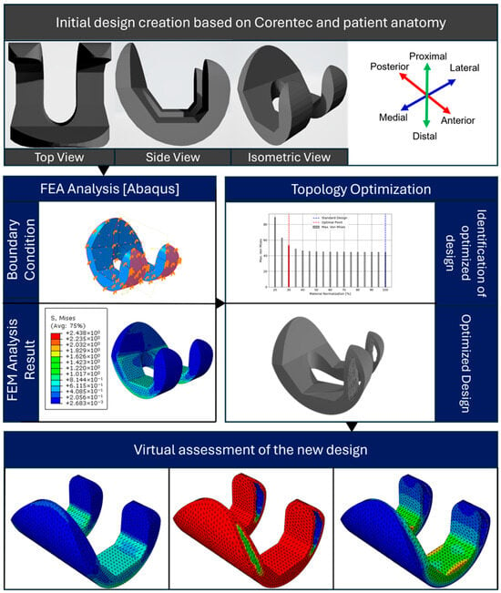
Figure 1.
The proposed framework for the methodology.
Figure 2 illustrates the preliminary CAD model of the knee prosthesis, developed using SolidWorks software. The model depicts the two primary constituent components of the prosthetic device of the initial knee prosthesis model created in SolidWorks.
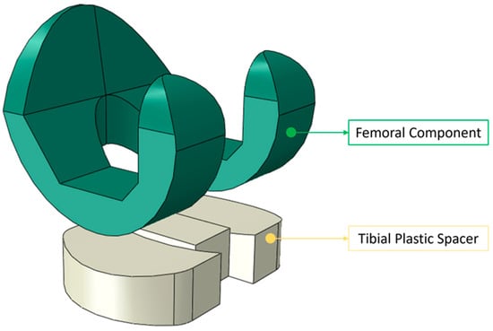
Figure 2.
The initial knee prosthesis model created in SolidWorks with its two main components, i.e., the femoral component and tibial spacer.
The initial femoral component model used for topology optimization was based on the CORENTEC total knee prosthesis geometry. Due to copyright and proprietary restrictions, the exact dimensional specifications of the model cannot be disclosed. Nevertheless, the general proportions and anatomical characteristics were consistent with a medium-sized total knee endoprosthesis, with an approximate mediolateral width of 70 mm, anteroposterior length of 60–65 mm, and component height of 70–75 mm. The posterior condylar curvature and trochlear groove geometry followed standard anatomical ratios to ensure a realistic kinematic representation. These reference proportions were sufficient for defining the design and non-design regions used in the topology optimization process.
The design task is formulated employing material interpolation techniques, such as SIMP or rational approximation of material properties (RAMP), with a penalty factor of 3 to promote discrete material distributions. The optimization problem is defined by specifying design responses (e.g., strain energy density, volumetric constraints) and formulating an objective function. The algorithm iteratively modifies the material distribution within the design domain to extremize the specified criteria, subject to imposed constraints. Upon achieving convergence, the optimization algorithm generates a new implant geometry. This optimized design undergoes virtual validation to ensure compliance with the performance metrics and manufacturing constraints. In cases of non-convergence or unsatisfactory results, the optimization parameters and constraints are recalibrated, and the process is iterated. The final phase comprises a comparative analysis between the optimized design and the initial model. This evaluation quantifies improvements in mechanical performance indices and material utilization efficiency, providing a robust basis to assess the efficacy of the optimization methodology. The proposed framework ensures a comprehensive and systematic approach to knee prosthesis design. The estimated contact surfaces of the femoral component and the tibial polyethylene spacer were modeled with matching curvature radii derived from standard implant geometries to maintain physiological articulation. These contact radii were held constant during topology optimization to isolate the influence of internal topology from geometric surface variations.
2.1. Finite Element Modeling
The knee CT and/or MRI scans of the patient were taken, after which the dimensions were used to create the initial design of the knee prosthesis in the form of a 3D CAD model for the knee prosthesis, which was then utilized to examine the characteristics of the knee prosthesis that would fit the patient in accordance with the anatomical dimensions. The parameters were set appropriately for the patient’s proximal femoral bone. The TKA design parameters were thereby customized for each patient’s knee. The initial CAD model was developed using Dassault Systèmes SolidWorks, a parametric 3D modeling and analysis platform.
The femoral component of the knee prosthesis was constructed based on the extracted dimensional parameters, with particular attention paid to the articulating surfaces and overall geometry. The 3D CAD model served as the foundation for the creation of the FEA model. The assembled model of the femoral component and plastic spacer was subjected to loading using finite element analysis (FEA) software. Figure 3 shows the FEM setup process for knee prosthesis analysis. The workflow illustrates the key steps: model import, material assignment (Ti–6Al–4V), loading application (1150 N axial force), boundary condition definition, and finite element meshing, preparing the prosthesis model for the finite element simulation.

Figure 3.
FEM setup for the knee prosthesis.
Note that the baseline model is derived from the Corentec standardized prosthesis. Due to proprietary constraints, certain parameters—including the precise curvature of the articulating surface and the mediolateral proportionality—were not fully disclosed. Consequently, these values were approximated through reverse engineering techniques. This study specifically focuses on cruciate-retaining prostheses, excluding posterior-stabilized variants from the analysis. The utilization of these specific parameters is crucial to maintain consistency with the standard model, while allowing for patient-specific customization. This approach facilitates the validation of our methodology against an established prosthetic design. The applied load of 1150 N represents the resultant joint reaction force during the mid-stance phase of gait. In the finite element simulation, this total load was resolved into three directional components—axial (compressive), anterior–posterior, and medial–lateral—to accurately reproduce realistic multi-directional stresses on the femoral component. The vector summation of these components equals the overall resultant of 1150 N. A three-dimensional quadratic tetrahedral element (C3D10) with ten nodes was used to simulate the femoral component and plastic spacer. The element sizes were set to 2.3 mm and 2.7 mm for the femoral and spacer regions, respectively.
Figure 4 illustrates a demonstration of the loading case, where combined static loads of Fx = 930 N, Fy = 2667 N, and Fz = 1070 N were applied to the upper surface of the femur component in the mediolateral, femorotibial, and anteroposterior directions, respectively [,]. These weights are consistent with a 39-year-old male patient who weighs 68 kg and has an osseointegrated TKA system. The compressive force applied to the femoral component in its axial direction is Fy = 2667 N. Both other components receive a laterally applied cross-section of the femur. For example, the forces Fx and Fy result in a projected shock force on the femur amounting to a resultant force of 1417.76 N, which can be used to simulate the impact load from a vehicle accident.
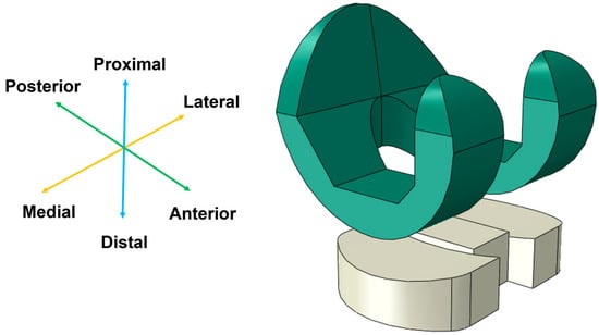
Figure 4.
Loading conditions applied to the initial TKA model.
Post-modeling in SolidWorks, the 3D representation was exported and imported into ABAQUS, an advanced finite element analysis (FEA) software suite. This transition enables sophisticated computational analysis and simulation of the prosthesis under various loading conditions and kinematic scenarios. It can be challenging to calculate the loads acting on the knee joint under real-world working situations, so for the sake of simplicity, in this scenario, we streamline the load analysis to a single-leg support scenario. The force exerted by the whole body, i.e., the body force (FB), is transferred through the hip joint and exerted onto the femur, where it is divided into two components: an axial force (FA) parallel to the femoral axis and a transverse force (FT) perpendicular to it. It can be deduced as follows by first establishing equilibrium in the femur/knee system, and assuming that the lower segment of the tibial component is fixed. Since the knee is a cylindrical joint, its response is limited to the axial load FA. In contrast, the muscles counteract the force FT and the resulting moment by producing a reactionary moment (MM), in addition to axial and transverse forces. Figure 5 shows a schematic of the human skeleton with these forces applied. In this concept, the femur and tibia are considered link elements, and the hip, knee, and ankle are considered cylindrical joints.
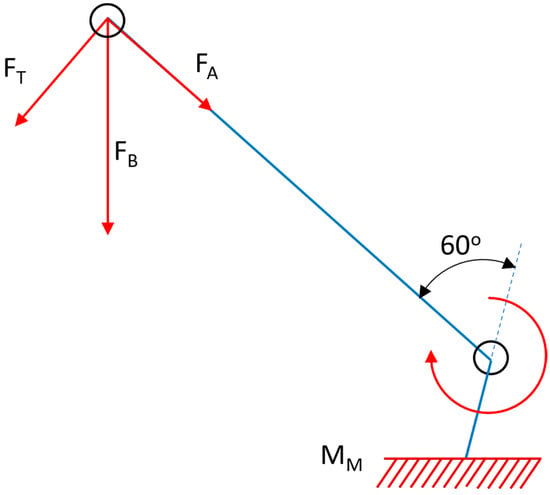
Figure 5.
Free body diagram of the forces experienced by a cylindrical knee joint under loading conditions.
In the FEM formulation, several key assumptions were incorporated into the computational model. The femoral structure was treated as a static system under quasi-static loading conditions, adhering to equilibrium principles. The applied force vectors were assumed to maintain constant magnitude and direction throughout the analysis, neglecting time-dependent variations. Moreover, the constitutive behavior of the femoral component was idealized as a linear elastic, isotropic, and homogeneous continuum, characterized by a constant Young’s modulus and Poisson’s ratio. This simplification allowed for the implementation of Hooke’s law in the stress–strain relationship, facilitating the calculation of element stiffness matrices and subsequent global assembly.
In this investigation, the analysis was simplified by neglecting transverse forces and moments induced by muscular activity, focusing exclusively on axial stresses applied to the femur. This simplification is justified, as the primary stress concentrations at the interface between the plastic insert of the prosthesis and the femoral component are predominantly generated by axial loading. The validity of the results was maintained due to the dominance of axial forces in creating contact stresses in this critical region. The femoral component of the knee model was conceptualized as a homogeneous and isotropic structure, based on a comprehensive literature review. The material properties were defined according to Table 1, which specifies Grade 5 Titanium Alloy [Ti–6Al–4V] for the femoral component. This alloy, along with cobalt–chromium alloys, represents one of the most frequently utilized materials in femoral component fabrication, due to its superior mechanical properties and biocompatibility.

Table 1.
Material properties in the FEM setup for the polyethylene femoral and tibial components of the knee prosthesis.
The tibial component was modeled using ultra-high molecular weight polyethylene (UHMW−PE), specifically for the tibial polyethylene (PE) insert. Both Ti–6Al–4V and UHMW−PE are classified as biomaterials, exhibiting excellent biocompatibility with human tissues. This classification is based on their ability to maintain functional integrity within the physiological environment, without eliciting adverse host responses. The material properties were incorporated into the finite element model using constitutive equations that describe the stress–strain relationships for each material. For the titanium alloy, a linear elastic model was employed, characterized by its Young’s modulus and Poisson’s ratio. For the sake of simplicity, UHMW−PE was also modeled by assuming it to be linearly elastic, despite its inherently viscoelastic nature. This simplification allowed for a more straightforward implementation and analysis, utilizing an equivalent Young’s modulus and Poisson’s ratio for the UHMW−PE []. When an individual maintains both feet on the ground, the vertical force (FB) generated by body weight is evenly distributed between the two legs. However, when a person stands on one foot, such as when climbing stairs, the entire body weight is supported by that single leg, significantly increasing the strain on the knee joint. This is one of the most difficult load circumstances for the knee, and is a very regular scenario. The femoral and tibial polyethylene (PE) components were subject to external boundary conditions. The PE component was fixed in all directions, whereas the femoral component was only able to translate along and rotate around its axis.
The FE code models the bonding between the femoral and tibial components as a complete constraint between the bodies, preventing any reciprocal motions or rotations. Based on the considerations in Ref. [], friction contact is anticipated between the femoral component and the PE tibial insert, with a friction coefficient of 0.01. When a person is standing with both feet firmly planted on the ground, their body weight’s vertical force (F+) is appropriately directed through their center of gravity (COG). Figure 6 shows that the force is distributed equally between the two legs in this position and travels via the knee joint. The anteroposterior, lateromedial, femoral, and tibial mechanical axes were parallel in the orientation of the femoral component and plastic spacer, which were in contact. For optimal results, the femoral component and plastic spacer were aligned at 100% of the deep knee bend cycle, as contact stress is maximized at this stage []. Continuous bonding was used to represent the contact surface between the plastic spacer and the femoral component. Between two implants, a tangential contact condition was used, and a 0.07 coefficient of friction was assumed [,].
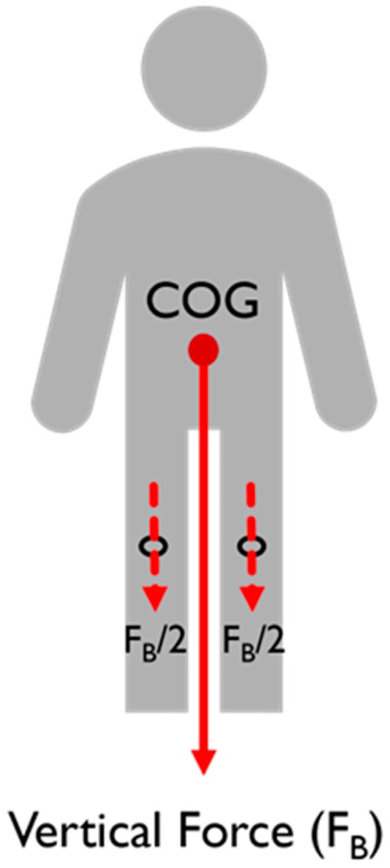
Figure 6.
Force distribution through a stationary body.
A three-dimensional quadratic tetrahedron (C3D10) with ten nodes was used to simulate the femoral component and plastic spacer. The number of meshes was set to resemble the reference for the purpose of validating the model []. The mesh sizes were selected to be (2.3 and 2.7) for the femoral components and plastic gaps, respectively. To optimize the design, the maximum von Mises stress and contact pressure that need to be investigated at the interface between the femoral component and the tibial part were selected based on our specifications, together with other relevant field output variables. It is reasonable to pay attention to the stresses and identify the contours where the stresses are concentrated. Following the completion of the FEM setup, a finite element analysis job was established for stress analysis of the initial design.
2.2. Topology Optimization
The topology optimization in ABAQUS using the Tosca Structure Optimization package was used to perform the design optimization process. The objective of the function was to minimize the strain energy response value. Here, the objective function used is expressed as follows:
The objective function, F, is aimed at minimizing the strain energy and thereby the compliance within the femoral component of the knee prosthesis. This strain energy is crucial, as it indicates the potential for material deformation and failure under load. By minimizing strain energy, the optimization process aims to enhance the prosthesis by reducing deformation, thereby increasing stiffness with the same or less material. This improvement in stiffness translates to better structural integrity and performance, ensuring the prosthesis can withstand greater loads and endure longer usage without failure. The goal function’s integral term integrates the strain energy density over the whole design domain, from the starting configuration (Ωo) to the optimum configuration (Ωn), where ε is the stress field associated with the ρ(x) material distribution.
Here, the design variables ε = ε(ρ) and ρ(x) represent the distribution of material properties within the design space.
where the function describes how the stress field varies with changes in material distribution while denotes the material density distribution function over the design domain, where defines the relative material state at each spatial coordinate , with 1 representing solid material and 0 representing void. The design space in the equation, represented by , encompasses the entire femoral component of the knee prosthesis model. This includes the intricate geometry and the features of the component that influence its mechanical behavior. Within this design space, certain regions are designated as non-design regions, meaning they are excluded from the optimization process and remain unchanged throughout. After that comes the volume of the femoral component, which is set up for the topology to be optimized.
The volume constraint (VC), , ensures that the optimized solution maintains a specified volume or mass within the specified volume of the femoral component. This constraint prevents excessive material removal during optimization, which could compromise the structural integrity of the prosthesis. Additional constraints, , address specific design requirements or performance criteria, such as maximum stress levels, or material properties. These constraints ensure that the optimized solution satisfies volumetric requirements and any other relevant constraints, such as maximum stress values. Next comes the evaluation of , as shown in Equation (2), which involves solving the governing equations of continuum mechanics, typically using the FEM. Within the Abaqus environment, the FEM simulates the mechanical response of the knee prosthesis under various loading conditions, yielding the stress distribution throughout the component. This stress distribution is then used to compute the strain energy density, contributing to the overall objective function evaluation. Iterative optimization algorithms adjust the material distribution based on the computed stress field, seeking to minimize strain energy while satisfying all constraints.
The flowchart shown in Figure 7 outlines the topology optimization process, which begins with creating the optimization task and setting a reasonable penalty factor, such as 3, for this case. Next, an interpolation technique like SIMP or RAMP is selected. The design response (e.g., strain energy, volume) is then defined. The objective function is formulated, typically minimizing the strain energy, subject to volumetric constraints. The optimization job is submitted, and it iterates until convergence. If convergence is achieved, a new optimized design is produced. If not, constraints are updated, and the process repeats. This systematic approach ensures efficient material distribution while meeting specified design criteria and constraints.
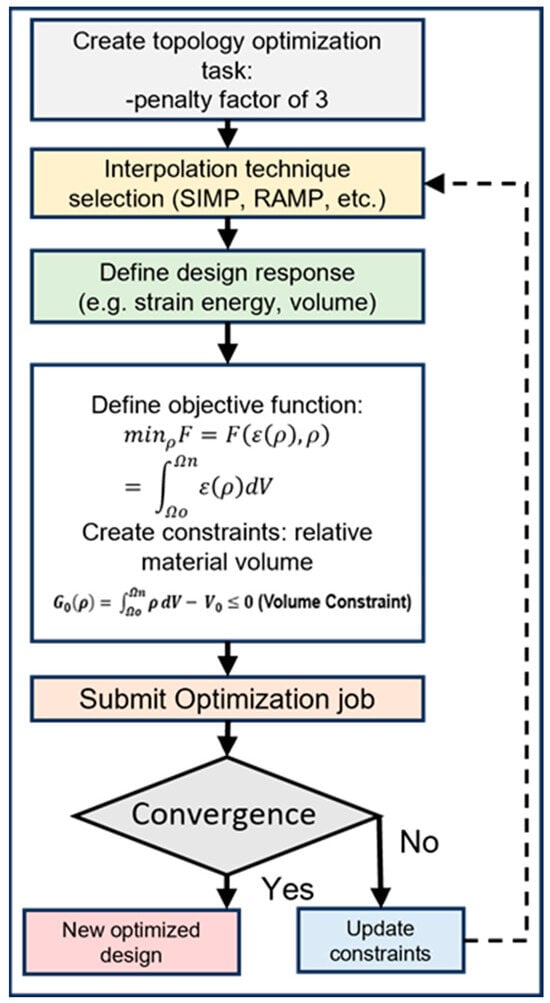
Figure 7.
Flowchart for the topology optimization process.
Material interpolation techniques of SIMP and RAMP were used for the topology optimization process. The SIMP, a commonly employed material interpolation method in topology optimization [], establishes a relationship between material properties, such as the Young’s modulus, and a continuous design variable representing material density. The method employs a power-law relationship to interpolate these properties. Its key feature is its ability to penalize intermediate density values, which drives the optimization algorithm toward more discrete, binary solutions of solid material or void. This penalization helps produce designs that are more readily manufacturable. The approach is popular due to its simplicity and effectiveness in a wide range of topology optimization problems.
Material interpolation for SIMP was performed according to the following equation:
where represents the interpolated Young’s modulus for the optimized femoral component of a knee prosthesis, utilizing the SIMP method. Here, E0 denotes the initial Young’s modulus of the material. The variable is in the range of (0 to 1) (void to solid) and acts as the design variable. The exponent is a penalization factor that enhances the contrast between void and solid regions, while represents the local stress state, and is a frequency parameter related to the stress-dependent material response. The symbol serves as a scaling factor for stress-dependent modulation, and is a parameter that controls the exponential decay of properties in low-density regions. RAMP is an alternative material interpolation scheme that was first developed to address certain limitations of the SIMP method, particularly in sensitivity analysis []. Instead of a power-law relationship, RAMP uses a rational function to interpolate material properties based on the density variable. This approach offers improved numerical stability and can provide better convergence in some cases, especially for multi-physics problems. RAMP allows for more flexible control over the penalization of intermediate densities, compared to SIMP. It can be particularly useful in scenarios where SIMP might struggle, such as problems involving material-dependent loads or certain types of constraints. The method maintains the goal of promoting binary solid–void solutions, while offering some computational advantages.
The equation provided was utilized to perform RAMP material interpolation.
In this equation, denotes the interpolated Young’s modulus for the optimized femoral component of a knee prosthesis, dependent on several variables. Here, represents the initial Young’s modulus of the material. The variable ϕ is in the range of (0 to 1) (indicating void to solid), and acts as the design variable. The parameter k serves as the RAMP penalization factor, affecting the transition between void and solid regions, while τ signifies the local stress state, and ν is a frequency parameter related to the stress-dependent material behavior. The symbol is a scaling factor for stress-dependent modulation, and δ is a parameter that governs the exponential decay of properties in regions of low density. The optimization variables for minimum density, maximum density, and maximum change each design cycle were set at (0.001, 1, and 0.25), respectively. The criteria for convergence included an element density of 0.005 and an objective function delta threshold of 0.001. For the material interpolation technique, a penalty factor of 3 was used. Throughout this process, the study maintained a holistic approach, considering both the intricate details of the prosthesis model and the realistic loading conditions to achieve an optimized TKA design.
3. Results and Discussion
The CAD and FEA models were validated by comparing the maximum contact stress value with the reference. At 100% of the deep knee bend cycle and under loading conditions of 1150 N with neutral alignment, Kim et al. reported a contact stress of 14.1 MPa at the plastic spacer or tibial component []. The contact stress in the TKA model was found to be 12.8 MPa. Figure 8 displays the FEA result of the TKA model. There could be a small discrepancy because of variations in the model’s dimensions and shape. Nevertheless, this finding suggests that the model employed in this investigation and the current model correspond well.
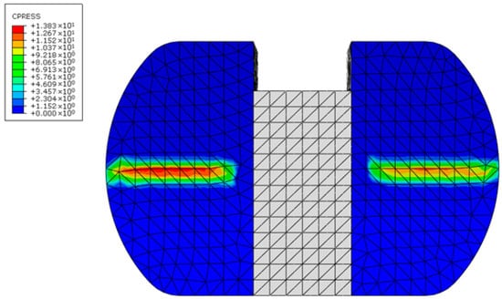
Figure 8.
Contact pressure in the tibial component of the knee prosthesis, i.e., the plastic spacer.
For the patient-specific foundation model based on the initial design, the maximum von Mises stress was 34.8 MPa, while the contact pressure on the femoral component’s contact surface was 19.9 MPa. On the tibial polyethylene, the stress was 8.7 MPa and the pressure was 17 MPa, as illustrated in Figure 9. This stress was found to be most concentrated at the interaction region of the knee prosthesis. It was found that the maximum stress value of the femoral component of 34.8 MPa was less than its yield strength, or the 795 MPa yield point for Ti–6Al–4V, which shows that the component is well within the safety margin. Contour plot distribution observations on the femoral component further emphasize the potential benefits of the proposed optimization strategy.
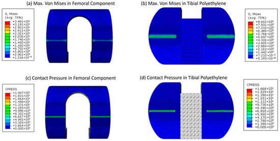
Figure 9.
Contour plots for the maximum von Mises stress and contact pressure of the femoral and tibial components (a–d), respectively.
Finally, we conducted a series of topology optimization trials, commencing with an initial preservation of 80% of the original volume. Through iterative refinement, we ascertained that retaining 40% of the topology-optimized region achieved an optimal balance between material reduction and structural integrity. This methodology effectively reduced the structure’s volume by 20%, while keeping the maximum von Mises stress and contact stress within permissible limits. The 40% retention threshold was identified as the most efficient, minimizing material usage, while ensuring the stress increase remained within a tolerable range. Figure 10 depicts this optimal configuration.
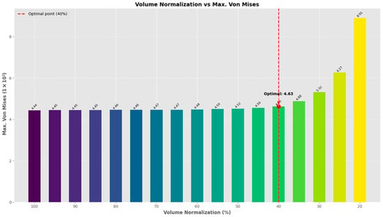
Figure 10.
Maximum von Mises stress vs. volume normalization for the topology of the limited area to be optimized.
Next, the impact of increased weight, simulating heavier individuals, on the mechanical behavior of knee prostheses during standing was also investigated, along with its respective topology-optimized designs, illustrated in Figure 11. Understanding how varying loads affect stress and contact pressure on the femoral component is crucial to optimizing prosthetic design and ensuring longevity and performance, particularly for patients who gain or lose weight after a TKA operation, and so was incorporated into the study. The data present an analysis of weight variation following total knee replacement surgery, focusing on its impact on the stress levels and contact pressures of the femoral and tibial components. As the weight increases from (400 to 800) N, the results reveal a notable escalation in both the maximum von Mises stress and contact pressure across both components. The femoral component shows a substantial rise in the maximum von Mises stress from (34.8 to 46.9) MPa, signifying a 34.7% increase. Similarly, the tibial component experiences a significant increase in maximum von Mises stress, rising from 11.4 to 15.4 MPa, marking a 35.1% elevation.
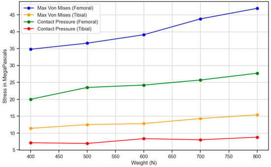
Figure 11.
Stress and contact pressure variation in the femoral and tibial components with respect to the weight of the individual.
Correspondingly, the contact pressure on the femoral component surges from 20.0 to 27.7 MPa, indicating a substantial 38.5% increase. Likewise, the contact pressure on the tibial component escalates from 7.13 to 8.78 MPa, demonstrating a 23.1% rise. These findings underscore the critical relationship between weight gain and heightened stress levels on knee replacement components. Managing post-surgical weight becomes imperative, as increased weight exerts greater pressure on the replaced knee, potentially impacting its durability and functionality over time. Consequently, the data underscore the importance of weight management as part of the post-operative care regimen for individuals undergoing knee replacement surgery. This suggests that maintaining a healthy weight is beneficial for overall well-being while also being crucial for optimizing the longevity and performance of knee replacements. By closely monitoring and managing weight, patients can mitigate the risk of excessive stress and pressure on the replaced knee joint, thus enhancing the success and longevity of the surgical intervention. It is observed that as the person moves towards obesity, the strain on the knee prosthesis increases, which is indicated by an increase in maximum von Mises forces from 77 up to 90 MPa at a body force of 2500 to 4700 N. This indicates an increase in the max. von Mises stress of 16.88%. Hence, an increasing trend is observed.
However, there are certain restrictions on the procedure. For example, since this study was based on an individual, its results are limited to that particular model and may not be generalizable. Furthermore, the model omitted anatomical characteristics, including ligaments, muscles, and the fibula bone, due to the nature of the TKA surgical process. Furthermore, all TKA components were treated as static and in an equilibrium state, with the applied load assumed to be constant. Additionally, the material properties of the TKA and bone were considered homogeneous, isotropic, and linearly elastic. Additionally, during surgery with the current total knee arthroplasty technology, it is hard to cut the bone in the exact appropriate manner. This minimalistic model has been used by a number of researchers as well [,,]. The observed increase in maximum von Mises stress and contact pressure with simulated weight escalation underscores the challenges faced by knee prostheses when subjected to higher loads. Heavier individuals impose greater mechanical stresses on the prosthetic components, which may accelerate wear and compromise implant integrity over time. These findings emphasize the importance of considering patient weight post-operatively and its implications on prosthetic design and material selection to ensure adequate strength and durability.
Figure 12 illustrates these generated designs. The sides are cut out for illustration purposes, where in reality, the outer edges would be covered. Upon completion of the optimization process, the optimized femoral component design exhibited a remarkable weight reduction of up to 20% without compromising the maximum von Mises stress, whose change remained minimal, compared to the initial design.
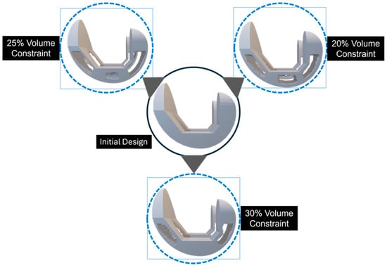
Figure 12.
The design convergence for the topology-optimized solution is demonstrated through a cutout representation, where the outer edges, although covered, are shown as cut-outs for illustrative purposes.
The observed increase in maximum von Mises stress and contact pressure with simulated weight escalation underscores the challenges faced by knee prostheses when subjected to higher loads. Figure 13 presents a comprehensive visualization of the topology optimization process for a knee prosthesis component.
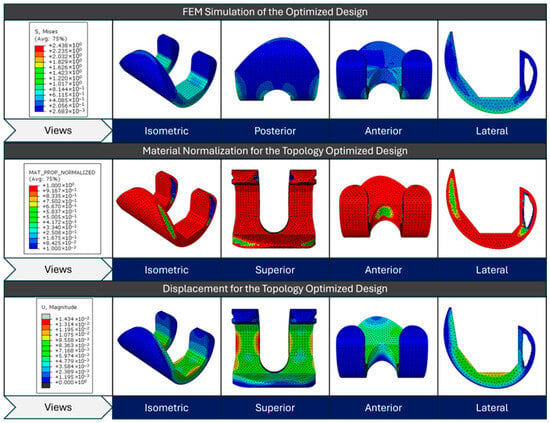
Figure 13.
FEM simulation stress results for the initial design, material normalization contour for the topology-optimized design, and displacement contour for the topology-optimized design from top to bottom, respectively.
The top row displays the initial design’s FEM simulation results, showing the von Mises stress distribution across various views (isometric, posterior, anterior, and lateral). The material normalization contour of the topology-optimized design is depicted in the center row; red areas denote high material density regions, while blue areas denote low density or material removal regions. This optimization aims to redistribute material efficiently, while maintaining structural integrity. The bottom row depicts the displacement magnitude for the optimized design under loading conditions, with colors ranging from blue (minimal displacement) to red (maximum displacement). These three sets of images collectively demonstrate how topology optimization transforms the initial design by strategically removing material to create a more efficient structure that balances stress distribution and minimizes displacement, while reducing weight.
For visualization purposes, individual color scales were applied to the stress contour plots of the reference and optimized models. Because the optimized structure exhibited considerably lower overall stress magnitudes, using a single unified legend would have compressed the color contrast and masked localized variations. Separate legends were therefore used to enhance clarity and preserve the interpretability of stress distribution patterns.
Figure 14 illustrates the topology optimization process for a knee prosthesis component using the RAMP material interpolation technique with a 70% volume constraint. The top row shows the evolution of the design across the optimization design process, where red areas indicate high material density, and blue areas represent material removal. This progression demonstrates how the algorithm refines the component’s shape, strategically removing material while maintaining structural integrity. The solid gray model presents the final optimized design. The bottom row displays the FEM simulation results for the optimized design, with a color-coded von Mises stress distribution. The stress map ranges from blue to red (low to high stress), revealing how loads are distributed across the optimized structure. Two isometric views of the final design are provided, offering a comprehensive look at the form and stress patterns of the optimized component.
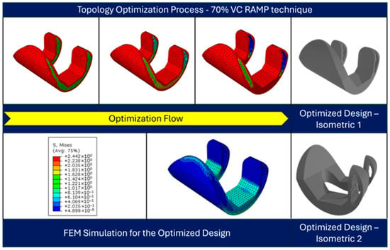
Figure 14.
Topology-optimized design at different design cycles (top), and the FEM simulation results for the optimized design (bottom).
4. Conclusions
Standardized knee prostheses play a major role in TKA, a frequent treatment designed to relieve pain and restore function in patients with severe knee arthritis or damage. The absence of individualized solutions is a major problem in knee joint prostheses, and this study presents a novel alternative. The project develops a design concept for a three-dimensional model of a knee prosthesis that is lightweight in comparison to the conventional designs and personalized for each patient by utilizing topology optimization. This method uses topology structural optimization to provide patient-specific knee prosthesis designs, in contrast to existing standardized approaches that frequently ignore unique anatomical variances. Further, the analysis demonstrates the escalating mechanical demands on knee prostheses with increasing weight; simulating heavier individuals highlights the necessity for prosthetic designs that are capable of withstanding higher loads and emphasizes the importance of selecting materials that are resilient to prolonged mechanical stress. By addressing these factors, prosthetic longevity and performance can be optimized, ultimately enhancing patient outcomes for individuals across a spectrum of body weights.
The proposed method offers a patient-specific and lightweight design for usage in future Knee Prostheses, aiming to address the limitations of traditional prosthetic solutions. To assess the efficacy of the design, the FEM was used to evaluate the mechanical performance of the component under loading and its compatibility with the specific anatomy of the individual. Since the suggested methodology offers customized solutions that have the potential to significantly improve patient well-being, it presents great promise in the field of knee joint prosthetics. An optimized design was found at 70% volume constraint using the RAMP material interpolation technique with a penalty factor of 3. In summary, the methodology employed in this study showcased the efficacy of topology design optimization in significantly enhancing knee prosthesis design. The reduction in material usage and stress, coupled with the elimination of the need for the removal of extra bone mass, underscores the potential impact of this approach on advancing prosthetic technologies. This comprehensive methodology seamlessly integrates foundational principles with innovative techniques, providing a robust framework for the optimization of knee prosthesis design.
The complex geometry obtained through topology optimization presents manufacturing challenges that cannot be addressed using conventional subtractive fabrication methods. Additive manufacturing techniques such as selective laser melting or electron beam melting would be required to realize the optimized design. However, the mechanical properties of AM-fabricated components can differ from those of bulk materials due to internal porosity, surface roughness, and microstructural anisotropy. In the present study, standard isotropic material properties were used to isolate the structural effects of topology optimization. Future work will integrate additive manufacturing process constraints and material characterization data into the optimization framework to ensure manufacturability and a realistic mechanical representation of the designed implant.
In the future, the optimized femoral component will be fabricated through 3D printing to experimentally validate its structural and functional performance under realistic load conditions. Further collaborative studies are planned to evaluate the manufacturability and potential clinical applicability of the proposed design concept through pre-clinical or surgical-level validation.
Similarly, the initial femoral component model was developed based on the standard anatomical geometry of the Corentec total knee prosthesis. This design reflects average morphometric dimensions obtained from clinical datasets and provides anatomically realistic geometry for simulation. Although direct CT-based reconstruction of individual patient femurs was not performed in this study, the Corentec-based model ensured clinically representative proportions suitable for evaluating the proposed topology optimization framework. Future research will incorporate direct CT-derived anatomical data to achieve fully patient-specific prosthesis design and validation.
Author Contributions
M.T. conceptualized the study, developed the topology optimization framework, performed data analysis, and drafted the manuscript. S.K. contributed to the optimization methodology and assisted in data analysis. J.Y.K. created the 3D models using SolidWorks and provided technical support for design validation. J.S. reviewed the methodology and contributed to manuscript editing. H.S.K. supervised the research, provided critical feedback, and reviewed the final manuscript. All authors have read and agreed to the published version of the manuscript.
Funding
This work was supported by the National Research Foundation of Korea (NRF) grant funded by the Korea government (MSIT) (RS-2025-00523019) and also supported by the “Regional Innovation System & Education (RISE)” through the Seoul RISE Center, funded by the Ministry of Education (MOE) and the Seoul Metropolitan Government (2025-RISE-01-007-04).
Institutional Review Board Statement
Not applicable.
Informed Consent Statement
Not applicable.
Data Availability Statement
The raw data supporting the conclusions of this article will be made available by the authors on request.
Conflicts of Interest
The authors declare no conflicts of interest.
Abbreviations
| TKA | Total Knee Arthroplasty |
| FEM | Finite Element Method |
| CAD | Computer-Aided Design |
| UKA | Unicompartmental Knee Arthroplasty |
| PSIs | Patient-Specific Implants |
| CT | Computed Tomography |
| MRI | Magnetic Resonance Imaging |
| AP | Anteroposterior |
| SIMP | Solid Isotropic Material with Penalization |
| RAMP | Rational Approximation of Material Properties |
| FEA | Finite Element Analysis |
| UHMW-PE | Ultra-High Molecular Weight Polyethylene |
| COG | Center of Gravity |
References
- Pande, S.; Dhatrak, P. Recent Developments and Advancements in Knee Implants Materials, Manufacturing: A Review. Mater. Today Proc. 2021, 46, 756–762. [Google Scholar] [CrossRef]
- Walker, P.S. The Artificial Knee: An Ongoing Evolution; Springer: Berlin, Germany, 2020; ISBN 3-030-38171-4. [Google Scholar]
- Bahraminasab, M.; Farahmand, F. State of the Art Review on Design and Manufacture of Hybrid Biomedical Materials: Hip and Knee Prostheses. Proc. Inst. Mech. Eng. Part H J. Eng. Med. 2017, 231, 785–813. [Google Scholar] [CrossRef]
- LeMoyne, R. Advances for Prosthetic Technology; Springer: Tokyo, Japan, 2016. [Google Scholar]
- Lee, K.; Goodman, S.B. Current State and Future of Joint Replacements in the Hip and Knee. Expert Rev. Med. Devices 2008, 5, 383–393. [Google Scholar] [CrossRef]
- Hussain, O.; Ahmad, B.; Saleem, S.S. Biomaterials for Artificial Knee Joint Replacement: A Review. Int. J. Mater. Eng. Innov. 2023, 14, 95–122. [Google Scholar] [CrossRef]
- Salama, A.; Hamer, A.J. Degenerative and Rheumatoid Arthritis (Including Joint Replacement). Surgery 2007, 25, 160–165. [Google Scholar] [CrossRef]
- Cho, W.; Kim, M.Y.; Youm, Y.S. Knee Joint Arthroplasty; Springer: Berlin, Germany, 2014; ISBN 3-642-39388-8. [Google Scholar]
- Wang, S.; Lu, L.; Currier, B.L.; Yaszemski, M.J. Orthopedic Prosthesis and Joint Implants. In An Introduction to Biomaterials; CRC PRESS: Boca Raton, FL, USA, 2006; pp. 369–393. [Google Scholar]
- Primorac, D.; Molnar, V.; Rod, E.; Jeleč, Ž.; Čukelj, F.; Matišić, V.; Vrdoljak, T.; Hudetz, D.; Hajsok, H.; Borić, I. Knee Osteoarthritis: A Review of Pathogenesis and State-of-the-Art Non-Operative Therapeutic Considerations. Genes 2020, 11, 854. [Google Scholar] [CrossRef]
- Fleming, B.C.; Hulstyn, M.J.; Oksendahl, H.L.; Fadale, P.D. Ligament Injury, Reconstruction and Osteoarthritis. Curr. Opin. Orthop. 2005, 16, 354. [Google Scholar] [CrossRef]
- Logerstedt, D.S.; Ebert, J.R.; MacLeod, T.D.; Heiderscheit, B.C.; Gabbett, T.J.; Eckenrode, B.J. Effects of and Response to Mechanical Loading on the Knee. Sports Med. 2022, 52, 201–235. [Google Scholar] [CrossRef]
- Schiavone Panni, A.; Cerciello, S.; Vasso, M.; Tartarone, M. Stiffness in Total Knee Arthroplasty. J. Orthop. Traumatol. 2009, 10, 111–118. [Google Scholar] [CrossRef]
- Sultan, P.G.; Most, E.; Schule, S.; Li, G.; Rubash, H.E. Optimizing Flexion after Total Knee Arthroplasty: Advances in Prosthetic Design. Clin. Orthop. Relat. Res. 2003, 416, 167–173. [Google Scholar] [CrossRef]
- Wu, F.; Chen, J.; Wang, W. A Dynamic Multi-Objective Evolutionary Algorithm Based on Prediction. J. Comput. Des. Eng. 2023, 10, 1–15. [Google Scholar] [CrossRef]
- Anderson, A.S.; Loeser, R.F. Why Is Osteoarthritis an Age-Related Disease? Best Pract. Res. Clin. Rheumatol. 2010, 24, 15–26. [Google Scholar] [CrossRef]
- Zhang, Y.; Jordan, J.M. Epidemiology of Osteoarthritis. Clin. Geriatr. Med. 2010, 26, 355–369. [Google Scholar] [CrossRef] [PubMed]
- Carr, A.J.; Robertsson, O.; Graves, S.; Price, A.J.; Arden, N.K.; Judge, A.; Beard, D.J. Knee Replacement. Lancet 2012, 379, 1331–1340. [Google Scholar] [CrossRef] [PubMed]
- Grimmer, M.; Seyfarth, A. Mimicking Human-like Leg Function in Prosthetic Limbs. In Neuro-Robotics: From Brain Machine Interfaces to Rehabilitation Robotics; Springer: Dordrecht, The Netherlands, 2014; pp. 105–155. [Google Scholar]
- Gunston, F.H. Polycentric Knee Arthroplasty: Prosthetic Simulation of Normal Knee Movement. J. Bone Jt. Surg. Br. Vol. 1971, 53, 272–277. [Google Scholar] [CrossRef]
- Causero, A.; Di Benedetto, P.; Beltrame, A.; Gisonni, R.; Cainero, V.; Pagano, M. Design Evolution in Total Knee Replacement: Which Is the Future. Acta Biomed. 2014, 85, 5–19. [Google Scholar]
- Pal, S.; Pal, S. The Knee Joint and Its Artificial Replacement. In Design of Artificial Human Joints & Organs; Springer: Boston, MA, USA, 2014; pp. 195–210. [Google Scholar]
- Zach, L.; Kunčická, L.; Růžička, P.; Kocich, R. Design, Analysis and Verification of a Knee Joint Oncological Prosthesis Finite Element Model. Comput. Biol. Med. 2014, 54, 53–60. [Google Scholar] [CrossRef]
- Canovas, F.; Dagneaux, L. Quality of Life after Total Knee Arthroplasty. Orthop. Traumatol. Surg. Res. 2018, 104, S41–S46. [Google Scholar] [CrossRef]
- Von Keudell, A.; Sodha, S.; Collins, J.; Minas, T.; Fitz, W.; Gomoll, A. Patient Satisfaction after Primary Total and Unicompartmental Knee Arthroplasty: An Age-Dependent Analysis. Knee 2014, 21, 180–184. [Google Scholar] [CrossRef]
- Sohail, M.; Park, J.; Lee, J.; Kim, H.S. Limitations in Transitioning from Conventional to Modern Total Knee Arthroplasty: A Review. Multiscale Sci. Eng. 2023, 5, 77–85. [Google Scholar] [CrossRef]
- Batailler, C.; Swan, J.; Sappey Marinier, E.; Servien, E.; Lustig, S. New Technologies in Knee Arthroplasty: Current Concepts. J. Clin. Med. 2020, 10, 47. [Google Scholar] [CrossRef] [PubMed]
- Shu, L.; Yao, J.; Yamamoto, K.; Sato, T.; Sugita, N. In Vivo Kinematical Validated Knee Model for Preclinical Testing of Total Knee Replacement. Comput. Biol. Med. 2021, 132, 104311. [Google Scholar] [CrossRef] [PubMed]
- Kulkarni, P.G.; Paudel, N.; Magar, S.; Santilli, M.F.; Kashyap, S.; Baranwal, A.K.; Zamboni, P.; Vasavada, P.; Katiyar, A.; Singh, A.V. Overcoming Challenges and Innovations in Orthopedic Prosthesis Design: An Interdisciplinary Perspective. Biomed. Mater. Devices 2023, 2, 58–69. [Google Scholar] [CrossRef] [PubMed]
- Sohail, M.; Kim, J.Y.; Park, J.; Kim, H.S.; Lee, J. Femoral Coordinate System Based on Articular Surfaces: Implications for Computer-Assisted Knee Arthroplasty. Comput. Biol. Med. 2023, 163, 107229. [Google Scholar] [CrossRef]
- Moayedfar, M.; Abdul-Rani, A.M.; Kumar, D. An Integrated Approach Utilising Imaging and Computer Aided Design of MR Images for Customized Medical Knee Implants Production. J. Med. Imaging Health Inform. 2015, 5, 1839–1842. [Google Scholar] [CrossRef]
- Wong, K.C. 3D-Printed Patient-Specific Applications in Orthopedics. Orthop. Res. Rev. 2016, 8, 57–66. [Google Scholar] [CrossRef]
- Nguyen, V.D.; LaCour, M.T.; Dessinger, G.M.; Komistek, R.D. Advancements in Total Knee Arthroplasty Kinematics: 3D Implant Computer Aided Design Model Creation through X-Ray or Fluoroscopic Images. Clin. Biomech. 2023, 109, 106091. [Google Scholar] [CrossRef]
- Kang, K.; Son, J.; Suh, D.; Kwon, S.; Kwon, O.; Koh, Y. Patient-Specific Medial Unicompartmental Knee Arthroplasty Has a Greater Protective Effect on Articular Cartilage in the Lateral Compartment: A Finite Element Analysis. Bone Jt. Res. 2018, 7, 20–27. [Google Scholar] [CrossRef]
- Kurtz, W.B.; Slamin, J.E.; Doody, S.W. Bone Preservation in a Novel Patient Specific Total Knee Replacement. Reconstr. Rev. 2016, 6. [Google Scholar] [CrossRef]
- Fitz, W. Unicompartmental Knee Arthroplasty with Use of Novel Patient-Specific Resurfacing Implants and Personalized Jigs. J. Bone Jt. Surg. 2009, 91, 69–76. [Google Scholar] [CrossRef]
- Jemmett, P.; Roy, S. The iDuo Bi-Compartmental Knee Replacement: Our Early Experience. Reconstr. Rev. 2016, 6, 149. [Google Scholar] [CrossRef]
- Arnholdt, J.; Kamawal, Y.; Holzapfel, B.M.; Ripp, A.; Rudert, M.; Steinert, A.F. Evaluation of Implant Fit and Frontal Plane Alignment after Bi-Compartmental Knee Arthroplasty Using Patient-Specific Instruments and Implants. Arch. Med. Sci. 2018, 14, 1424–1431. [Google Scholar] [CrossRef]
- Pastides, P.; Nathwani, D. The Role of Newer Technologies in Knee Arthroplasty. Orthop. Trauma 2017, 31, 47–52. [Google Scholar] [CrossRef]
- Sohail, M.; Park, J.; Kim, J.Y.; Kim, H.S.; Lee, J. Modified Whiteside’s Line-Based Transepicondylar Axis for Imageless Total Knee Arthroplasty. Mathematics 2022, 10, 3670. [Google Scholar] [CrossRef]
- Noble, J.W., Jr.; Moore, C.A.; Liu, N. The Value of Patient-Matched Instrumentation in Total Knee Arthroplasty. J. Arthroplast. 2012, 27, 153–155. [Google Scholar] [CrossRef] [PubMed]
- Klatt, B.A.; Goyal, N.; Austin, M.S.; Hozack, W.J. Custom-Fit Total Knee Arthroplasty (OtisKnee) Results in Malalignment. J. Arthroplast. 2008, 23, 26–29. [Google Scholar] [CrossRef]
- Bali, K.; Walker, P.; Bruce, W. Custom-Fit Total Knee Arthroplasty: Our Initial Experience in 32 Knees. J. Arthroplast. 2012, 27, 1149–1154. [Google Scholar] [CrossRef]
- Mahoney, O.M.; Kinsey, T. Overhang of the Femoral Component in Total Knee Arthroplasty: Risk Factors and Clinical Consequences. J. Bone Jt. Surg. 2010, 92, 1115–1121. [Google Scholar] [CrossRef]
- Vaidya, S.V.; Ranawat, C.S.; Aroojis, A.; Laud, N.S. Anthropometric Measurements to Design Total Knee Prostheses for the Indian Population. J. Arthroplast. 2000, 15, 79–85. [Google Scholar] [CrossRef]
- Ranawat, C.S. The Patellofemoral Joint in Total Condylar Knee Arthroplasty: Pros and Cons Based on Five-to Ten-Year Follow-up Observations. Clin. Orthop. Relat. Res. 1986, 205, 93–99. [Google Scholar] [CrossRef]
- Ha, C.W.; Na, S.E. The Correctness of Fit of Current Total Knee Prostheses Compared with Intra-Operative Anthropometric Measurements in Korean Knees. J. Bone Jt. Surg. Br. Vol. 2012, 94, 638–641. [Google Scholar] [CrossRef]
- Nicoll, D.; Rowley, D.I. Internal Rotational Error of the Tibial Component Is a Major Cause of Pain after Total Knee Replacement. J. Bone Jt. Surg. Br. Vol. 2010, 92, 1238–1244. [Google Scholar] [CrossRef]
- Cheng, C.-K.; Wang, X.-H.; Luan, Y.-C.; Zhang, N.-Z.; Liu, B.-L.; Ma, X.-Y.; Nie, M.-D. Challenges of Pre-Clinical Testing in Orthopedic Implant Development. Med. Eng. Phys. 2019, 72, 49–54. [Google Scholar] [CrossRef] [PubMed]
- Cenni, F.; Timoncini, A.; Ensini, A.; Tamarri, S.; Belvedere, C.; D’Angeli, V.; Giannini, S.; Leardini, A. Three-dimensional Implant Position and Orientation after Total Knee Replacement Performed with Patient-specific Instrumentation Systems. J. Orthop. Res. 2014, 32, 331–337. [Google Scholar] [CrossRef] [PubMed]
- Xiang, S.; Zhao, Y.; Li, Z.; Feng, B.; Weng, X. Clinical Outcomes of Ceramic Femoral Prosthesis in Total Knee Arthroplasty: A Systematic Review. J. Orthop. Surg. Res. 2019, 14, 57. [Google Scholar] [CrossRef] [PubMed]
- Tokgoz, E.; Levitt, S.; Sosa, D.; Carola, N.A.; Patel, V. Complications of Total Knee Arthroplasty. In Total Knee Arthroplasty; Springer Nature: Cham, Switzerland, 2023; pp. 71–93. ISBN 978-3-031-31099-7. [Google Scholar]
- Wei, P.; Liu, J.; Li, X.; Su, C. Topology Optimization Introducing Manual Intervention. Res. Sq. 2023. [Google Scholar] [CrossRef]
- Azad, M.M.; Kim, D.; Khalid, S.; Kim, H.S. Topology Optimization and Fatigue Life Estimation of Sustainable Medical Waste Shredder Blade. Mathematics 2022, 10, 1863. [Google Scholar] [CrossRef]
- Shin, S.; Shin, D.; Kang, N. Topology Optimization via Machine Learning and Deep Learning: A Review. J. Comput. Des. Eng. 2023, 10, 1736–1766. [Google Scholar] [CrossRef]
- Wang, Y.; Zhang, Q.; Wang, G.-G.; Hu, Z. An Enhancing Many-Objective Evolutionary Algorithm Using Chaotic Mapping and Solution Ranking Mechanism for Large-Scale Optimization. J. Comput. Des. Eng. 2022, 9, 1974–1994. [Google Scholar] [CrossRef]
- Sigmund, O.; Maute, K. Topology Optimization Approaches: A Comparative Review. Struct. Multidisc. Optim. 2013, 48, 1031–1055. [Google Scholar] [CrossRef]
- Zhang, A.; Chen, H.; Liu, Y.; Wu, N.; Chen, B.; Zhao, X.; Han, Q.; Wang, J. Customized Reconstructive Prosthesis Design Based on Topological Optimization to Treat Severe Proximal Tibia Defect. Bio-Des. Manuf. 2021, 4, 87–99. [Google Scholar] [CrossRef]
- Wu, N.; Li, S.; Zhang, B.; Wang, C.; Chen, B.; Han, Q.; Wang, J. The Advances of Topology Optimization Techniques in Orthopedic Implants: A Review. Med. Biol. Eng. Comput. 2021, 59, 1673–1689. [Google Scholar] [CrossRef] [PubMed]
- Ramaniraka, N.A.; Rakotomanana, L.R.; Leyvraz, P.-F. The Fixation of the Cemented Femoral Component: Effects of Stem Stiffness, Cement Thickness and Roughness of the Cement-Bone Surface. J. Bone Jt. Surg. Br. Vol. 2000, 82, 297–303. [Google Scholar] [CrossRef]
- Chong, D.Y.R.; Hansen, U.N.; Amis, A.A. Analysis of Bone–Prosthesis Interface Micromotion for Cementless Tibial Prosthesis Fixation and the Influence of Loading Conditions. J. Biomech. 2010, 43, 1074–1080. [Google Scholar] [CrossRef] [PubMed]
- Carr, B.C.; Goswami, T. Knee Implants–Review of Models and Biomechanics. Mater. Des. 2009, 30, 398–413. [Google Scholar] [CrossRef]
- Ingrassia, T.; Nalbone, L.; Nigrelli, V.; Tumino, D.; Ricotta, V. Finite Element Analysis of Two Total Knee Joint Prostheses. Int. J. Interact. Des. Manuf. 2013, 7, 91–101. [Google Scholar] [CrossRef]
- Kang, K.-T.; Koh, Y.-G.; Son, J.; Kwon, O.-R.; Lee, J.-S.; Kwon, S.-K. Influence of Increased Posterior Tibial Slope in Total Knee Arthroplasty on Knee Joint Biomechanics: A Computational Simulation Study. J. Arthroplast. 2018, 33, 572–579. [Google Scholar] [CrossRef]
- Estupiñán, J.A.; Bartel, D.L.; Wright, T.M. Residual Stresses in Ultra-high Molecular Weight Polyethylene Loaded Cyclically by a Rigid Moving Indenter in Nonconforming Geometries. J. Orthop. Res. 1998, 16, 80–88. [Google Scholar] [CrossRef]
- Sathasivam, S.; Walker, P.S. A Computer Model with Surface Friction for the Prediction of Total Knee Kinematics. J. Biomech. 1997, 30, 177–184. [Google Scholar] [CrossRef]
- Kim, J.Y.; Sohail, M.; Kim, H.S. Rapid Estimation of Contact Stresses in Imageless Total Knee Arthroplasty. Mathematics 2023, 11, 3527. [Google Scholar] [CrossRef]
- Zuo, W.; Saitou, K. Multi-Material Topology Optimization Using Ordered SIMP Interpolation. Struct. Multidisc. Optim. 2017, 55, 477–491. [Google Scholar] [CrossRef]
- Gao, T.; Zhang, W. Topology Optimization Involving Thermo-Elastic Stress Loads. Struct. Multidisc. Optim. 2010, 42, 725–738. [Google Scholar] [CrossRef]
- Hua, X.; Wroblewski, B.M.; Jin, Z.; Wang, L. The Effect of Cup Inclination and Wear on the Contact Mechanics and Cement Fixation for Ultra High Molecular Weight Polyethylene Total Hip Replacements. Med. Eng. Phys. 2012, 34, 318–325. [Google Scholar] [CrossRef]
Disclaimer/Publisher’s Note: The statements, opinions and data contained in all publications are solely those of the individual author(s) and contributor(s) and not of MDPI and/or the editor(s). MDPI and/or the editor(s) disclaim responsibility for any injury to people or property resulting from any ideas, methods, instructions or products referred to in the content. |
© 2025 by the authors. Licensee MDPI, Basel, Switzerland. This article is an open access article distributed under the terms and conditions of the Creative Commons Attribution (CC BY) license (https://creativecommons.org/licenses/by/4.0/).