Abstract
In the newly developed hybrid prefabricated RC-steel structure (SS) foundation pit bracing system, the main braces are the main load-carrying components, which are assembled from standardized prefabricated reinforced concrete beam segments (referred to as beam segments). To facilitate assembly, beam segments are equipped with beam sleeves and beam-end connection holes. The holes at the end of the beam can cause stress concentration problems, while the beam sleeve has a reinforcing effect on the end of the beam segment. To investigate the influence of beam-end holes and beam sleeves on the compressive mechanical properties of beam segments, a numerical simulation study was conducted. Taking the beam segment (specification: 4500 mm × 700 mm × 800 mm) used in a certain foundation pit support project as the research object (i.e., specimen), Abacus software was first used to build parameterized models of beam segments with holes and beam sleeves using the concrete damaged plasticity model (CDP) and the steel double-line strengthening model. Then the influence of three factors, namely end face friction coefficient, beam-end holes diameter, and beam sleeve thickness, on the axial compression performance of the beam segment specimens was studied. The results indicated that the axial compressive capacity of specimens without a beam sleeve decreased with increasing hole diameter; the axial compressive bearing capacities of specimens with hole diameters of 35 mm, 40 mm, and 45 mm were 13,300 kN, 12,500 kN, and 12,300 kN, respectively, which are 11.3%, 16.7%, and 18% lower than the compressive bearing capacity of specimens without holes (15,000 kN). When both a beam sleeve and holes were present, the holes had a negligible influence on the compressive capacity, while the beam sleeve played a decisive role. The compressive bearing capacity increased with greater beam sleeve thickness; the peak bearing capacities of the specimens with beam sleeves 5 mm, 10 mm, and 15 mm thick were 16,200 kN, 16,500 kN, and 17,600 kN, respectively. As the end face friction coefficient decreased from 0.6 to 0.1, the location of maximum compressive damage shifted toward the end face of the beam segment, and the area of maximum concrete damage gradually migrated toward the hole locations. The study demonstrates that the confinement effect of the beam sleeve can compensate for the weakening effect caused by the holes and confirms that the designs of holes in beam segment ends and in the beam sleeve can meet safety requirements.
1. Introduction
An internal bracing system is widely used in large-scale foundation pit projects, which consists of two components: horizontal bracing and vertical supports. Horizontal bracing comprises crown beams (or waist beams) and horizontal bracing beams. Vertical supports are typically reinforced concrete (RC) columns or steel columns. Currently, the most prevalent internal bracing systems for large deep foundation pit projects are the cast-in-place RC bracing system and the prefabricated steel structure (SS) bracing system. The cast-in-place reinforced concrete bracing system is widely adopted in foundation engineering due to its superior load-bearing capacity, high overall rigidity, effective deformation control, and dual functionality as construction walkways. However, the system has significant defects, such as a long construction period and difficulty in dismantling [,,,]. In contrast, although the prefabricated SS bracing system has the advantages of fast construction and reusability, its high cost and large structural deformation, as well as its strict requirements on processing accuracy and on site installation, are also prominent shortcomings [,,]. By absorbing the advantages of cast-in-place RC and prefabricated SS bracing systems and discarding their disadvantages, a hybrid prefabricated RC-SS foundation pit bracing system that is easy to install and dismantle and can be recycled and reused multiple times has been developed to respond to the demand of green construction [,,].
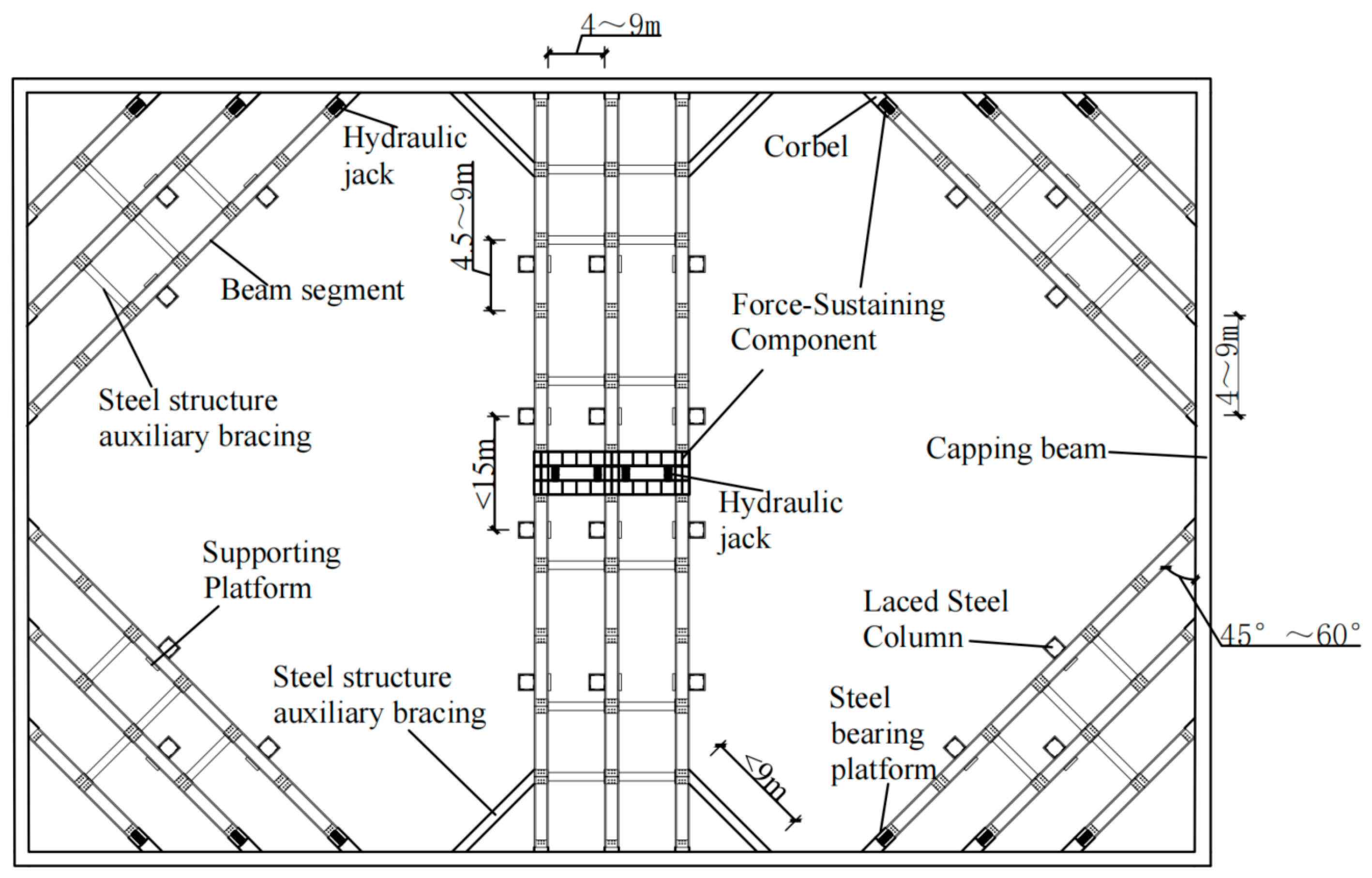
As shown in Figure 1, a typical planar layout of the hybrid prefabricated RC-SS foundation pit bracing system consists of a capping beam, waist beams, reinforced concrete beam segments (referred to as “beam segment”), auxiliary SS bracing, corbels, laced steel columns, hydraulic jacks, steel-bearing platforms, supporting platforms, and the force-sustaining components. The beam segments, which are assembled to form the main bracing of the bracing system and act as the primary load-bearing units, serve as the core components of the system. To enhance the overall integrity of the main bracing, holes are arranged at both ends of the beam segments to facilitate connections between segments (via steel plates and screws) and connections to auxiliary SS bracing. Meanwhile, to strengthen the beam segment ends and prevent edge damage during repeated reusing processes, a protective beam sleeve is installed around the concrete surface of the beam segment (the detailed structure of the beam segment is described below). Due to the structural nature of the bracing system, the main bracing beams (or the beam segments in the main bracing) mainly bear the axial pressure transmitted from the retaining structure of the foundation pit, as well as the relatively small shear and bending moments caused by their own weight, while the auxiliary SS bracing beams have very little force and mainly serve to enhance the stability of the bracing system.
Figure 1.
Layout diagram of the hybrid prefabricated RC-SS foundation pit bracing system.
Holes at both ends of the beam segment reduce its cross-sectional area, causing stress concentration around the holes and consequently affecting the segment’s compressive load-bearing capacity. Meanwhile, the beam sleeve provides a strengthening effect. The combined impact of the holes and beam sleeve on the beam segment’s compressive mechanical properties remains unknown.
In recent years, extensive research has been conducted on the effects of openings in beams (or columns) on the mechanical properties of beams (or columns) and how to strengthen damaged beams (or columns). Tahir, Muhammad Fiaz et al. studied RC columns with transverse circular openings and found that individual transverse openings with an opening rate exceeding 15% would cause a significant reduction in the bearing capacity of RC columns; they also found that by increasing the cross-sectional area of the column, increasing the reinforcement ratio, increasing the concrete strength, and thickening the wall thickness of the embedded steel pipe, the bearing capacities of the columns can be enhanced []. Campione, Giuseppe et al. found that increasing the diameter of the openings in RC columns can lead to a decrease in bearing capacity and that this phenomenon was alleviated by increasing the number of stirrups []. Liang, Jiongfeng et al. investigated the behavior of columns with web openings under axial compression and found that the opening ratio has a significant effect on load-carrying capacity, while the shape of the openings has a relatively small effect []. Minafò, Giovanni found that the maximum permissible hole diameter for avoiding splitting failure depends on the ratio of the longitudinal steel reinforcement provided in the columns. For the most commonly used longitudinal reinforcement ratio, the aperture-to-column-width ratio should be limited to a value less than 0.2 []. Yang Xu’s research found that opening holes in RC beams weaken the beam section, shift the plastic hinge area of the beam segment outward, and increase the stress of the concrete around the hole and the hoop reinforcement on the hole side; and as the size of the hole increases, the cross-section of the beam is weakened more. Both carbon fiber cloth reinforcement and steel wrapping reinforcement can make the ultimate bearing capacity and hysteresis performance of perforated nodes with beam ends close to those of unperforated nodes []. Hu, Qiang and others found that a skeleton composed of angle steel and lath can effectively restrain the concrete in the column specimen. With the increase of angle-steel size, the bearing capacity of the specimen increases by no more than 10%. However, with the decrease of flat noodle spacing, the bearing capacity can be increased by more than 15% []. Numerous studies have shown that thin-walled steel pipes significantly improve the axial compressive bearing capacity of the reinforced concrete columns [,,,]. Additionally, several new materials and structures have also been widely applied in the external reinforcement of beams. FRP is used for beam reinforcement [,,,]. Hu, T. Y. et al. established an indicator system for predicting the failure modes of fiber-reinforced polymer (FRP)-reinforced concrete (RC) beams under bending conditions []. Abuodeh et al. used neural networks after feature selection to predict the shear strength of RC beams strengthened with a FRP []. The retrofitting of RC beams using CFRP panels resulted in beams exhibiting superior load-bearing capacity and deformation capability compared to standard beams in terms of crack resistance and durability failure [,,,]. Yan et al. used a hybrid artificial neural network with a genetic algorithm to assess the anchorage reliability of GFRP bars to concrete [].
From the existing research, it can be found that there is currently a lack of research on the combined effect of beam-end openings and beam sleeves on the mechanical properties of beam segments. To address this problem, the ABAQUS 6.9 (developed by Dassault Systèmes, Paris, France) finite element numerical simulation method was used to study the load displacement curve of beam segments, the distribution of plastic strain of concrete in beam segments, and the stress concentration phenomenon and damage of beam segment holes under different parameters. Considering that the bending moment and shear force in the cross-section of the beam are relatively small and vary with the position of the section of the beam, this study ignores the weight of the beam section itself and only considers the effects of the hole diameter, the thickness of the beam sleeve, and the end restraint friction coefficient on the axial load-carrying capacity of the beam segment. The findings provide a theoretical basis and design references for the engineering application of this hybrid prefabricated RC-SS foundation pit bracing system.
2. Materials and Methods
2.1. Source and Characteristics of Research Subject
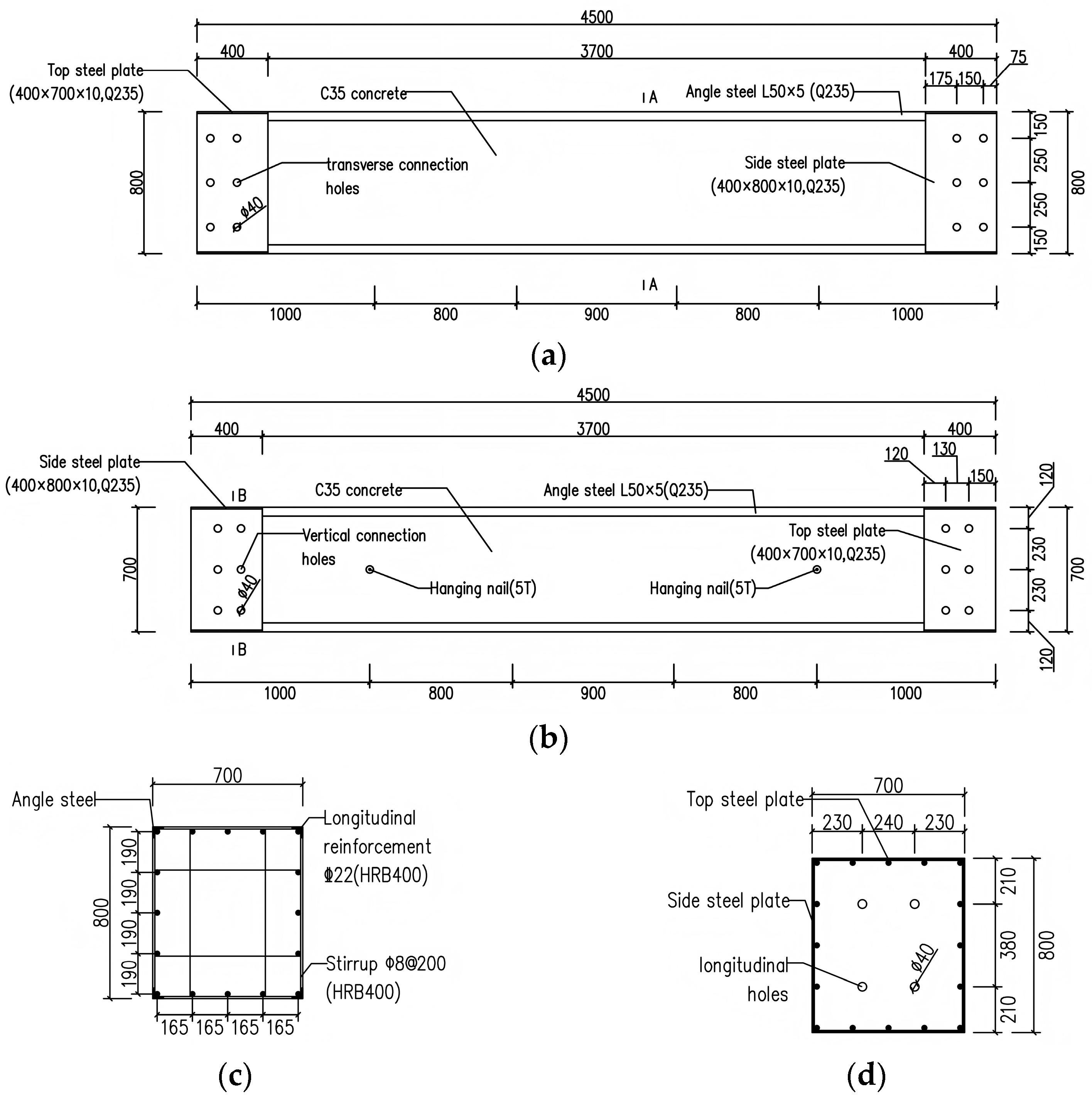
The research object of this study is the beam segment (i.e., specimen, as shown in Figure 2), which has been used as a component of the main bracing in a foundation pit project in Wuhan, China in 2024. The structure and dimensions of the beam segment are shown in Figure 3. The ends of the beam segment are pre-set with longitudinal holes for inserting connection bar, transverse connection holes, and vertical connection holes. Among them, the longitudinal holes are blind holes with a depth of 300 mm, and the transverse and vertical connection holes are through holes. In order to strengthen the beam ends and edges, a beam sleeve made of eight steel plates and four angle steels was wrapped on the beam segment.
Figure 2.
Picture of beam segment.
Figure 3.
Structural diagram of beam segment. (unit: mm). (a) side view of beam segment, (b) top view of beam segment, (c) A-A cross-section diagram, (d) B-B cross-section diagram.
In engineering applications, the beam segments need to be jionted together to form the main bracing, and then connected with the auxiliary SS bracing to form an integrated bracing system. Two typical types of connection node structures are shown in Figure 4: One type is the SS auxiliary bracing which is connected to one side or both sides of the beam segment connection joint, and the other type is only connected to the beam segment. When joining beam segments together to form a main bracing, connection bars are first inserted into the longitudinal holes to achieve preliminary alignment, then the beam segments are aligned, and finally the connecting steel plates or end plates of the SS auxiliary bracing are fastened across the connection node by passing screws through the transverse and vertical connection holes in the beam segments, thereby achieving a stable and reliable connection.
Figure 4.
Schematic diagram of beam segment connection node structures. (a) node connecting the auxiliary SS bracing, (b) node not connecting the auxiliary SS bracing.
A beam segment is divided into three key components for simulation: beam sleeve, rectangular concrete, and reinforcing skeleton. Their 3D geometric models are shown in Figure 5, Figure 6 and Figure 7 respectively.
Figure 5.
3D geometric model of the steel beam sleeve.
Figure 6.
3D geometric model of the rectangular concrete of the beam segment.
Figure 7.
3D geometric model of the reinforcement skeleton of the beam segment.
2.2. Finite Element Modeling of Beam Segments and Model Parameter Configuration
The rectangular concrete of the beam segment is simulated with solid units using isotropic assumptions (Figure 6). The main role of steel reinforcement in RC structures is to carry tensile forces. At the same time, relative slip occurs between the tension bars and stirrups and the concrete. In axial compression analysis, the sliding effect between concrete and reinforcement has a negligible impact on the compressive bearing capacity. Therefore, the reinforcement and stirrups are modeled using truss elements (Figure 7). As the thickness of the beam sleeve steel plate is less than one-tenth of the dimensions in other directions of the beam sleeve, the beam sleeve is simulated as the shell unit. Neglecting relative slip between the concrete and the beam sleeve, the Tie connection is used to simulate the connection behavior between the steel plates of the beam sleeve and the concrete.
2.2.1. Module Division
Except for the solid concrete in treatment 1 treated with first-order hexahedral mesh division, the solid concrete in the other treatments is divided with second-order tetrahedral mesh division, with a global mesh size set to 200 mm. The curvature capture is set to 30 degrees/360 degrees to densify the position of curvature changes; the steel bars in this structure are subjected to compression, and the steel bars are made of T3D2 truss elements with a size of 200 mm. The beam sleeve is made of shell elements with a global mesh size of 50 mm, and the curvature capture is set the same as that of concrete. The mesh division model for treatment 2–18 is shown in Figure 8 and Figure 9.
Figure 8.
Schematic diagram of beam concrete mesh division.
Figure 9.
Schematic diagram of mesh division for beam sleeve.
2.2.2. Concrete CDP Principal Modeling
The CDP in ABAQUS 6.9 is a plasticity-based model with a continuous damage model, whose basic assumption is that isotropic compression and tension lead to damage due to cracking of the material []. The model is commonly used in implicit solving and explicit dynamic analysis to show the inelastic cracking behavior of concrete materials of various strengths in post-processing []. The CDP parameters (five of them shown in Table 1) mainly consist of two elastic parameters, five plastic parameters, four model parameters describing the tensile behavior, and four model parameters describing the compressive behavior [,,].
Table 1.
CDP Parameters.
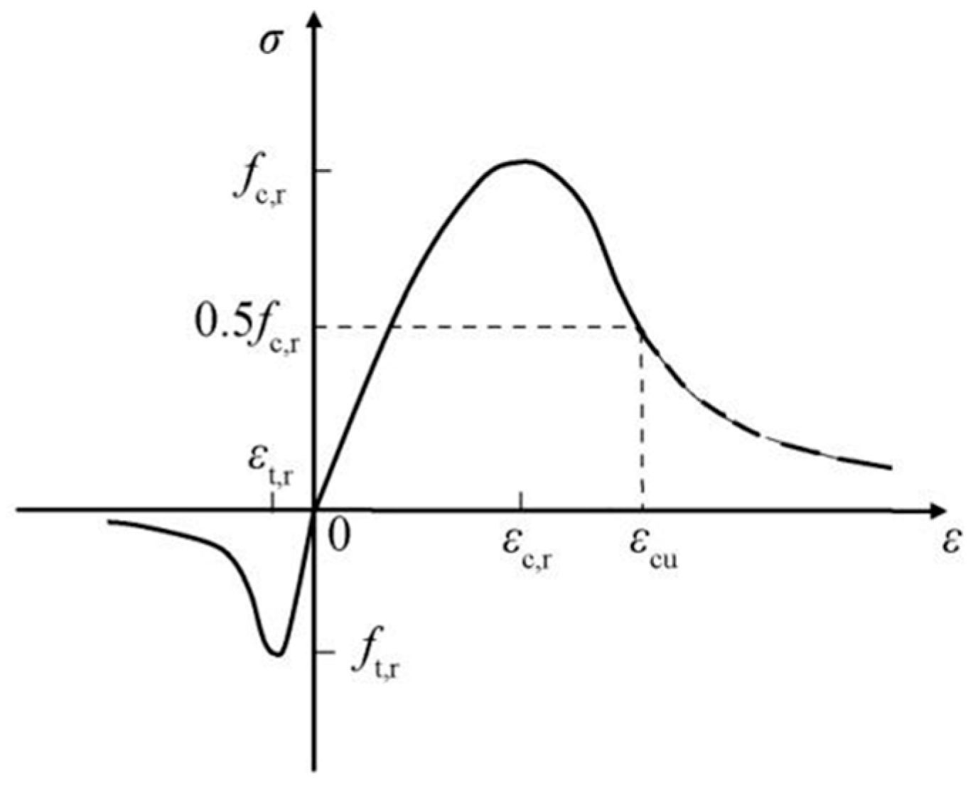
The stress–strain relationship for the CDP is chosen from the concrete principal relationship given in the Code for Design of Concrete Structures (GB 50010-2010) [], the stress–strain relationship for the elastic phase of concrete is defined by the Young’s modulus E and Poisson’s ratio λ of concrete [], and the stress–strain relationship for the inelastic phase is determined by using the stress–strain relationship for concrete provided in the code. as shown in Figure 10.
Figure 10.
Stress–strain curve of concrete.
The uniaxial tensile stress–strain curve of concrete can be calculated by the following equation:
where is the parameter value of the descending section of the uniaxial tensile stress–strain curve of concrete, which is taken according to Table 2; is the representative value of the uniaxial tensile strength of concrete, the value of which can be taken according to the needs of the actual structural analysis of , or , respectively; is the peak tensile strain of the concrete corresponding to the representative value of uniaxial tensile strength , taken from Table 2; is the uniaxial tensile damage evolution parameter of concrete; is the tensile stress in concrete; is the elastic modulus of concrete, reflecting the proportional relationship between stress and strain during the elastic stage; is the tensile strain of concrete; is a dimensionless parameter; and is a parameter related to the tensile strength and elastic modulus of concrete [].
Table 2.
The parameter value of the uniaxial tensile stress-–strain curve of concrete.
The uniaxial compressive stress–strain curve of concrete can be calculated by the following Equations (5)–(9):
where is the parameter value of the descending section of the uniaxial compressive stress–strain curve of concrete, which is taken according to Table 3; is the compressive stress in concrete; is the compressive strain of concrete; is the representative value of the uniaxial compressive strength of concrete, the value of which can be taken according to the actual structural analysis of the need for or , respectively; is the peak compressive strain of the concrete corresponding to the representative value of uniaxial compressive strength, , selected according to Table 3; is the uniaxial compression damage evolution parameter of concrete; is a parameter related to the compressive strength and elastic modulus of concrete; is an empirical parameter is a dimensionless parameter.
Table 3.
Parameters for the uniaxial compressive stress-–strain curves of concrete.
Based on the concrete stress–strain relationship provided by the standard, the concept of the damage factor “” is introduced. The damage factor “d” is calculated using Sidiroff’s principle of energy equivalence:
where σ is the true stress; is the initial elastic modulus; and ε is the true strain.
where is the tensile true strain; is the tensile cracking strain, which is defined as the total strain minus the undamaged elastic strain of the material; and is the tensile inelastic strain that needs to be entered in ABAQUS 6.9.
2.2.3. Reinforcing Steel Principal Structure
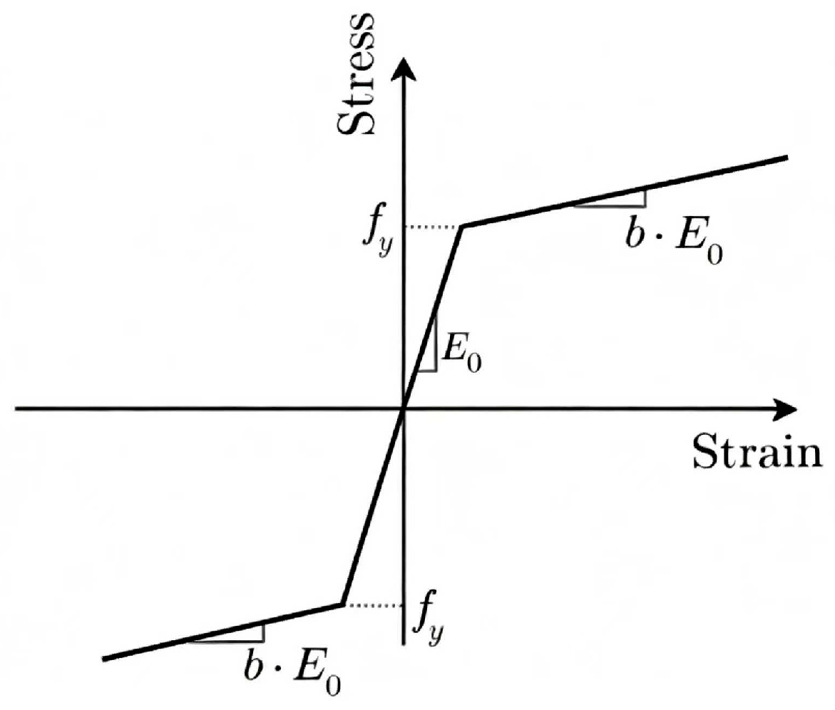
The constitutive model of reinforcing bars and the steel are established using a bifold model as shown in Figure 11 []. The slope of the second segment is taken to be 0.01 and is the modulus of elasticity of the steel.
where is the true plastic strain; is the true strain; is the true elastic strain; is the true stress; and is the elastic modulus of the reinforcement.
Figure 11.
Bilinear hardening constitutive model for steel.
2.3. Experimental Design
When using ABAQUS 6.9 for finite element analysis, the reasonableness of the boundary conditions directly affects the reasonableness of the calculation results. In this experiment, the setup of axial fixation at one end and axial displacement constraint applied at the other end is adopted, and the reference point and loading direction are shown in Figure 12. The axial compression of the beam segment at six different boundary friction coefficient levels between the rigid base and the end of the beam segment is investigated (shown in Table 4).
Figure 12.
Experimental specimen model.
Table 4.
Experimental design.
Considering that the connection bars inserted in the longitudinal holes are only temporarily stressed during the preconstruction period of the beam segment splicing (when the vertical and transverse connection screws have not yet been installed), the connection bars are not stressed after the main bracing is compressed. The diameter of the longitudinal holes is taken as a fixed value (i.e., the design value is provided in Section 2.1), and the influence of the change of hole diameter on the compressive property of the beam segment specimens is ignored. In order to study the weakening effect of the change of the diameter of the vertical and transverse connection holes on the beam segments, hole diameters of 0 mm (i.e., no vertical and transverse connection holes), 35 mm, and 45 mm were added to the design value of 40 mm (see Section 2.1). Obviously, the weakest section of the specimen (the section with the largest porosity) is located on the plane of a row of vertical connection holes. Therefore, when the vertical and transverse connection hole diameter is 35 mm, 40 mm, and 45 mm, the porosity of the weakest cross-section is 16%, 18%, and 20%, respectively. And the maximum cross-section porosity was only 0.8% when the vertical and transverse connection hole diameter is 0 mm (at this time, there were only longitudinal connection holes).
Given the beam sleeve is covered on the end of the beam segment, it should be considered an influencing factor. Based on the design value of 10 mm for the thickness of the beam sleeve in Section 2.1, three thickness levels of 0 mm (i.e., no beam sleeve), 5 mm, and 15 mm were added (The thickness of the steel plate and the angle steel in the beam sleeve in each specimen is the same).
Therefore, based on the dimensions and structures of the beam segment provided above, beam-end restraints, connection hole diameters, and beam sleeve thicknesses were selected as factors, and 4–6 levels were selected for each factor to obtain the 15 test treatments shown in Table 4.
Using the above experimental design, the following mechanical properties of the beam segment specimens under compression in numerical simulation are examined: (1) Load-carrying capacity, extracting the maximum axial load-carrying capacity (peak load) through the load-displacement curve and comparing the differences in the peak load and curve shape under different factor levels. (2) Concrete damage distribution, using the damage contour output from the CDP to identify the location of maximum compression damage and the damage value (0~1). (3) Damage pattern, observing whether stress concentration and plastic damage accumulation occur at the end holes. (4) Evaluating the sensitivity of end restraints to structural safety through the relationship between the friction coefficient and the change in load-carrying capacity.
Since concrete is the main load-carrying component of reinforced concrete beam segment, this paper mainly focuses on the damage results of concrete under axial compression and explores the influence of external protective structure on the failure location.
3. Results and Discussion
3.1. Model Validation
The validity of the finite element analysis model was determined by comparing simulated values with experimental data, as demonstrated in reference []. In this study, the accuracy of the proposed finite element analysis model was verified by comparing the calculated axial compressive bearing capacity of specimen 1 with the simulated values from this finite element analysis model.
According to Reference GB 50010-2010 [], the design value of axial compressive strength of concrete, considering the reduction factor, can be calculated with the following Equation (13):
Due to the fact that the compressive strength of concrete in finite element analysis is based on the standard value of axial compressive strength and is not multiplied by a reduction factor, the parameters in Formula (13) need to be modified in order to make the calculated values comparable to the finite element analysis values. The modifications include replacing the design value of concrete compressive strength in Formula (13) with the standard value of concrete compressive strength . Furthermore, the combined simplification factor 0.9 (accounting for the structural importance factor and load combination factor) and the member stability factor φ are ignored.
So, the axial compressive strength of specimen 1 is calculated by using Formula (14):
where N is the compressive bearing capacity of a specimen; A is the cross-sectional area of the specimen, here it is 560,000 (); is the design value of concrete compressive strength, here it is 23.4 (); is the design tensile strength of the longitudinal reinforcement, here it is 360 (); is the cross-sectional area of the longitudinal reinforcement, here it is 6080 ().
According to Formula (14), the calculated value of axial compressive capacity of the treatment 1 specimen is 15,292.8 kN, which is 1.95% higher than the finite element simulation value of 15,000 kN. This error is within the acceptable range. Therefore, it proves that the established finite element model is reliable, and it also proves that the constitutive relationship used in this study can reasonably describe the mechanical behavior of reinforced concrete structures.
3.2. Mesh Division Validation
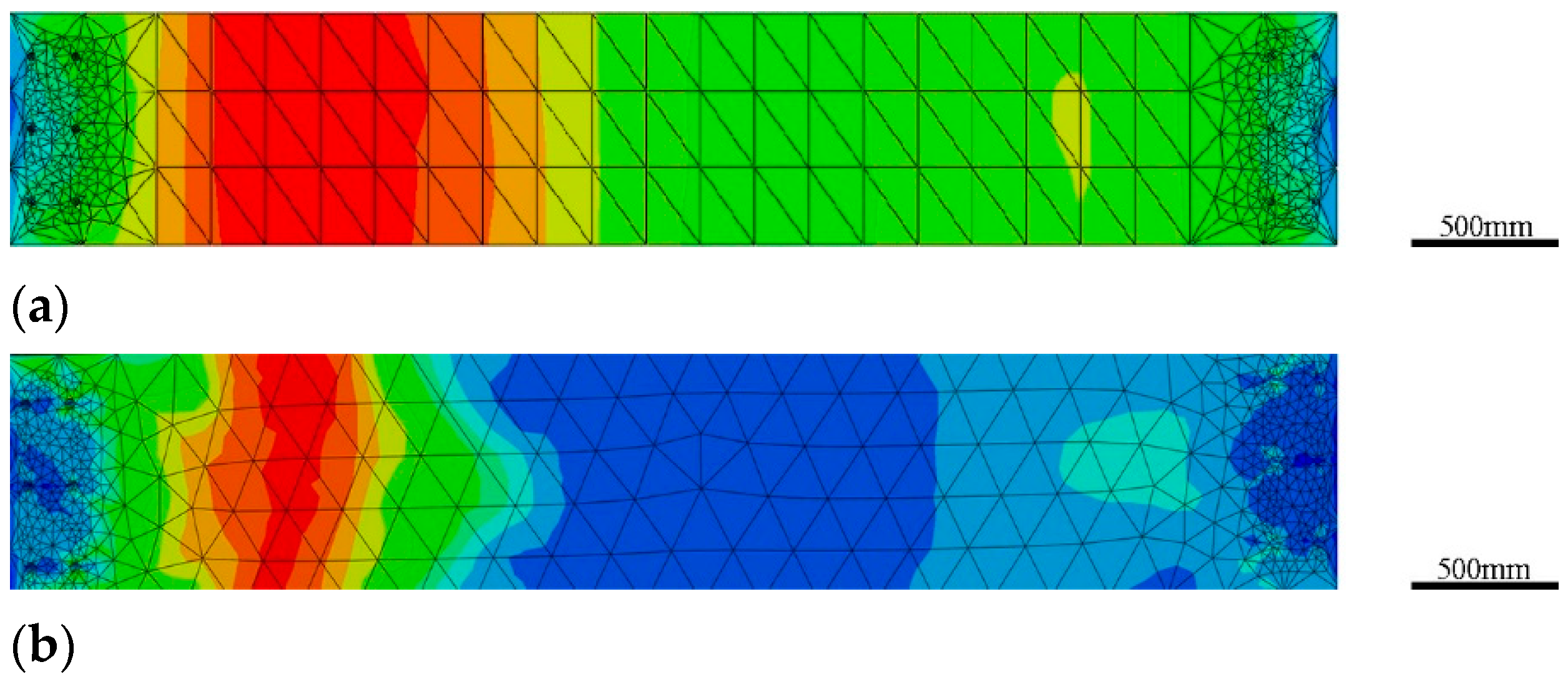
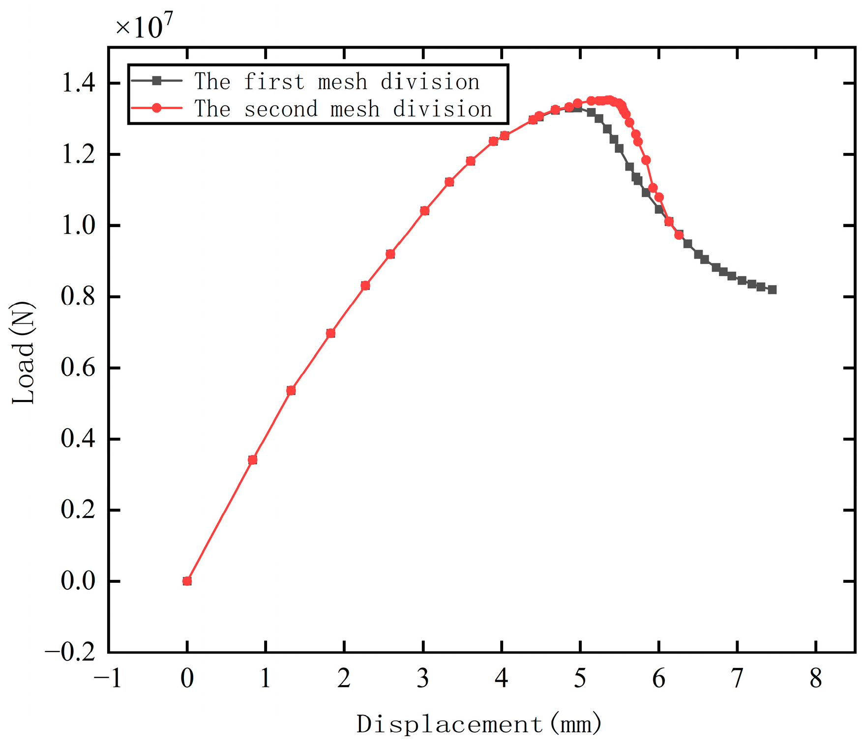
Select the finite element analysis results of treatment 1, treatment 3, and treatment 14 at different mesh sizes or shapes to verify the independence of mesh shape and mesh size from the analysis results. The peak bearing capacity of the three treatments under different mesh sizes or mesh shapes is shown in Table 5. Through comparison, it was found that mesh size and mesh shape had little effect on the peak axial bearing capacity of the specimen. The reason for this is that mesh division is based on continuous media, and the calculation of bearing capacity is based on secondary processing of node displacement. However, displacement capture accuracy is not sensitive to mesh density and shape, and peak bearing capacity fluctuates very little under different mesh shapes and sizes. The stress contour maps of the specimen under two different mesh divisions are shown in Figure 13. The axial compression load-displacement curves of the specimens under two mesh divisions are shown in Figure 14. It can be seen that the curves of the specimens with two mesh divisions are basically overlapped except for some differences in the maximum value (The peak load-bearing capacity of the first mesh is 13,300 kN, while that of the second mesh is 13,530 kN, differing by only 1.7%), and the failure location of the specimen is basically in the same area. This further indicates that the mesh division of the specimens has little effect on the finite element analysis results.
Table 5.
Axial compressive bearing capacity of the three treatments with different mesh sizes and shapes.
Figure 13.
Concrete compression damage contour map for treatment 11 at 8 mm compression displacement. (a) damage contour map of concrete with the first mesh division of treatment 11, (b) damage contour map of concrete with the second mesh division of treatment 11.
Figure 14.
Axial compression load-displacement curves for treatment 11 with two kinds of mesh divisions.
3.3. Analysis of Axial Compression of Specimen When the Boundary Is a Rigid Body Section
The boundary of the specimen in Treatment 1–5 is set as a rigid surface (represented by ‘-’ in Table 4). The pressure displacement curve of the beam section is shown in Figure 15, in which the number next to the legend represents the treatment number (the same in the following figures). As shown in Figure 15, the maximum bearing capacity of the specimen with a beam sleeve and a connecting hole (treatment 2) is about 16,500 kN, while the maximum bearing capacity of the specimen without a beam sleeve and a connecting hole (treatment 3) is about 12,500 kN. This finding that opening holes in reinforced concrete members reduce their bearing capacity is consistent with the phenomenon described in the literature [,,,,]; additionally, the law that the beam sleeve can significantly improve the bearing capacity of the specimen is consistent with the research findings in the literature [,,,,]. The curve trend of the specimen without a beam sleeve and connection hole (treatment 1) is similar to that of treatment 2. The maximum bearing capacity of treatment 1 is 15,000 kN, which is 1500 kN (about 6.3%) lower than that of treatment 2, but 2500 kN higher than that of treatment 3.
Figure 15.
Axial compression load-displacement curves for treatment 1–3.
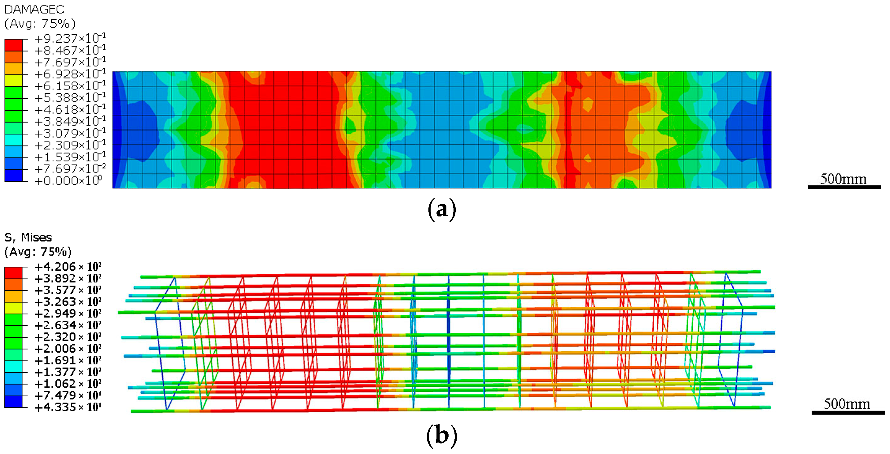
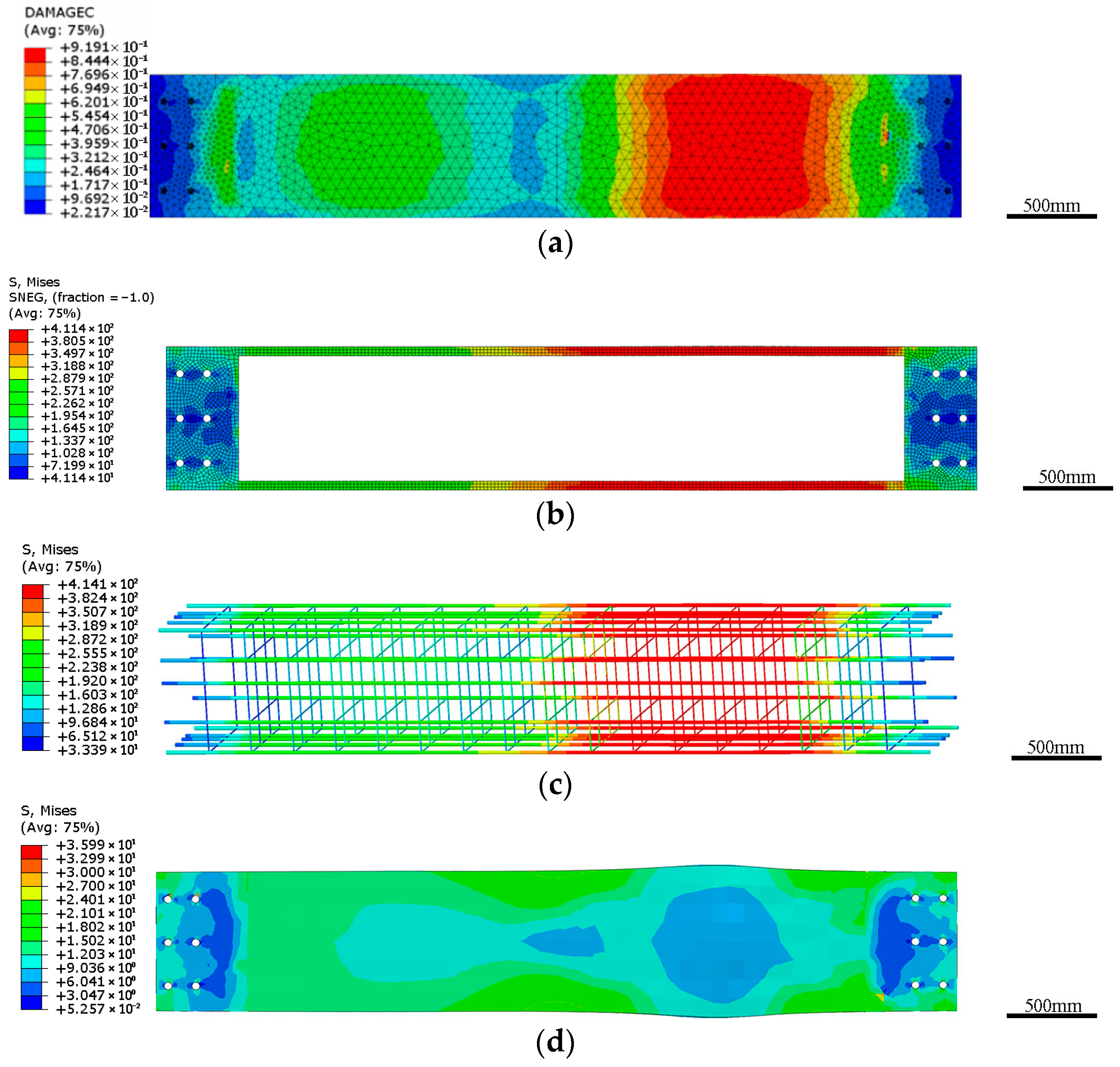
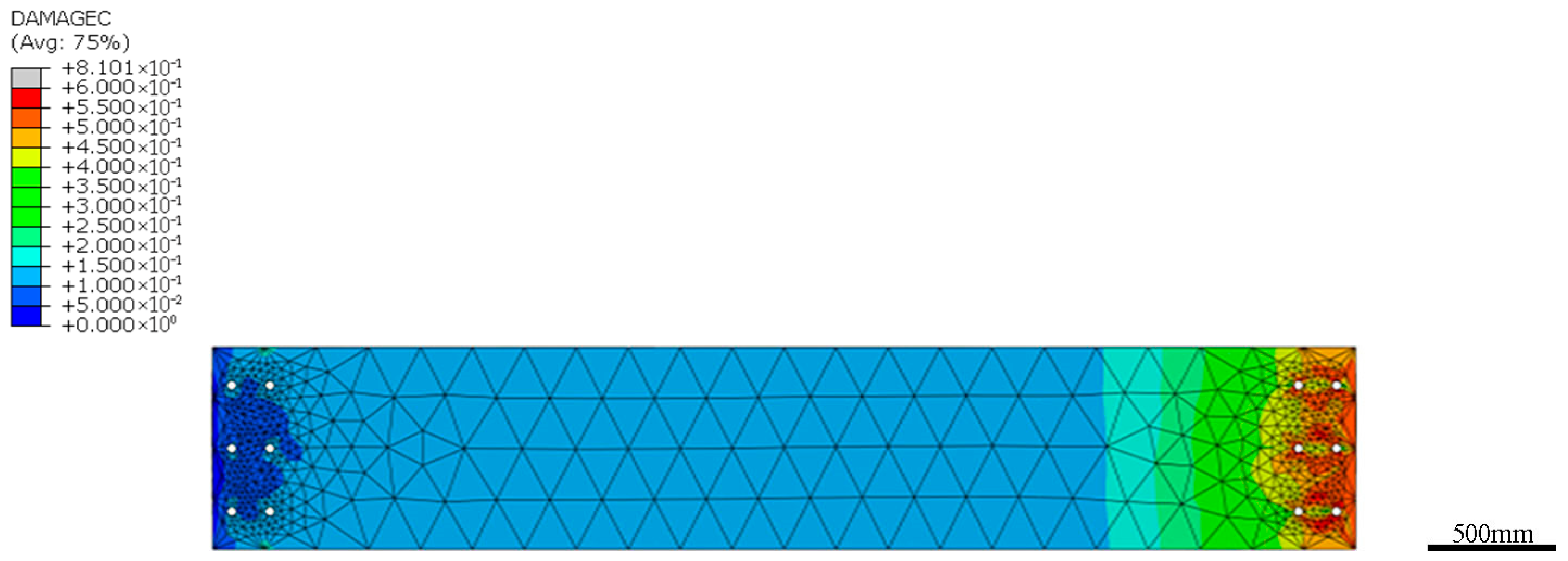
Figure 16, Figure 17 and Figure 18 present the final concrete damage contours for specimens of treatments 1–3, respectively (The stress unit (S. Mises) used in all figure legends is MPa). As shown, treatment 1 and treatment 2 exhibit extensive concrete compression damage near the final stage, with damage values reaching approximately 0.9 (indicated by the red zones in the contour maps). The maximum damage zones result in a near-complete loss of concrete functionality, leading to a sharp decline in load-bearing capacity. The end face of the beam section in treatment 1–5 can be considered as an ideal rigid section, which has a strengthening effect on the concrete near the end (called the “confinement effect”). This aligns with the findings in reference [], which indicate that transverse confinement materials can enhance the compressive strength and ductility of concrete, with externally wrapped confinement demonstrating a more pronounced improvement effect. Due to this effect, the left and right end faces of the specimens without a beam sleeve (treatment 3) had a smaller amount of plastic damage to the concrete; although the connection hole weakens the end of the beam to some extent, the failure position is not at the hole position. The maximum damage position of the specimen with the beam sleeve (treatment 2) was farther away from the end face than that of treatment 3, and the concrete damage value at the connection hole of treatment 2 was relatively smaller, indicating that the existence of beam sleeve changes the maximum damage position and enhances the safety of the area where the hole is located. As shown in the stress contour map of reinforcement, beam sleeve. and concrete in treatment 1–2 in Figure 16 and Figure 17, the maximum stress position of beam sleeve and reinforcement is consistent with the maximum damage position of concrete. From the concrete stress contour map in Figure 17d, it can be seen that the concrete at the maximum damage position has bulged, deformed, and withdrawn from the stress bearing capacity. Therefore, the follow-up study of this paper only focuses on the damage contour map of concrete. Based on the dimensions of the beam segment provided above, its slenderness ratio can be calculated to be only 6.4. According to the theory of axial compression failure of short reinforced concrete columns, its failure mode is plastic compression failure. The failure mode shown in Figure 17d conforms to this classical theory. Since all specimens used in this study have the same slenderness ratio and reinforcement arrangement, their axial compression failure modes are identical, except for the failure areas. Therefore, the failure modes of other treatments will not be reiterated in the following sections.
Figure 16.
Treatment 1 simulation results. (a) final damage contour map of concrete of treatment 1, (b) final stress contour map of reinforcement skeleton of treatment 1.
Figure 17.
Treatment 2 simulation results. (a) final damage contour map of concrete of treatment 2, (b) final stress contour map of beam sleeve of treatment 2, (c) final stress contour map of reinforcement skeleton of treatment 2, (d) final stress contour map of concrete of treatment 2.
Figure 18.
Final stress contour map of treatment 3.
3.4. Analysis of the Effect of End Friction Constraints on the Axial Compressive Mechanical Properties of Specimens with Holes
In Section 3.3, the constraint condition that the two end faces of the specimen are rigid cross-sections is relatively too strong. In practical engineering, the constraint of the end face under axial compression is not completely fixed, and relative displacement can occur in the cross-sectional direction, which means lateral displacement on the end face section is not zero. The end faces of the specimen are mainly subject to frictional restraint in the plane. It is set that the rigid base and the end face of the specimen are in face-to-face contact, and their normal direction behavior complies with hard contact, while a penalty function is used to simulate their tangential direction friction behavior. The friction coefficient between the rigid base and the end face of the specimen is set to the values shown in Table 4 (According to the Code (GB 50010-2010), when the friction coefficient between concrete and rigid base is 0.6, it can well characterize the slip between them. Therefore, this friction coefficient is used in many treatments (treatment 10–18) in this paper).
The specimen with a certain thickness of beam sleeve and a certain hole diameter only changes the position of the concrete compression damage section under different beam-end friction constraints, which has little effect on the bearing capacity displacement curve of the specimen (because the difference of the bearing capacity displacement curve between specimens is very small, some treatments are not listed in Table 4). The friction coefficient in treatment 6 is zero, and the damage contour map of the concrete in the treatment 6 specimen at a certain time in the linear loading section (just after the maximum bearing capacity) is shown in Figure 19 (Legends in Figure 20, Figure 21, Figure 22 and Figure 23 are the same). It is clear that when the lateral constraint at the end is zero, the “confinement effect” at the end is zero, and the bearing capacity of the end section in the specimen is significantly reduced. The failure section caused by the plastic compression damage of the concrete will occur at the hole section. This is consistent with the dangerous section position obtained by using the results of material mechanics analysis.
Figure 19.
Concrete compressive damage contour map of treatment 6 at a specific time.
Figure 20.
Damage contour map of concrete compressive damage at maximum load capacity of treatment 10.
Figure 21.
Damage contour map of concrete compressive damage at the moment of maximum load capacity for treatment 9.
Figure 22.
Damage contour map of concrete compressive damage at the moment of maximum load capacity for treatment 8.
Figure 23.
Damage contour map of concrete compressive damage at the moment of maximum load capacity for treatment 7.
Figure 20, Figure 21, Figure 22 and Figure 23 demonstrate the concrete compression damage contour map of the specimen at the moment of maximum load-bearing capacity when the friction coefficient is 0.6. They show that when the friction coefficient decreases from 0.6 to 0.1, with the end face friction coefficient decreasing, the location of its maximum compression damage is constantly close to the end face of the specimen, and when the coefficient of friction is 0.1, substantial damage begins to appear at the location of the holes. This phenomenon is consistent with the description of “end restraint can mitigate local damage” in the “Code for Design of Concrete Structures” (GB 50010-2010).
3.5. Influence of Hole Diameter on the Axial Compressive Mechanical Properties of Specimen Concrete
The specimens with hole diameters of 35 mm, 40 mm, and 45 mm were analyzed under axial compression (treatment 10–14). The global dimensions of the concrete solid cell mesh of the specimens were kept constant, and their reinforcement cells were also kept constant.
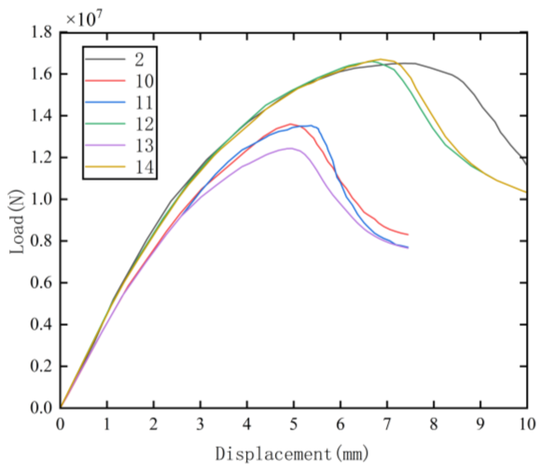
The load-displacement curves for treatment 10–14 and treatment 2 (treatment 2 is also plotted together because the end friction constraints have little effect on the peak load capacity) are shown in Figure 24. The enlargement of the hole diameter resulted in a decrease in the peak load-bearing capacity of the specimens without beam sleeves (treatment 10, 11, and 13). Specimens with hole diameters of 35 mm, 40 mm, and 45 mm exhibited peak load-carrying capacities of 13,300 kN, 12,500 kN, and 12,300 kN, respectively. These values represent reductions of approximately 11.3%, 16.7%, and 18% compared to the peak capacity of the unperforated specimen (treatment 1 in Figure 13). The results are consistent with the principle described in [,,]. Comparing the concrete damage contour map of treatment 13 in Figure 25 with that of treatment 10 in Figure 20, it can be found that the expansion of the hole diameter leads to an increase of the compression damage at the hole position at the time of maximum bearing capacity. The explanation of this phenomenon is that on the one hand, with the increase of pore size, the larger section is weakened, and on the other hand, the stress concentration phenomenon caused by the reduction of section area makes the position of hole located enter the plastic stage in advance. Figure 13b, Figure 26 and Figure 27 show the compression damage contour map of treatments 11, 10, and 13 when the axial compression displacement is 8 mm and the upper limit value of damage is 0.6 (greater than or equal to 0.6 is displayed in red). From the damage contour maps, it can be seen that the compression damage at the location of the specimen hole increases with the increase of the hole diameter, and the “confinement effect” on the boundary of the specimen with the 45 mm hole can no longer protect the cross-section near the end face. It can be seen from Figure 24 that when the specimen hole diameters of treatments 2, 12, and 14 (having the same thickness of the beam sleeve) become larger, there is no obvious difference in the bearing capacity (about 16,500 kN) of the three specimens, which is greater than the maximum bearing capacity of the specimen without the beam sleeve and without the hole (treatment 1) of 15,000 kN. By comparing the concrete damage contour map of treatment 14 in Figure 28 with that of treatment 13 in Figure 27, it can be found that due to the existence of the beam sleeve, the concrete damage at the end of the specimen is significantly reduced, and the maximum damage position is further away from the beam-end face and the area the hole is located. (Legends in Figure 25, Figure 26, Figure 27 and Figure 28 are same as Figure 19).
Figure 24.
Load-displacement curve diagram for treatment with different hole sizes.
Figure 25.
Contour map of concrete compressive damage at maximum load capacity for treatment 13.
Figure 26.
Concrete compression damage contour map for treatment 10 at 8 mm compression displacement.
Figure 27.
Concrete compression damage contour map for treatment 13 at 8 mm compression displacement.
Figure 28.
Concrete compression damage contour map for treatment 14 at 8 mm compression displacement.
3.6. Influence of Beam Sleeve Thickness on the Mechanical Properties of Specimens Subjected to Axial Compression
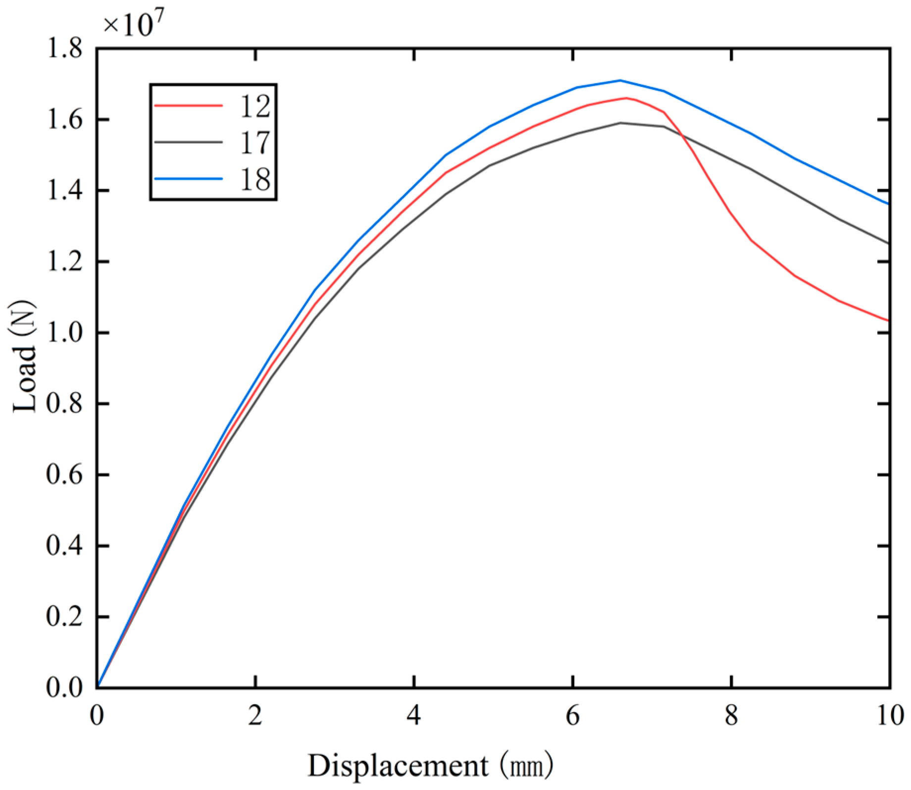
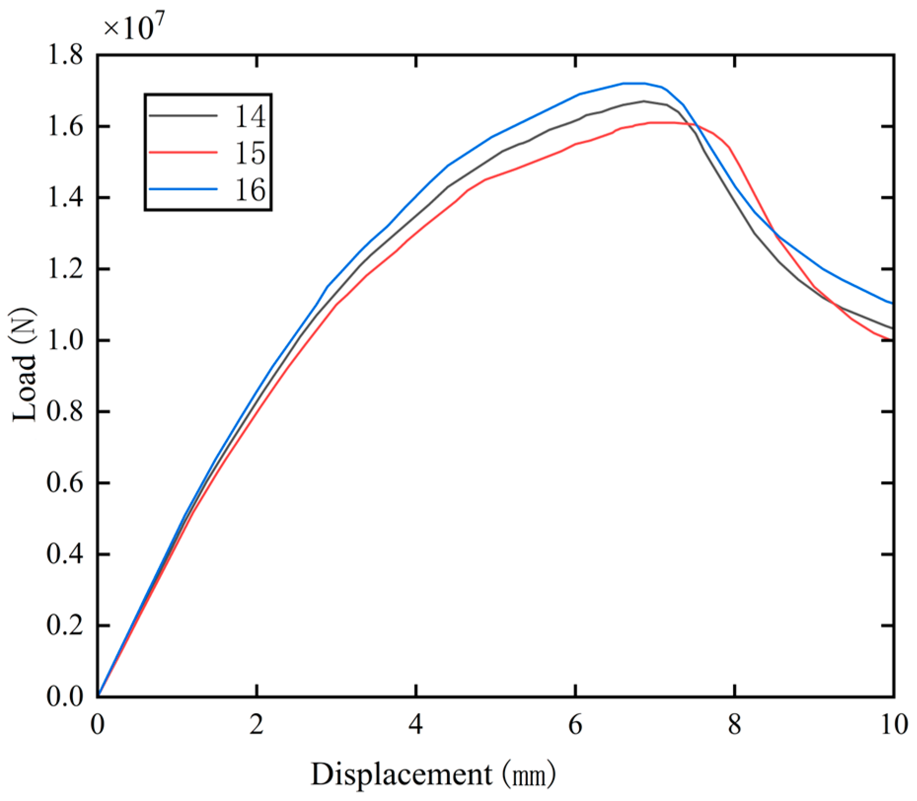
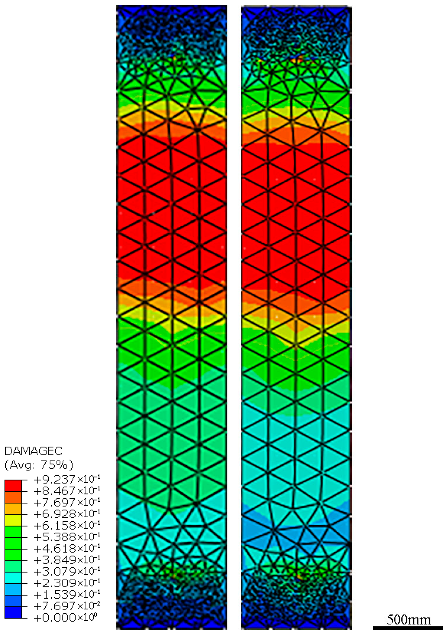
Numerical simulation results of axial compression of specimens with three different thicknesses (5 mm, 10 mm, 15 mm) of beam sleeve at three different holes diameters are presented in Figure 29, Figure 30 and Figure 31. The results show that at each hole diameter (35 mm, 40 mm, 45 mm, respectively), the maximum load capacity provided by the beam sleeve increases significantly with the increase of steel plate thickness. For example, for specimens with 40 mm holes, the peak load-carrying capacity of specimens with beam sleeves of 5 mm (treatment 4), 10 mm (treatment 2), and 15 mm (treatment 5) are 16,200 kN, 16,500 kN, and 17,600 kN, respectively, which means the peak load-carrying capacity of specimens with beam sleeve thickness of 10 mm and 15 mm are increased by 1.9% and 8.6%, respectively, compared to that of 5 mm. Meanwhile, the difference in compressive bearing capacity of specimens with different hole diameters under the same thickness of the beam sleeve is very small. For example, when the beam sleeve is 5 mm thick, the peak bearing capacities of specimens with three-hole diameters of 35 mm (treatment 17), 40 mm (treatment 4), and 45 mm (treatment 15) are 15,900 kN, 16,200 kN, and 16,100 kN, respectively. This shows that the specimen with the thinnest beam sleeve of 5 mm and the largest hole of 45 mm (treatment 15, maximum porosity of 20%) still has a peak bearing capacity of 15,000 kN, which is greater than the specimen without beam sleeve and holes (treatment 1). This result is consistent with the findings described in reference [,,,] that thin-walled steel tubes significantly improve the axial compressive bearing capacity of reinforced concrete components. Therefore, when the specimen has both a beam sleeve and beam-end holes, the thickness of the beam sleeve has a decisive impact on the compressive bearing capacity of the specimen, and the influence of holes with a diameter below a certain value can be ignored. The explanation for this phenomenon is that due to the confinement effect of the beam sleeve on the end of the beam segment, the failure position is moved from the beam end (as shown in Figure 19 and Figure 23) to the middle of the beam segment (as shown in Figure 26), and the holes in the beam segment have no effect on the bearing capacity of the beam segment. This discovery provides theoretical support for the usability of beam segment structures—that is, the confinement effect of beam sleeves on beam segments can compensate for the weakening effect of holes on beam segments. From Figure 32, it can be seen that there is little difference in the location and area of concrete compression failure at the final moment for specimens with different thicknesses of beam sleeves.
Figure 29.
Axial compression capacity displacement curves for specimens of three thicknesses of beam sleeve (40 mm holes diameter).
Figure 30.
Axial compressive strength-displacement curves of specimens under three thicknesses of beam sleeve (35 mm holes diameter).
Figure 31.
Axial compressive strength-displacement curves of specimens under three thicknesses of beam sleeve (45 mm holes diameter).
Figure 32.
Final concrete compressive damage contour map at the thicknesses of treatment 2 (left) and treatment 5 (right).
Due to the lack of relevant regulatory guidance for new technologies and the unclear impact of beam sleeves and holes on the bearing capacity of beam segments, the original beam sleeve design used in this study is relatively conservative. The design method is to not consider the confinement effect of the beam sleeve and only design the thickness of the beam sleeve based on the cross-section of the beam sleeve at the most dangerous section of the beam segment that can provide a bearing capacity greater than or equal to the weakened bearing capacity of the hole section. According to this design method, for the most dangerous section, a 10 mm thick beam sleeve can provide a bearing capacity of 235 × (0.7 × 2 + 0.8 × 2) × 0.01 = 7.05 MPa, a 5 mm thick beam sleeve can provide a bearing capacity of 3.5 MPa, and the weakening of the most dangerous section of the beam by the 45 mm hole is 23.4 × 0.7 × 0.8 × 0.2 = 2.62 MPa. So, it can be seen that if negative effects such as stress concentration at the holes are not taken into account, the original design with a 10 mm thick beam sleeve has a relatively large safety margin, and even if a 5 mm thick beam sleeve is used, safety can still be guaranteed. The numerical analysis study of this research further eliminates the worry about the detrimental effects of the holes and also indicates that the thickness of the beam sleeve can be further reduced if the confinement effect of beam sleeve on the reinforced concrete are considered.
As mentioned above, in order to facilitate the study of the influence of beam sleeve and holes on the stress of beam segments, the stress of beam segments in this paper is simplified as axial compression and the bending moment and shear force caused by self-weight are ignored. Because only the length and cross-sectional dimensions of the single beam segment were considered, it is concluded that the beam segment is in a short column compression state. This stress state is significantly different from the stress state when the beam segments are spliced into the main bracing for foundation pit engineering. In practical engineering, the main bracing (see Figure 1) is generally subjected to eccentric compression, and the bending moment and shear force caused by its own weight should be considered. The slenderness ratio should also be calculated based on the length between the two lattice columns and the cross-sectional size of the main bracing to determine whether the stability of the compression bar should be considered. Only by considering these forces comprehensively can the reinforcement and cross-sectional dimensions of the main bracing (beam segment) be designed.
4. Conclusions
Numerical simulation has been used to systematically analyze the effects of beam-end holes with four hole diameters (0 mm, 35 mm, 40 mm, 45 mm) and four thicknesses of steel beam sleeve (0 mm, 5 mm, 10 mm, 15 mm) under different end-constraint conditions on the axial compression performance of RC beam segments. The main conclusions are as follows:
- (1)
- For specimens without a steel beam sleeve, the compressive strength decreased by 11.3%, 16.7%, and 18%, respectively, when the hole diameters were 35 mm, 40 mm, and 45 mm compared to specimens without holes. Beam-end holes significantly reduced the compressive strength of beam segments without a sleeve, and the reduction in compressive strength increased with larger hole diameters.
- (2)
- In specimens with holes and steel beam sleeves of 5 mm, 10 mm, and 15 mm thickness, respectively, the compressive bearing capacity was higher than that of specimens without beam sleeves and holes. The beam sleeves exert a decisive influence on the compressive bearing capacity of the specimens, and the confinement effect of the beam sleeve on the beam segment compensated for the weakening effect caused by the holes. As the thickness of the beam sleeve increased, the bearing capacity of the beam segment increased significantly. Moreover, the presence of beam sleeves markedly reduced concrete damage at the specimen ends, shifting the location of maximum damage from the end hole regions to the mid-span of the beam segment. These findings confirm that the designs of holes in beam segment ends and beam sleeves can meet safety requirements.
- (3)
- The end restraint condition has little effect on the compressive bearing capacity of the beam segment, but it changes the location of the concrete compression-damage cross-section. As the end face friction coefficient decreases from 0.6 to 0.1, the maximum compression damage location of the beam section moves closer to the end face, and the damage at the hole location also increases gradually.
5. Prospects
The analytical methods and findings presented in this paper are useful as a guide for the design of beam segments. In the future, more factors (such as hole location, beam cover area, etc.) and levels of factors (such as more beam cover thickness and hole diameter) can be studied, and more comprehensive relevant laws can be obtained through experiments or practical verification. Developing standardized design methods based on these findings will undoubtedly promote the engineering application of the hybrid prefabricated RC-SS foundation pit bracing system.
Author Contributions
Conceptualization, J.Y.; methodology, J.Y. and T.W.; software, P.X. and T.W.; validation, J.Y., T.W. and W.Z.; formal analysis, K.X. and S.L.; investigation, T.W., K.X. and P.X.; resources, S.L.; data curation, T.W. and P.X.; writing—original draft preparation, J.Y., T.W. and P.X.; writing—review and editing, J.Y., T.W. and W.Z.; visualization, T.W. and P.X.; supervision, K.X. and S.L.; project administration, J.Y., K.X. and S.L.; funding acquisition, J.Y., W.Z., K.X. and S.L. All authors have read and agreed to the published version of the manuscript.
Funding
General Program (12072130) of National Natural Science Foundation of China and technology development project (4201/03757) provided by The First Company of China Eighth Engineering Bureau Ltd.
Institutional Review Board Statement
Not applicable.
Informed Consent Statement
Not applicable.
Data Availability Statement
The original contributions presented in this study are included in the article. Further inquiries can be directed to the corresponding author.
Acknowledgments
The authors want to thank Zhaowei Liu, Xin Liu, Yong Wang, Gang Xia, Xihong Zhang, Bin Liu, Haiyang Liu, Tianming Zhang, Shuilong Guo for their help in the whole research process.
Conflicts of Interest
Author Song Li was employed by the company The First Company of China Eighth Engineering Bureau Ltd. The remaining authors declare that the research was conducted in the absence of any commercial or financial relationships that could be construed as a potential conflict of interest. The authors declare that this study received funding from The First Company of China Eighth Engineering Bureau Ltd. (4201/03757). The funder was not involved in the study design, collection, analysis, interpretation of data, the writing of this article or the decision to submit it for publication.
References
- Shan, Y.H.; Zhang, M.J.; Guo, C.X.; Li, P.; Liu, W. A Fixed End Composed of Long Bolts and Mold Bag Concrete for Prefabricated Internal Support and Its Bearing Performancein Foundation Pit Engineering. In Proceedings of the 18th Conference of the Associated Research Centers for the Urban Underground Space, Singapore, 1–4 November 2023. [Google Scholar]
- Zhou, Y.Z.; Yang, S.Y.; Wang, S.; Xu, M.X.; Zhou, H.X. Analysis and treatment for collapse accident of a foundation pit in deep and thick sullage soft-soil area. Build. Struct. 2024, 54, 128–135. [Google Scholar]
- Ye, J.J.; Peng, Q.B.; Xiao, J.Z.; Lan, W.; Wang, J. Green demolishing technology of beams or columns with embedded holes by mechanical cutting and off-site blasting. Archit. Civ. Eng. 2023, 40, 111–117. [Google Scholar]
- Ye, J.J.; Chen, F.; Xiao, J.Z.; Cheng, D.C. Green Blasting Demolition Technology of Reinforced Concrete Structures. Blasting 2019, 36, 90–97. [Google Scholar]
- Yan, N.; Hao, Z.M.; Bai, X.Y.; Zhang, L.; Sun, L.N.; Zhang, Q.J. Force and deformation characteristics of double-row miniature pile-anchor-support combination support structure for deep foundation pit. J. Cent. South Univ. 2024, 55, 2295–2309. [Google Scholar]
- Sun, W.W.; Feng, J.; Gu, L.N. Anti-Collapse Analysis of Fabricated Steel Support System Consisting of Prestressed Fish-Bellied Beams in Excavation. Chin. J. Undergr. Space Eng. 2022, 18, 989–996. [Google Scholar]
- Hu, L.Q. Theoretical Study on the Deformation Control of Retaining Piles by Steel Support of Prestressed Fish-bellied Beams. Chin. J. Undergr. Space Eng. 2021, 17, 141–149. [Google Scholar]
- Xia, G.; Liu, B.; Qi, X.C.; Li, J.H.; Zhang, T.M.; Ye, J.J.; Wu, T.L.; Xu, K.J.; Tan, B.H.; Wang, B. Easily Dismantled Hybrid Prefabricated RC-SS Foundation Pit Bracing System and Construction Method. CN119640814A, 18 March 2025. [Google Scholar]
- Zhang, T.M.; Gu, L.; Zhou, C.Y.; Wang, L.C.; Xia, G.; Ye, J.J.; Wu, T.L.; Tan, B.H.; Xu, K.J.; Gao, Y.; et al. Hybrid Prefabricated RC-SS Foundation Pit Bracing System and Demolition Method. CN119777388A, 8 April 2025. [Google Scholar]
- Ye, J.J.; Wu, T.L.; Xu, K.J.; Liu, B.; Zhang, X.H.; Gao, P.; Wei, S.S.; Zhang, J.M.; Tan, B.H.; Xu, G.H. Prefabricated Reinforced Concrete Beam Segment for Foundation Pit Bracing and Its Pre-Fabrication Method. CN119711508A, 28 March 2025. [Google Scholar]
- Tahir, M.F.; Shabbir, F.; Ahmad, A.; Ejaz, N. Experimental and Numerical Investigation of Transverse Circular Holes on Load-Carrying Capacity of RC Columns. Iran. J. Sci. Technol.-Trans. Civ. Eng. 2021, 45, 683–696. [Google Scholar] [CrossRef]
- Campione, G.; Cucchiara, C.; Minafo, G. Effects of circular openings on the compressive behaviour of RC columns. Mater. Struct. 2015, 48, 1995–2008. [Google Scholar] [CrossRef]
- Liang, J.; Wang, Y.; Zou, W.; Wang, C.; Li, W. Axial compression performance of partially encased concrete columns with web opening. Sci. Rep. 2024, 14, 11853. [Google Scholar] [CrossRef]
- Minafo, G. Load-carrying capacity of axially-loaded RC members with circular openings. Eng. Struct. 2012, 41, 136–145. [Google Scholar] [CrossRef]
- Yang, X. Study on Mechanical Performance and Reinforced Method of Opening at the Beam End in Existing Reinforced Concrete Frame Structure; Suzhou University of Science and Technology: Suzhou, China, 2022. [Google Scholar]
- Hu, Q.; Jia, S.; Wu, H.; Wang, T. Experimental Research of Axial Compression Bearing Capacity on RC Columns Strengthened with Angle Steel and Self-Compacting Concrete. Int. J. Steel Struct. 2022, 22, 253–262. [Google Scholar] [CrossRef]
- Han, L.H.; Liu, W.; Yang, Y.F. Behavior of thin walled steel tube confined concrete stub columns subjected to axial local compression. Thin-Walled Struct. 2008, 46, 155–164. [Google Scholar] [CrossRef]
- Liu, J.; Abdullah, J.A.; Zhang, S. Hysteretic behavior and design of square tubed reinforced and steel reinforced concrete (STRC and/or STSRC) short columns. Thin-Walled Struct. 2011, 49, 874–888. [Google Scholar] [CrossRef]
- Lai, M.H.; Ho, J.C.M. Axial strengthening of thin-walled concrete-filled-steel-tube columns by circular steel jackets. Thin-Walled Struct. 2015, 97, 11–21. [Google Scholar] [CrossRef]
- Li, X.Z.; Zhang, S.M.; Tao, Y.; Zhang, B. Numerical Study on the Axial Compressive Behavior of Steel-Tube-Confined Concrete-Filled Steel Tubes. Materials 2024, 17, 155. [Google Scholar]
- Choi, E.; Utui, N.; Kim, H.S. Experimental and analytical investigations on debonding of hybrid FRPs for flexural strengthening of RC beams. Compos. Part B-Eng. 2013, 45, 248–256. [Google Scholar]
- Kim, H.S.; Shin, Y.S. Flexural behavior of reinforced concrete (RC) beams retrofitted with hybrid fiber reinforced polymers (FRPs) under sustaining loads. Compos. Struct. 2011, 93, 802–811. [Google Scholar] [CrossRef]
- Saini, A.; Prakash, S.S. Analytical study on the effectiveness of hybrid FRP strengthening on behaviour of slender reinforced concrete square columns. Structures 2021, 33, 4218–4242. [Google Scholar] [CrossRef]
- Pham, T.M.; Doan, L.V.; Hadi, M.N.S. Strengthening square reinforced concrete columns by circularisation and FRP confinement. Constr. Build. Mater. 2013, 49, 490–499. [Google Scholar] [CrossRef]
- Hu, T.Y.; Zhang, H.; Zhou, J.T. Machine learning-based model for recognizing the failure modes of FRP-strengthened RC beams in flexure. Case Stud. Constr. Mater. 2023, 18, e02076. [Google Scholar] [CrossRef]
- Abuodeh, O.R.; Abdalla, J.A.; Hawileh, R.A. Prediction of shear strength and behavior of RC beams strengthened with externally bonded FRP sheets using machine learning techniques. Compos. Struct. 2020, 234, 111698. [Google Scholar] [CrossRef]
- Lu, Y.Y.; Hu, L.; Li, S.; Wang, K.-H. Experimental study and analysis on fatigue stiffness of RC beams strengthened with CFRP and steel plate. J. Cent. South Univ. 2016, 23, 701–707. [Google Scholar] [CrossRef]
- Lin, Y.; Wei, Y.; Gong, Z.H.; Xu, W.; Zhao, K. Flexural Behavior of an RC Beam Externally Strengthened with a Steel- and CFRP-Based Method. Appl. Sci. 2024, 14, 9281. [Google Scholar] [CrossRef]
- Liu, Y.L.; Hong, J.Q.; Deng, J.; Guo, D.; Dai, J.-G. Structural performance of RC beams strengthened with hybrid bonded CFRP. J. Build. Eng. 2024, 88, 109–178. [Google Scholar] [CrossRef]
- Hadi, M.N.S.; Pham, T.M.; Lei, X. New Method of Strengthening Reinforced Concrete Square Columns by Circularizing and Wrapping with Fiber-Reinforced Polymer or Steel Straps. J. Compos. Constr. 2013, 17, 229–238. [Google Scholar] [CrossRef]
- Yan, F.; Lin, Z.B. New strategy for anchorage reliability assessment of GFRP bars to concrete using hybrid artificial neural network with genetic algorithm. Compos. Part B-Eng. 2016, 92, 420–433. [Google Scholar] [CrossRef]
- Zhang, T.; Hou, Z.; Li, X.; Chen, Q. Research on the calculation of model parameters for concrete plastic damage model in ABAQUS. Chin. J. Comput. Mech. 2024, 41, 1130–1137. [Google Scholar]
- Zeng, Y.; Hu, M. Calculation Transformation and Calibration of ABAQUS Concrete Plastic Damage Constitutive Model. Water Resour. Power 2019, 37, 106–109. [Google Scholar]
- Zhang, T. Evaluation and Application of Typical Material Models Used in FE Modelling Under Monotonic and Cyclic Loading Conditions; Kunming University of Science And Technology: Kunming, China, 2020. [Google Scholar]
- Walraven, J. Fib Model Code for Concrete Structures 2010: Mastering challenges and encountering new ones. Struct. Concr. J. FIB 2013, 14, 3–9. [Google Scholar] [CrossRef]
- Yang, F.; Dong, X.; Zhou, S.; Huang, Y.C. ABAQUS Concrete Plastic Damage Factor Calculation Method and Application Research. Sichuan Archit. 2017, 37, 173–177. [Google Scholar]
- GB 50010-2010; Code for Design of Concrete Structures. China Architecture & Building Press: Beijing, China, 2011.
- Zhang, T.; Hou, Z.; Chen, Q.; Li, X.; Fang, Y.; Zhang, S.; Sun, W. A novel damage model integrated into the elastoplastic constitutive model and numerical simulations of reinforced concrete structures under cyclic loading. J. Build. Eng. 2024, 84, 108–670. [Google Scholar] [CrossRef]
- Bazant, Z.P.; Oh, B.H. Crack band theory for fracture of concrete. Matériaux Constr. 1983, 16, 155–177. [Google Scholar] [CrossRef]
- Li, J.; Chen, J. Stochastic Dynamics of Structures; John Wiley & Sons: Hoboken, NJ, USA, 2009. [Google Scholar]
- D’amato, M.; Braga, F.; Gigliotti, R.; Kunnath, S.; Laterza, M. A numerical general-purpose confinement model for non-linear analysis of R/C members. Comput. Struct. 2012, 102, 64–75. [Google Scholar] [CrossRef]
Disclaimer/Publisher’s Note: The statements, opinions and data contained in all publications are solely those of the individual author(s) and contributor(s) and not of MDPI and/or the editor(s). MDPI and/or the editor(s) disclaim responsibility for any injury to people or property resulting from any ideas, methods, instructions or products referred to in the content. |
© 2025 by the authors. Licensee MDPI, Basel, Switzerland. This article is an open access article distributed under the terms and conditions of the Creative Commons Attribution (CC BY) license (https://creativecommons.org/licenses/by/4.0/).