Abstract
To optimize the support performance of rock bolts in high-stress environments, this study employs the ANSYS (Version 2022 R2) finite element numerical simulation method to systematically investigate the influence of bolt geometrical parameters (rib spacing, rib height, and bolt diameter) on the stress state of the anchoring system. A bolt–resin–sleeve model was established to analyze Mises equivalent stress distribution and peaks under a 150 kN pull-out load. The simulation results indicate that a rib spacing of 36 mm effectively promotes the diffusion of pre-stress into deeper regions, with peak stress in the bolt rod and resin ring increasing by 34.42% and 61.64%, respectively, compared to a spacing of 12 mm. Further increase in rib spacing provides limited enhancement in peak stress. A rib height of 1.0 mm achieves optimal system performance without excessively compromising the interfacial stress level. Increasing the diameter to 22 mm raised peak stress in the bolt, sleeve, and resin by 14.19%, 30.48%, and 50.77%, respectively, compared to 18 mm, balancing load capacity and material use efficiently. The optimal parameter set (36 mm spacing, 1.0 mm height, and 22 mm diameter) was validated in a field trial in Zhongmacun Mine’s 3903 East Transportation Bottom Drainage Roadway. Monitoring recorded maximum roof subsidence of 102.9 mm, stabilizing within 25 days (daily deformation < 0.2 mm), confirming the excellent performance of the bolt support system with this parameter combination in high-stress roadways. This study provides a theoretical basis and engineering reference for the optimal design of high-performance rock bolts.
1. Introduction
Rock bolt support is a widely employed method in coal mine roadway support, renowned for its excellent impact resistance [,]. As coal mining operations in China progressively extend to greater depths, roadway surrounding rock is subjected to increasingly higher stresses and more complex geological conditions, significantly escalating the challenges associated with roadway support [,,]. The mechanical properties of the bolt body represent a critical factor influencing the effectiveness of surrounding rock control [,,]. Under conditions characterized by “high ground stress, high geothermal temperature, high karst water pressure, and strong mining disturbance” (“three highs and one disturbance”), the demands on the mechanical performance of rock bolts for surrounding rock control become even more stringent [,,].
The surface morphology of deformed rock bolts significantly influences their mechanical and anchorage performance [,]. Key geometrical parameters defining this morphology include bolt diameter, rib type, rib height, rib width, and rib spacing [,,]. Numerous studies have explored the relationship between these geometrical parameters and anchorage performance, primarily through the analysis of pull-out force [,,]. Investigating the relationship between rib spacing and anchorage performance, Aziz et al. conducted pull-out tests on deformed bars with a rib height of 1.35 mm and varying rib spacings of 12.5, 25, 37.5, and 50 mm. Their results indicated a significant increase in pull-out force with increasing rib spacing; however, a declining trend was observed when the spacing exceeded 37.5 mm [,,,,,]. Similarly, Kang Hongpu et al. performed pull-out tests on anchorage specimens with a rib height of 1.42 mm and transverse rib spacings of 11.05, 22.10, 33.15, and 44.20 mm. Their findings also demonstrated an initial increase followed by a decrease in pull-out force with increasing rib spacing, reaching a maximum at a spacing of 33.15 mm [,]. Regarding the relationship between rib height and anchorage performance, Ren Shuo conducted comparative tests on bolts with three different combinations of rib spacing and height. The study revealed that, for a constant rib spacing, the pull-out force increased with greater rib height. However, the rate of this increase gradually diminished when the rib height became excessively large []. Using numerical simulation methods, Lin Jian et al. simulated pull-out tests for bolts with rib heights of 0.4, 0.8, 1.2, 1.6, and 2.0 mm. The simulation results showed that the pull-out force required to extract the bolt increased with greater rib height. Notably, the increase magnitude in pull-out force became relatively small once the rib height reached or exceeded 1.20 mm [], which aligns with the experimental findings of Ren Shuo. Liu Yaxin et al. employed ABAQUS to establish axisymmetric and plane-symmetric models of rock bolt pull-out, analyzing the effects of rib spacing, height, width, and shape on interface stress distribution and damage evolution. Their findings highlight that rational rib parameter design can significantly enhance anchorage performance by improving mechanical interlocking and stress transfer mechanisms [,].
While the aforementioned research has yielded substantial theoretical and practical achievements, studies focusing on the stress states of both the bolt and the anchoring agent (e.g., resin) under varying geometrical parameters during pull-out tests remain relatively scarce. This paper employs ANSYS Finite Element Method (FEM) numerical simulation to investigate the relationship between bolt rib spacing, rib height, bolt diameter, and the stress state within the anchoring system. The aim is to propose reasonable values for these critical geometrical parameters. Furthermore, the anchorage performance of bolts optimized with these parameters will be validated through a field industrial trial, ultimately providing an optimized strategy for the design of high-performance rock bolts.
2. Simulation Methods
2.1. ANSYS Finite Element Model
The finite element simulations in this study were performed using ANSYS software (Version 2022 R2). The bond-slip behavior at the bolt–anchoring agent interface was simulated using cohesive zone elements. The bolt and steel sleeve were modeled using the SOLID95 element, while the anchoring agent (resin) was modeled with the SOLID165 element. The interface between the bolt body and the anchoring agent was simulated using CONTA174 and TARGE170 surface-to-surface contact elements (zero-thickness contact elements). The use of these elements allows for a more realistic representation of the mechanical properties at the interface between the bolt and the anchoring agent [,].
The model specifically simulated the anchorage segment with a length of 100 mm, which represents the critical load-transfer zone. In terms of boundary conditions and loading: the end of the steel sleeve opposite to the loading end was fully fixed (all degrees of freedom constrained), simulating the restraint provided by the surrounding rock mass. A displacement-controlled tensile load was applied to the free end of the bolt rod. This setup effectively replicates the core mechanical behavior observed in standard pull-out tests, focusing on the stress interaction within the bolt–resin–sleeve system. The free length of the bolt outside the anchorage and the bearing plate were not modeled, as the study’s focus was on the interface behavior within the anchored section.
The complete geometrical dimensions of the baseline model were as follows: bolt diameter of 22 mm, anchorage length of 100 mm, resin ring thickness of 5 mm, and steel sleeve outer diameter of 32 mm. The models of the various materials and the final established anchorage model are shown in Figure 1.
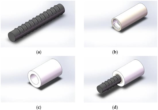
Figure 1.
Model of the left-hand thread rock bolt anchoring system: (a) Rock bolt model; (b) Resin ring model; (c) Steel sleeve model; (d) Left-hand threaded anchorage model.
2.2. Material Properties and Contact Types
After constructing the numerical model, the mechanical properties of the anchoring agent (resin ring), steel sleeve, and threaded steel anchor rod were defined according to laboratory test results [,], as listed in Table 1. The simulation assumed no failure at the interface between the anchoring agent and the steel sleeve; therefore, the contact type for the sleeve–resin ring interface was set as “Bonded”. The contact between the resin ring and the bolt body was defined as “Standard”, with a friction coefficient set to 0.2.

Table 1.
Mechanical parameters of the anchoring model.
2.3. Meshing, Boundary Conditions, and Loading
During meshing, second-order elements (SOLID95 for the bolt and sleeve, SOLID165 for the resin) were employed to enhance computational accuracy. The minimum global element size was set to 1.2 mm. Crucially, local mesh refinement was applied around the bolt ribs to accurately capture stress concentrations. For the smallest rib height of 0.7 mm, the element size in this region was refined to 0.2 mm, ensuring at least three elements across the rib height. Similarly, for the 1.0 mm rib height, a refined element size of 0.3 mm was used. This approach guarantees the resolution of stress gradients even in the most critical regions. Displacement constraints were applied to the nodes at the bottom of the steel sleeve, restricting movement in all directions to zero. Subsequently, a step-wise axial pull-out load was applied to the end of the bolt until the total load reached 150 kN.
2.4. Numerical Simulation Scheme
The simulation experiments in this study utilized the control variable method to investigate the influence of bolt diameter, transverse rib spacing, and rib height on the stress distribution within the bolt body, the resin ring, and the outer wall of the sleeve in the anchorage segment. The pull-out test scheme was configured as follows:
- (1)
- The bolt transverse rib spacing was set to 12 mm, 24 mm, 36 mm, and 48 mm, respectively, while other geometrical parameters of the bolt remained constant;
- (2)
- The bolt transverse rib height was set to 0.7 mm, 1.0 mm, 1.3 mm, and 1.6 mm, respectively, while other geometrical parameters of the bolt remained constant;
- (3)
- The bolt diameter was set to 18 mm, 20 mm, 22 mm, and 24 mm, respectively, while other geometrical parameters of the bolt remained constant.
3. Simulation Results and Discussion
3.1. Numerical Simulation of Bolt Pull-Out Tests with Different Rib Spacings
The anchorage length, rib height, rib width, and bolt diameter were set to 100 mm, 1.6 mm, 8 mm, and 22 mm, respectively. Pull-out tests were simulated for bolts with transverse rib spacings of 12 mm (8 ribs in the anchorage segment), 24 mm (4 ribs), 36 mm (2 ribs), and 48 mm (2 ribs). The nephograms of the Mises equivalent stress distribution within the anchorage system at a pull-out force of 150 kN were obtained (Figure 2, Figure 3 and Figure 4), along with the corresponding stress curves (Figure 5, Figure 6 and Figure 7).
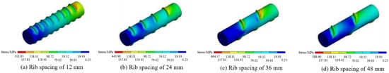
Figure 2.
Nephogram of Mises equivalent stress on the bolt rod under different rib spacings.
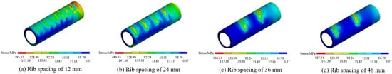
Figure 3.
Nephogram of Mises equivalent stress at axial monitoring points of the resin ring under different rib spacings.
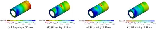
Figure 4.
Nephogram of Mises equivalent stress on the outer wall of the sleeve under different rib spacings.
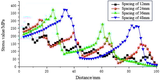
Figure 5.
Mises equivalent stress curve at monitoring points on the bolt rod under different rib spacings.
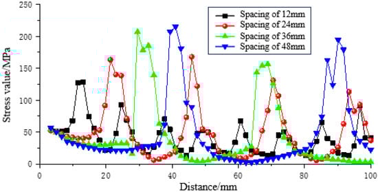
Figure 6.
Stress curve at axial monitoring points of the resin ring under different rib spacings.
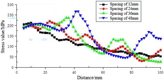
Figure 7.
Stress curve at monitoring points on the outer wall of the sleeve under different rib spacings.
3.1.1. Influence of Increased Rib Spacing on Stress Distribution Morphology
The stress distribution within the bolt body in the anchorage segment is shown in Figure 2. The maximum Mises equivalent stress occurred on the side of the bolt ribs closest to the loading end, and the stress magnitude decreased gradually along the axis from the loading end towards the opposite end. As the rib spacing increased, the maximum equivalent stress propagated deeper into the bolt body and its magnitude increased. This deeper stress propagation is beneficial for the diffusion of pre-stress into the deeper parts of the borehole, allowing the full-length pre-stressed anchorage to utilize its supporting function more effectively.
The stress distribution within the resin ring of the anchorage segment is shown in Figure 3. The maximum equivalent stress in the anchoring agent consistently occurred at the grooves where the bolt ribs contact the agent, and the stress decreased from the loading end towards the opposite end. At a rib spacing of 12 mm, the tensile stress distribution within the numerical grooves between ribs was relatively uniform. As the rib spacing increased, the uniformity of the stress distribution within these grooves decreased, and the stress concentration effect became more pronounced. This indicates that a larger rib spacing allows the tensile force experienced by the anchoring agent to propagate deeper into the borehole after the bolt is subjected to pulling force.
The stress distribution on the outer wall of the sleeve in the anchorage segment is shown in Figure 4. The equivalent stress on the sleeve’s outer wall decreased gradually from the loading end towards the opposite end, with the maximum stress located on the outer wall near the loading end. As the bolt’s rib spacing increased, the stress on the sleeve’s outer wall changed significantly: the area of lower stress (below 118.41 MPa) decreased, while the area of higher stress (above 118.41 MPa) increased. However, compared to the spacing of 36 mm, the high-stress distribution area on the sleeve outer wall for the 48 mm spacing showed a slight decrease.
3.1.2. Influence of Rib Spacing on Stress Peak Values and Growth Patterns
The stress distribution curve along the axial direction on the base circle surface of the bolt body at the rib side within the anchorage segment, based on monitoring points, is shown in Figure 5. Under the 150 kN load, the maximum equivalent stresses on the bolt body surface for rib spacings of 12 mm, 24 mm, 36 mm, and 48 mm were 276.56 MPa, 305.16 MPa, 371.74 MPa, and 372.00 MPa, respectively. The growth rates compared to the 12 mm spacing were 10.34%, 34.42%, and 34.51%, respectively. The maximum equivalent stress on the bolt body surface increased significantly for spacings of 12 mm, 24 mm, and 36 mm. In contrast, no substantial increase was observed when the spacing increased from 36 mm to 48 mm.
The stress distribution curve along the axial direction on the inner wall surface of the resin ring at the bolt rib side within the anchorage segment is shown in Figure 6. The maximum equivalent stresses on the inner wall of the resin ring for spacings of 12 mm, 24 mm, 36 mm, and 48 mm were 127.96 MPa, 167.69 MPa, 206.84 MPa, and 215.09 MPa, respectively. The maximum growth rate reached 68.09% compared to the 12 mm spacing. This indicates that the peak stress in the resin ring is highly sensitive to changes in rib spacing.
As shown in Figure 7, the maximum equivalent stresses on the outer wall of the sleeve in the anchorage segment for the four rib spacings were 188.34 MPa, 193.59 MPa, 204.11 MPa, and 213.74 MPa, respectively, with a maximum growth rate of 13.49%. Compared to the bolt body and the anchoring agent, the increase in maximum stress on the outer wall of the sleeve was relatively gradual.
Comprehensively considering the equivalent stress distribution patterns and the variation laws of stress peaks in the anchorage system under different rib spacings, a rib spacing of 36 mm is determined to be the most reasonable under the conditions of this study.
3.2. Numerical Simulation of Bolt Pull-Out Tests with Different Rib Heights
The anchorage length, transverse rib spacing, rib width, and bolt diameter were fixed at 100 mm, 36 mm, 8 mm, and 22 mm, respectively. The nephograms of the equivalent stress distribution (Figure 8, Figure 9 and Figure 10) and the equivalent stress distribution curves (Figure 11) of the anchorage system under a pull-out force of 150 kN were obtained.
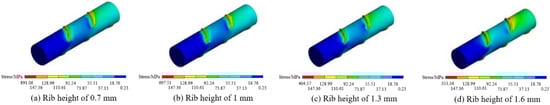
Figure 8.
Nephogram of Mises equivalent stress on the bolt rod under different rib heights.
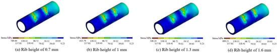
Figure 9.
Nephogram of Mises equivalent stress at axial monitoring points of the resin ring under different rib heights.
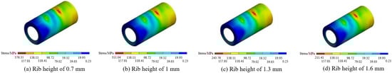
Figure 10.
Nephogram of Mises equivalent stress on the outer wall of the sleeve under different rib heights.
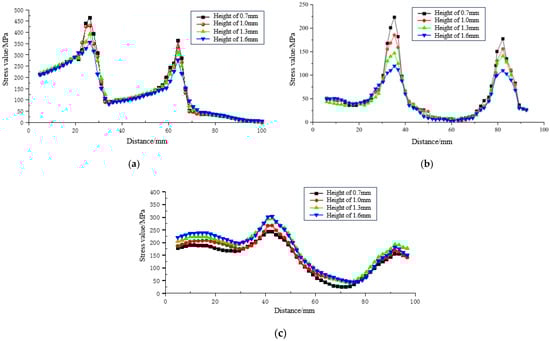
Figure 11.
Stress curve at system monitoring points under different rib heights: (a) Stress curve at monitoring points on the bolt rod; (b) Stress curve at monitoring points in the resin ring; (c) Stress curve at monitoring points on the sleeve.
3.2.1. Weakening Effect of Rib Height on Stress Distribution
The stress distribution in the bolt body within the anchorage segment is shown in Figure 8. As the rib height increased, the area of the high-stress zone (>147.36 MPa) on both sides of the ribs decreased, which is unfavorable for pre-stress diffusion and makes it more difficult for the pre-stressed bolt to exert its anchoring effect.
The stress distribution in the resin ring of the anchorage segment is shown in Figure 9, with the maximum stress located at the rib grooves. The area of the high-stress zone (147.31 MPa) gradually decreased with increasing rib height, which is detrimental to pre-stress diffusion.
The stress distribution on the outer wall of the sleeve in the anchorage segment is shown in Figure 10. The equivalent stress value decreased from the loading end towards the opposite end. The variation trend in the distribution area of the high-stress zone on the sleeve outer wall was not significant and was less affected by changes in rib height.
3.2.2. Attenuation Law of Rib Height on Stress Levels
As shown in Figure 11a,b, as the rib height increased from 0.7 mm to 1.6 mm, the maximum stress in the bolt body decreased from 464.74 MPa to 356.41 MPa (a reduction of 23.31%), and the maximum stress in the resin ring decreased from 223.23 MPa to 119.74 MPa (a reduction of 46.36%). This indicates a significant negative correlation between the peak stresses in the bolt body and resin ring and the rib height. However, Figure 11c shows that the peak stress in the sleeve increased from 243.22 MPa to 303 MPa, exhibiting an opposite growth trend.
Comparison reveals that when the rib height increased from 0.7 mm to 1.0 mm, the reductions in stress for the bolt body and resin (7.55%, 16.97%) were relatively moderate, while the stress in the sleeve began to increase effectively. Therefore, after comprehensive consideration, a rib height of 1.0 mm is determined to be the optimal value under the conditions of this study.
3.3. Numerical Simulation of Bolt Pull-Out Tests with Different Bolt Diameters
The anchorage length, transverse rib spacing, rib width, and rib height were fixed at 100 mm, 36 mm, 9 mm, and 1 mm, respectively. The nephograms of the equivalent stress distribution (Figure 12, Figure 13 and Figure 14) and the equivalent stress distribution curves (Figure 15) of the anchorage system were obtained.
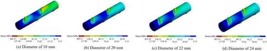
Figure 12.
Nephogram of Mises equivalent stress on the bolt rod under different bolt diameters.
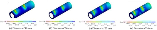
Figure 13.
Nephogram of Mises equivalent stress at axial monitoring points of the resin ring under different bolt diameters.
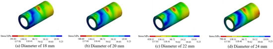
Figure 14.
Nephogram of Mises equivalent stress on the outer wall of the sleeve under different bolt diameters.
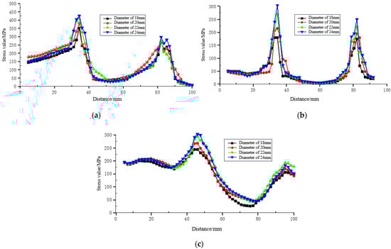
Figure 15.
Stress curve at system monitoring points under different bolt diameters: (a) Stress curve at monitoring points on the bolt rod; (b) Stress curve at monitoring points in the resin ring; (c) Stress curve at monitoring points on the sleeve.
3.3.1. Strengthening Effect of Bolt Diameter on System Stress Distribution
As shown in Figure 12, the area of the high-stress zone on the bolt body expanded with increasing diameter. This implies that a larger bolt body can withstand and transfer higher loads, thereby enhancing the overall load-bearing capacity of the bolt.
Figure 13 indicates that larger diameters improve stress distribution in the resin ring. Although the maximum stress value increased, the distribution of the high-stress zone became more expansive. This suggests that the larger contact area improves the stress state of the anchoring agent, leading to more uniform load transfer, which is beneficial for delaying plastic failure and interfacial slip of the resin.
As shown in Figure 14, similar to the effect of rib height, increasing the bolt diameter raised the overall stress value on the sleeve outer wall but had a limited impact on its stress distribution morphology. The variation trend in the distribution area of the high-stress zone on the sleeve outer wall was not significant.
3.3.2. Enhancement Efficiency of Bolt Diameter on Stress Growth in Various Components
As shown in Figure 15a,c, the maximum stress in the bolt body increased steadily from 351.58 MPa at a diameter of 18 mm to 435.83 MPa at 24 mm, an increase of 18.74%. The maximum stress in the sleeve also increased steadily from 232.22 MPa to 303 MPa. This indicates that within this parameter range, increasing the diameter can effectively and linearly improve the strength utilization of the bolt body and the sleeve itself.
Figure 15b shows that the stress increase in the resin ring was the most drastic, with the peak stress jumping from 179.59 MPa to 304.1 MPa (an increase of 69.69%). However, when the diameter increased from 20 mm to 22 mm, the stress increase was 50.77%, while the increase slowed down to 20.02% when the diameter increased from 22 mm to 24 mm. This indicates the existence of an efficiency inflection point (approximately 22 mm), beyond which further increasing the bolt diameter has a diminished effect on enhancing the stress in the resin ring.
Considering factors such as load-bearing capacity, drilling and construction costs, and material utilization efficiency, a bolt diameter of 22 mm is determined to be the optimal design value under the conditions of this study.
The comprehensive data in Table 2 allows for a direct comparison of the stress states under different geometrical parameters against the material’s yield strength within the context of this study. For rib spacing, the configuration of 36 mm achieves a high stress utilization of 92.2% without exceeding the yield strength under the defined loading and boundary conditions, indicating an efficient use of the bolt’s elastic capacity. Regarding rib height, the 1.0 mm configuration strikes an optimal balance for the modeled system, maintaining effective load transfer (106.6% utilization, implying beneficial local yielding) while preventing excessive stress reduction in the resin. For the bolt diameter, the 22 mm version also operates at a stress level (106.6% utilization) that fully engages the material’s capacity within the simulated framework, justifying its selection as the optimal diameter under these specific conditions.
Table 2.
Summary of maximum Mises equivalent stress under different geometrical parameters.
4. Field Application and Verification
To validate the practical support effectiveness of the optimal bolt geometrical parameters (rib spacing, rib height, bolt diameter) obtained from the aforementioned numerical simulations, an industrial field trial was conducted in the 3903 East Transportation Bottom Drainage Roadway at Zhongmacun Mine, owned by Henan Energy Jiaozuo Coal Co., Ltd. (Jiaozuo, China). The 3903 roadway has a designed length of 1464 m and is situated at a depth of approximately 500 m. The surrounding strata primarily consist of interbedded sandy mudstone and fine sandstone, characterized by relatively fractured rock mass, well-developed joint fissures, and distinct soft rock properties. During roadway excavation, the area was significantly affected by mining activities, resulting in substantial deformation pressure on the surrounding rock, making it a typical high-stress roadway environment. The lithological profile of the surrounding rock strata is shown in Figure 16. The roadway is located within the L8 limestone of the Taiyuan Formation, a typical confined aquifer. To prevent water inflow and ensure construction safety, pre-grouting and waterproof reinforcement were carried out ahead of excavation, effectively reducing the permeability of the surrounding rock. The groundwater in this area is weakly alkaline and does not contain aggressive or corrosive chemical components that could affect the rock bolt support system. Therefore, the influence of groundwater on the long-term bearing performance of bolts is mainly physical rather than chemical in nature. Overall, the hydrogeological conditions are stable, and the grouting treatment provides reliable protection for the in situ test and long-term roadway stability. The rock bolt support scheme for the industrial trial was designed as follows:
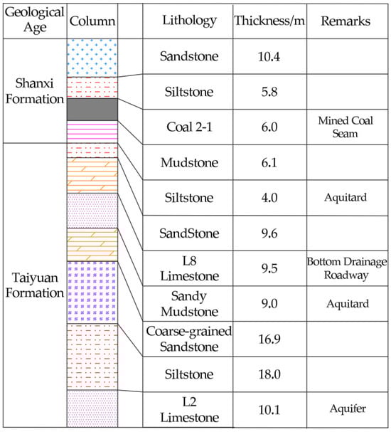
Figure 16.
Lithological profile of the surrounding rock strata in the 3903 East Transportation Bottom Drainage Roadway.
- (1)
- A circular cross-section was adopted with an excavation diameter of 5.03 m and an excavation area of 19.87 m2. This cross-section shape facilitates uniform stress distribution and mobilizes the self-supporting capacity of the surrounding rock.
- (2)
- A total of eight high-strength damping bolts of φ22 × 2000 mm were installed across the entire cross-section. The bolt diameter (22 mm), rib pattern, and height were custom-manufactured based on the numerical optimization results. The bolt spacing and row spacing were set at 1000 × 1500 mm, with an anchorage length of 1000 mm. During installation, a torque of not less than 300 N·m was applied to ensure effective pre-tensioning, and the anchorage capacity was designed to be no less than 100 kN.
- (3)
- Metal mesh made of φ6 mm welded steel bars was used, with mesh dimensions of 2000 × 1000 mm and a grid size of 100 × 100 mm. Adjacent mesh sheets overlapped by 100 mm and were securely bound together with 16# iron wires in a triangular pattern, forming an effective surface layer to prevent loose rock fall.
The specific layout of the roadway support is shown in Figure 17. A field photograph of the completed support installation is presented in Figure 18. To scientifically evaluate the support performance, systematic monitoring of roof subsidence was carried out along the test section. Monitoring points were established every 50 m, totaling four points. The subsidence was measured using a high-precision digital leveling instrument, with an accuracy of ±0.5 mm. Readings were taken daily during the initial intensive deformation stage (the first 30 days after excavation) and then transitioned to weekly measurements once the deformation rate significantly decreased, continuing for a total monitoring period of 50 days to confirm long-term stability. The monitoring data collected over a continuous 50-day period was analyzed, and the resulting time-dependent curve of roof subsidence for the test roadway is shown in Figure 19. The results indicate that during the excavation influence period, the maximum cumulative roof subsidence was only 102.9 mm. Furthermore, the subsidence rate decayed rapidly and stabilized approximately 25 days after excavation. After the roadway stabilized, the subsidence curve flattened, with a daily deformation of less than 0.2 mm, demonstrating that the surrounding rock had entered a state of long-term stability.
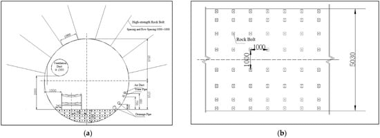
Figure 17.
Schematic diagram of the support system in the 3903 East Transportation Bottom Drainage Roadway: (a) Support Cross-section Schematic Diagram; (b) Support Plan Schematic Diagram.
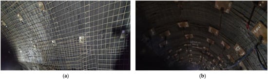
Figure 18.
Field photo of the support system in the 3903 East Transportation Bottom Drainage Roadway: (a) the sides of the roadway; (b) the roof of the roadway.
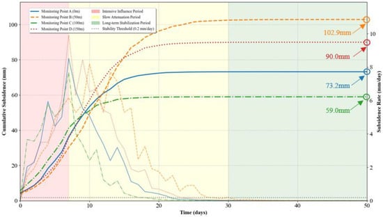
Figure 19.
Variation curve of roof subsidence over 50 days.
5. Conclusions
- (1)
- The transverse rib spacing of the bolt is a critical parameter influencing the depth and efficiency of load transfer. Increasing the rib spacing intensifies the stress concentration effect in both the bolt body and the resin ring. However, the diffusion of prestress into it is beneficial for the deeper sections of the borehole, allowing the full-length anchorage mechanism to function more effectively. Simulation results indicate that a rib spacing of 36 mm achieves an optimal balance in the peak stress and its distribution within the bolt body and resin ring, yielding the highest pull-out efficiency. Further increasing the spacing to 48 mm provides no significant enhancement. Consequently, a rib spacing of 36 mm is determined to be the optimal value within the scope and conditions of this numerical investigation.
- (2)
- The rib height of the bolt has a mitigating effect on the interfacial stress level. Increasing the rib height disperses the interfacial stress, leading to a notable reduction in stress within both the bolt body and the resin ring. While this can alleviate stress concentration, it concurrently diminishes the ability to transfer prestress, which is disadvantageous for the overall support performance of the bolt. Considering the stress response of all components comprehensively, a rib height of 1.0 mm delivers the best overall system performance, maintaining effective load transfer while preserving an appropriate interfacial stress state.
- (3)
- Increasing the bolt diameter significantly enhances the overall load-bearing capacity of the system. A larger diameter not only directly improves the tensile strength of the bolt body but also optimizes the stress distribution within the resin ring by increasing the contact area, resulting in more uniform load transfer. However, beyond a diameter of 22 mm, the efficiency of enhancing the stress level in the resin ring reaches an inflection point and decreases markedly. Considering material utilization, construction costs, and support effectiveness comprehensively, a bolt diameter of 22 mm is determined to be the optimal and reasonable design value.
- (4)
- Bolts customized based on the simulation results demonstrated excellent performance in the field application in the 3903 East Transportation Bottom Drainage Roadway at Zhongmacun Mine. Monitoring data revealed a maximum cumulative roof subsidence of merely 102.9 mm. Furthermore, the deformation rate decayed rapidly and stabilized within 25 days, with a daily deformation of less than 0.2 mm. This indicates that the surrounding rock was effectively controlled and entered a state of long-term stability.
- (5)
- The ANSYS-based finite element model developed in this study, which incorporates cohesive zone elements and surface-to-surface contact pairs, has demonstrated a reasonable capability to reflect the actual connection conditions at the bolt–resin interface under pull-out load. The model successfully captured key mechanical behaviors, such as stress concentration at the bolt ribs and the progressive diffusion of stress along the anchorage length. However, it is acknowledged that the model represents a simplification of reality. Factors such as the potential initial imperfections in the resin annulus, the complex triaxial stress state in the surrounding rock, and material heterogeneity were not fully considered. Despite these simplifications, the strong correlation between the simulation-optimized parameters and the successful field validation results indicates that the adopted computational model possesses a high degree of reliability for the purpose of parameter optimization and mechanism analysis within the scope of this investigation.
Author Contributions
Conceptualization, M.Z. and H.T.; methodology, G.F.; software, H.T. and S.Z.; validation, S.Z., Z.K. and S.L.; data curation, H.T. and C.R.; writing—original draft preparation, M.Z. and H.T.; writing—review and editing, G.F. and S.Z. All authors have read and agreed to the published version of the manuscript.
Funding
This research was funded by the National Natural Science Foundation of China (Grant No. 52574177) and University-Industry Collaboration Project: Research and Application of Rapid TBM Excavation Technology in the Jiaozuo Mining Area (Grant No. 2025210266).
Institutional Review Board Statement
Not applicable.
Informed Consent Statement
Not applicable.
Data Availability Statement
Data are contained within the article.
Conflicts of Interest
Author Mingjian Zhang was employed by the company Jiaozuo Coal Industry Zhongmacun Mine. The remaining authors declare that the research was conducted in the absence of any commercial or financial relationships that could be construed as a potential conflict of interest.
References
- Kang, H.P. Development and prospects of support and reinforcement materials for coal mine roadways. Coal Sci. Technol. 2021, 49, 1–11. [Google Scholar]
- Lu, J.Z.; Wei, F.; Ma, P.; Yang, K.; Shi, D.Q.; Wang, B. Optimization and Application of Rock-bolting Parameters for High-stress Roadway in Ganzhuang Coal Mine. Min. Saf. Environ. Prot. 2016, 43, 49–52+56. [Google Scholar]
- Kang, H.P.; Lin, J.; Wu, Y.Z.; Cheng, P.; Meng, X.Z.; Ren, S. Mechanical performances and compatibility of rock bolt components. J. China Coal Soc. 2015, 40, 11–23. [Google Scholar]
- Kang, H.P. Sixty years development and prospects of rock bolting technology for underground coal mine roadways in China. J. China Univ. Min. Technol. 2016, 45, 1071–1081. [Google Scholar]
- Yang, X.H.; Wang, L.G.; Lu, Y.L. Research on new high strength and yield rebar grouting bolt. Coal Mine Mach. 2011, 32, 160–162. [Google Scholar]
- Chen, Y.; Li, P.F.; Chen, M.; Yang, L.; Cui, X.P.; Wang, S. Failure behaviors of anchored rock mass with various fracture inclinations in tunnels. Arab. J. Sci. Eng. 2025, 50, 12665–12687. [Google Scholar] [CrossRef]
- Cao, R.L.; Peng, L.J.; Zhao, Y.F. Control of strata deformation in subway interval tunnels crossing a high-speed rail shield tunnel at a short distance. Arab. J. Sci. Eng. 2021, 46, 5013–5022. [Google Scholar] [CrossRef]
- Chen, Y.L.; Teng, J.Y.; Sadiq, R.A.; Zhang, K. Experimental study of bolt-anchoring mechanism for bedded rock mass. Int. J. Geomech. 2020, 20, 4020019. [Google Scholar] [CrossRef]
- Kang, H.P.; Wang, J.H. Rock Bolting Theory and Complete Technology for Coal Roadways; China Coal Industry Publishing House: Beijing, China, 2017. [Google Scholar]
- Xie, H.P. Research review of the state key research development program of China: Deep rock mechanics and mining theory. J. China Coal Soc. 2019, 44, 1283–1305. [Google Scholar]
- Qian, Z.Z.; Lu, X.L.; Sheng, M.Q. Experimental investigation of the tensile capacity for anchor groups with different spacing between cast-in-place headed anchors of high strength and deep embedment. Arab. J. Sci. Eng. 2019, 44, 4745–4755. [Google Scholar] [CrossRef]
- Wu, T.; Cao, C.; Zhao, X.; Zhang, M.; Zhang, H.; Ren, T.; Ma, S.; Han, J. Laboratorial study of anchorage performance in different rib spacings of bolt. J. China Coal Soc. 2017, 42, 2545–2553. [Google Scholar]
- Zhang, Z.Q.; Liu, Y.; Teng, J.Y.; Zhang, H.; Chen, X. An investigation into bolt anchoring performance during tunnel construction in bedded rock mass. Appl. Sci. 2020, 10, 2329. [Google Scholar] [CrossRef]
- Yazici, C.; Gurbuz, M.; Orhan, S.N.; Solak, K.; Ozkal, F.M. Structural performance of different baseplate configurations in storage rack systems. Arab. J. Sci. Eng. 2025, 50, 13209–13223. [Google Scholar] [CrossRef]
- Yokota, Y.; Zhao, Z.; Shang, J.; Nie, W.; Date, K.; Iwano, K.; Okada, Y. Effect of bolt configuration on the interface behaviour between a rock bolt and bond material: A comprehensive DDA investigation. Comput. Geotech. 2019, 105, 116–128. [Google Scholar] [CrossRef]
- Saadat, M.; Taheri, A. Effect of contributing parameters on the behaviour of a bolted rock joint subjected to combined pull-and-shear loading: A DEM approach. Rock Mech. Rock Eng. 2020, 53, 383–409. [Google Scholar] [CrossRef]
- Ho, S.C.M.; Li, W.J.; Wang, B.; Song, G.B. A load measuring anchor plate for rock bolt using fiber optic sensor. Smart Mater. Struct. 2017, 26, 057003. [Google Scholar] [CrossRef]
- Yu, W.J.; Wu, G.S.; Pan, B.; Wang, C.L.; Li, K.; Liao, Z. Laboratory and field investigations of different bolting configurations for coal mine roadways in weak coal strata. Bull. Eng. Geol. Environ. 2021, 80, 8995–9013. [Google Scholar] [CrossRef]
- Nourizadeh, H.; Mirzaghorbanali, A.; McDougall, K.; Aziz, N. Exploring the axial performance of protective sheathed rock bolts through large-scale testing. Tunn. Undergr. Sp. Tech. 2025, 155, 106157. [Google Scholar] [CrossRef]
- Aziz, N.; Jalalifar, H.; Concalves, J. Bolt surface configurations and load transfer mechanism. In Proceedings of the 7th Underground Coal Operators Conference, Wollongong, Australia, 8–10 February 2006; pp. 236–244. [Google Scholar]
- Aziz, N. A new technique to determine the load transfer capacity of resin anchored bolts. In Proceedings of the 3rd Australian Coal Operators Conference, Wollongong, Australia, 29–31 January 2002; pp. 176–185. [Google Scholar]
- Aziz, N. Bolt surface profiles-an important parameter in load transfer capacity appraisal. In Proceedings of the 5th International Conference on Ground Control in Mining, Morgantown, WV, USA, 3–5 August 2004; pp. 221–230. [Google Scholar]
- Aziz, N.; Jalalifar, H.; Remennikov, A. Optimisation of the bolt profile configuration for load transfer enhancement. In Proceedings of the Coal Operators’ Conference, Wollongong, Australia, 14–15 February 2008; pp. 125–131. [Google Scholar]
- Ferrero, A.M. The shear strength of reinforced rock joints. Int. J. Rock Mech. Min. Sci. Geomech. Abstr. 1995, 32, 595–605. [Google Scholar] [CrossRef]
- Blumel, M. Performance of grouted rock bolts in squeezing rock. In Proceedings of the EUROCK’96 Symposium, Turin, Italy, 2–5 September 1996; pp. 885–891. [Google Scholar]
- Lin, J.; Ren, S.; Yang, J.H. Laboratory research of resin full-length anchoring bolts dimension optimization. J. China Coal Soc. 2014, 39, 1009–1015. [Google Scholar]
- Ren, S. Study on the Contour of Left-Hand Twist Threaded Steel Bars Without Longitudal Rib for Rock-Bolts Anchored by Resin. Master’s Thesis, China Coal Research Institute, Beijing, China, 2014. [Google Scholar]
- Lin, J.; Ren, S. Numerical simulation optimization research of bolt profile configuration with resin full-length anchoring. J. Min. Saf. Eng. 2015, 32, 273–278. [Google Scholar]
- Zhao, Y.P. Study on Dimension Optimization of Grout Fully-Length Anchoring Threaded Steel Bolts. Master’s Thesis, Shandong University of Science and Technology, Qingdao, China, 2017. [Google Scholar]
- Liu, Y.X.; Xing, M.; Zhao, T.; Yu, F.; Li, L.; Chen, S.; Wang, X. Research on meso-damage experiment and simulation in the anchorage bonding interface between rock bolt and rock mass. Shock. Vib. 2024, 2024, 4189110. [Google Scholar] [CrossRef]
- Liu, Y.X.; Xing, M.L.; Liu, P.C.; Fu, Y.K. Study on fine numerical simulation of pull-out test process of anchor rock with rebar anchor. Saf. Coal Mines 2022, 53, 66–74. [Google Scholar]
- Ma, S.W.; Zhang, M.; Cao, C.; Zhang, H.D.; Ren, T.; Han, J. Numerical simulation study on rib spacing anchorage optimization of right-handed rebar bolts. Coal Sci. Technol. 2019, 47, 117–125. [Google Scholar]
- Wu, T. Study on the Relationship Between Rib Spacing and Anchorage Effect of Bolts. Master’s Thesis, Liaoning Technical University, Fuxin, China, 2017. [Google Scholar]
- Amnieh, H.B.; Bagheri, M.; Jalalifar, H. Bolt profile geometry effect on load-bearing characteristics of fully grouted rock bolts. J. Min. Sci. 2023, 59, 199–210. [Google Scholar] [CrossRef]
Disclaimer/Publisher’s Note: The statements, opinions and data contained in all publications are solely those of the individual author(s) and contributor(s) and not of MDPI and/or the editor(s). MDPI and/or the editor(s) disclaim responsibility for any injury to people or property resulting from any ideas, methods, instructions or products referred to in the content. |
© 2025 by the authors. Licensee MDPI, Basel, Switzerland. This article is an open access article distributed under the terms and conditions of the Creative Commons Attribution (CC BY) license (https://creativecommons.org/licenses/by/4.0/).