Review

Unmanned Aerial Underwater Vehicles: Research Progress and Prospects

1
School of Oceanography, Shanghai Jiao Tong University, Shanghai 200240, China
2
School of Ordnance Engineering, Naval University of Engineering, Wuhan 430033, China
3
National Key Laboratory of Science and Technology on Underwater Acoustic Antagonizing, Shanghai 201108, China
*
Author to whom correspondence should be addressed.
Appl. Sci. 2025, 15(22), 11868; https://doi.org/10.3390/app152211868
Submission received: 24 September 2025 / Revised: 30 October 2025 / Accepted: 5 November 2025 / Published: 7 November 2025
(This article belongs to the Special Issue Advances in Autonomous Underwater Vehicle Technology)

Featured Application

UAUVs are rapidly evolving, with numerous prototypes currently undergoing various stages of development. However, a significant portion of these prototypes remains in a nascent stage and exhibits limitations in functionality. The previous linear technology-push development mode resulted in application development falling far behind technology. Transforming this into a market-pull and technology-push interactive mode is a better choice in the future.

Abstract

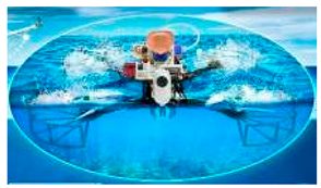
Unmanned aerial underwater vehicles (UAUVs) will play significant roles in several complex application scenarios including observation of mesoscale ocean phenomena, monitoring of offshore platforms, ocean protection, and maritime rescue. These innovative vehicles can be used in the air and underwater and can easily enter and exit water. This review systematically analyzes the research progress, design challenges, and future prospects of UAUVs, emphasizing their potential to revolutionize integrated cross-domain collaboration. We classify UAUVs into five categories—rotary-wing, fixed-wing, folding-wing, hybrid-wing, and flapping-wing—based on propulsion configurations, and critically evaluate their prototypes, highlighting technological milestones and functional limitations. Unlike prior reviews focused solely on technical developments, this study advocates for a paradigm shift from a technology-push to a market-pull and technology-push interactive development model. Combining the design of UAUV with solutions to technical challenges and specific application requirements is crucial for practical deployment. By synthesizing historical context, current advancements, and future developments, this review not only provides possible strategies for design challenges but also lays a roadmap for UAUV commercialization.

1. Introduction

Unmanned aerial underwater vehicles (UAUVs) have garnered increasing attention because they can be used in the air and underwater and can easily enter and exit water. At present, to meet the integrated detection requirements across air, surface, and underwater domains [1,2,3], a new generation of integrated air–sea detection systems has emerged. These systems incorporate buoys, fixed observation stations, marine drones, unmanned surface vehicles, underwater vehicles, satellites, and other components [4,5]. The advent of UAUVs holds promise to complement, enhance, or even replace such integrated systems at lower costs and through a more unified platform.
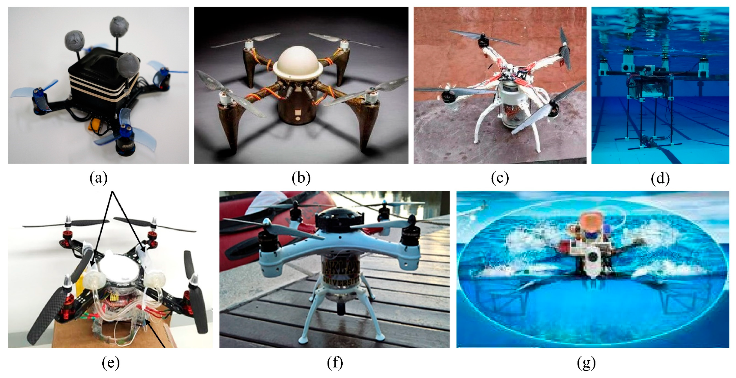
Diving planes could make multiple active water entries and exits, and they were developed in the last century. In 1934, the Soviet first began developing the “LPL” project (Figure 1a) [6,7] and an American engineer applied for a patent for a flying submersible aircraft in 1945 (Figure 1b) [8]. However, design prototypes of these vehicles were not produced. In 1964, Donald Reid, an engineer at the North American Aviation, designed and built the first diving plane prototype (Figure 1c,d) [9,10]. It could fly at an altitude of approximately 23 m above the water surface and navigate at a depth of 3 m underwater. The United States proposed several designs for large diving planes later (Figure 1e); however, they did not progress from the initial design phase due to inadequate technical expertise and nascent development stages [11,12].
Varying air and water densities are critical challenges with the mentioned vehicle, which are mitigated by UAUVs. After the failure of the demand-driven diving plane, the technology-driven UAUV has developed quickly over the past 10 years. Using databases such as Web of Science and Scopus as a benchmark, the number of articles published on UAUV has exceeded 10 annually since 2013, and this number has reached 60 in 2023.
In previous reviews, some prototypes and related technologies were introduced, although the names used for UAUV were different. Yang et al. introduced the principles of biological inspiration and bionic design [13]. Zufferey et al. focused on introducing the design process of several prototypes [14]. Zeng et al. focused on the transition control of UAUVs [15]. Yao et al. provided a good classification and some novel techniques were summarized and prospected including morphing blade and surface dehydration [16].
Both reviews from Zeng et al. and Yao et al. are informative, and they tell us what stage UAUV has reached, but we have no idea how to move UAUV forward to practicality. UAUV is a typical technology-push vehicle, and the market is a passive receiver (Figure 2). This development mode makes it not difficult to build a UAUV with basic functions nowadays, but what is still challenging is to build high-performance and practical prototypes for specific applications. This mode cannot bring sufficient funds and vitality in the short term, and its promotion effect on the applied research of the new vehicle is limited. Early electric cars, logistics drones, and wearable health devices (e.g., smartwatches and bands) also faced such a plight. Driven by technology, their initial products emerged early, but there were also a large number of mature alternatives, such as fossil-fuel cars, air and rail transport, and sphygmomanometers. Subsequently, these products found their unique entry points and specific application scenarios, entering the market-pull and technology-push interactive mode. Electric cars targeted low-cost urban commuting, with reliability and range improving rapidly. Logistics drones focused on enhancing the cost-effectiveness of air transport and solving the last-mile delivery problem. Wearable health devices seized the application scenarios of sports tracking and real-time health monitoring, and rapidly achieved technological iteration and progress. Transforming into a market-pull and technology-push interactive mode also a better choice for UAUV (Figure 2). Our review is under this thinking.
A practical prototype should have a suitable technical route, which includes the selections and optimizations of basic configuration, transition mode, and propulsion system. Furthermore, some technical difficulties also constrain the performance of the current prototypes, which include hydrodynamic calculation, buffered design, etc. The design approach proposed based on application requirements was relatively ambiguous and some technical difficulties in design were encountered, so our review offers the following improvements (Figure 2):
  • A more reasonable classification based on propulsion configuration, along with a comprehensive summary of existing prototypes.
  • Guidance for UAUV design focusing on application requirements, covering basic structure, water entry and exit, power, and control systems besides addressing technical challenges such as hydrodynamic calculations, hybrid power systems, and underwater optimization.
  • Detailed description of more applications, with specific development prospects for different UAUV configurations.
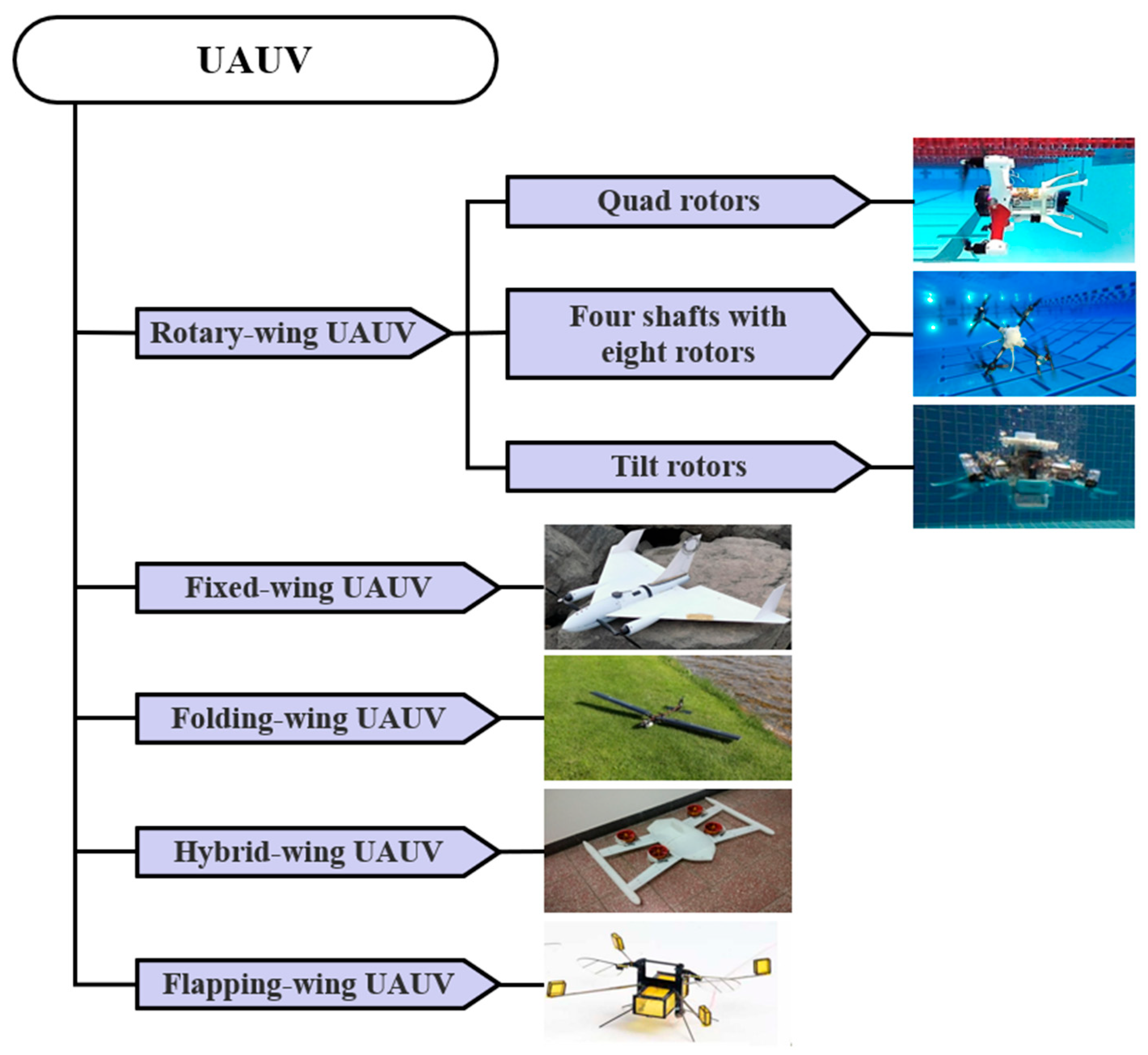
The remainder of this paper is organized as follows: A new classification system for rotary-wing, fixed-wing, folding-wing, hybrid-wing, and flapping-wing UAUVs (Figure 3) is proposed in Section 2 to facilitate better UAUV development, and current UAUVs are briefly described. Section 3 discusses the guidelines for four design foci and the related technical difficulties along with possible solutions. In Section 4, the application prospect of UAUVs for civilian use is discussed along with future research directions. Section 5 concludes the paper.

2. Research Progress

Unmanned aerial vehicle (UAV) technologies have made remarkable advancements in the 21st century. Multi-rotor, hybrid-wing, and fixed-wing UAVs have become mature and sophisticated in terms of flight and control [17,18,19]. UAVs of various sizes and functionalities are widely used in fields including surveying, mapping, plant protection, remote sensing, and aerial photography [20,21,22,23,24,25,26,27,28,29,30,31]. Autonomous underwater vehicle (AUV) technologies have also matured [32,33]. These have laid a solid technological foundation for the rapid development of UAUV. Herein, UAUVs are classified into five categories based on their propulsion configurations: rotary-wing, fixed-wing, folding-wing, hybrid-wing, and flapping-wing UAUVs. These vehicles have been primarily developed by universities and research institutes rather than companies. Table 1 lists the main parameters of these UAUVs and the experiments to clearly show the stages of development. The “Y” indicates that the corresponding experiment has been conducted, while the “N” indicates not.

2.1. Rotary-Wing UAUVs

Rotary-wing UAVs are small vehicles with a well-established structure design, manufacturing process, and control algorithm that enables vertical takeoff and landing and hovering at a fixed height. This similar technology has been widely studied and used to design and manufacture UAUVs to considerably reduce the difficulties in flight control and experiments, simplify water entry and exit processes, and enhance reliability.
On the basis of a small quad-rotor UAV, a basic quad-rotor UAUV can be manufactured by simply sealing the battery cabin and electronic equipment cabin, adding a brushless motor with general waterproof performance, and finally adjusting the relationship between gravity and buoyancy using buoyancy materials or counterweights. The rotary-wing UAUV prototypes is the most common in the five categories due to the mature technology.

2.1.1. Quad Rotors

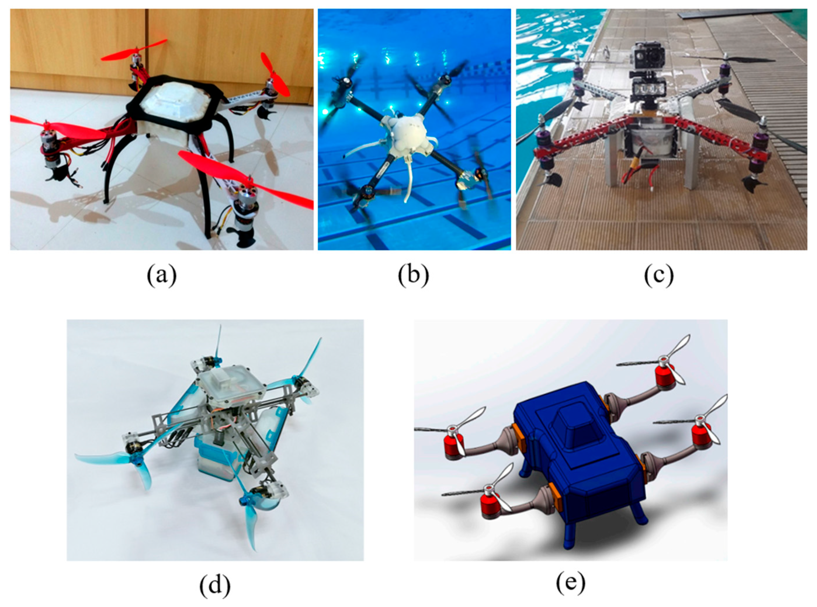
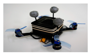
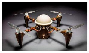
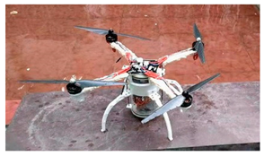
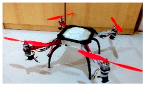
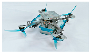
The same propellers were used for both air and underwater propulsion. In 2019, researchers from the University of California, Berkeley, developed a micro quad-rotor UAUV (Figure 4a) weighing only 0.2 kg and successfully conducted a water exit test [34]. In 2016, researchers from Johns Hopkins University Applied Physics Laboratory created a quad-rotor UAUV with a focus on anti-corrosion design (Figure 4b). Its lightweight, corrosion-resistant composite material body and anti-corrosion coating on the exposed components such as motors allowed the prototype to remain underwater for two months without corrosion [35]. In 2021, researchers from Shanghai Maritime University developed a quad-rotor UAUV prototype (Figure 4c) by focusing on the control system; theoretical and experimental analysis demonstrated the superior robustness of fuzzy proportional–integral–derivative (PID) controllers over traditional PID controllers in crossing the water–air interface [36].
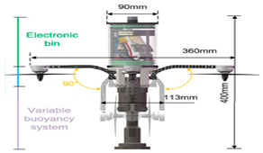
Some quad-rotor UAUVs use a buoyancy adjustment mechanism. For example, in 2016, researchers from the Georgia Institute of Technology used a quad-rotor UAUV with a buoyancy adjustment device (Figure 4d) to simulate water sample collection at a specified depth in designated waters. The quad-rotor UAUV completed the task considerably faster than traditional AUVs in the mission profile with vertical water columns rather than horizontal columns [37]. Researchers from the University of Auckland used a buoyancy regulation device to increase underwater speed and maneuverability. When the vehicle absorbed water into the ballast tank, its fuselage inclined to 90°, causing the direction of action of the quad-rotor to become horizontal. They produced two prototypes in 2015 and 2018 (Figure 4e,f) [38,68].
Folding the rotor arms underwater is a good choice as it has adverse effects on navigation. The UAUV which is designed in this way is cylindrical with large slenderness ratio to obtain folding space. In 2023, the foldable quad-rotor UAUV designed by researchers from Shanghai Jiao Tong University (SJTU) has undergone experiments [39], and researchers from Harbin Engineering University and Nanjing University have also developed similar designs in 2023 and 2024, respectively [69,70].
In addition, unique biological characteristics have been incorporated into rotary-wing UAUVs. Researchers from BeiHang University (BUAA) were inspired by remoras, a type of fish with a flat head and oval-shaped disc, which allow them to attach to large fish or boats and travel to food-rich areas. They developed a UAUV (Figure 4g) imitating the suction cup structure of remoras, which can “hitchhike” and reduce energy consumption, as observed in remoras attached to dolphins even when they jump out of the water [40,71]. This approach provides a novel idea for the energy-saving design of UAUVs.
Figure 4. Quad rotors: (a) The University of California, Berkeley micro quad-rotor UAUV in 2019 [72]; (b) Johns Hopkins University Applied Physics Laboratory quad-rotor UAUV in 2016 [73]; (c) Shanghai Maritime University quad-rotor UAUV in 2021 [72]; (d) Georgia Institute of Technology quad-rotor UAUV in 2016 [72]; (e) The University of Auckland quad-rotor UAUV in 2015 [72]; (f) The University of Auckland quad-rotor UAUV in 2018 [73]; (g) BUAA bionic UAUV that imitated remora in 2022 [40].
Applsci 15 11868 g004

2.1.2. Four Shafts with Eight Rotors

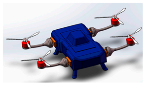
In a rotary-wing UAUV, using different propellers for air and water propulsion is the most suitable propulsion mode. Researchers from Universidade Federal do Rio Grande (FURG) in Brazil first developed rotary-wing UAUVs. In 2014, they designed a four-shaft-eight-propeller UAUV and proposed a detailed structural design and motion control model [74]. The UAUV was equipped with four four-bladed water propellers with a diameter of 15 cm under four two-bladed air propellers with a diameter of 60 cm to ensure efficient propulsion in both media. Although no prototype was built, that study provided a direction for the development of rotary-wing UAUVs. Subsequently, in 2018, they manufactured a UAUV prototype based on their previous design (Figure 5a) [41] and made specific optimizations for its underwater and aerial propellers [75].
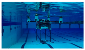
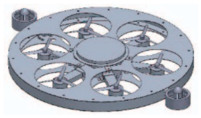
In 2017, researchers from Rutgers, the State University of New Jersey, designed and manufactured a four-shaft-eight-propeller UAUV prototype (Figure 5b), which underwent a series of successful pool tests [42,76]. They also optimized its basic structure, endurance, and other performance [77]. Researchers from Air Force Engineering University and Zhejiang University have also conducted their designs in 2018 and 2022 based on similar configuration (Figure 5c) [43,78].

2.1.3. Tilt Rotors

Several UAUVs use tilt rotors to rotate the propeller direction via mechanical devices. For example, a tilt-rotor UAUV (Figure 5d) was developed by the National University of Singapore in 2020 [44]. During air flight and when crossing the water–air interface, it operates similarly to quad-rotors. However, its tilt structure enables it to change the direction of the propeller and function as a vector propulsion system underwater, thereby enhancing the underwater speed and maneuverability. Moreover, the prototype was subjected to pool tests. Researchers from Dalian Maritime University and Moscow State Technical University have also developed the design of a tilt-rotor UAUV (Figure 5e) [45,46]; however, they did not manufacture its prototype.
The complex mechanical structure limits suitability of tilt rotors as a straightforward and reliable UAUV, making it less practical.

2.2. Fixed-Wing UAUVs

The power of rotary-wing UAUVs needs to overcome gravity, rather than smaller resistance. The load and endurance of rotary-wing UAUVs are considerably restricted, and this is an inherent drawback of the rotary-wing configuration for not only UAUVs but also UAVs. Fixed-wing UAUVs are good means to solve this problem. Nevertheless, they encounter novel challenges related to water entry and exit modes, design compatibility, and shape and structure optimization in different fluids.
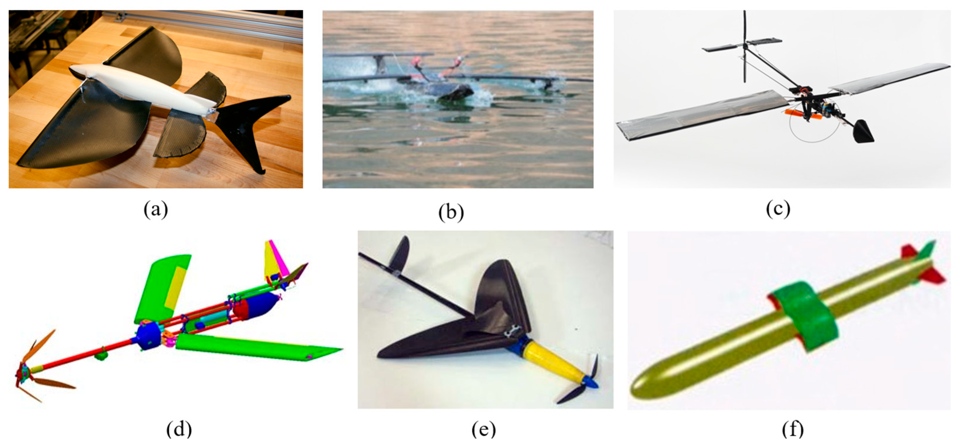
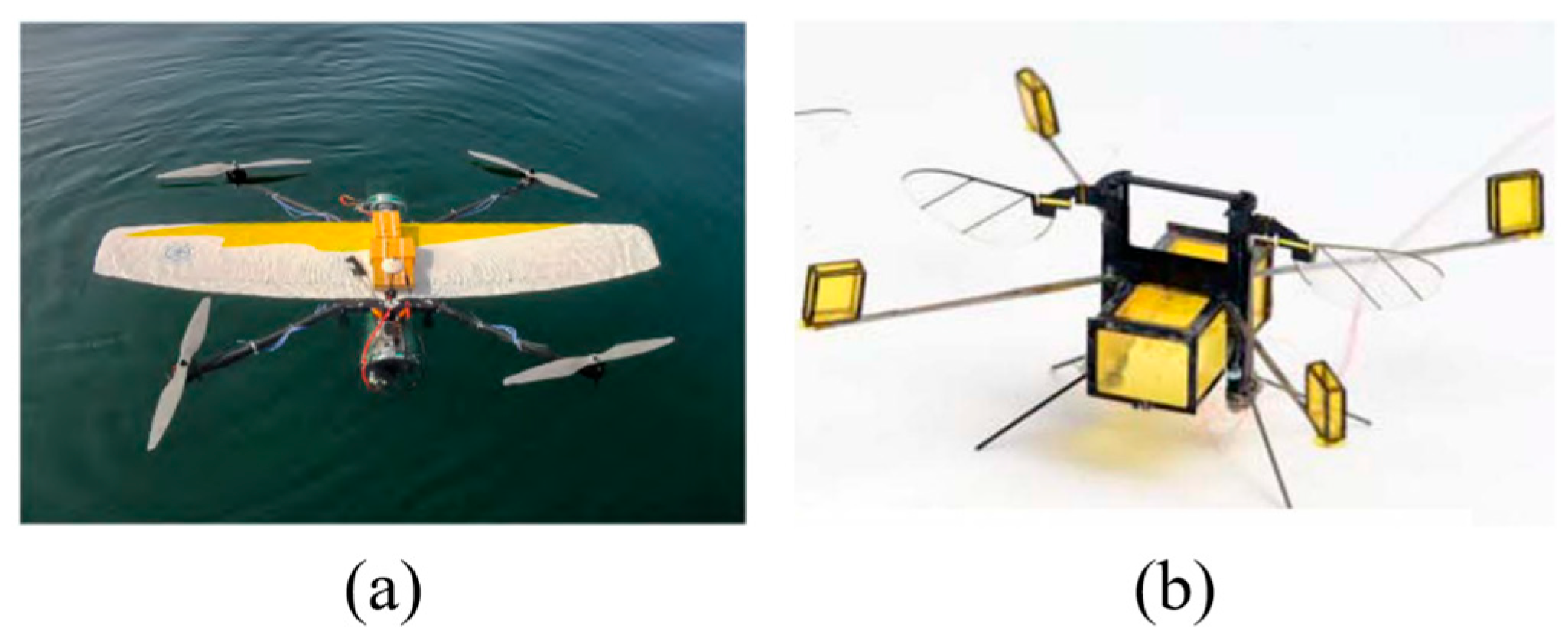
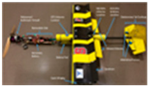
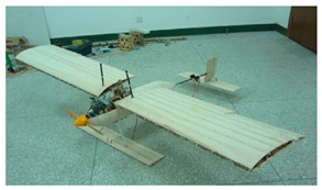
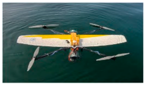
In 2017, researchers from North Carolina State University conducted experiments with a fixed-wing UAUV that used water-absorbing wings (Figure 6a). This prototype adjusted its center of gravity through the buoyancy regulation system when preparing to exit the water. This adjustment allowed the fuselage to attain a nearly vertical attitude on the water surface. It also enabled the prototype to be pulled out of the water by a tractor propeller. Notably, the prototype underwent a full-mission test, including underwater cruising, water exit, air flight, water entry, and underwater cruising. The airspeed, maximum range, and underwater speed were 22 m/s, 8470 m, and 0.68 m/s, respectively, during the test [47]. They also investigated several subsystems, such as dynamic modeling of the drainage process [79], buoyancy regulation system [80], submerged wings [81], and air and underwater propulsion systems [82].
Similarly, researchers from the University of Sherbrooke designed a more innovative fixed-wing UAUV (Figure 6) [48] in 2017, which featured a movable tractor propeller. When the UAUV was ready for take-off from the water surface, the propeller rotated 90°, perpendicular to the water surface and fuselage, allowing it to take off vertically. As the head of the UAUV was lifted to a certain distance, the propeller gradually rotated to the level of the fuselage and was fixed. The conventional take-off approach used by fixed-wing UAUVs requires underwater acceleration before rushing out of the water has created challenges in designing the propulsion device and control system. The fixed-wing designed at the North Carolina State University and the University of Sherbrooke mitigated the aforementioned problems, similar to the hybrid-wing UAUVs.
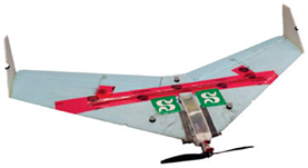
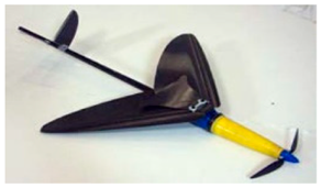
In 2018, researchers from Johns Hopkins University designed a fixed-delta-wing UAUV (Figure 6b) that used a single propeller for optimal air flight and underwater cruising [49]. This design allowed the UAUV to emerge directly from the water in the submersible mode and convert to the flight mode.
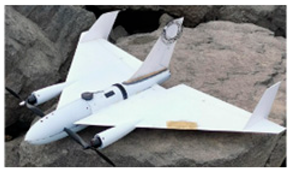
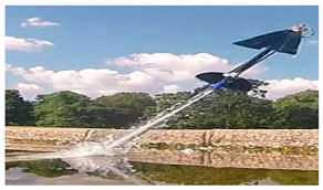
In 2019, researchers from Imperial College London completed a jet-propulsion-water-exit experiment on a fixed-wing UAUV (Figure 6c) that employed a newly developed combustion device to ignite acetylene and produce a highly exothermic reaction for water jet propulsion. Notably, the fuel consumption of this combustion device was low, enabling the vehicle to complete multiple water exits in one task [50].
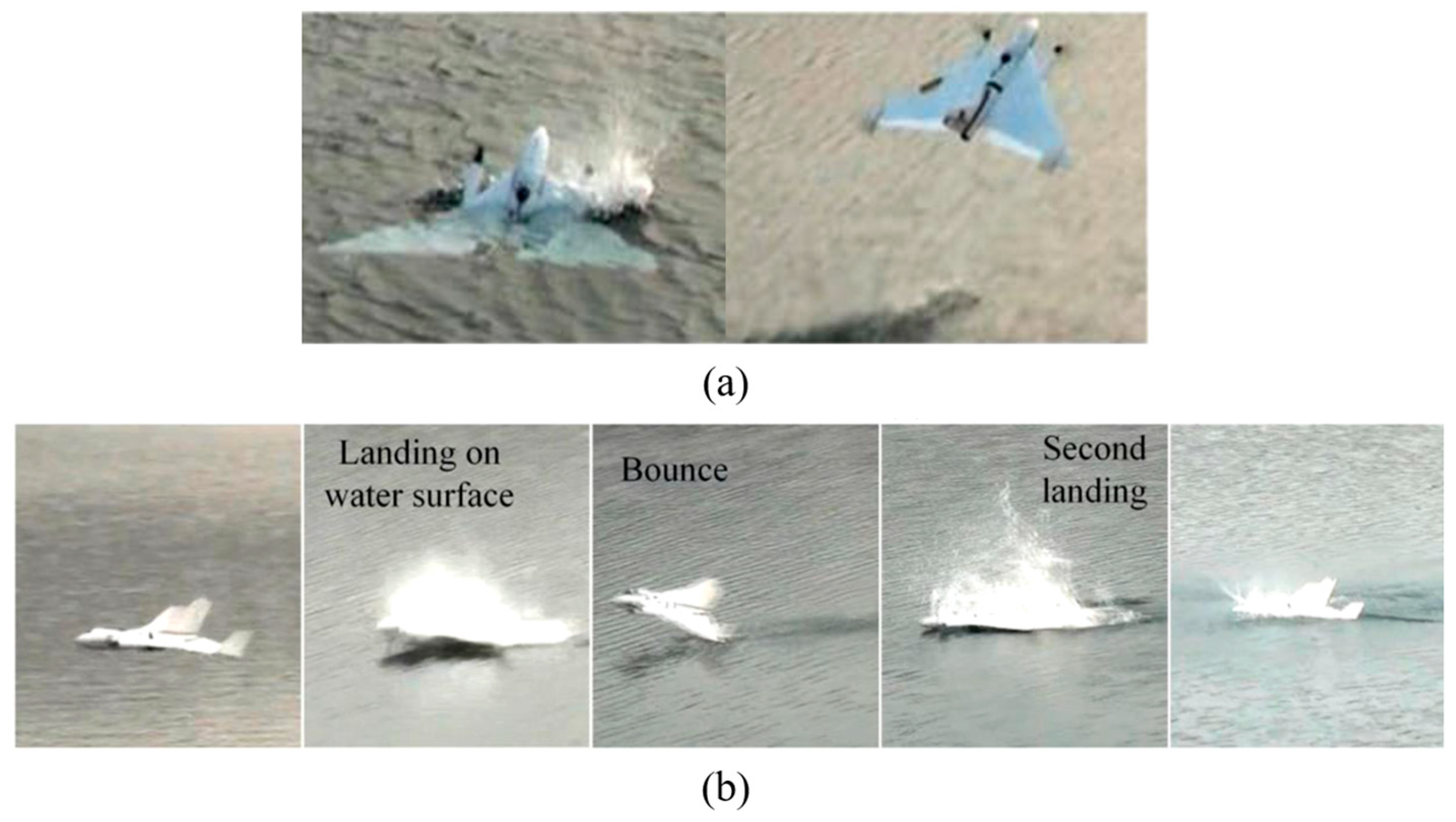
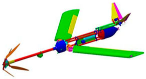
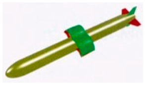
In 2022, researchers from SJTU designed a fixed-delta-wing UAUV called the “diving beetle–Δ” with a set of tractor-counter-rotating propellers (Figure 6d) [51]. The propeller slipstream generated during the water exit produced high lift. This high lift enabled a fast water-air transition, with a maximum inclination of 30°. The transition was driven by net buoyancy, propeller power, and inertia. During the test, the prototype entered and exited the water multiple times, and its maximum flight speed in the air and operating water depth reached 41.7 m/s and 50 m, respectively, demonstrating its practicality. This design is suitable for scenarios requiring rapid underwater detection. After a periodic high-speed flight in the airspace, it could dive directly into the target water area. After rapid detection or sampling in the water, it can quickly exit the water to reach the next target water area.
In 2022, researchers from Khalifa University of Science and Technology created a bold design for the fixed wing that allows it to rotate along the wing span, changing the direction of the propellers to aid in takeoff and landing [83].

2.3. Folding-Wing UAUVs

Fixed wings with large areas and the ability to generate significant lift have an adverse effect on the diving and underwater maneuverability. It will also generate larger wing loads when entering the water, requiring high requirements for wing strength design. The implementation of folding wings is a viable solution to reduce underwater navigation resistance and impact force, and enhance underwater maneuverability. In flight, the UAUV extends its wings, similar to that of a fixed-wing plane; the wings retract underwater, similar to an AUV. Notably, these designs are often inspired by natural organisms and their entry and exit modes, such as boobies, gannets, and kingfishers that can quickly dive into the water to catch prey and flying fish that can rush out of the water and glide through the air to evade predators. Folding wing designs have only been implemented in many small UAUVs, and most current prototypes have very limited functionality.
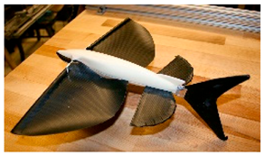
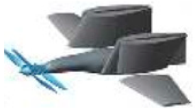
The first folding-wing UAUV modeled after flying fish was designed by researchers from Massachusetts Institute of Technology (MIT) in 2012 (Figure 7a) [52]. The folding-wing UAUV with bionic fins was designed by the U.S. Research Laboratory in 2016 [53]. The folding-wing UAUVs based on the shape of the kingfisher was designed by Jilin University and Center South University in 2019 and 2020 [54,55]. These researchers focused on studying the aerodynamic or hydrodynamic performance of the unfolded or folded state, with limited experimental research on autonomous flight or navigation of the prototype.
In 2012 and 2014, researchers from Nanchang Hangkong University and BUAA designed two similar folding-wing UAUVs, respectively (Figure 7b) [56,57]. When exiting the water, they must first float on the surface before taxiing off. When entering the water, they must first land on the water surface and then dive underwater. However, the former could only glide on the water surface at high speeds instead of taking off, possibly due to the small thrust-to-weight ratio. The latter adopted variable density fuselage and was used in water entry and exit experiments. Thus, UAUV completed a single transition in more than 15 min.
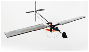
Unlike these aforementioned designs, some folding-wing UAUVs dive into the water; thus, studies focused on the process of entering the water. In 2012, the prototype from MIT could dive into the water at a speed of over 7 m/s. It was the first UAUV equipped with a practical folding wing mechanism and hydrophobic coating (Figure 7c) [58]. Since 2013, researchers from BUAA have conducted a series of studies on a folding-wing UAUV (Figure 7d). When the UAUV was sailing underwater, it used a tail propeller. When the UAUV was prepared to exit the water, its head airbag inflated. The inflation made the UAUV vertical. Meanwhile, the UAUV used a tractor propeller during the water exit process [59]. Vertical water entry calculations using computational fluid dynamics (CFD) [84], prototype tests [85], and special device tests [86] were performed to evaluate the effects of water entry velocity, inclination, wing sweep angle, and other factors on the fuselage structure, fuselage stability, and wing load. These studies provided valuable reference data for the design of this type of UAUV, particularly for the wing structure and water entry mode. In 2017, researchers from Imperial College London designed a miniature UAUV (Figure 7e) with only 201 g modeled after the gannet. They used wind and water tunnels to test the air flight and underwater cruising performance of the UAUV. Based on the findings, they used ballistic models to analyze the impact of airspeed and height on the water-entry attitude [60].
In 2017, they also developed a folding-wing UAUV that used a high-pressure CO2 gas tank to achieve water jet propulsion and reach a speed of 11 m/s [61]. Compared to the frequency of the fixed-wing UAUV developed by Imperial College London, that of this compressed-gas jet propulsion is considerably lower than the chemical reaction-driven jet propulsion.
In 2021, researchers from the Swiss Federal Institute of Technology Zurich completed the full test of a folding-wing UAUV, including underwater cruising, water exit, air flight, water entry, and underwater cruising, making it the first folding-wing UAUV to undergo a complete workflow test [62]. The newly designed clutch could use one motor to drive the aerial and underwater propellers, thereby reducing the weight of the body. The prototype weighed 3.1 kg, with a maximum flight speed of 30.6 m/s in the air and a maximum underwater diving speed of 3 m/s. Although the prototype briefly fluctuated in height after the nose broke out of the water, it could still complete the water–air transition quickly at 80°.
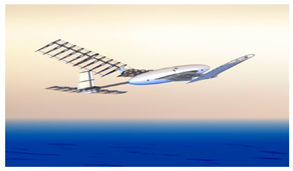
When the UAUV speed increases to transonic or higher, technical difficulties become more formidable as speed increases. The relevant theoretical calculation methods, shape and structure design, and power/propulsion system design differ drastically from low-speed UAUVs. Since 2012, researchers from Air Force Engineering University have conducted initial studies on the folding-wing shape, structure, and aerodynamic performance of such high-speed UAUVs (Figure 7f) [63,87].

2.4. Hybrid-Wing UAUVs

By ameliorating the limitations of fixed-wing and rotary-wing UAUVs and combining their strengths, we can design a UAUV that is dependable, simple, and can carry substantial payloads for prolonged periods. Hybrid-wing UAUVs possess these advantages but only a few researchers from SJTU and the Shenyang Institute of Automation, Chinese Academy of Sciences, are currently exploring this field.
In 2017, researchers from the Shenyang Institute of Automation, completed the testing of the first hybrid-wing UAUV, named “Hai Kun” [64]. This UAUV used low-aspect-ratio wings and a blended wing body. These components provided lift for the UAUV during air flight. Additionally, it was equipped with four tilt-duct propellers, which enabled vertical takeoff and landing on water. The propellers could also generate the thrust required for air flight and underwater cruising by adjusting their angle. However, the prototype only underwent basic testing, such as air flight, underwater cruising, and water-surface takeoff.
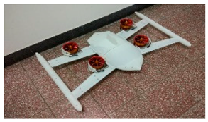
In 2022, researchers from SJTU completed the testing of the “Ne Zha” hybrid-wing UAV (Figure 8a) [65], which was equipped with four propellers for vertical lift, a tractor propeller for tension, and a pair of wings. Similarly to “Hai Kun”, “Ne Zha” could also take off and land vertically on the water surface, but its main focus was on underwater cruising performance. Its wings and tractor propeller enabled it to perform zigzag motions underwater, similar to a hybrid underwater glider. Although the quad rotors provided a lift in the air, the optimized wing design primarily targeted underwater performance, resulting in poor horizontal flight performance, limited flight speed, and endurance. Consequently, this UAUV was more akin to a rotary-wing UAUV for its operating mode in the air.

2.5. Flapping-Wing UAUV

The principle of generating lift and thrust in the air varies depending on the frequency of flapping wings. At present, the mechanism of some high-frequency flapping phenomena has not been theoretically explained. Flapping wings pose new difficulties to the design of UAUVs, particularly during water entry and exit. To address this issue, some prototypes was introduced.
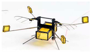
Researchers from Harvard University initiated the development of a micro flapping-wing aircraft in 2013, addressing fundamental issues in structural and motion control [88]. By 2015, they had developed the first flapping-wing UAUV following further improvements, with its aerial flight and underwater cruising performance verified through CFD calculations and prototype testing, respectively. The prototype, which weighed only 80 mg, could not overcome surface tension easily when using flapping wings to rush out of the water surface [89]. In 2017, the researchers equipped the prototype with a 40 mg pulse device, increasing the overall weight to 175 mg (Figure 8b). When the prototype was underwater and ready to emerge, the electrolytic plate was first activated. The activated plate caused the electrolytic water to generate oxygen and hydrogen in the gas collection chamber. This gas generation increased the prototype’s buoyancy. After the prototype surfaced, it could remain stably afloat due to surface tension. Finally, a successful takeoff was achieved by igniting hydrogen and oxygen with an electric spark, and this mode of takeoff was repeatable [66].
In 2015, MIT researchers conducted calculations and tests on a larger flapping-wing UAUV in both air and underwater. They summarized the laws of flapping-wing propulsion in these media and provided a general formula for calculating the weight of a flapping-wing vehicle based on its speed. However, water entry and exit were not tested, highlighting the issue with flapping-wing UAUVs. This issue aggravates with increasing size and weight [67].

3. Design Focus and Technical Difficulties

After reviewing the 33 UAUVs, we observed that the carrier was not yet fully developed, even without considering its application. When designing a UAUV, various technical routes must be considered and challenges must be addressed. Herein, technologies, their research progress, and future directions are discussed. We identify design patterns and guidelines from four critical design stages of UAUVs and propose practical solutions for common technical difficulties. The four design foci are as follows:
  • Basic appearance and structure
  • Water entry and exit mode
  • Power and propulsion system
  • Control system

3.1. Basic Appearance and Structure

Design compatibility and optimization of shape and structure must be ensured in the early stages of UAUV design, as it directly affects the speed and maneuverability of the vehicle. Systematic design methods must be devised for selecting the optimal configuration, and further research must be conducted on technical difficulties such as variable density mechanism and morphing wing mechanism.

3.1.1. Configuration Selection

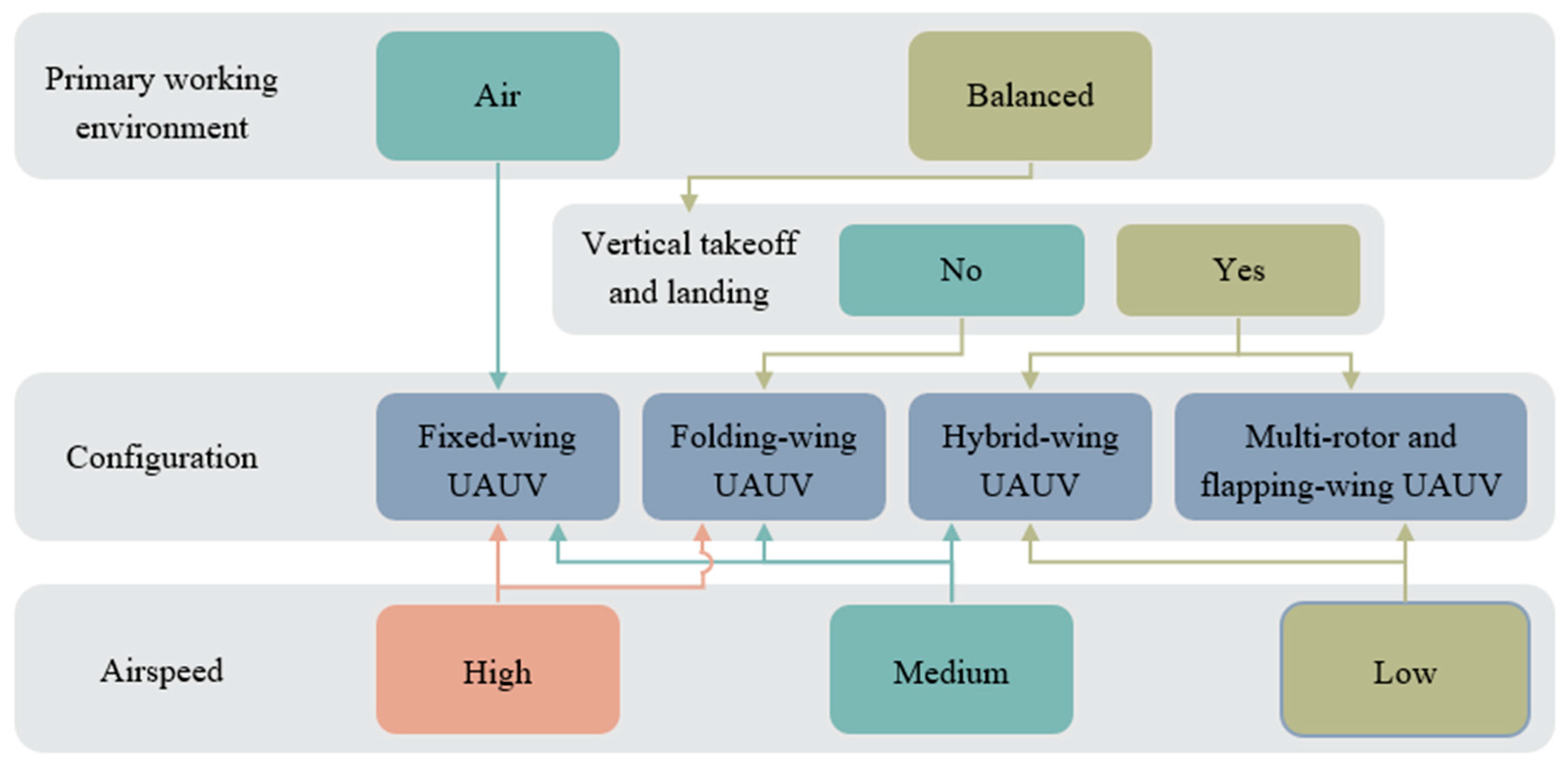
UAUV research involves many fundamental scientific issues; however, numerous existing technologies are used for their design and manufacturing. Thus, practical applications must be focused on to improve its utility. The primary working environment and airspeed are crucial for identifying the ideal UAUV configuration that fits the mission requirements.
Figure 9 shows the process of selecting the UAUV configuration based on the working environment and airspeed. When the main working environment is in the air and high speed is required, a fixed-wing UAUV is chosen. When the work environment requires balancing two different environments and vertical takeoff and landing capability is required, then hybrid-wing, rotary-wing, and flapping-wing UAUVs are suitable.
Some first person view (FPV) drones can also achieve high speeds, such as the FPV racing drones, which can reach a maximum speed of 63 m/s. However, the endurance of FPV drones is generally 3 to 8 min, and the FPV racing drones mentioned above generally have the endurance time of no more than 3 min. Ordinary small quad-roto UAVs can easily exceed the endurance of 20 min. High-speed performance at the cost of extremely low endurance is not suitable for UAUV, because the demand for water entry and exit and more complex tasks than UAVs. The folding-wing UAUV is unique because it can achieve performance similar to fixed-wing UAUV in the air, and folding the wings can enhance underwater maneuverability and speed.

3.1.2. Variable Buoyancy System

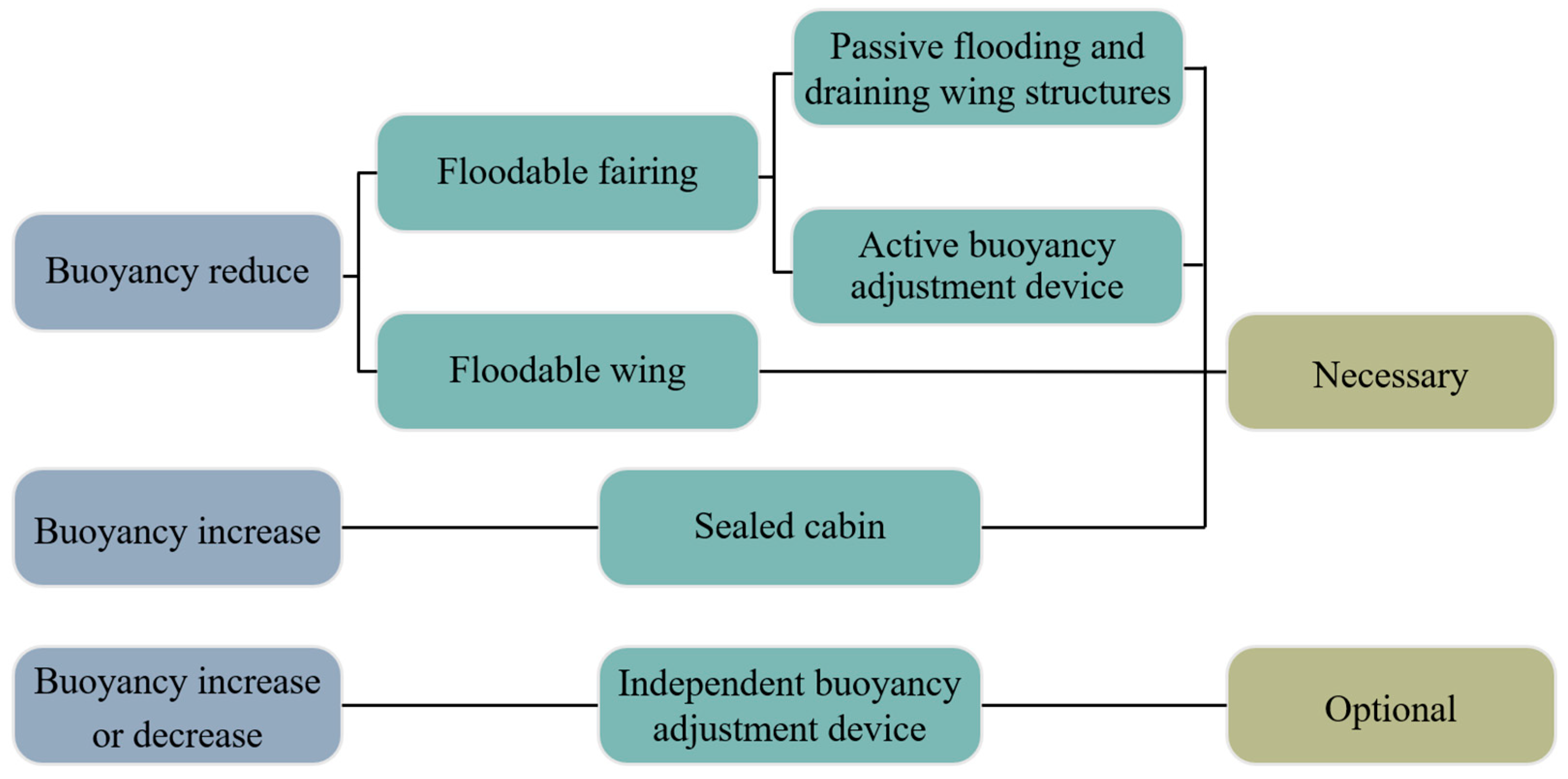
In order to help UAUV submerge underwater, gravity and buoyancy need to be close. The structures, such as the battery cabin, wings, load cabin, and fairing, cannot all be sealed. This is a problem that has not been considered in UAVs, which requires the help of variable buoyancy systems.
Figure 10 shows several methods for variable buoyancy systems. Generally speaking, the body fairing and wings of UAUV contain a large volume, so this part must be made floodable to help reduce underwater buoyancy. Sealed cabins can ensure the safety of electronic equipment underwater, but they also increase buoyancy. Ensuring neutral buoyancy underwater through the design of sealed cabins and floodable structures is a good design. If it cannot be achieved or there are other requirements to change buoyancy, an independent device for buoyancy adjustment can be used.
It is more difficult to design floodable wings than floodable fairing due to the flat shape. A floodable wing can be developed through two approaches. One is using active buoyancy adjustment devices (e.g., pumps) to flood and purge water from the wing volume [80]. The water flow rate of this pump is shown in Equation (1).
V ˙ = δ ω μ 2 π                       ( W a t e r   f l o w i n g   i n t o   t h e   t a n k ) k A 2 η ( P g P z ) ρ ( 1 k 2 )     ( W a t e r   f l o w i n g   o u t   o f   t h e   t a n k )
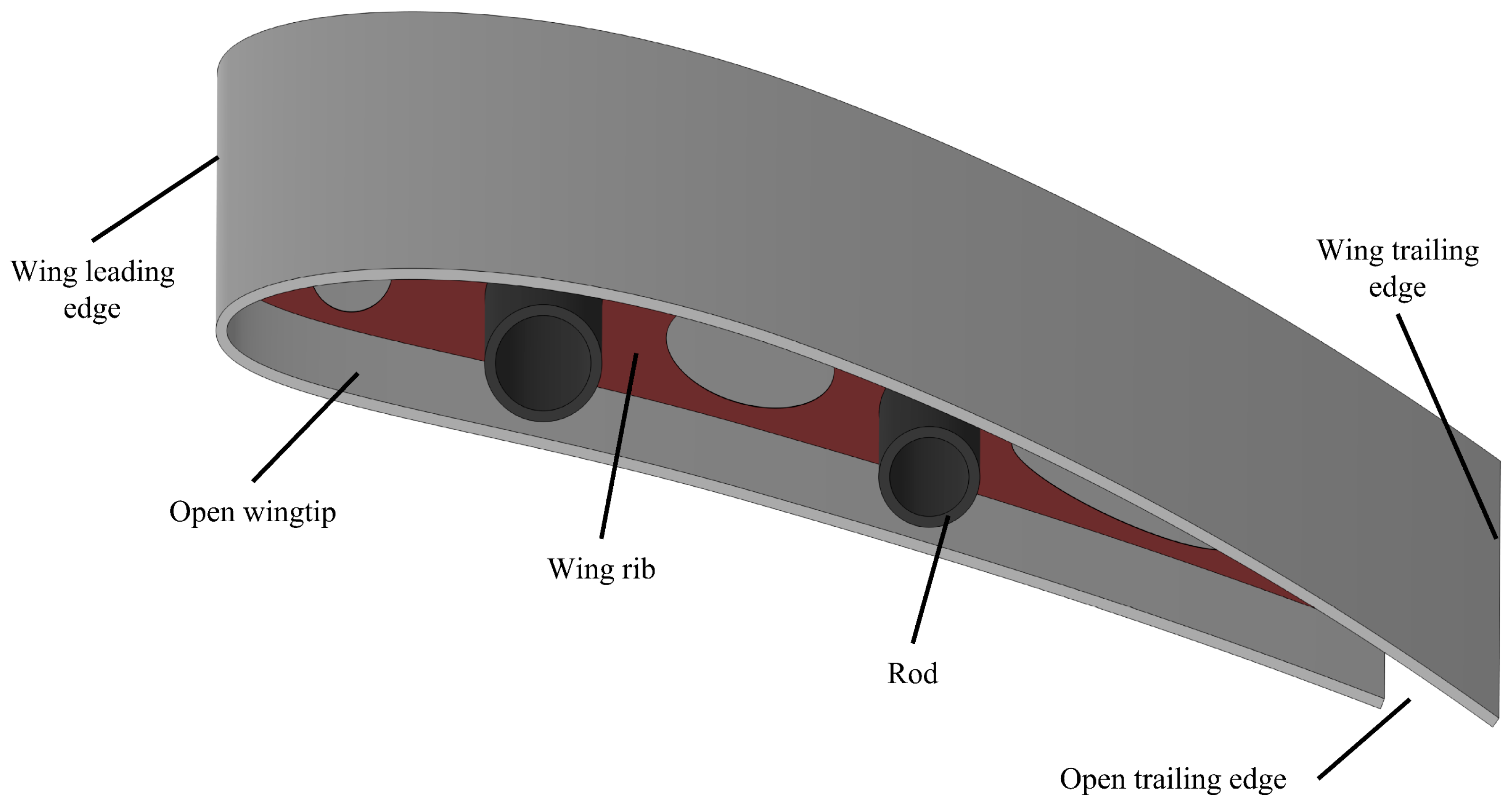
V ˙ is the volumetric flow rate of water, δ is the fixed volumetric displacement of the positive displacement pump, ω is the rotational speed of the pump shaft, μ is the volumetric efficiency of the pump, k is the nozzle area ratio, A is the cross-sectional area of the ballast tank, η is the vent valve nozzle efficiency, P g is the absolute pressure of the compressed air inside the ballast tank, P z is the ambient water pressure at the vehicle’s current depth, and ρ is the density of ambient seawater. When water flowing into the tank, the flow rate mainly depends on the rotational speed of the pump. When water flowing out of the tank, the flow rate depends on the pressure difference formed during water injection. The other approach is via passive flooding and draining wing structures, which mainly include open wingtips and open trailing edges on the wing (Figure 11).
In 2018, researchers from North Carolina State University constructed a passive floodable wing for their fixed-wing UAUV using open wingtips and open trailing edges, which only slightly increase drag when used together, with no notable effects on lift and drag acting independently [81]. In addition, the structures in the span direction inside the wings should be minimized as much as possible to reduce the obstruction of water flow in the wings.
The buoyancy adjustment device is independent for real-time fine-tuning and adjusting the buoyancy of the vehicle. This improves the stability and maneuverability of vertical navigation substantially. However, the design is complex and consumes more energy. Yao et al. divided this method into three types: variable mass, variable volume, and bionic methods [16]. The variable mass method uses a water ballast tank to change mass, and the variable volume method uses an oil sac or air sac to change volume. The folding-wing UAUVs from BUAA use these two methods separately [57,59]. The independent buoyancy adjustment device for wings is a variable mass system and can be used for water ballast tanks. The bionic method is inspired by waterfowl feathers. In 2011, Yang et al. developed a bionic density variation system that imitated the mechanism of waterfowl feathers and achieved stable flotation at a depth of 7.4 m [90], but this approach is yet to be effectively used in UAUVs.

3.1.3. Deformable Wing System

Herein, we elaborate on measures to mitigate the impact of wing lift. To address this issue, most UAUVs employ a combination of folding mechanisms and rigid wings, leading to a proliferation of folding-wing UAUVs.
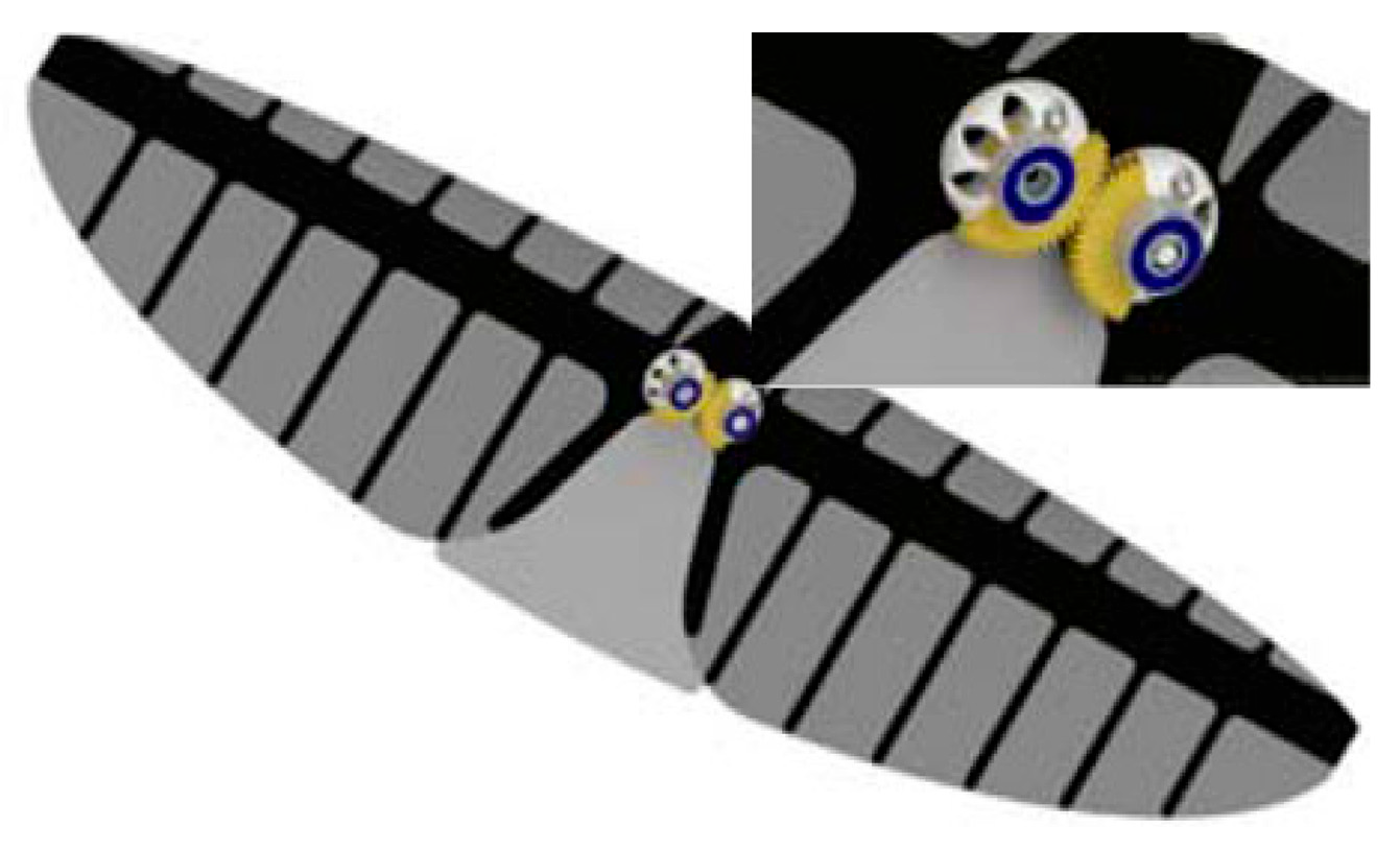
The design of folding mechanisms is diverse. Fabian et al. designed an actively triggered wing folding mechanism powered by elastic carbon fiber rods to fold the wings completely in 0.25 s [58]. Yao et al. adopted a guide screw-slider device [57]. This device was driven by a high-torque metal gear servo. The slider of the device drove the parallel motion of two linkage groups. This motion enabled the wings to stretch and fold synchronously. Yang et al. used high-pressure gas in the air tank to drive the gear cylinders [59]. Siddall et al. employed a pair of meshing gears driven by a rudder to change the swept-back angle (Figure 12) [60].
UAUVs do not require fast wing folding or unfolding speeds in general, which is unlike UAVs launched from cylinders using high-pressure gas. Therefore, it appears currently that using a gear or rod structure driven by a steering engine is simple and practical, and this can also conveniently control the wing sweep angle, improving the efficiency of aerial flight at different speeds. Further, optimizing the structure and folding process for this combination requires multi-body dynamics. Although this process is commonly used in studies related to folding wing for aircraft and missiles, it has not been explored for UAUVs.
In the future, with the development of intelligent materials and structures, folding-wing designs need not be limited to the aforementioned combination. When flexible materials are used, the deformed wing can adapt to both airborne and underwater needs. The adoption of intelligent flexible materials enables the wings to not only avoid exhibiting side effects underwater but also further enhance underwater maneuverability. Moreover, the wings can also maintain an optimum form under varying postures and speeds in the air.
Wings utilizing flexible materials are required to simultaneously possess large-scale deformation capability and aerodynamic load-bearing capacity. Corrugated composites achieve the ultra-anisotropy of “longitudinal rigidity-transverse flexibility” through corrugated geometric design. Yokozeki et al. modified corrugated composites, achieving higher longitudinal stiffness and 45% transverse elongation [91]. Polymer-based skins, including those made of corrugated composites, as well as shape memory polymer skins, are currently more suitable for deformations in the chordwise direction of the wing or at the wing tip [92,93]. To minimize the underwater impact of the wing, unmanned aerial-underwater vehicles (UAUVs) need to significantly change the wing span, and this application method still requires further exploration. The macrocomposite flexible skins developed by Bowman et al. achieved large-scale geometric changes of 40% in wing span and 70% in wing area [94]. Zhang et al. established a dynamic model for the spanwise deformation of the wing, optimizing issues such as vibration and displacement error [95]. These methods can partially achieve the effectiveness of folding wings.

3.2. Water Entry and Exit

Appropriate water entry and exit modes, as well as good design and application of related structures and materials, are vital for UAUVs. This section will focus on analyzing the advantages and disadvantages of various water entry and exit modes, identifying the selection methods, and providing potential solutions for related key technical issues such as hydrodynamic calculation, and buffered and load reduction design.

3.2.1. Water Entry and Exit Modes

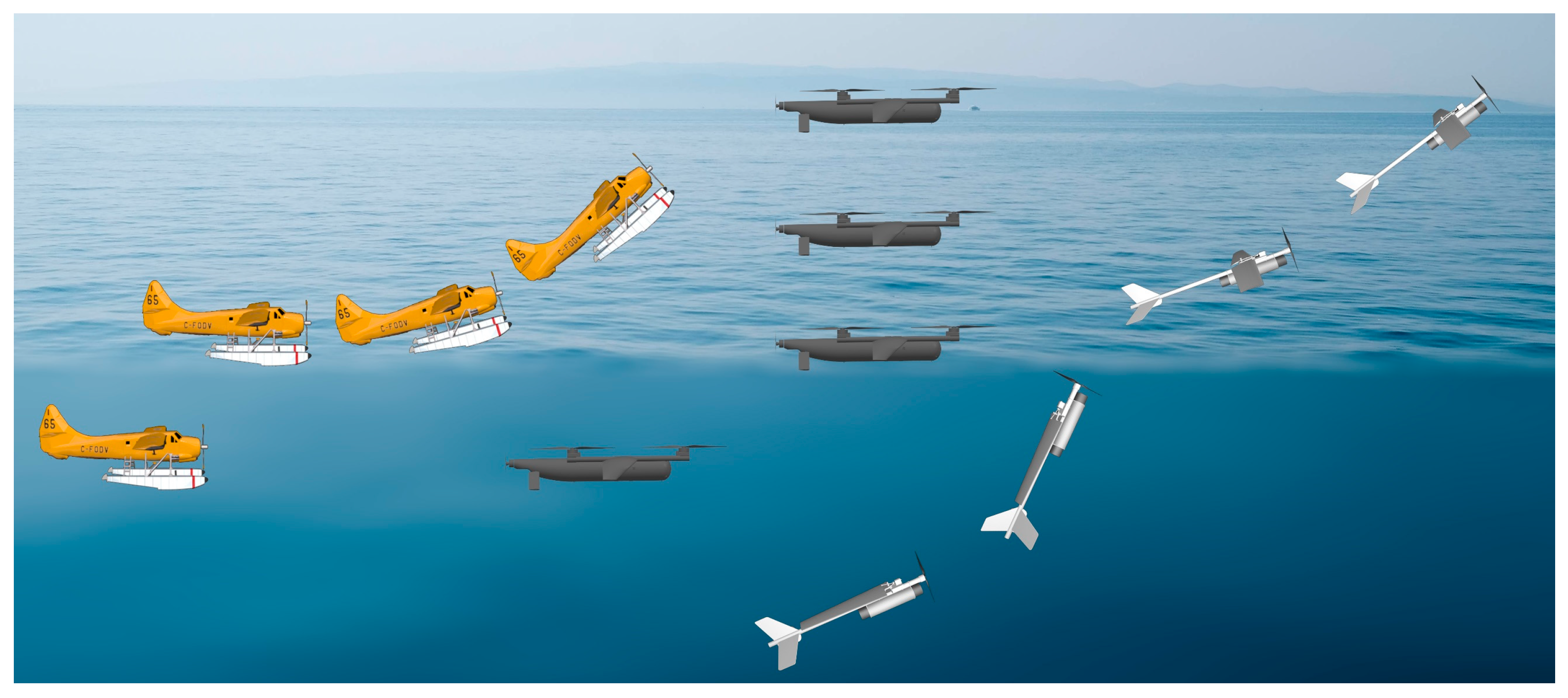
Section 3.1.1 describes the rationale and steps for selecting the ideal UAUV configuration. After selecting the basic configuration, determining the water entry and exit mode is crucial. The water-to-air transition modes are mainly classified into three types: gliding takeoff, rotor takeoff, and pull takeoff (Figure 13). The vehicle needs to rise to the surface by changing the buoyancy or underwater propulsion. UAUVs using gliding takeoff or rotor takeoff perform gliding or vertical takeoffs in a normal attitude with propellers or multi-rotors. In pull takeoff, UAUVs are pulled out of the water after the propellers equipped in front of the head or wings are exposed on the water surface. UAUVs always have big angles of attack during pull takeoff, which can even reach 90°.
The UAUV using gliding takeoff requires most of the fuselage to be exposed to the water, thus requiring strong ability to change buoyancy. Only the rotors or tractor propellers need to be exposed to the water surface during rotor takeoff or pull takeoff, which does not require strong buoyancy adjustment ability. The three takeoff modes require different thrust ratios for the individual propeller. The thrust ratio requirement for gliding takeoff is the lowest, the requirement for rotor takeoff is moderate, and the requirement for pull takeoff is the highest. Rotor takeoff usually has four or more rotors, while pull takeoffs usually have only one or two tractor propellers.
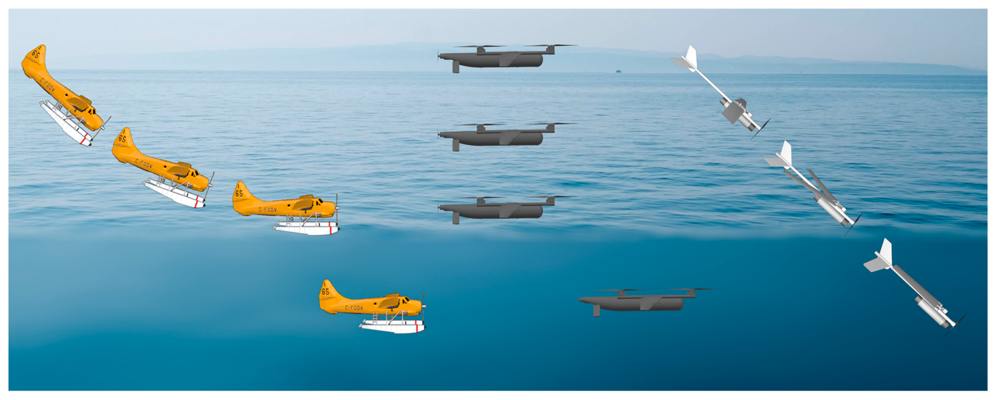
Air-to-water transition modes are also classified into three types: gliding landing, rotor landing, and swooping landing (Figure 14). The gliding and rotor landing modes employ the air propeller to land on the water surface, followed by submerging underwater. In contrast, the vehicle dives into the water from the air in a swooping landing, decelerates, and adjusts its attitude underwater.
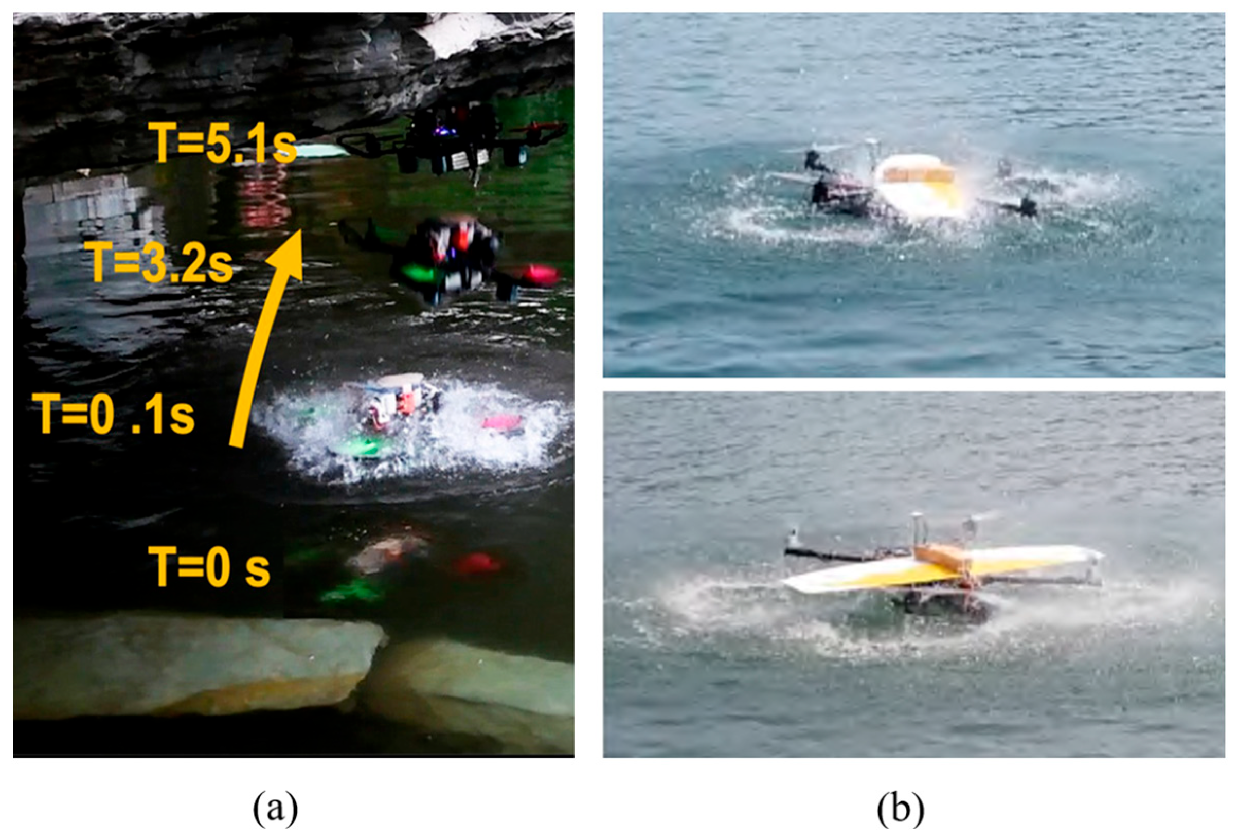
The selection of the water entry and exit mode is determined by the configurations and requirements of UAUVs (Table 2). Rotary-wing and hybrid-wing UAUVs usually take the rotor takeoff and landing (Figure 15) [40,65]. Moreover, this mode is also the simplest and most mature compared to all the other modes.
The water entry and exit modes of fixed-wing and folding-wing UAUVs are relatively changeable. Some UAUVs adopted gliding mode, particularly during landing (Figure 16a) [47,51]. This mode does not require any structural adjustments and requires less thrust and energy. However, it also takes the longest time and is the most sensitive to environmental factors.
If the angle of attack in pull takeoff is too big, an attitude adjustment device is required to assist the vehicle in transitioning to level flight before takeoff, such as the pull takeoff of the fixed-wing vehicle “Eagle Ray” from North Carolina State University (Figure 16a) [47]. Pull takeoff and swooping landing can significantly enhance the environmental adaptability of UAUVs in harsh marine environments with high sea states, and they have been applied to many UAUV prototypes (Figure 16b) [51,62].
In addition, there are some uncommon or unrealized takeoff modes. Jet takeoff is less commonly used on UAUV because water ejection using compressed gas is often disposable. Rapid propulsion takeoff is a continuous and fast water exit method that requires sufficient underwater speed. The vehicle can rely on tremendous inertia to exit the water, which minimize the time spent on the surface. It is difficult to achieve this takeoff mode currently due to the limited capability of underwater propulsion. This mode is expected to be the primary approach for future high-speed folding-wing UAUVs. However, as the water entry and exit speeds increase, stronger structural strength, buffer device design, and hydrophobic material performance are required.

3.2.2. Hydrodynamic Calculation

Although hydrodynamic calculation for vehicles in a single medium is widely applied, little work has been conducted on analyzing the unsteady fluid characteristics during the water-air transition of complex structures. Studies have made considerable progress utilizing theoretical analysis, numerical simulation, and physical tests on water entry and exit of simple objects, such as low-speed flat plates [96,97], spheres [98,99,100,101], cylinders [102,103,104], cones [105], wedges [105,106,107,108], slender symmetric bodies [109,110,111], and high-speed tiny rigid objects [112,113,114,115,116]. These studies have made considerable progress in addressing difficulties related to the calculation of the free surface of the liquid, hydrodynamic characteristics for cavitation, and the impact and vibration of structures. However, the complexity of UAUV shapes introduces three new challenges for water entry and exit calculations and tests.
(1) The stability of the vehicle under real ocean environments during water entry and exit should be valued. Environmental factors such as wind, waves, and currents can have a severe impact on the transition, particularly for small-scale UAUVs. This problem is currently simplified as a pure control problem in the studies of rotary-wing UAUV. The latest research simplifies waves into Airy waves [117], but there is still a lot of simplification or even neglect in the study of wind and wave models [118]. The impact of the environment is uniformly treated as external interference in the control system. After the prototype was manufactured, this method was applied in tests. It successfully enabled stable water exit in level 2 sea conditions. Meanwhile, it significantly reduced the average water exit time by 60% and the average energy consumption by 26%. Due to the lack of response analysis of the vehicle to environmental parameters, it cannot fundamentally improve the water entry and exit performance from shape and structure. It is necessary to focus on the force and motion under different waves and winds through CFD or experiments when the size of the vehicle increases or when it is equipped with fixed wings.
(2) The impact load should be calculated via numerical simulation and experiments should be conducted during water entry to ensure the safety of UAUV structure. The impact load mainly acts on the head and wings. Most of the research focuses on head geometries. For example, Shi et al. [119] simulated the high-speed water entry process of different vehicle heads based on the fluid–solid interaction and analyzed the evolution law of the water entry flow field and impact load. The deformation of the head has been reduced by 50% by optimizing the cone angle. Liu et al. [120] used the coupling Euler-Lagrange method to develop a coupling model for analyzing the impact dynamic response of a vehicle entering the water at a high speed. CFD is the only calculation method used for water entry load analysis for more complex shapes, such as the head of UAUVs [59,121]. The source of impact load on the leading edge of the wing is the same as that on the head, both of which are caused by swooping landing. The impact load on the wing surface mainly comes from the free surface impact during vertical landing.
(3) Water entry and exit trajectory should be considered, which is related to the control design difficulty of UAUV during transition, as well as the stability and maneuverability during and after the transition. The effects of parameters such as vehicle shape, speed [122,123], attitude angle [124], attack angle [125], and rudder angle [126,127] have been studied for simple objects. For instance, using a large slenderness ratio, the blunt head–type can improve vehicle stability during water entry [128,129]. Using the method of preset rudder angle can help the vehicle to turn after entering the water and return to the horizontal position quickly [126,127]. However, no effective methods currently exist to predict water entry and exit trajectories for complex UAUV shapes, particularly those with folding wings. Numerical calculations and experimental research for folding-wing UAUVs are limited to studying the folded and unfolded states separately [53,60].
Addressing these three problems is vital for ensuring stable and reliable water entry and exit capacities for UAUVs. However, current research is limited to regular objects or simplified models. CFD is effective for solving these problems where an accurate mathematical model cannot be established. With advancements in computing power, the calculation accuracy of these three problems will rapidly improve.

3.2.3. Buffered and Load Reduction Design

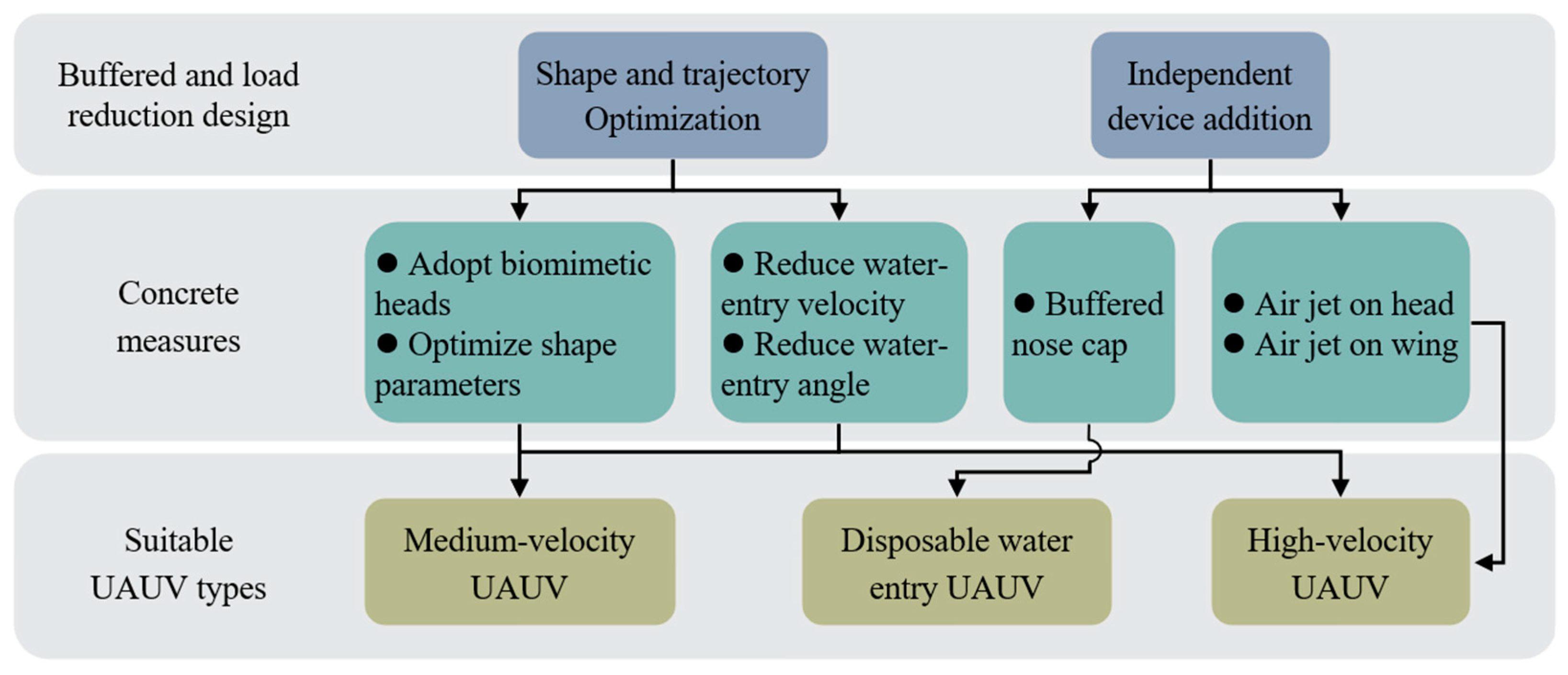
Swooping landing will apply significant impact pressure to the head of the vehicle, which requires a specialized design. At present, two design ideas exist for buffered and load reduction: optimization of shape and trajectory or addition of independent devices (Figure 17).
Sharker et al. [130] found through experiments that the shapes of plunge-diving birds (such as belted kingfisher and northern gannet) can reduce the impact load compared to surface-diving birds (such as Atlantic puffin and common loon). Shi et al. [131] found that the impact pressure is greater when the hemispherical angle of the head shape is larger and the thickness of the shell is smaller. The stress and deformation of different head shapes differ by two times and one time, respectively. In addition, the peak impact pressure is proportional to the square of the water-entry velocity and angle (the angle between the vehicle and the horizontal plane). For medium-velocity UAUVs, optimizing their shape based on biomimetic heads and reducing speed and angle can maintain the impact load within an acceptable range. However, independent devices need to be added for high-velocity UAUVs.
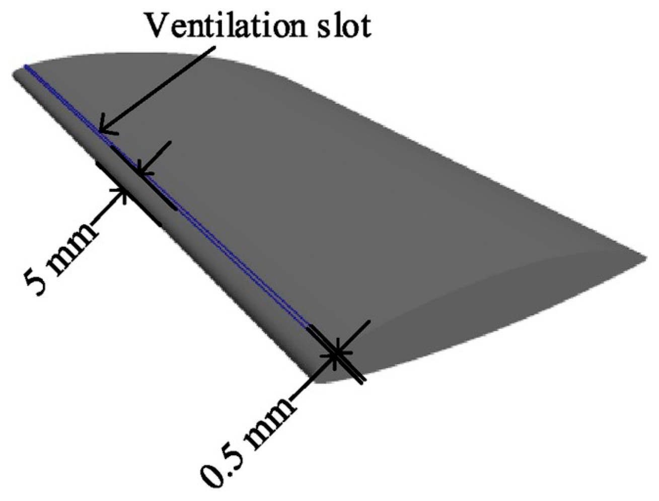
Two types of buffered and load reduction devices exist: a buffer nose cap and ventilation device. The nose cap is a detachable structure equipped at the head of the vehicle. Its shell is composed of unsaturated polyester resin as a matrix and chopped twisting glass fiber as a reinforcing base [132], which can be easily damaged after absorbing energy. The interior of the device is filled with cushioning materials, such as rigid polyurethane foam [133], aluminum foam [134], and polymethacrylimide foam [135]. Compared to this one-time measure, ventilation devices are more suitable for UAUVs, though their effectiveness remains limited at present. Pan and Zhao et al. found that jetting at the head can significantly change the shape of the water entering bubbles, thereby reducing the impact load by more than 0.4 MPa [136,137]. Sun et al. found that slotting along the span direction on the wing of an air jet can also significantly reduce pressure peaks (Figure 18) [138].
Among the approaches to address water entry impact, one straightforward method lies in designing superior impact-resistant materials. Xu et al. proposed a rigid polyurethane foam cushioning structure, which achieves phased absorption of impact energy through density regulation [139]. Define the Froude number when the vehicle enters the water (as shown in Formula (2)).
F r = V 0 g D
V 0 is the initial velocity of the vehicle upon water entry, g denotes the local gravitational acceleration, and D signifies the diameter of the vehicle head. When F r = 84.2 , a cushioning material reduces the maximum indentation deformation by approximately 50% compared to vehicles without cushioning structures. When F r = 112.2 , the cushioning structure prevents the head hull from fracturing. Both Zhang et al. and Zhou et al. suggested realizing gradient attenuation of impact loads via the multi-layer design of composite materials [140,141]. A typical example is the TC4 titanium alloy/ultra-high molecular weight polyethylene laminated structure. However, interlaminar debonding, shear failure, and plastic deformation also lead to the single-use characteristic of composite materials when subjected to water entry impact. Safri et al. proposed confining the impact damage of composite materials to controllable delamination through interface design [142]. Qiao et al. recommended embedding fiber Bragg grating (FBG) sensors in composite materials to real-time monitor strain distribution and damage evolution after water entry impact [143]. These measures can ensure the effectiveness and reusability of impact-resistant materials for UAUVs during the water entry process.

3.3. Propulsion and Power System

The development of propulsion and power systems for UAUVs has received limited attention, likely due to their relatively small size and the shortage of researchers specializing in energy and power engineering. The development can be advanced by promoting effective communication between different disciplines and specialties. To this end, some design improvements for integrated sea–air propulsion and power systems are recommended herein.

3.3.1. Propulsion

The majority of current UAUV prototypes use propeller propulsion. However, due to the significant difference between the physical properties of air and water, air propellers tend to have higher speeds, larger diameters, and smaller disk coefficients than underwater propellers. Consequently, underwater propellers cannot be used in the air, and the propulsion effect of air propellers is reduced underwater. Zufferey et al. found that using the same combination of electric motors and propellers, the optimal total efficiency of UAUVs in the air was 10.2 times than that in water [14]. This issue can be addressed using four solutions, all of which have been applied to prototypes listed in Table 3.
The first solution involves equipping UAUVs with both air and underwater propellers, ensuring superior aerial and underwater propulsion efficiency. This is the most commonly used method; however, it increases the difficulty of optimizing the structure, weight, and shape of UAUVs.
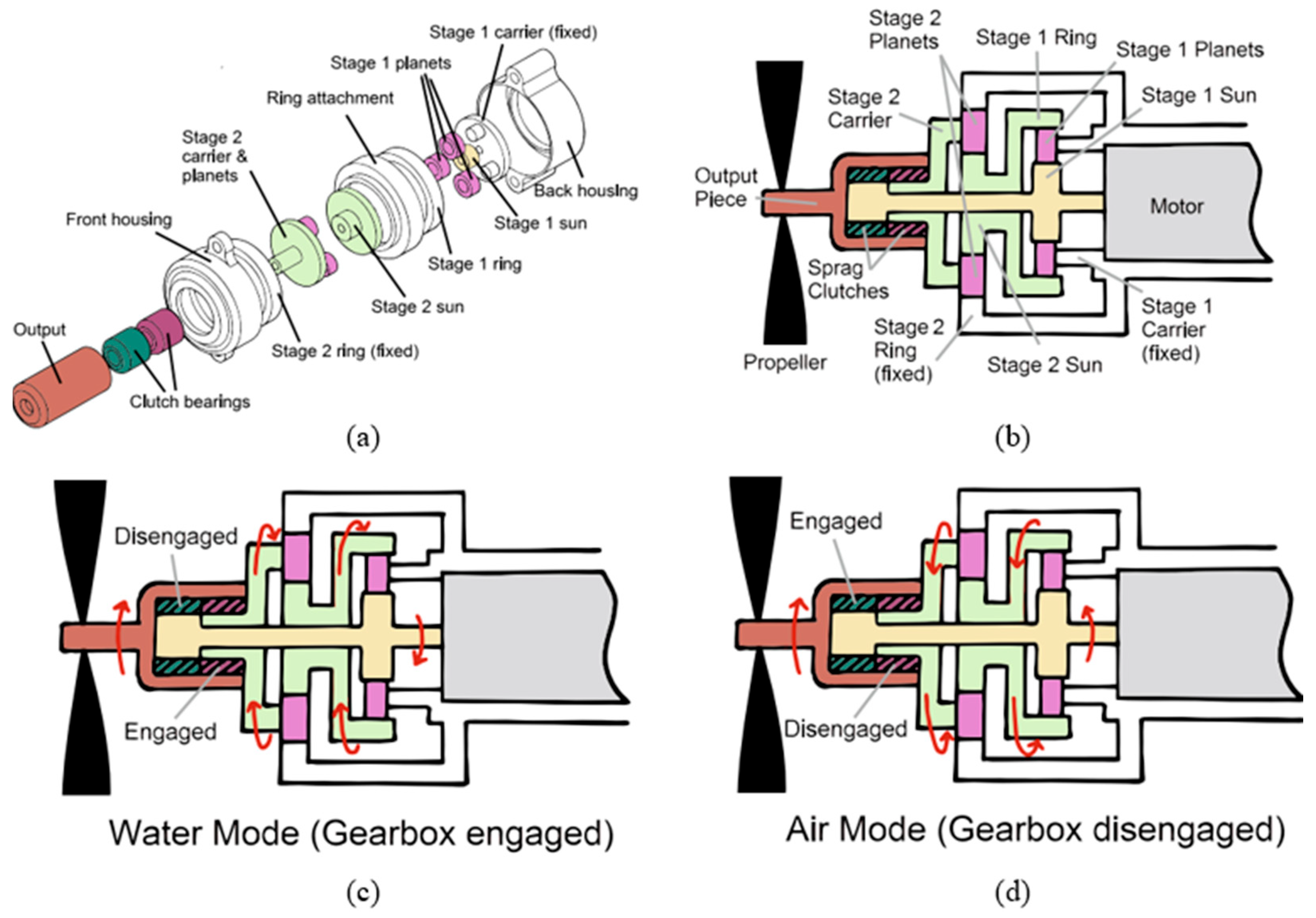
The second solution is to only use air propellers, which has also been applied in many prototypes although most prototypes using this solution often overlook the efficiency of underwater propulsion. Wei et al. used an air propeller on a fixed-wing UAUV to generate a maximum force of 25 N at full throttle in the air, with a power of 1500 W [51]. When rotating in reverse at a lower speed underwater, it can also generate a stable force of 23 N, with a power of 850 W. Unique transmission devices are designed to improve the underwater efficiency of aerial propellers. Tan et al. proposed a specific method (Figure 19) [144]. The method involves reversing the motor underwater and using a gearbox for deceleration. With this method, the efficiency of underwater propulsion improved by an order of magnitude (from 5% to nearly 50%). This efficiency even reached the level of air propulsion efficiency of the same power system without the gearbox. Note that the rotation direction of the propeller was always the same, and the motor was reversed. This method is currently only applied to a micro UAUV prototype, but it has strong application potential for larger UAUVs and is worth studying.
The remaining two solutions in Table 3 are not widely used. The third solution involves designing a universal propeller based on the characteristics of both aerial and underwater propellers. For air propellers, underwater thrust can be improved by reducing the diameter, increasing the number of propellers, increasing the disk coefficient, and using a duct to increase pressure. For instance, the Shenyang Institute of Automation Chinese Academy of Sciences developed an aerial-underwater dual-use duct propeller that has practical value [64,145]. The thrust factor in the air reaches 2.48 × 10⁻⁴, and it reaches 1.47 × 10⁻⁴ underwater. The maximum thrust in the air can reach 55 N, and the thrust underwater can reach 245 N.
The fourth solution involves designing a deformable propeller that meets the thrust demand in both the air and underwater environments under a similar rotational speed. For example, Li et al. designed low-cost folding propellers that could adaptively fold underwater and passively unfold in the air [40]. Holding the throttle of the motors constant (50%), the rotational speed of the self-folding propellers changed from 1400 rpm (underwater) to 9600 rpm (in air) within 0.54 s.
For low-speed UAUVs used underwater, using only an aerial propeller is the most convenient approach. However, if underwater performance needs to be considered, air and underwater propellers must be used in combination. However, in the future, designing transmission devices based on a single air propeller will be the ideal solution.

3.3.2. Hybrid Power System

Currently, the UAUV is still in the technical verification stage, and most successfully developed prototypes use batteries as energy sources. For laboratory prototypes, electric power can be used to reduce research complexities. However, the power system must be optimized when UAUVs are used in practical applications.
Researchers from China Aeroengine Research Institute analyzed the volume and mass capacity density of high-performance batteries, including lithium-ion batteries and silver aluminum oxide batteries [146]. They found that these batteries are not as efficient as thermal power fuels. However, the level of electric power and thermal power is equivalent in terms of the specific energy of the whole power and propulsion system because of the simpler structure of the electric power propulsion system. Therefore, the reliability of other systems can be verified using pure electric solutions in the laboratory prototypes. However, in tasks requiring high aerial performance, hybrid power systems should be used in UAUVs.
To this end, a hybrid power system design is proposed for medium UAUVs that integrates a direct battery drive for underwater propulsion and a hybrid engine and battery drive for aerial propulsion (Figure 20). This integrated design considerably improves air endurance compared to pure electric solutions. Incorporating an engine for underwater propulsion poses significant design challenges that involve using built-in oxidants or a water reaction engine to address the lack of air, an increased exhaust compression ratio and combustion chamber pressure to overcome high back pressure, and a fluid dynamic seal. These increase the cost and complicate the systems. If the engine cannot be used underwater, only the static sealing needs to be ensured, which is relatively simple. The designed hybrid power system considers good cost performance. When the flight speed and system cost are both low, using a piston engine is appropriate. Using a turbofan or turbojet engine is more appropriate when the speed increases.

3.4. Control Systems

There are the most papers on UAUV control systems compared to other aspects, with nearly 20 published in 2023 alone. The vast majority of them are dynamic modeling and controller design related to air-water transition or water-air transition.
The different working environments of UAUVs vary greatly, so it is inefficient or even unrealistic to pursue a unified controller or control system when implementing automatic control. During underwater navigation, aerial flight, and transition, different controllers are often required, and even the water entry and exit processes require different controllers. Most UAUVs use separate air and underwater control systems. Mature UAV flight control systems are used in the air, with pre-programmed AUV control systems used underwater. As the applications of these two components are already fairly mature, current design endeavors focus on the two external aspects introduced below.

3.4.1. Optimization of Underwater Controllers

The optimization of underwater control system mainly focuses on the different structures of UAUVs compared to traditional AUVs. Hybrid-wing and fixed-wing UAUVs must add ailerons to reduce lift. The combination of ailerons and elevators can accelerate the ascent and descent of the longitudinal plane. The ailerons can act alone or in conjunction with the rudders to complete the turning, which draws inspiration from the principle of fixed-wing aircraft turning. The optimal configuration of ailerons and other control surfaces during underwater maneuvering of UAUVs can be found by combining optimal control methods such as linear quadratic regulator (LQR). There is currently no relevant work published on this part.
The structure of the rotary-wing UAUVs is very different from that of traditional AUVs, so there are many designs and optimizations for their underwater control system. Due to the significant coupling effect between the rotor and the fuselage underwater, it is necessary to decouple the system and establish an accurate dynamic model [147]. The rotary-wing UAUV is an underactuated system, and as the underwater damping increases, the attitude tracking error will also increase, posing a threat to the accuracy and reliability of the control system [148]. We can draw on the experience from quadrotor UAVs and use a multivariable super-twisting-like algorithm for compensation [149].
Rotary-wing UAUV has a complex shape. This complexity comes from the presence of propellers, arms, and electrical machinery. The complex shape makes it susceptible to environmental interference, such as internal waves and underwater obstacles. Additionally, the system has relatively high uncertainty. Therefore, improving the robustness of the control system is necessary. The use of sliding mode control (SMC) can overcome internal and external interference, achieve underwater position and attitude control, and trajectory tracking [150,151]. To suppress the inherent chattering of SMC, the fast integral terminal SMC control law, a variable-gain robust exact differentiator observer, and a feedforward neural network are used [152].
When multiple UAUVs need to conduct cooperative operations underwater, there is an increased demand for control precision and robustness. Underwater acoustic communication features low bandwidth (1–100 kbps) but long transmission distance, while underwater optical communication offers higher bandwidth (10 Mbps) but shorter transmission distance (≤100 m) [153]. The adoption of hybrid acoustic-optical communication can effectively support the underwater high-precision control of multi-UAUV systems. Viadero-Monasterio et al. proposed a static output feedback (SOF) controller for multi-vehicle trajectory tracking [154]. This controller does not rely on high-precision state measurements and can guarantee closed-loop control stability under communication delays [155]. These two characteristics make it suitable for the underwater operating scenarios of multi-UAUV systems. Rehman drew inspiration from a similar approach to handling parameter uncertainty, and ultimately achieved motion control of multiple heavy-load underwater vehicles with a lateral error of less than 0.2 m [156].

3.4.2. Transition Controllers

A transition controller must also be designed. The water entry and exit of UAUVs are strongly nonlinear processes, particularly in rough sea conditions with significant wind and waves. The position and attitude of the UAUV can experience severe jitter, highlighting the importance of solving the control problem during water entry and exit.
Zeng et al. identified common features of water entry and exit control system designs by investigating numerous rotary-wing UAUV prototypes [15]. The control technology can be studied by exploring the modeling of UAUVs, particularly for newly developed prototypes. Currently, most rotary-wing prototypes that have been successfully tested use the classical PID control strategy. However, the PID controller is susceptible to generating a jitter due to environmental changes [157].
Some researchers have added state observers to control systems to estimate the most uncertain factors during the transition, such as time-varying interference from wave and wind, and nonlinear dynamic models [158,159,160,161]. The integration of feedback linearization, robust differentiator, and observer is also worth learning from for the control optimization method of a UAV under wind disturbance [162]. These methods significantly enhances the anti-interference performance of the system. Some researchers have also achieved good results in dealing with uncertainty using adaptive technology [163]. Using piecewise linearization to handle complex control objective functions or additional disturbances during the transition process is also a good method to save computational costs [164,165].

3.4.3. Unified Control Frameworks

Most existing Unmanned Aerial-Aquatic Vehicle (UAUV) control systems adopt a phase-separated design. Although this design leverages mature single-medium control technologies, it suffers from issues of mode switching instability and lack of global robustness. Moreover, separated controllers fail to address cross-medium coupled disturbances (e.g., wave-induced slamming during the transition phase) [157,166]. Recent studies have begun to explore unified control frameworks. Unified disturbance estimation is achieved via the neural network extended state observer [159], which uniformly estimates unmeasurable states and disturbances across all phases. Additionally, unified control laws such as the adaptive nonsingular fast terminal SMC utilize a single sliding surface to achieve finite-time convergence for aerial attitude stabilization and underwater position tracking [163].
However, unified frameworks still face key challenges, such as inaccurate air-water coupling modeling and adaptive parameter saturation. To address these challenges and enhance robustness, two feasible strategies are proposed. One is to extend the linear switching model [163] to a multi-cell linear parameter varying (LPV) model by integrating wave force models and CFD data into the vertices of LPV cells. More accurate parameter interpolation can be realized. The other is to combine disturbance observers [158,159,167] with adaptive SMC [168] to form a dual-layer anti-disturbance strategy.

4. Application Prospect and Future Development Trend

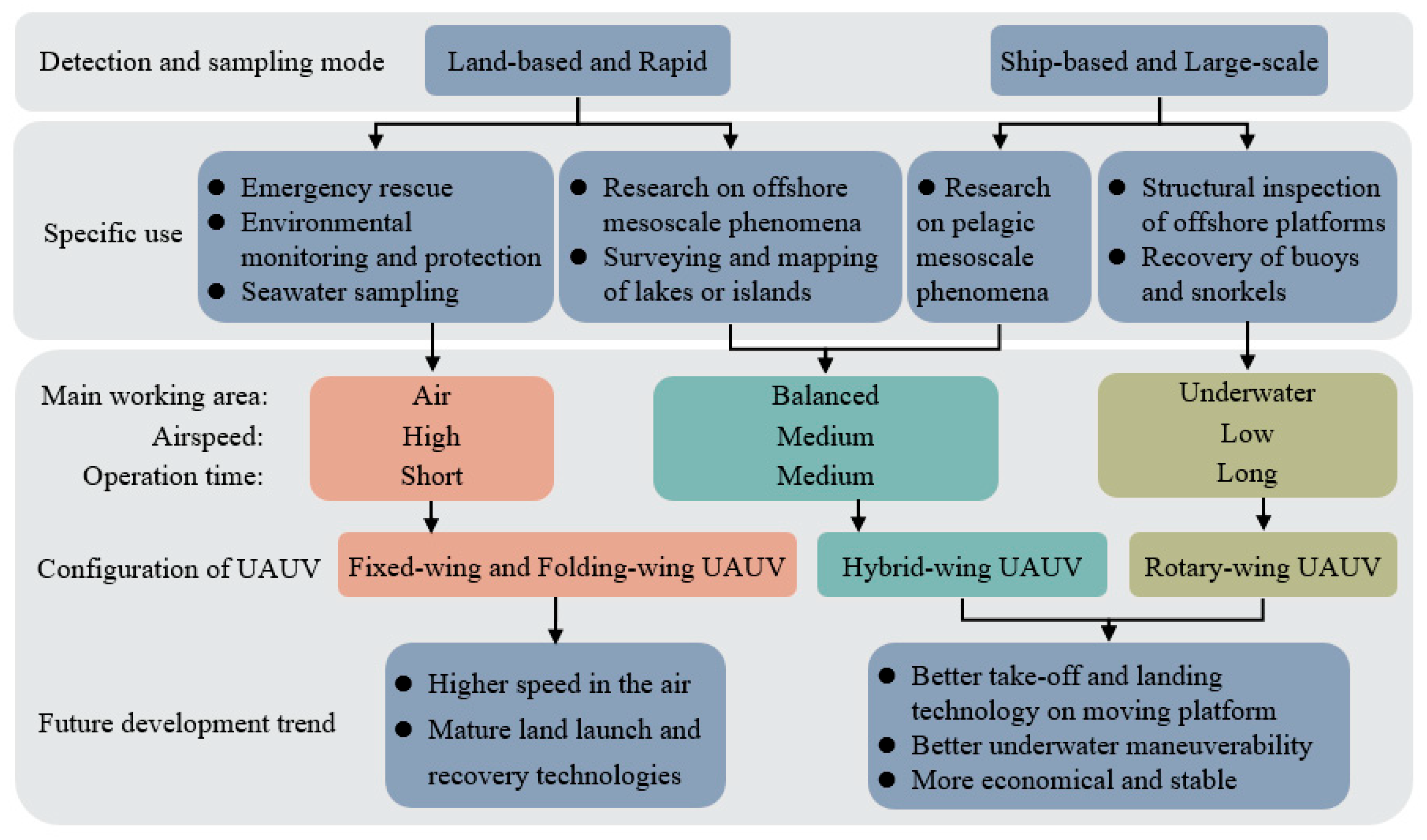
The development of practical applications for UAUVs is still lacking, which can be addressed by analyzing the needs of related fields and exploring their potential applications. Civilian UAUV applications can be mainly divided into two directions. One is the rapid detection and sampling, and the other is the large-scale detection and sampling.

4.1. Prospects for Civil Application

4.1.1. Rapid Detection and Sampling

UAUVs can be deployed for missions far from their bases, including rapid integrated air-underwater remote sensing, air-underwater environmental monitoring, and maritime distress search. Their ability to perform these tasks relies on rapid aerial flight and flexible underwater maneuverability. The UAUV needs to fly quickly to the target for detection and sampling with strict time requirements. Such missions are more common in actions led by government departments such as emergency rescue, environmental protection, and ocean monitoring.
While some UAVs and AUVs have demonstrated certain functionalities in these tasks, UAUVs are better suited to complete them effectively. For example, unmanned helicopters equipped with water collection equipment were used to collect water samples from a river to determine their quality [169]. Rotary-wing UAVs that float on the surface were used to deploy underwater sonar sensors [170], and joint coral reef observations were performed using air and underwater vehicles [171]. However, UAUV technology can considerably improve the effectiveness of these tasks by reducing the design difficulty and weight of water collection equipment, thereby increasing the depth of water extraction and sensor placement and improving the accuracy of sensor placement.

4.1.2. Large-Scale Detection and Sampling

In the large-scale detection and sampling task, the target distance is close to the UAUV base, but higher requirements are placed on the continuous detection and sampling. Such tasks are often observed in marine scientific research and engineering projects led by research institutes equipped with large scientific research vessels and oil companies with platforms.
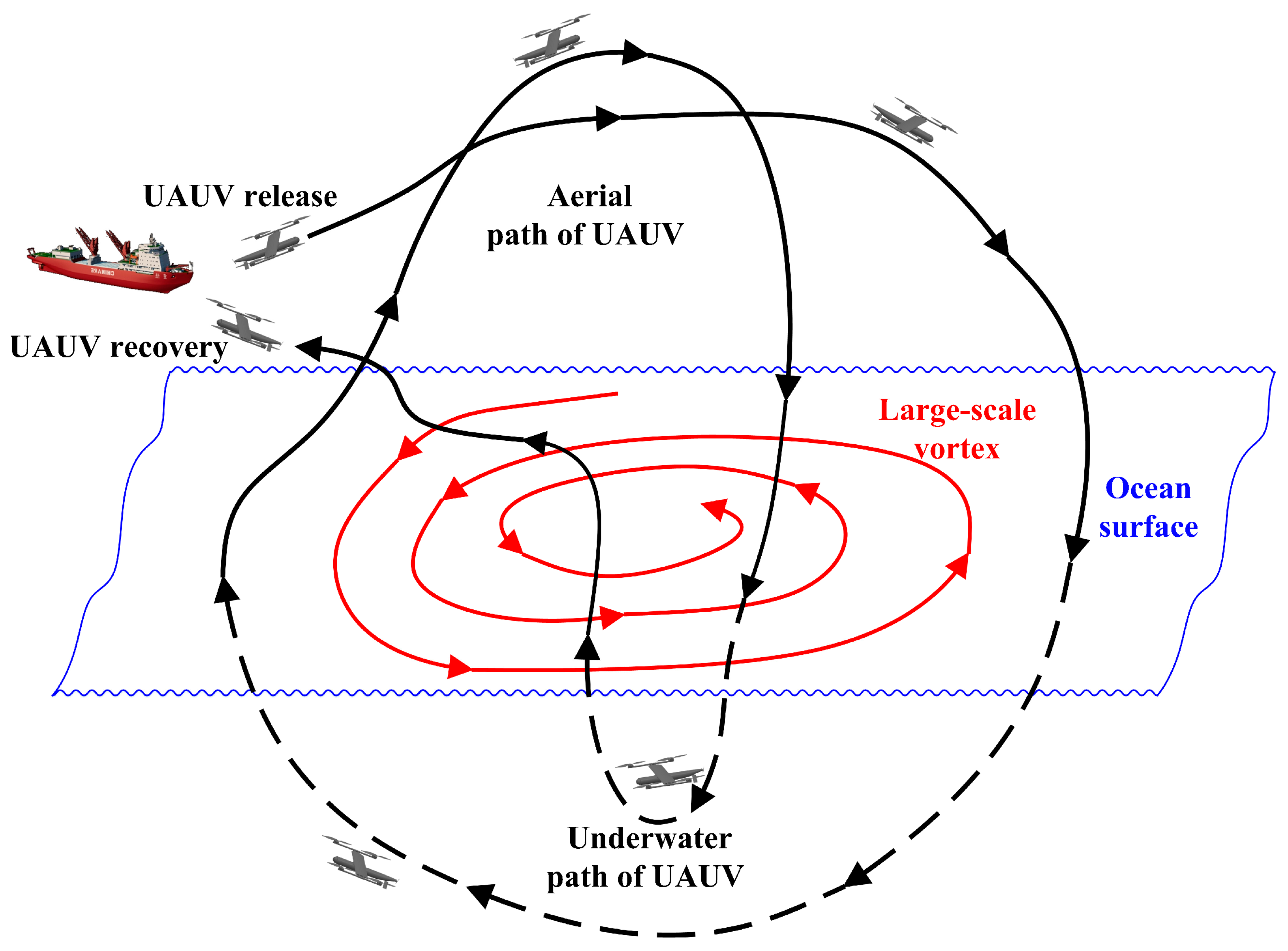
UAUVs carried on scientific research ships can increase the detection range along the detection route. Researchers from SJTU have proposed using UAUVs for three-dimensional observations of the ocean and atmospheric multi-physics environments. Different observation paths can be flexibly designed for different observation objects, such as the integrated observation of ocean and air fronts formed by cold and warm currents and cold and warm air masses (Figure 21) as well as that of large-scale vortices (Figure 22). This rapid and large-scale sea area exploration can promptly provide a vast amount of data and sample information for physical ocean, ocean biology, ocean chemistry, and other research areas as well as external calibration for remote sensing satellites.
Furthermore, Zufferey et al. suggested that such UAUVs can realize the detection and maintenance of platforms with lower cost, higher efficiency, and more security compared to traditional methods (e.g., human-driven sensors, direct rope access, and pure underwater robots) [14].
Some researchers have suggested using air-dropped or air-launched underwater vehicles for conducting rapid response surveys in a wide range of ocean areas, such as the Atlantic Meridional Transect, the Porcupine Abyssal Plain, the Meridional Overturning Circulation, and sudden pollutant leakage and algal blooms [172,173]. The use of UAUVs can further expand these tasks and increase the detection range, accelerating response and detection.
In addition, flying submarines can make new contributions to tourism, search, and rescue, and other civil fields.

4.2. Future Development

The overall design of the UAUV prototype including basic performance parameters, exterior, and structural design should be aimed at meeting specific current use cases. We have proposed the requirements for the main working area, airspeed, and operating time from the two categories of civil applications mentioned earlier and their specific uses (Figure 23). Based on these requirements, identify suitable UAUV configurations and propose future development trends.
Significant gaps can be observed when evaluating different configurations of UAUVs based on technology readiness level (TRL), manufacturing readiness level (MRL), and market readiness level (MaRL) [174,175]. All three evaluation criteria are scaled from Level 1 (lowest readiness) to Level 9 (highest readiness). Taking the most advanced UAUV prototypes (those marked with four “Y” in Table 1) as the benchmark for rating. The TRL is rated Level 7, which means these prototypes have completed system-level testing in natural environments. MRL is rated Level 4, which means the critical manufacturing processes have been developed and preliminarily tested. The MaRL is rated Level 2, which means target market segments have been defined. It is evident that among the three readiness dimensions, the MaRL is currently the lowest.
To enable the future development trends to be translated into practical deployment solutions, it is necessary to further clarify the core constraints that may hinder this transition. These constraints not only involve technical adaptability but also encompass economic factors such as cost controllability and market-oriented commercialization feasibility. Table 4 systematically sorts out the differences in research and development costs (R&D costs), manufacturing costs, practical deployment obstacles, and commercialization bottlenecks among various configurations.
R&D cost (Research and Development cost) of Unmanned Aerial-Aquatic Vehicles (UAUVs) cannot generally be measured solely by monetary value; it also includes time and labor costs incurred throughout the R&D process. The R&D process of a UAUV typically involves stages such as design, prototype manufacturing, testing, and optimization, among which the design and testing stages account for the highest proportion of the total R&D cost. Rotary-wing UAUVs have the lowest R&D cost due to the reuse of mature UAV technologies. Folding-wing and Flapping-wing UAUVs incur the highest R&D cost, because their designs as aerial vehicles are inherently more complex.
Manufacturing cost refers to the processing and assembly cost of a single UAUV product after the design is finalized, and its level mainly depends on the degree of component customization. Consistent with the R&D cost trend, Rotary-wing UAUVs also have the lowest manufacturing cost. They can make extensive use of commercial UAV components. Folding-wing and Flapping-wing UAUVs have the highest manufacturing cost. Notably, the R&D costs of all UAUVs are far higher than their manufacturing costs, with a difference of up to five times or more. This aligns with the cost characteristics of other industrial products such as pharmaceuticals, consumer electronics, and automobiles.
Practical deployment barriers stem from technical defects exhibited by various prototypes, focusing on three dimensions: environmental adaptability and functional limitations. Commercialization barriers, on the other hand, revolve around cost controllability, market adaptability, and technical maturity.
Practical deployment barriers of UAUVs can be minimized by identifying suitable application scenarios and resolved through technological innovations. Commercialization barriers, by contrast, require resolution through a holistic approach. It is critical to vigorously integrate current UAUV R&D resources and conduct focused on key models. This integration not only helps reduce R&D costs but also accelerates the improvement of technical maturity. Against the backdrop of enhanced technical maturity, competition from AUVs and UAVs can be addressed with policy support. Additionally, the commercial enterprises are essential. Their involvement enables accurate identification of practical application requirements and further enhances the commercial value of UAUVs. They can bridge the gap between laboratory prototypes and market-oriented products.

5. Conclusions

UAUVs have been under development for nearly a century since the concept of a diving plane was first introduced in 1934. Despite its long history, the practical application of UAUVs has been hindered by technical challenges. In the past ten years, UAUV development has entered a new stage. This progress benefits from the mature technologies of UAVs and AUVs. However, the development of practical applications falls far behind technological advancement. This lag is caused by the linear development mode. Only 36% of the 33 core prototypes analyzed in this review have completed all the verification, but 0% of them have entered the practical application stage. Our review first proposes the transformation of development modes of UAUVs, and then summarizes the research progress, design foci, technical difficulties, application prospects, and development trends of UAUVs in detail.
First, UAUVs are classified and their research progress was systematically summarized in different categories. The majority of prototypes are inefficient, and only a few can be used for air flight, underwater cruising, and multiple water entry and exit.
Then, four design foci such as basic appearance and structure, water entry and exit, propulsion and power system, and control system are proposed. Design guidance is developed based on requirements for each design focus, and potential solutions are proposed to address the technical difficulties.
Finally, the application prospects of UAUVs in the civilian fields were analyzed. The adaptive UAUV configuration and future development trends were outlined for each specific use. It is predicted that under the market-pull and technology-push interactive mode, the cost of civilian UAUV detection tasks will decrease by 35% in the next 5 years, and the proportion of practical prototypes will increase to 100%.
The UAUV requires a multidisciplinary approach in its research and development, based on fields such as aviation, ship, oceanography, robotics, energy, biology, and machinery. Mutual communication and knowledge sharing can facilitate the integration of multidisciplinary technologies, driving the practical, high-speed, and large-scale development of UAUVs. Moreover, the application field of UAUVs will be considerably expanded due to the diversity of researchers’ backgrounds.

Author Contributions

Conceptualization, Z.W. and W.H.; methodology, H.Z. and L.D.; investigation, H.Z., Z.W. and Y.T.; resources, Z.W. and W.H.; data curation, H.Z.; writing—original draft preparation, H.Z. and L.D.; writing—review and editing, H.Z. and Z.W.; visualization, H.Z.; project administration, Z.W. All authors have read and agreed to the published version of the manuscript.

Funding

This research was funded by National Natural Science Foundation of China, grant number 5237132. The APC was funded by National Natural Science Foundation of China, grant number 5237132.

Institutional Review Board Statement

Not applicable.

Informed Consent Statement

Not applicable.

Data Availability Statement

The original contributions presented in this study are included in the article. Further inquiries can be directed to the corresponding author.

Conflicts of Interest

The authors declare no conflict of interest.

References

  1. Webster, P.J.; Lukas, R. TOGA COARE: The coupled ocean–atmosphere response experiment. Bull. Am. Meteorol. Soc. 1992, 73, 1377–1416. [Google Scholar] [CrossRef]
  2. Zhao, B.; Tang, J.; Lei, X.; Zhang, X.; Duan, W.; Li, H.; Gao, Z.; Qian, C.; Bao, X.; Luo, J.; et al. Progress on the experiment of a multi-platform collaborative field campaign on offshore typhoon. Adv. Earth Sci. 2022, 37, 771. [Google Scholar]
  3. Murphy, R.R.; Steimle, E.; Griffin, C.; Cullins, C.; Hall, M.; Pratt, K. Cooperative use of unmanned sea surface and micro aerial vehicles at Hurricane Wilma. J. Field Robot. 2008, 25, 164–180. [Google Scholar] [CrossRef]
  4. Tian, E.; Li, Y.; Ma, T.; Liao, Y.; Li, Y.; Cao, J. Design and experiment of a sea-air heterogeneous unmanned collaborative system for rapid inspection tasks at sea. Appl. Ocean Res. 2024, 143, 103856. [Google Scholar] [CrossRef]
  5. Moltmann, T.; Turton, J.; Zhang, H.M.; Nolan, G.; Gouldman, C.; Griesbauer, L.; Wills, Z.; Piniellan, A.; Barrell, S.; Zhang, Y.; et al. A global ocean observing system (GOOS), delivered through enhanced collaboration across regions, communities, and new technologies. Front. Mar. Sci. 2019, 6, 291. [Google Scholar] [CrossRef]
  6. Petrov, G. Flying submarine. J. Fleet 1995, 3, 52–53. [Google Scholar]
  7. Drews, P.L.J.; Neto, A.A.; Campos, M.F.M. A survey on aerial submersible vehicles. In Proceedings of the IEEE/OES Oceans Conference, Bremen, Germany, 11–14 May 2009. [Google Scholar]
  8. Handler, E.H. The flying submarine. Proceedings 1964, 4, 144–146. [Google Scholar]
  9. Donald, V.R. Flying Submarine. U.S. Patent 3092060 A, 4 April 1963. [Google Scholar]
  10. Reid, B.D. The Flying Submarine: The Story of the Invention of the Reid Flying Submarine, RFS-1; Heritage Books: Beverly Hills, CA, USA, 2012. [Google Scholar]
  11. He, Z.; Zheng, Z.S.; Ma, D.; Zhou, Q. Development of foreign trans-media aircraft and its enlightenment to China. Ship Sci. Technol. 2016, 38, 152–157. [Google Scholar]
  12. Van Blyenburgh, P. Unmanned aircraft systems: The current situation. In Proceedings of the Autonomous Surface Ships Symposium 2008, Quebec City, QC, Canada, 23–25 June 2008; Association Technique Maritime Aéronautique Ronautique: Paris, France, 2008; pp. 1–7. [Google Scholar]
  13. Yang, X.; Wang, T.; Liang, J.; Yao, G.; Liu, M. Survey on the novel hybrid aquatic–aerial amphibious aircraft: Aquatic unmanned aerial vehicle (AquaUAV). Prog. Aerosp. Sci. 2015, 74, 131–151. [Google Scholar] [CrossRef]
  14. Zufferey, R.; Siddall, R.; Armanini, S.F.; Kovac, M. Between Sea and Sky: Aerial Aquatic Locomotion in Miniature Robots; Springer: Berlin/Heidelberg, Germany, 2022. [Google Scholar]
  15. Zeng, Z.; Lyu, C.; Bi, Y.; Jin, Y.; Lu, D.; Lian, L. Review of hybrid aerial underwater vehicle: Cross-domain mobility and transitions control. Ocean Eng. 2022, 248, 110840. [Google Scholar] [CrossRef]
  16. Yao, G.; Li, Y.; Zhang, H.; Jiang, Y.; Wang, T.; Sun, F.; Yang, X. Review of hybrid aquatic-aerial vehicle (HAAV): Classifications, current status, applications, challenges and technology perspectives. Prog. Aerosp. Sci. 2023, 139, 100902. [Google Scholar] [CrossRef]
  17. Zatout, M.S.; Rezoug, A.; Rezoug, A.; Baizid, K.; Iqbal, J. Optimisation of fuzzy logic quadrotor attitude controller–particle swarm, cuckoo search and BAT algorithms. Int. J. Syst. Sci. 2022, 53, 883–908. [Google Scholar] [CrossRef]
  18. Saleem, O.; Kazim, M.; Iqbal, J. Robust Position Control of VTOL UAVs Using a Linear Quadratic Rate-Varying Integral Tracker: Design and Validation. Drones 2025, 9, 73. [Google Scholar] [CrossRef]
  19. Saleem, O.; Tanveer, A.; Iqbal, J. Adaptive Reconfigurable Learning Algorithm for Robust Optimal Longitudinal Motion Control of Unmanned Aerial Vehicles. Algorithms 2025, 18, 180. [Google Scholar] [CrossRef]
  20. Yang, R.Q.; Sun, J.; Zhang, Y. Rapid Surveying and Mapping Based on the Digital Aerial Photographic System Mounted on Unmanned Aerial Vehicle. Remote Sens. Inf. 2010, 3, 4. [Google Scholar]
  21. Pérez-Ortiz, M.; Peña, J.M.; Gutiérrez, P.A.; Torres, J.; Hervas, C.; Lopez, F. Selecting patterns and features for between-and within-crop-row weed mapping using UAV-imagery. Expert Syst. Appl. 2016, 47, 85–94. [Google Scholar] [CrossRef]
  22. Schneider, W., Jr. Defense Science Board Study on Unmanned Aerial Vehicles and Uninhabited Combat Aerial Vehicles; Office of the Under Secretary of Defense: Washington, DC, USA, 2004. [Google Scholar]
  23. Baba, Y.; Takano, H.; Miyamoto, S.; Ono, K. Air combat guidance law for an UCAV. In Proceedings of the 1st UAV Conference, Portsmouth, VA, USA, 20–23 May 2002; p. 3427. [Google Scholar]
  24. Ruixuan, W.; Xueren, L. UAV System and Operational Use; National Defense Industrial Press: Beijing, China, 2009. [Google Scholar]
  25. Boccardo, P.; Chiabrando, F.; Dutto, F.; Giulio Tonolo, F.; Lingua, A. UAV deployment exercise for mapping purposes: Evaluation of emergency response applications. Sensors 2015, 15, 15717–15737. [Google Scholar] [CrossRef] [PubMed]
  26. Zhang, Y.; Tao, P.; Liang, S.X.; Liang, W.L. Research on Application of UAV RS Techniques in Forest Inventories. J. Southwest For. Univ. 2011, 31, 49–53. [Google Scholar]
  27. Jin, W.; Ge, H.L.; Du, H.Q.; Xu, X.J. A Review on Unmanned Aerial Vehicle Remote Sensing and Its Application. Remote Sens. Inf. 2009, 1, 88–92. [Google Scholar]
  28. Zhao, P.; Shen, T.Z.; Shan, B.T. The Application of Remote Sensing System for Micro UAV Based on CMOS Image Sensor. Acta Photonica Sin. 2008, 37, 1657–1661. [Google Scholar]
  29. Liu, Q.Y.; Liu-Hua, X.U.; Shen, C.L.; Wang, L.P. Research on key technology of digital photogrammetry based on UAV remote sensing image. Sci. Surv. Mapp. 2010, 35, 28–30. [Google Scholar]
  30. Tang, M.W.; Dai, L.H.; Lin, C.H.; Wang, F.D.; Song, F.G. Application of Unmanned Aerial Vehicle in Inspecting Transmission Lines. Electr. Power 2013, 46, 35–38. [Google Scholar]
  31. Ping, J.T.K.; Ling, A.E.; Quan, T.J.; Dat, C.Y. Generic unmanned aerial vehicle (UAV) for civilian application—A feasibility assessment and market survey on civilian application for aerial imaging. In Proceedings of the 2012 IEEE Conference on Sustainable Utilization and Development in Engineering and Technology (Student), Kuala Lumpur, MY, USA, 6–9 October 2012; IEEE: New York, NY, USA, 2012; pp. 289–294. [Google Scholar]
  32. Chen, Y.; Lian, L.; Huang, H.C.; Yang, W.J.; Song, J.B. Fundamentals of Marine Technology; China Ocean Press: Beijing, China, 2018. [Google Scholar]
  33. Woods Hole Oceanographic Institution. HOV Deep Sea Challenger. Available online: http://www.whoi.edu/main/deepseachallenger (accessed on 14 April 2025).
  34. Zha, J.; Thacher, E.; Kroeger, J.; Taylor, C.N.; Duraisamy, K. Towards breaching a still water surface with a miniature unmanned aerial underwater vehicle. In Proceedings of the 2019 International Conference on Unmanned Aircraft Systems (ICUAS), Atlanta, GA, USA, 11–14 June 2019; IEEE: New York, NY, USA, 2019; pp. 1178–1185. [Google Scholar]
  35. Hopkins University Applied Physics Laboratory. New UAV Can Launch from Underwater for Aerial Missions. 2016. Available online: https://www.jhuapl.edu/PressRelease/160317#addsearch=cracuns (accessed on 14 April 2025).
  36. Chen, Q.; Zhu, D.; Liu, Z. Attitude control of aerial and underwater vehicles using single-input FUZZY P+ ID controller. Appl. Ocean Res. 2021, 107, 102460. [Google Scholar] [CrossRef]
  37. Bershadsky, D.; Haviland, S.; Valdez, P.E.; Saldanha, N. Design considerations of submersible unmanned flying vehicle for communications and underwater sampling. In Proceedings of the OCEANS 2016 MTS/IEEE Monterey, Monterey, CA, USA, 19–23 September 2016; IEEE: New York, NY, USA, 2016; pp. 1–8. [Google Scholar]
  38. Alzu’bi, H.; Mansour, I.; Rawashdeh, O. Loon copter: Implementation of a hybrid unmanned aquatic–aerial quadcopter with active buoyancy control. J. Field Robot. 2018, 35, 764–778. [Google Scholar] [CrossRef]
  39. Bai, Y.; Jin, Y.; Liu, C.; Zeng, Z.; Lian, L. Nezha-F: Design and Analysis of a Foldable and Self-Deployable HAUV. IEEE Robot. Autom. Lett. 2023, 8, 2309–2316. [Google Scholar] [CrossRef]
  40. Li, L.; Wang, S.; Zhang, Y.; Wainwright, D.K.; Kenaley, C.P.; Gong, Z.; Liu, Z.; Liu, H.; Guan, J.; Wang, T.; et al. Aerial-aquatic robots capable of crossing the air-water boundary and hitchhiking on surfaces. Sci. Robot. 2022, 7, eabm6695. [Google Scholar] [CrossRef] [PubMed]
  41. Horn, A.C.; Pinheiro, P.M.; Silva, C.B.; Souto, H.T.; Santos, R.L. A study on configuration of propellers for multirotor-like hybrid aerial-aquatic vehicles. In Proceedings of the 2019 19th International Conference on Advanced Robotics (ICAR), Belo Horizonte, Brazil, 2–6 December 2019; IEEE: New York, NY, USA, 2019; pp. 173–178. [Google Scholar]
  42. Mercado, D.; Maia, M.; Diez, F.J. Aerial-underwater systems, a new paradigm in unmanned vehicles. J. Intell. Robot. Syst. 2019, 95, 229–238. [Google Scholar] [CrossRef]
  43. Chen, G.; Liu, A.; Hu, J.; Feng, J.; Ma, Z. Attitude and altitude control of unmanned aerial-underwater vehicle based on incremental nonlinear dynamic inversion. IEEE Access 2020, 8, 156129–156138. [Google Scholar] [CrossRef]
  44. Tan, Y.H.; Chen, B.M. A morphable aerial-aquatic quadrotor with coupled symmetric thrust vectoring. In Proceedings of the 2020 IEEE International Conference on Robotics and Automation (ICRA), Virtual, 31 May–31 August 2020; IEEE: New York, NY, USA, 2020; pp. 2223–2229. [Google Scholar]
  45. Chen, Y.; Liu, Y.; Meng, Y.; Sun, W.; Liu, Y. System modeling and simulation of an unmanned aerial underwater vehicle. J. Mar. Sci. Eng. 2019, 7, 444. [Google Scholar] [CrossRef]
  46. Wang, Y.; Li, J.; Huo, J.; Zhang, Y.; Han, J. Analysis of the hydrodynamic performance of a water-air amphibious trans-medium hexacopter. In Proceedings of the 2020 Chinese Automation Congress (CAC), Shanghai, China, 6–8 November 2020; IEEE: New York, NY, USA, 2020; pp. 4959–4964. [Google Scholar]
  47. Weisler, W.; Stewart, W.; Anderson, M.B.; Looft, F.J. Testing and characterization of a fixed wing cross-domain unmanned vehicle operating in aerial and underwater environments. IEEE J. Ocean. Eng. 2018, 43, 969–982. [Google Scholar] [CrossRef]
  48. Peloquin, R.A.; Thibault, D.; Desbiens, A.L. Design of a passive vertical takeoff and landing aquatic UAV. IEEE Robot. Autom. Lett. 2016, 2, 381–388. [Google Scholar] [CrossRef]
  49. Moore, J.; Fein, A.; Setzler, W. Design and analysis of a fixed-wing unmanned aerial-aquatic vehicle. In Proceedings of the 2018 IEEE International Conference on Robotics and Automation (ICRA), Brisbane, Australia, 21–25 May 2018; IEEE: New York, NY, USA, 2018; pp. 1236–1243. [Google Scholar]
  50. Zufferey, R.; Ancel, A.O.; Farinha, A.; Siddall, R.; Armanini, S.F.; Nasr, M.; Kovac, M. Consecutive aquatic jump-gliding with water-reactive fuel. Sci. Robot. 2019, 4, eaax7330. [Google Scholar] [CrossRef] [PubMed]
  51. Wei, Z.; Teng, Y.; Meng, X.; Yao, B.; Lian, L. Lifting-principle-based design and implementation of fixed-wing unmanned aerial-underwater vehicle. J. Field Robot. 2022, 39, 694–711. [Google Scholar] [CrossRef]
  52. Gao, A.; Techet, A.H. Design considerations for a robotic flying fish. In Proceedings of the OCEANS’11 MTS/IEEE KONA, Kona, HI, USA, 19–22 September 2011; IEEE: New York, NY, USA, 2011; pp. 1–8. [Google Scholar]
  53. Geder, J.D.; Ramamurti, R.; Edwards, D.; Young, T.; Pruessner, M. Swimming performance of a hybrid unmanned air-underwater vehicle. In Proceedings of the OCEANS 2016 MTS/IEEE Monterey, Monterey, CA, USA, 19–23 September 2016; IEEE: New York, NY, USA, 2016; pp. 1–5. [Google Scholar]
  54. Bao, Y.C. Combinatorial Biomimetic Design of Fluid Dynamic Shape and Analysis of Aerodynamic Characteristics for Cross-Media UAV. Ph.D. Thesis, Jilin University, Changchun, China, 2019. [Google Scholar]
  55. Yun, Z.; Wen, M.; Luo, Z.R.; Chen, L. Design and plunge-diving analysis of underwater-aerial transmedia vehicle of bionic kingfisher. J. Zhejiang Univ. (Eng. Sci.) 2020, 2, 9. [Google Scholar]
  56. Liu, W. The Diving Plane Design and the Aerodynamic Shape Structural Design and Analysis. Ph.D. Thesis, Nanchang Hangkong University, Nanchang, China, 2012. [Google Scholar]
  57. Yao, G.; Liang, J.; Wang, T.; Yang, X.; Liu, M.; Zhang, Y. Submersible unmanned flying boat: Design and experiment. In Proceedings of the 2014 IEEE International Conference on Robotics and Biomimetics (ROBIO 2014), Bali, Indonesia, 5–10 December 2014; IEEE: New York, NY, USA, 2014; pp. 1308–1313. [Google Scholar]
  58. Fabian, A.; Feng, Y.; Swartz, E.; Thurmer, D.; Wang, R. Hybrid Aerial Underwater Vehicle (MIT Lincoln Lab). 2012. Available online: https://phoenixfiles.olin.edu/do/23bf82e5-0d2c-471c-a8d2-62a51d619b16 (accessed on 14 April 2025).
  59. Yang, X.; Wang, T.; Liang, J.; Yao, G.; Zhao, W. Submersible unmanned aerial vehicle concept design study. In Proceedings of the 2013 Aviation Technology, Integration, and Operations Conference, Los Angeles, CA, USA, 12–14 August 2013; p. 4422. [Google Scholar]
  60. Siddall, R.; Ortega Ancel, A.; Kovač, M. Wind and water tunnel testing of a morphing aquatic micro air vehicle. Interface Focus 2017, 7, 20160085. [Google Scholar] [CrossRef]
  61. Siddall, R.; Kovac, M. Fast aquatic escape with a jet thruster. IEEE/ASME Trans. Mechatron. 2017, 22, 217–226. [Google Scholar] [CrossRef]
  62. Rockenbauer, F.M.; Jeger, S.; Beltran, L.; Berger, M.; Harms, M.; Kaufmann, N.; Rauch, M.; Reinders, M.; Lawrance, N.; Stastny, T.; et al. Dipper: A Dynamically Transitioning Aerial-Aquatic Unmanned Vehicle. In Robotics: Science and Systems; RSS Foundation: Los Angeles, CA, USA, 2021; pp. 12–16. [Google Scholar]
  63. Zhang, J.Q.; Feng, J.F.; Xie, Q.F.; Hu, J.H.; Xu, H. Research on concept of conformal semi-ring wing configuration for water-air medium voyage. Acta Aerodyn. Sin. 2012, 30, 685–691. [Google Scholar]
  64. Feng, X.S.; Li, S. Recent Scientific and Technological Progresses in Marine Robotics; Science Press: Beijing, China, 2020. [Google Scholar]
  65. Lyu, C.; Lu, D.; Xiong, C.; Hu, R.; Jin, Y.; Wang, J.; Zeng, Z.; Lian, L. Toward a gliding hybrid aerial underwater vehicle: Design, fabrication, and experiments. J. Field Robot. 2022, 39, 543–556. [Google Scholar] [CrossRef]
  66. Chen, Y.; Wang, H.; Helbling, E.F.; Jafferis, N.T.; Zufferey, R.; Ong, A.; Wood, R.J. A biologically inspired, flapping-wing, hybrid aerial-aquatic microrobot. Sci. Robot. 2017, 2, eaao5619. [Google Scholar] [CrossRef] [PubMed]
  67. Izraelevitz, J.S.; Triantafyllou, M.S. A novel degree of freedom in flapping wings shows promise for a dual aerial/aquatic vehicle propulsor. In Proceedings of the 2015 IEEE International Conference on Robotics and Automation (ICRA), Seattle, WA, USA, 26–30 May 2015; IEEE: New York, NY, USA, 2015; pp. 5830–5837. [Google Scholar]
  68. Alzu’bi, H.; Akinsanya, O.; Kaja, N.; Waller, C. Evaluation of an aerial quadcopter power-plant for underwater operation. In Proceedings of the 2015 10th International Symposium on Mechatronics and its Applications (ISMA), Sharjah, United Arab Emirates, 8–10 December 2015; IEEE: New York, NY, USA, 2015; pp. 1–4. [Google Scholar]
  69. Lv, X.P. Overall Design of a Cross Domain Vehicle. CN Patent 116353265 A, 30 June 2023. [Google Scholar]
  70. Feng, D. Trans-Media Unmanned Aerial Vehicle Device and Control Method Thereof. US Patent 2024/0017854 A1, 18 January 2024. [Google Scholar]
  71. Wang, Y.; Yang, X.; Chen, Y.; Wainwright, D.K.; Kenaley, C.P.; Gong, Z.; Liu, Z.; Liu, H.; Guan, J.; Wang, T.; et al. A biorobotic adhesive disc for underwater hitchhiking inspired by the remora suckerfish. Sci. Robot. 2017, 2, eaan8072. [Google Scholar] [CrossRef]
  72. Qi, H.; Hu, S.; Zhang, J.; Wu, G. Review of Hybrid Aerial Underwater Vehicle: Potential Applications in the Field of Underwater Marine Optics. Drones 2025, 9, 667. [Google Scholar] [CrossRef]
  73. Ma, Z.; Chen, D.; Li, G.; Jing, X.; Xiao, S. Configuration design and trans-media control status of the hybrid aerial underwater vehicles. Appl. Sci. 2022, 12, 765. [Google Scholar] [CrossRef]
  74. Drews, P.L.J.; Neto, A.A.; Campos, M.F.M. Hybrid unmanned aerial underwater vehicle: Modeling and simulation. In Proceedings of the 2014 IEEE/RSJ International Conference on Intelligent Robots and Systems, Chicago, IL, USA, 14–18 September 2014; IEEE: New York, NY, USA, 2014; pp. 4637–4642. [Google Scholar]
  75. da Rosa, R.T.S.; Evald, P.J.D.O.; Drews, P.L.J.; de Oliveira, G.H.F.; Rosito, J.W. A comparative study on sigma-point kalman filters for trajectory estimation of hybrid aerial-aquatic vehicles. In Proceedings of the 2018 IEEE/RSJ International Conference on Intelligent Robots and Systems (IROS), Madrid, Spain, 1–5 October 2018; IEEE: New York, NY, USA, 2018; pp. 7460–7465. [Google Scholar]
  76. Maia, M.M.; Mercado, D.A.; Diez, F.J. Design and implementation of multirotor aerial-underwater vehicles with experimental results. In Proceedings of the 2017 IEEE/RSJ International Conference on Intelligent Robots and Systems (IROS), Vancouver, BC, Canada, 24–28 September 2017; IEEE: New York, NY, USA, 2017; pp. 961–966. [Google Scholar]
  77. Villegas, A.; Mishkevich, V.; Gulak, Y.; Ahmed, A. Analysis of key elements to evaluate the performance of a multirotor unmanned aerial-aquatic vehicle. Aerosp. Sci. Technol. 2017, 70, 412–418. [Google Scholar] [CrossRef]
  78. Ji, D. Underwater and Aerial Vehicle. US Patent 2022/0314218 A1, 6 October 2022. [Google Scholar]
  79. Stewart, W.; Weisler, W.; Anderson, M.B.; Looft, F.J. Dynamic modeling of passively draining structures for aerial–aquatic unmanned vehicles. IEEE J. Ocean. Eng. 2019, 44, 840–850. [Google Scholar] [CrossRef]
  80. Macleod, M.; Bryant, M. Dynamic modeling, analysis, and testing of a variable buoyancy system for unmanned multidomain vehicles. IEEE J. Ocean. Eng. 2017, 42, 511–521. [Google Scholar] [CrossRef]
  81. Stewart, W.J. Passive Floodable Wing Development for Hybrid Aerial-Aquatic Vehicles. Ph.D. Thesis, North Carolina State University, Raleigh, NC, USA, 2018. [Google Scholar]
  82. Stewart, W.; Weisler, W.; MacLeod, M.; Anderson, M.B. Design and demonstration of a seabird-inspired fixed-wing hybrid UAV-AUV system. Bioinspir. Biomim. 2018, 13, 056013. [Google Scholar] [CrossRef]
  83. Yahya, H.Z. Hybrid Aquatic Unmanned Aerial and Submersible Vehicle. US Patent 2022/0097812 A1, 31 March 2022. [Google Scholar]
  84. Yang, X.; Liang, J.; Wang, T.; Yao, G.; Zhao, W.; Zhang, Y.; Han, C. Computational simulation of a submersible unmanned aerial vehicle impacting with water. In Proceedings of the 2013 IEEE International Conference on Robotics and Biomimetics (ROBIO), Shenzhen, China, 12–14 December 2013; IEEE: New York, NY, USA, 2013; pp. 1138–1143. [Google Scholar]
  85. Liang, J.; Yang, X.; Wang, T.; Yao, G.; Zhao, W. Design and experiment of a bionic gannet for plunge-diving. J. Bionic Eng. 2013, 10, 282–291. [Google Scholar] [CrossRef]
  86. Liang, J.H.; Yao, G.C.; Wang, T.M.; Yang, X.; Zhao, W.; Song, G.; Zhang, Y. Wing load investigation of the plunge-diving locomotion of a gannet Morus inspired submersible aircraft. Sci. China Technol. Sci. 2014, 57, 390–402. [Google Scholar] [CrossRef]
  87. Qi, D.; Feng, J.F.; Li, Y.L. Anti-ship weapon with capability of water to air. Aerodyn. Missile J. 2014, 11, 4. [Google Scholar]
  88. Ma, K.Y.; Chirarattananon, P.; Fuller, S.B.; Wood, R.J. Controlled flight of a biologically inspired, insect-scale robot. Science 2013, 340, 603–607. [Google Scholar] [CrossRef]
  89. Chen, Y.; Helbling, E.F.; Gravish, N.; Ma, K.; Wood, R.J. Hybrid aerial and aquatic locomotion in an at-scale robotic insect. In Proceedings of the 2015 IEEE/RSJ International Conference on Intelligent Robots and Systems (IROS), Hamburg, Germany, 28 September–2 October 2015; IEEE: New York, NY, USA, 2015; pp. 331–338. [Google Scholar]
  90. Yang, X.; Liang, J.; Li, Y.; Zhang, H.; Xiao, H. Modeling and analysis of variable buoyancy device imitating waterfowl plumage structure. In Proceedings of the International Offshore and Polar Engineering Conference, Rhodes, Greece, 16–21 June 2011; pp. 230–234. [Google Scholar]
  91. Yokozeki, T.; Takeda, S.I.; Ogasawara, T.; Ishikawa, T. Mechanical properties of corrugated composites for candidate materials of flexible wing structures. Compos. Part A Appl. Sci. Manuf. 2006, 37, 1578–1586. [Google Scholar] [CrossRef]
  92. Zhu, L.; Sun, G.; Li, H.; Dong, M. Intelligent and flexible morphing wing technology: A review. J. Mech. Eng. 2018, 54, 28–42. [Google Scholar] [CrossRef]
  93. Ahmad, D.; Parancheerivilakkathil, M.S.; Kumar, A.; Goswami, M.; Ajaj, R.M.; Patra, K.; Jawaid, M.; Volokh, K.; Zweiri, Y. Recent developments of polymer-based skins for morphing wing applications. Polym. Test. 2024, 135, 108463. [Google Scholar] [CrossRef]
  94. Bowman, J.; Sanders, B.; Cannon, B.; Kudva, J.; Joshi, S.; Weisshaar, T. Development of next generation morphing aircraft structures. In Proceedings of the 48th AIAA/ASME/ASCE/AHS/ASC Structures, Structural Dynamics, and Materials Conference, Waikiki, HI, USA, 23–26 April 2007; p. 1730. [Google Scholar]
  95. Zhang, X.; Kang, X.; Li, B. Development and investigation for rigid-flexible coupling dynamic performances of the morphing wing with clearance joints. Mech. Syst. Signal Process. 2025, 223, 111871. [Google Scholar] [CrossRef]
  96. Iafrati, A.; Korobkin, A.A. Initial stage of flat plate impact onto liquid free surface. Phys. Fluids 2004, 16, 2214–2227. [Google Scholar] [CrossRef]
  97. Gaudet, S. Numerical simulation of circular disks entering the free surface of a fluid. Phys. Fluids 1998, 10, 2489–2499. [Google Scholar] [CrossRef]
  98. Truscott, T.T.; Epps, B.P.; Techet, A.H. Unsteady forces on spheres during free-surface water entry. J. Fluid Mech. 2012, 704, 173–210. [Google Scholar] [CrossRef]
  99. Gilbarg, D.; Anderson, R.A. Influence of atmospheric pressure on the phenomena accompanying the entry of spheres into water. J. Appl. Phys. 1948, 19, 127–139. [Google Scholar] [CrossRef]
  100. May, A. Effect of surface condition of a sphere on its water-entry cavity. J. Appl. Phys. 1951, 22, 1219–1222. [Google Scholar] [CrossRef]
  101. Truscott, T.T.; Techet, A.H. A spin on cavity formation during water entry of hydrophobic and hydrophilic spheres. Phys. Fluids 2009, 21, 180. [Google Scholar] [CrossRef]
  102. Sun, T.; Zhou, L.; Yin, Z.; Zong, Z. Cavitation bubble dynamics and structural loads of high-speed water entry of a cylinder using fluid-structure interaction method. Appl. Ocean Res. 2020, 101, 102285. [Google Scholar] [CrossRef]
  103. Geers, T.L. A boundary-element method for slamming analysis. J. Ship Res. 1982, 26, 117–124. [Google Scholar] [CrossRef]
  104. Huang, Y.Y.; Qian, Q.; Wang, S.; Liu, Z.H.; Zhu, D.S. Fluid-structure impact analysis with a mixed method of arbitrary Lagrangian-Eulerian BE and FE. Acta Mech. Solida Sin. 1993, 6, 365–376. [Google Scholar]
  105. Nguyen, V.-T.; Vu, D.-T.; Park, W.-G.; Jung, C.M. Navier-Stokes solver for water entry bodies with moving Chimera grid method in 6DOF motions. Comput. Fluids 2016, 140, 19–38. [Google Scholar] [CrossRef]
  106. Tassin, A.; Korobkin, A.A.; Cooker, M.J. On analytical models of vertical water entry of a symmetric body with separation and cavity initiation. Appl. Ocean Res. 2014, 48, 33–41. [Google Scholar] [CrossRef]
  107. Zhao, R.; Faltinsen, O. Water entry of two-dimensional bodies. J. Fluid Mech. 1993, 246, 593–612. [Google Scholar] [CrossRef]
  108. Hughes, O.F. Solution of the wedge entry problem by numerical conformal mapping. J. Fluid Mech. 1972, 56, 173–192. [Google Scholar] [CrossRef]
  109. Jalalisendi, M.; Porfiri, M. Water entry of compliant slender bodies: Theory and experiments. Int. J. Mech. Sci. 2018, 149, 514–529. [Google Scholar] [CrossRef]
  110. Moran, J.P. On the Hydrodynamic Theory of Water-Exit and-Entry; Therm Advanced Research, Inc.: Ithaca, NY, USA, 1965. [Google Scholar]
  111. Bodily, K.G.; Carlson, S.J.; Truscott, T.T. The water entry of slender axisymmetric bodies. Phys. Fluids 2014, 26, 072108. [Google Scholar] [CrossRef]
  112. Shi, H.H.; Itoh, M.; Takami, T. Optical observation of the supercavitation induced by high-speed water entry. J. Fluids Eng. 2000, 122, 806–810. [Google Scholar] [CrossRef]
  113. May, A. Vertical entry of missiles into water. J. Appl. Phys. 1952, 23, 1362–1372. [Google Scholar] [CrossRef]
  114. Lee, M.; Longoria, R.G.; Wilson, D.E. Cavity dynamics in high-speed water entry. Phys. Fluids 1997, 9, 540–550. [Google Scholar] [CrossRef]
  115. Bin, J.; Huaiyu, C.; Biao, H.; Luo, X.; Peng, X.; Long, X. Research progresses and prospects of unsteady hydrodynamics characteristics for cavitation. Adv. Mech. 2019, 49, 201906. [Google Scholar]
  116. Guo, Z.; Zhang, W.; Wang, C. Experimental and theoretical study on the high-speed horizontal water entry behaviors of cylindrical projectiles. J. Hydrodyn. 2012, 24, 217–225. [Google Scholar] [CrossRef]
  117. Bi, Y.; Jin, Y.; Zhou, H.; Bai, Y.; Lyu, C.; Zeng, Z.; Lian, L. Surfing Algorithm: Agile and Safe Transition Strategy for Hybrid Aerial Underwater Vehicle in Waves. IEEE Trans. Robot. 2023, 39, 4262–4278. [Google Scholar] [CrossRef]
  118. Jiang, Y.; Lu, Y.; Cai, Y.Z.; Wang, H.; Zhao, Y. Modeling of cross-media process for submersible unmanned flying vehicle. In Proceedings of the 37th Chinese Control Conference, Wuhan, China, 25–27 July 2018; pp. 1637–1642. [Google Scholar]
  119. Shi, H.H.; Zhou, D.; Wen, J.S.; Jia, H.X. Fluid-solid interaction simulation of elastic cylindrical shell penetrating water based on the ALE method. J. Mech. 2020, 32, 9–14. [Google Scholar]
  120. Liu, D.K. Research on Load-Reducing Characteristics of Water-Entry Vehicle with Large Scale and High Speed. Ph.D. Thesis, Harbin Engineering University, Harbin, China, 2020. [Google Scholar]
  121. Wang, T.M.; Yang, X.B.; Liang, J.H.; Yao, G.C.; Zhao, W.D. CFD based investigation on the impact acceleration when a gannet impacts with water during plunge diving. Bioinspir. Biomim. 2013, 8, 036006. [Google Scholar] [CrossRef]
  122. Li, Y.L.; Feng, J.F.; Qi, D.; Liu, X. Movement rule of a vehicle obliquely water-entry at low speed. J. Beijing Univ. Aeronaut. Astronaut. 2016, 42, 2698–2708. [Google Scholar]
  123. Yu, Z.J.; Feng, J.F.; Hu, J.H.; Zhang, J.L.; Zhang, T. Modeling for Water-Air Crossing Vehicle’s Water-Exit Motion. Comput. Simul. 2015, 32, 101–105. [Google Scholar]
  124. Li, Y.G.; Wang, C.; Wu, Y.Y.; Zhao, Y.; Liu, J. On the motion characteristics of cavity wall in the high-speed water entry of trans-media vehicle. Acta Armamentarii 2022, 43, 574–585. [Google Scholar]
  125. Wang, Y.W.; Huang, C.G.; Du, T.Z.; Yao, W.D. Numerical simulation of a submerged body exiting from water with an attack angle. Chin. J. Hydrodyn. 2011, 26, 48–57. [Google Scholar]
  126. Kirschner, I.N.; Rosenthal, B.J.; Uhlman, J.S. Simplified dynamical systems analysis of supercavitating high-speed bodies. In Proceedings of the 5th International Symposium on Cavitation, Osaka, Japan, 1–4 November 2003; Paper No. Cav03-OS-7-005 2003. pp. 1–8. [Google Scholar]
  127. Yuan, X.; Zhu, Z. Influence of preset rudder angle on trajectory and hydro-dynamic at high-speed water-entry. Chin. J. Appl. Mech. 2015, 32, 11–16. [Google Scholar]
  128. Truscott, T.T. Cavity Dynamics of Water Entry for Spheres and Ballistic Projectiles. Ph.D. Thesis, Massachusetts Institute of Technology, Cambridge, MA, USA, 2009. [Google Scholar]
  129. Truscott, T.; Techet, A.; Beal, D. Shallow angle water entry of ballistic projectiles. In Proceedings of the 7th International Symposium on Cavitation, Ann Arbor, MI, USA, 17–22 August 2009. [Google Scholar]
  130. Sharker, S.I.; Holekamp, S.; Mansoor, M.M.; Fish, F.E.; Truscott, T.T. Water entry impact dynamics of diving birds. Bioinspir. Biomim. 2019, 14, 056013. [Google Scholar] [CrossRef]
  131. Shi, Y.; Pan, G.; Yim, S.C.; Yan, G.; Zhang, D. Numerical investigation of hydroelastic water-entry impact dynamics of AUVs. J. Fluids Struct. 2019, 91, 102760. [Google Scholar] [CrossRef]
  132. Shi, Y.; Gao, X.; Pan, G. Design and load reduction performance analysis of mitigator of AUV during high speed water entry. Ocean Eng. 2019, 181, 314–329. [Google Scholar] [CrossRef]
  133. Hinckley, W.M.; Yang, J.C.S. Analysis of rigid polyurethane foam as a shock mitigator. Exp. Mech. 1975, 15, 177–183. [Google Scholar] [CrossRef]
  134. Li, Y.; Zong, Z.; Sun, T. Crushing behavior and load-reducing performance of a composite structural buffer during water entry at high vertical velocity. Compos. Struct. 2021, 255, 112883. [Google Scholar] [CrossRef]
  135. Wei, H.P.; Shi, C.B.; Sun, T.Z.; Bao, W.; Zhang, G. Numerical study on load-shedding performance of a high-speed water-entry vehicle based on an ALE method. Explos. Shock. Waves 2021, 41, 104201. [Google Scholar]
  136. Pan, L.; Wang, H.R.; Yao, E.R.; Wang, X.B. Mechanism research on the water-entry impact of the head-jetting flat cylinder. K. Cheng Je Wu Li Hsueh Pao/J. Eng. Thermophys. 2015, 36, 1691–1695. [Google Scholar]
  137. Zhao, H.; Shi, Y.; Pan, G. Numerical simulation of cavitation characteristics in high speed water entry of head-jetting underwater vehicle. Xibei Gongye Daxue Xuebao/J. Northwestern Polytech. Univ. 2021, 39, 810–817. [Google Scholar] [CrossRef]
  138. Sun, T.; Wang, Z.; Zou, L.; Wang, H. Numerical investigation of positive effects of ventilated cavitation around a NACA66 hydrofoil. Ocean Eng. 2020, 197, 106831. [Google Scholar] [CrossRef]
  139. Xu, L.; Wang, Z.; Lv, H.; Gao, Z. Coupled dynamic characteristics of the hull and cushioning structure of high-speed water entry vehicle. Eng. Appl. Comput. Fluid Mech. 2025, 19, 2552943. [Google Scholar] [CrossRef]
  140. Zhou, J.; Liu, J.; Zhang, X.; Yan, Y.; Jiang, L.; Mohagheghian, I.; Dear, J.P.; Charalambides, M.N. Experimental and numerical investigation of high velocity soft impact loading on aircraft materials. Aerosp. Sci. Technol. 2019, 90, 44–58. [Google Scholar] [CrossRef]
  141. Zhang, X.; Wang, R.; Song, K.; Feng, Y.; Zang, C.; Li, G. Ballistic performance and thickness optimization of TC4/UHMWPE laminates composite structure under high-speed impact. Compos. Commun. 2025, 156, 102411. [Google Scholar] [CrossRef]
  142. Safri, S.N.A.; Sultan, M.T.H.; Yidris, N.; Mustapha, F. Low velocity and high velocity impact test on composite materials—A review. Int. J. Eng. Sci. 2014, 3, 50–60. [Google Scholar]
  143. Qiao, P.; Yang, M.; Bobaru, F. Impact mechanics and high-energy absorbing materials. J. Aerosp. Eng. 2008, 21, 235–248. [Google Scholar] [CrossRef]
  144. Tan, Y.H.; Siddall, R.; Kovac, M. Efficient aerial-aquatic locomotion with a single propulsion system. IEEE Robot. Autom. Lett. 2017, 2, 1304–1311. [Google Scholar] [CrossRef]
  145. Gao, T.Z.; Hu, Z.Q.; Yang, Y.; Wang, J.X.; Wu, Y. Theoretical analysis and experimental verification on thrust of aquatic aerial amphibious ducted fan propeller. Robot 2019, 41, 222–231. [Google Scholar]
  146. Shao, D. Analysis to the power system of trans-media vehicle. Aerosp. Power 2020, 1, 4. [Google Scholar]
  147. Ji, D.; Wang, R.; Zhai, Y.; Gu, H. Dynamic modeling of quadrotor AUV using a novel CFD simulation. Ocean Eng. 2021, 237, 109651. [Google Scholar] [CrossRef]
  148. Emran, B.J.; Najjaran, H. A review of quadrotor: An underactuated mechanical system. Annu. Rev. Control 2018, 46, 165–180. [Google Scholar] [CrossRef]
  149. Tian, B.; Liu, L.; Lu, H.; Zuo, Z.; Zong, Q.; Zhang, Y. Multivariable finite time attitude control for quadrotor UAV: Theory and experimentation. IEEE Trans. Ind. Electron. 2017, 65, 2567–2577. [Google Scholar] [CrossRef]
  150. He, Z.; Wu, S.; Wang, H.; Shao, M.; Wu, S.; Wang, P.; Zhang, J. System Design and Underwater Trajectory Tracking Control of Dual-Rotor Unmanned Aerial-Aquatic Vehicle. In Proceedings of the China Aeronautical Science and Technology Conference, Wuzhen, China, 26–27 September 2023; Springer Nature: Singapore, 2023; pp. 366–373. [Google Scholar]
  151. Sun, J.; Wang, L.; Wu, T. Research on Cross-Media Control of Amphibious Multi-Rotor Vehicle Based on Sliding Mode Control Technology. In Proceedings of the International Conference on Guidance, Navigation and Control, Harbin, China, 5–7 August 2022; Springer Nature: Singapore, 2022; pp. 2332–2343. [Google Scholar]
  152. Ali, K.; Ullah, S.; Mehmood, A.; Mostafa, H.; Marey, M.; Iqbal, J. Adaptive FIT-SMC approach for an anthropomorphic manipulator with robust exact differentiator and neural network-based friction compensation. IEEE Access 2022, 10, 3378–3389. [Google Scholar] [CrossRef]
  153. Xu, J.; Irigoien, X.; Alouini, M.S. State-of-the-Art Underwater Vehicles and Technologies Enabling Smart Ocean: Survey and Classifications. arXiv 2024, arXiv:2412.18667. [Google Scholar]
  154. Viadero-Monasterio, F.; Nguyen, A.T.; Lauber, J.; Boada, M.J.L.; Boada, B.L. Event-triggered robust path tracking control considering roll stability under network-induced delays for autonomous vehicles. IEEE Trans. Intell. Transp. Syst. 2023, 24, 14743–14756. [Google Scholar] [CrossRef]
  155. Viadero-Monasterio, F.; Meléndez-Useros, M.; Zhang, N.; Zhang, H.; Boada, B.L.; Boada, M.J.L. Motion planning and robust output-feedback trajectory tracking control for multiple intelligent and connected vehicles in unsignalized intersections. IEEE Trans. Veh. Technol. 2025, 1, 1–13. [Google Scholar] [CrossRef]
  156. Rehman, F.U. Underwater transportation of a Payload using multiple Hovering Autonomous Underwater Vehicles (HAUVs). Ph.D. Thesis, UCL (University College London), London, UK, 2024. [Google Scholar]
  157. Bi, Y.; Xu, Z.; Shen, Y.; Zeng, Z.; Lian, L. Design and implementation of a bone-shaped hybrid aerial underwater vehicle. IEEE Robot. Autom. Lett. 2024, 9, 7318–7325. [Google Scholar] [CrossRef]
  158. Cao, J.; Mao, J.; Li, Y.; Wang, L.; Cao, B. Trajectory-Following Control of an Unmanned Aerial–Aquatic Vehicle under Complex Coupling Interferences. J. Mar. Sci. Eng. 2023, 12, 60. [Google Scholar] [CrossRef]
  159. Wu, S.; Xie, L.; Xian, J. Finite-time output feedback trans-media tracking control of a slender body trans-media vehicle via neural network extended state observer. Trans. Inst. Meas. Control 2023, 46, 1397–1409. [Google Scholar] [CrossRef]
  160. Tan, L.; Liang, S.; Su, H.; Qin, Z.; Li, L.; Huo, J. Research on amphibious multi-rotor UAV out-of-water control based on ADRC. Appl. Sci. 2023, 13, 4900. [Google Scholar] [CrossRef]
  161. Liao, F.; Ye, D. Disturbance Observer-Based Robust Take-Off Control for a Semi-Submersible Permeable Slender Hybrid Unmanned Aerial Underwater Quadrotor. Appl. Sci. 2023, 13, 9318. [Google Scholar] [CrossRef]
  162. Irfan, S.; Zhao, L.; Ullah, S.; Javaid, U.; Iqbal, J. Differentiator-and observer-based feedback linearized advanced nonlinear control strategies for an unmanned aerial vehicle system. Drones 2024, 8, 527. [Google Scholar] [CrossRef]
  163. Lu, M.; Liao, F.; Xing, B.; Fan, Z.; Su, Y.; Wu, W. Adaptive Finite-Time Trajectory Tracking Control for Coaxial HAUVs Facing Uncertainties and Unknown Environmental Disturbances. Appl. Sci. 2023, 13, 8026. [Google Scholar] [CrossRef]
  164. Tan, L.; Li, L.; Su, H.; Novikova, S.V.; Zhang, X.; Mingaliyev, Z.Z. Dynamic step selection algorithm for piecewise linear approximation of complex control trajectories. Ocean Eng. 2023, 280, 114498. [Google Scholar] [CrossRef]
  165. Lu, M.; Wu, W.; Liao, F.; Fan, Z.; Xing, B. Nonsingular fast terminal sliding-mode tracking control for hybrid aerial underwater vehicles. In Proceedings of the International Conference on Guidance, Navigation and Control, Harbin, China, 5–7 August 2022; Springer Nature: Singapore, 2022; pp. 7253–7264. [Google Scholar]
  166. Jin, Y.; Zeng, Z.; Lian, L. Nezha-SeaDart: A tail-sitting fixed-wing vertical takeoff and landing hybrid aerial underwater vehicle. J. Field Robot. 2025, 42, 137–152. [Google Scholar] [CrossRef]
  167. Xie, H.; Jin, Y.; Bi, Y.; Zeng, Z. Nezha-D: Dynamic Characteristics and Design of a Ducted HAUV. J. Intell. Robot. Syst. 2025, 111, 20. [Google Scholar] [CrossRef]
  168. Lu, M.; Yang, W.; Liao, F.; Wu, S.; Su, Y.; Wu, W. Quaternion-Based Fast SMC–PD Cross-Domain Tracking Control for Coaxial Hybrid Aerial–Underwater Vehicle Under Oceanic Disturbances. Appl. Sci. 2025, 15, 703. [Google Scholar] [CrossRef]
  169. Schwarzbach, M.; Laiacker, M.; Mulero-Pázmány, M.; Kondak, K. Remote water sampling using flying robots. In Proceedings of the 2014 International Conference on Unmanned Aircraft Systems (ICUAS), Orlando, FL, USA, 27–30 May 2014; IEEE: New York, NY, USA, 2014; pp. 72–76. [Google Scholar]
  170. Lloyd, S.; Lepper, P.; Pomeroy, S. Evaluation of UAVs as an underwater acoustics sensor deployment platform. Int. J. Remote Sens. 2017, 38, 2808–2817. [Google Scholar] [CrossRef]
  171. Shkurti, F.; Xu, A.; Meghjani, M.; Higuera, J.C.; Girdhar, Y.; Giguere, P.; Dudek, G. Multi-domain monitoring of marine environments using a heterogeneous robot team. In Proceedings of the 2012 IEEE/RSJ International Conference on Intelligent Robots and Systems, Vilamoura-Algarve, Portugal, 7–12 October 2012; IEEE: New York, NY, USA, 2012; pp. 1747–1753. [Google Scholar]
  172. Stevenson, P. Report on Air Launched Autonomous Underwater Vehicles; National Oceanography Centre: Southampton, UK, 2011. [Google Scholar]
  173. Stevenson, P.; McPhail, S.D.; Tsimplis, M.; Higgins, E. Air launched platforms-a new approach for underwater vehicles. In Proceedings of the OCEANS 2009-EUROPE, Bremen, Germany, 11–14 May 2009; IEEE: New York, NY, USA, 2009; pp. 1–8. [Google Scholar]
  174. Sauser, B.; Verma, D.; Ramirez-Marquez, J.; Gove, R. From TRL to SRL: The concept of systems readiness levels. In Proceedings of the Conference on Systems Engineering Research, Los Angeles, CA, USA, 7–8 April 2006. [Google Scholar]
  175. Vik, J.; Melås, A.M.; Stræte, E.P.; Søraa, R.A. Balanced readiness level assessment (BRLa): A tool for exploring new and emerging technologies. Technol. Forecast. Soc. Change 2021, 169, 120854. [Google Scholar] [CrossRef]
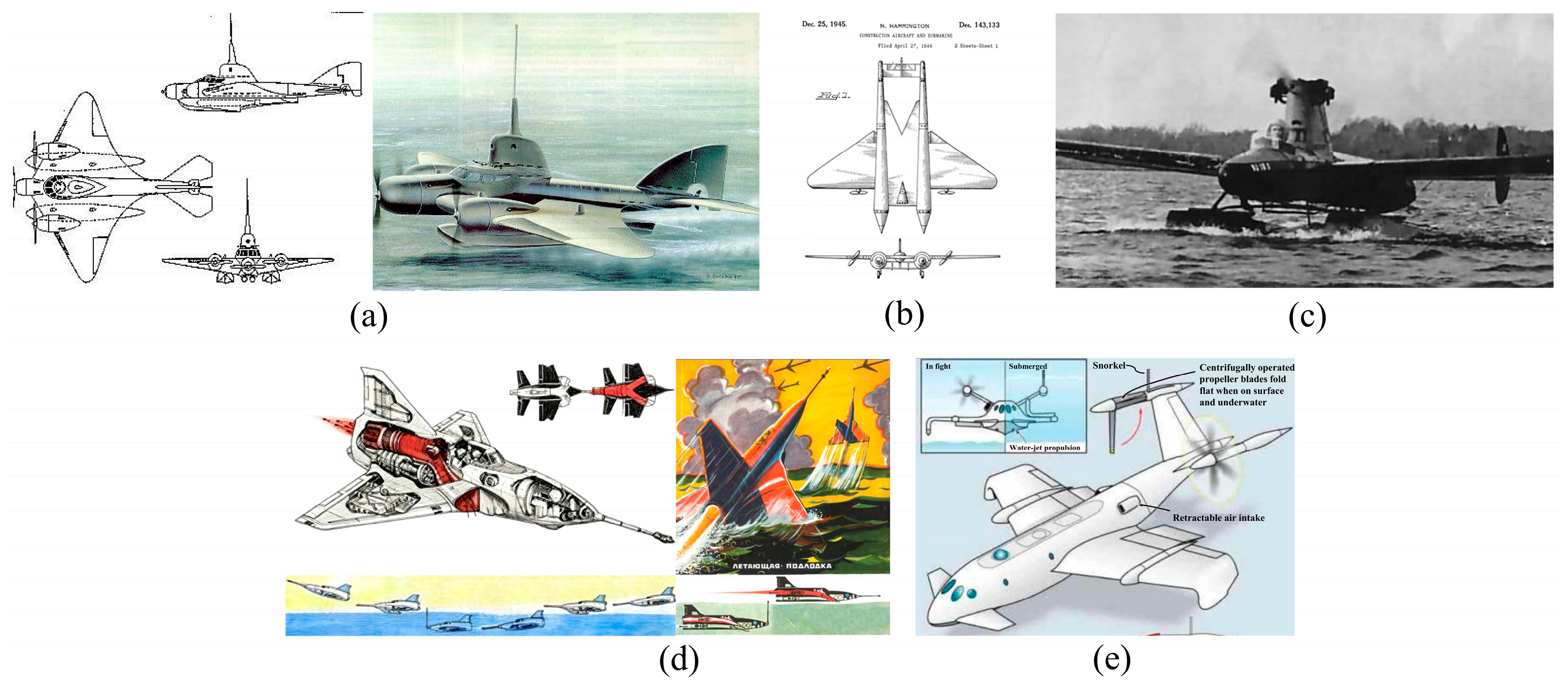
Figure 1. Diving planes. (a) The LPL design; (b) The patent of America; (c) The prototype of Reid; (d) The design of Reid; (e) The designs for large diving planes of America.
Applsci 15 11868 g001
Figure 2. Transformation of UAUV development mode.
Applsci 15 11868 g002
Figure 3. Classification of UAUVs.
Applsci 15 11868 g003
Figure 5. Four shafts with eight rotors and tilt rotors: (a) FURG rotary-wing UAUV with eight rotors in 2018 [72]; (b) Rutgers, The State University of New Jersey rotary-wing UAUV with eight rotors in 2017 [73]; (c) Air Force Engineering University rotary-wing UAUV with eight rotors in 2018 [72]; (d) the National University of Singapore UAUV with tilt rotors in 2020 [72]; (e) Dalian Maritime University UAUV with tilt rotors in 2019 [45].
Applsci 15 11868 g005
Figure 6. Fixed-wing UAUVs: (a) North Carolina State University fixed-wing UAUV in 2017 [72]; (b) Johns Hopkins University fixed-wing UAUV in 2018 [72]; (c) Imperial College London fixed-wing UAUV in 2019 [73]; (d) SJTU fixed-wing UAUV in 2022 [51].
Applsci 15 11868 g006
Figure 7. Folding-wing UAUVs: (a) MIT folding-wing UAUV in 2011 [72]; (b) BUAA bionic folding-wing UAUV in 2014 [72]; (c) MIT folding-wing UAUV in 2012 [72]; (d) BUAA folding-wing UAUV in 2013 [73]; (e) Imperial College London folding-wing UAUV in 2017 [72]; (f) Shape design of Air Force Engineering University high-speed folding-wing UAUV in 2012 [63].
Applsci 15 11868 g007
Figure 8. Hybrid-wing and flapping-wing UAUVs: (a) SJTU hybrid-wing UAUV in 2022 [65]; (b) Harvard University flapping-wing UAUV in 2017 [72].
Applsci 15 11868 g008
Figure 9. Configuration selection.
Applsci 15 11868 g009
Figure 10. Variable buoyancy system.
Applsci 15 11868 g010
Figure 11. Passively flooding and draining wing structures.
Applsci 15 11868 g011
Figure 12. Folding mechanism [60].
Applsci 15 11868 g012
Figure 13. The water-to-air transition modes of UAUVs.
Applsci 15 11868 g013
Figure 14. The air-to-water transition modes of UAUVs.
Applsci 15 11868 g014
Figure 15. Rotor takeoff and landing: (a) The rotor takeoff of the BUAA bionic UAUV [40]; (b) The rotor takeoff and landing of SJTU hybrid-wing UAUV [65].
Applsci 15 11868 g015
Figure 16. The water entry and exit modes of fixed-wing and folding-wing UAUVs: (a) The pull takeoff of SJTU fixed-wing UAUV [51]; (b) The gliding landing of SJTU fixed-wing UAUV [51].
Applsci 15 11868 g016
Figure 17. Buffered and load reduction design.
Applsci 15 11868 g017
Figure 18. Setting of ventilation slot on the wing [138].
Applsci 15 11868 g018
Figure 19. (a) CAD diagram of the developed gearbox [144]; (b) Simplified diagram with colors matched to (a) [144]; (c,d) The two modes of the gearbox [144].
Applsci 15 11868 g019
Figure 20. A hybrid power system for the medium UAUV.
Applsci 15 11868 g020
Figure 21. The integrated observation of ocean and air fronts formed by cold and warm currents and cold and warm air masses.
Applsci 15 11868 g021
Figure 22. The integrated observation of large-scale vortices.
Applsci 15 11868 g022
Figure 23. Applications, and future development trends of UAUVs.
Applsci 15 11868 g023
Table 1. Main parameters and experiments of UAUV prototypes (Part 1). Main parameters and experiments of UAUV prototypes (Part 2).
Part 1
CategoryUAUV PrototypeNameYearDevelopment GroupMain Design ParameterPrototype ExperimentRefs.
Length
(m)
Wing Span (m)Mass
(kg)
Max Velocity
(m/s)
Endurance
(min)
AirUnderwater
Water EntryWater Exit
Rotary
-wing UAUV
Quad rotorsApplsci 15 11868 i001Miniature UAUV2019University of California, Berkeley\\0.2\\Y Y
N Y
[34]
Applsci 15 11868 i002Aerial covert unmanned nautical
system
2016Johns Hopkins University Applied Physics Laboratory\\\\\N N
N N
[35]
Applsci 15 11868 i003Aerial and
underwater vehicle
2021Shanghai Maritime University0.35\2.1\\Y Y
Y Y
[36]
Applsci 15 11868 i004Cormorant2016Georgia Institute of Technology\\\7.6 (air)
1
(underwater)
10 (air)
56
(underwater)
Y Y
Y Y
[37]
Applsci 15 11868 i005Loon Copter2018The University of Auckland0.5\2.70.5
(underwater)
12 (air)
22
(underwater)
Y Y
Y Y
[38]
Applsci 15 11868 i006Nezha-F2023Shanghai Jiao Tong University (SJTU)0.4\1.25\4 (air)
120
(underwater)
Y Y
Y Y
[39]
Applsci 15 11868 i007Aerial-aquatic hitchhiking robot2022BeiHang
University (BUAA)
0.40.130.95\\Y Y
Y Y
[40]
Four shafts with eight rotorsApplsci 15 11868 i008Hybrid UAUV2018Universidade Federal do Rio Grande (FURG)\0.271.45\\N N
N N
[41]
Applsci 15 11868 i009Multirotor aerial-
underwater vehicle
2017Rutgers, The State University of New Jersey\\3.857 (air)
1.1
(underwater)
72 (air)
150
(underwater)
N Y
N N
[42]
Applsci 15 11868 i010UAUV2018Air Force
Engineering University
\\2.57\\N Y
N N
[43]
Tilt
rotors
Applsci 15 11868 i011Morphable aerial-aquatic quadrotor2020National University of
Singapore
0.38\0.505\7(air)Y Y
Y Y
[44]
Applsci 15 11868 i012UAUV2019Dalian
Maritime University
\\1.2\\N N
N N
[45]
Applsci 15 11868 i013Trans-medium hexacopter2020Bauman Moscow State Technical University\\\\\N N
N N
[46]
Fixed-wing UAUVApplsci 15 11868 i014EagleRay2017North
Carolina State University
1.41.55.8122 (air)
0.89
(underwater)
7.43 (air)Y Y
Y Y
[47]
Applsci 15 11868 i015Sherbrooke University water-air
vehicle
2017The University of Sherbrooke\10.58410 (air)\Y Y
Y Y
[48]
Applsci 15 11868 i016Unmanned aerial-aquatic vehicle2018Johns Hopkins University\0.610.2\\Y Y
N Y
[49]
Applsci 15 11868 i017Aerial-aquatic robot2019Imperial College London\\0.1610 (air)\Y Y
N Y
[50]
Applsci 15 11868 i018Diving
beetle—Δ
2022SJTU0.931.2338 (air)
0.89
(underwater)
13.9 (air)
77.6
(underwater)
Y Y
Y Y
[51]
Part 2
CategoryUAUV PrototypeNameYearDevelopment GroupMain Design ParameterPrototype ExperimentRefs.
Length
(m)
Wing Span (m)Mass
(kg)
Max Velocity (m/s)Endurance
(min)
AirUnderwater
Water EntryWater Exit
Folding-wing UAUVApplsci 15 11868 i019Robotic flying fish2011Massachusetts Institute of Technology (MIT)0.250.320.1510 (underwater)\N N
N N
[52]
Applsci 15 11868 i020Hybrid
unmanned air-underwater vehicle
2016U.S. Naval
Research
Laboratory
1.1\7.60.34
(underwater)
\N Y
N N
[53]
Applsci 15 11868 i021Cross-media UAV2019Jilin University0.81.212.9135\N N
N N
[54]
Applsci 15 11868 i022Underwater aerial transmedia vehicle2020Center South University0.6\2.0318 (air)
0.5
(underwater)
10 (air)
10
(underwater)
N N
N N
[55]
Applsci 15 11868 i023Underwater UAV2012Nanchang Hangkong
University
\\7.4330 (air)
1.5
(underwater)
\N Y
N N
[56]
Applsci 15 11868 i024Flying fish2014BUAA1.983.4120.5
(underwater)
\Y Y
Y Y
[57]
Applsci 15 11868 i025Project gannet2012MIT\\\7 (air)\Y Y
Y N
[58]
Applsci 15 11868 i026Submersible UAV2013BUAA2.631.9312.820 (air)
0.5
(underwater)
30 (air)
20
(underwater)
N N
Y N
[59]
Applsci 15 11868 i027Aquatic
micro air
vehicle
2017Imperial
College
London
\0.590.210 (air)14 (air)Y Y
Y N
[60]
Applsci 15 11868 i028Aquatic
micro air vehicle
2017Imperial
College
London
0.520.450.111 (air)\Y Y
N Y
[61]
Applsci 15 11868 i029Dipper2021Swiss Federal Institute of Technology Zurich1.162.13.130.5 (air)
0.83
(underwater)
4 (air)
8
(underwater)
Y Y
Y Y
[62]
Applsci 15 11868 i030High-speed folding-wing UAUV2012Air Force
Engineering University
\\\272(air)\N N
N N
[63]
Hybrid-wing UAUVApplsci 15 11868 i031Hai Kun2017Shenyang
Institute of
Automation
0.711.15120.56
(underwater)
\Y Y
N Y
[64]
Applsci 15 11868 i032Ne Zha2022SJTU0.961.514.6830 (air)
0.3
(underwater)
\Y Y
Y Y
[65]
Flapping-wing UAUVApplsci 15 11868 i033Hybrid aerial-aquatic microrobot2017Harvard
University
\\2 × 10⁻⁴\\Y Y
Y Y
[66]
Applsci 15 11868 i034Dual aerial/aquatic vehicle2015MIT\\0.06\\Y Y
N N
[67]
Table 2. The selection of water entry and exit modes.
Transition modeGliding takeoff
and landing
Rotor takeoff
and landing
Pull takeoff and
swooping landing
UAUV
configuration
Fixed-wing and
folding-wing UAUVs
Rotary-wing and
hybrid-wing UAUVs
Fixed-wing and
folding-wing UAUVs
Angle of attack
during the takeoff
MediumSmallBig
Thrust ratios for the individual propellersLowMediumHigh
TimeLongMediumShort
Impact of the marine environmentStrongMediumMedium
Table 3. Propeller propulsion system.
PropulsionBoth air and underwater propellersOnly air propellersDual purpose propellersDeformable propellers
Aerial performanceGoodExcellentSo-soSo-so
Underwater
performance
ExcellentSo-so (without the transmission devices)
Good (with the transmission devices)
GoodGood
Design key pointsWeight reduction and shape optimizationThe transmission devices to improve the underwater efficiencyPropeller
parameters
Folding or other deformation mechanism
Table 4. Economic factors of UAUVs.
CategoryR&D CostManufacturing CostPractical Deployment BarrierCommercialization Barrier
Rotary-wingLowLow
Low load
Low speed
The dispersion of research forces leads to high research and development costs.
Most of the research and development efforts belong to the academic community, resulting in poor market adaptability.
The dispersion of technological routes leads to low technological maturity.
Facing competition from AUVs and UAVs.
Fixed-wingMediumMedium
High requirements for takeoff and landing platforms (ships and islands)
Folding-wingHighHigh
Hybrid-wingMediumMedium
Heavy weight caused by structural redundancy
Flapping-wingHighHigh
Complex technology
A tiny volume
Disclaimer/Publisher’s Note: The statements, opinions and data contained in all publications are solely those of the individual author(s) and contributor(s) and not of MDPI and/or the editor(s). MDPI and/or the editor(s) disclaim responsibility for any injury to people or property resulting from any ideas, methods, instructions or products referred to in the content.