Abstract
Transient dynamic balancing of flexible rotors is of significant practical value in engineering. Traditional dynamic balancing requires repeated trial weights and start–stop cycles, resulting in inefficient balancing. This paper proposed a multi-layer LSTM (Long Short-Term Memory) network-based method for transient dynamic balancing of flexible rotors. Firstly, a dynamic model of the rotor bearing system is established using the finite element method. Secondly, leveraging the relationship between transient unbalance force and quantity, a formula using the force zero-crossing to identify unbalance magnitude and phase is derived, and a multi-layer LSTM architecture is established to predict the unbalance force from the rotor dynamic response. Finally, a complete transient dynamic balancing solution based on the multi-layer LSTM network is developed. Simulation verification is conducted on a three-disc rotor, and the identification errors of unbalance phase and eccentricity are both less than 5%. After balancing, the maximum amplitude of the rotor decreases by about 93%. Additional verification is carried out on the rotor test rig. The experimental results show that the multi-layer LSTM flexible rotor transient dynamic balancing method can significantly reduce unbalance vibration: the transient amplitude of the rotor decreases by 70.22%, and the steady-state amplitude decreases by 69.3% after balancing.
1. Introduction
Modern rotating machinery, particularly aero-engine rotor systems, are evolving toward higher aspect ratios, extreme rotational speeds, and increased load capacities [1,2,3]. However, manufacturing and assembly processes inevitably introduce mass imbalance, which induces significant vibration during operation. At high speeds, even minor imbalances can lead to severe consequences such as rotor deformation, rotor–stator rub, or bearing failure [4,5]. Therefore, precise dynamic balancing is essential for safe operation of high-speed flexible rotors [6].
Rotor dynamic balancing technology has evolved into two primary methodologies through long-term development: the influence coefficient method and modal balancing method [7,8]. Both conventional balancing methods have achieved theoretical maturity, yet each demonstrates distinct advantages and limitations in practical applications [9,10]. To address these limitations, researchers have continuously pursued methodological innovations. Zhou et al. [11] developed an AMB-based online compensation algorithm combining LMS and ICM for real-time vibration control during operation. Guan et al. [12] proposed an adaptive notch filter and influence coefficient method to reduce mass imbalance vibration in active magnetic bearing rotors, validated experimentally. Yuan et al. [13] optimized the eccentric wheel mass distribution using ADAMS simulation to reduce vibration and improve stability in scroll compressors. Zhang et al. [14] developed a compact pneumatic dual-plane balancing system that achieves high-precision online vibration control for machine tools. Stoesslein et al. [15] introduced a laser dynamic balancing technology utilizing influence coefficient-controlled ablation for online rotor correction. Deepthikumar et al. [16] developed a transfer matrix method for single-run subcritical balancing of rotors with unbalance–bow coupling, experimentally validated. All methods exhibit distinct characteristics: the influence coefficient method offers operational simplicity but requires iterative start–stop cycles, while modal balancing delivers higher precision yet depends critically on accurate rotor modal parameters.
Building upon this foundation, researchers have explored various dynamic balancing methodologies to enhance both operational efficiency and precision. Chen et al. [17] proposed a genetic algorithm-based method to optimize multi-stage rotor assembly and reduce unbalance. Zou et al. [18] developed a model-based online balancing method using AKF to achieve real-time unbalance identification without trial weights while compensating for system errors. Zhao’s method enables ICM-accurate, trial-weight-free balancing via transient vibration analysis [19,20,21,22]. Through integrating modal theory, signal processing techniques, intelligent algorithms, and finite element modeling, researchers have developed numerous enhanced methods. Notably, transient dynamic balancing has emerged as a particularly promising approach that utilizes acceleration-phase vibration responses, demonstrating significant improvements in both efficiency and operational safety while showing substantial potential for industrial applications.
Neural network technology has demonstrated exceptional applicability in rotor dynamic balancing applications due to its superior nonlinear mapping capabilities and automated feature extraction from operational data. Gohari, Walker, and Tselios [23,24,25] proposed an intelligent unbalance identification method using vibration time–frequency features through neural networks, validating AI’s effectiveness in rotor monitoring. Wang et al. [26] developed an enhanced balancing method for dual-rotor systems, effectively addressing complex vibrations from anisotropic supports and rotor coupling. Cao et al. [27] developed an LSTM-based method for multi-speed unbalance identification, effectively handling complex vibration transmission dynamics. Zhang et al. [28] developed a trial-weight-free, two-stage deep learning balancing method trained on single-run data, validated numerically and experimentally. Li et al. [29] developed a trial-weight-free rotor balancing method using unsupervised deep learning, achieving cost-effective performance comparable to conventional approaches. Zhong et al. [30] developed an unsupervised deep Lagrangian network for trial-weight-free rotor balancing, leveraging physical priors to achieve cost-effective and accurate performance.
Furthermore, neural networks have extensive applications in rotor dynamics beyond unbalance identification. Pavlenko et al. [31] combined finite element modeling with an artificial neural network to determine the relationship between bearing stiffness and rotor speed. Sun et al. [32] developed a spatio-temporal deep learning model using PMU data to accurately predict rotor angle stability with strong transfer learning capability. Yang et al. [33,34] proposed a noise-resistant deep dilated CNN method for robust dynamic load identification under varying conditions. Yang et al. [35,36] established a neural network interpretability framework, proving RNN’s dominance in load identification via spectral/temporal analysis. Neural networks exhibit considerable promise for intelligent fault detection in rotor systems, notwithstanding their dependence on high-quality training datasets and inherent limitations in model interpretability.
Existing rotor balancing methods have inherent limitations: the influence coefficient method requires multiple trial runs, and modal balancing involves complex procedures. While transient characteristic-based methods eliminate the need for trial weights and improve efficiency by utilizing transient responses, current implementations that rely on dynamic load identification suffer from computational complexity and high noise sensitivity. LSTM networks excel at rotor vibration analysis by capturing temporal patterns and speed-adaptive features, achieving high-precision unbalance force identification through a black-box direct mapping approach without requiring manually designed CNN-style filter banks or RNN-based keyphasor signal pre-alignment. Their robustness and processing efficiency make them ideal for transient balancing of flexible rotors, delivering both rapid analysis and high-fidelity results.
This paper proposes a transient balancing method for flexible rotors based on a multi-layer LSTM network. First, the dynamic equations of the flexible rotor system are established to provide a theoretical foundation for developing transient balancing methods. Subsequently, analytical expressions are derived to determine both the magnitude and phase of unbalance through identification of zero-crossing points in transient unbalance force, and a multi-layer LSTM neural network architecture is constructed. The dynamic balancing process for flexible rotors employing the multi-layer LSTM network is then elaborated. Finally, the effectiveness of the proposed method is verified through numerical simulations assess the LSTM network’s predictive capability for transient unbalance force, while the accuracy of unbalance calculations based on transient force is analyzed, and experimental validation is conducted on a rotor test rig to demonstrate the efficacy of the LSTM-based transient balancing approach.
2. Dynamic Modeling of Three-Disk Rotor System with Unbalance
The rotor system comprises three rigid disks of specified masses, a rotating shaft, bearings, and support structures. The system dynamics are modeled using the finite element method (FEM), which requires meticulous element discretization and constraint definition, making it particularly suitable for modeling complex rotor configurations.
The rotor is discretized into N nodes connected by N-1 elements. Each shaft segment is modeled as a Timoshenko beam element, accounting for shear deformation and rotary inertia effects. Axial displacement and torsional rotation are neglected at each node, with the model primarily considering the remaining four degrees of freedom: translational displacements along the x- and y-axes and rotational displacements about the x- and y-axes (denoted as x, y, θxi, and θyi, respectively), as illustrated in Figure 1. The material is assumed to be isotropic and homogeneous, operating within the linear elastic range, while the system exhibits linear damping characteristics.
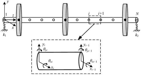
Figure 1.
Schematic diagram of axis unit.
The unbalance response originates from eccentric mass distribution. Based on classical beam theory, the governing differential equations of motion are derived for each shaft element and subsequently assembled into the global system equation:
where M is the mass matrix, C(t) = C + ωG, and includes the damping matrix and the antisymmetric gyroscopic matrix; K(t) is the stiffness matrix of the rotor system; ω is the rotational speed; F(t) is the unbalance force vector; and U(t), , and are, respectively, the displacement, velocity, and acceleration vectors. The system matrices—mass, damping, and stiffness—are square matrices of order 4N × 4N, while the displacement, velocity, acceleration, and unbalance force vectors are column matrices of dimension 4N × 1.
During rotor acceleration, the unbalance force comprises two components: centrifugal force generated by eccentric mass and tangential inertial force induced by angular acceleration. The rotor system’s displacement response and corresponding unbalance force can be expressed, respectively, as
where
In the governing equations, Fxi(t) and Fyi(t) denote the instantaneous unbalance force components along the x- and y-directions, respectively, acting on the i-th node of the rotor system, where i represents the node number, mi represents the imbalance mass at the node, ei is the eccentricity and represents the distance from the center of the disc mass to the center of the rotation axis, ω represents the rotational speed, a represents the angular acceleration, φ(t) represents the rotation angle of the rotor at time t, and φei represents the phase angle of the unbalance mass.
3. A Multi-Layer LSTM Network Balancing Method
3.1. Unbalance Force and Unbalance Magnitude
Based on the dynamic analysis of rotor acceleration and the auxiliary angle transformation, the unbalance force components in Equations (4) and (5) can be reformulated as
where
From Equations (6) and (7), the unbalance force is shown to be the product of eccentricity, squared rotational velocity, and acceleration terms with trigonometric components. This formulation causes periodic nullification of the horizontal unbalance force component (Fxi = 0) at specific instants, during which the tangential and normal forces exhibit equal magnitudes but opposite directional components in either horizontal or vertical orientation, as illustrated in Figure 2. The figure depicts positions A1 and A2 representing the rotor’s mass center at consecutive moments when the horizontal unbalance force vanishes, demonstrating the dynamic equilibrium condition where opposing force components cancel in the x-direction.
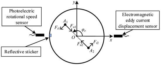
Figure 2.
Schematic diagram of the moment when the horizontal transient unbalance force is equal to 0.
The experimental setup employs an eddy current displacement sensor to measure rotor vibration responses. Reflective markers are precisely mounted on the turntable’s outer circumference, enabling rotational speed measurement through pulse signals acquired by a photoelectric tachometer during each complete revolution. Prior to operation, the reflective markers must be aligned adjacent to the photoelectric sensor, with the initial pulse signal serving as the angular reference position for rotational phase determination.
At a specific moment, the components of the tangential and normal forces along the x-axis cancel each other out. This instant is selected as the calculation reference point, where Fxi(t) = 0. From Equation (6), the following condition holds at this point:
Here, k denotes the index of the k-th computational reference point (k ∈ [1, n]), where n represents the total number of such reference points. The unbalance phase angle can be derived from Equation (11) as
To enhance the phase angle estimation accuracy, the final value is obtained by averaging the computed phase angles across all reference points on the unbalance force profile.
Following the determination of the unbalance phase angle, the magnitude of the mass unbalance (Um) can be computed using
Dynamic balance correction is achieved by either adding counterweights or removing mass at the calculated angular positions on corresponding planes, based on the determined unbalance phase angle and magnitude.
3.2. Unbalance Force Identification
As established in Section 3.1, rotor unbalance can be precisely located and quantified through transient force analysis, with the key challenge being accurate transient force acquisition in rotating systems.
To circumvent errors from model uncertainties, a neural network surrogate model is trained on rotor input-output data, transforming the dynamic system into an identification problem for accurate force computation.
The LSTM-based surrogate model establishes an accurate mapping between rotor dynamics and unbalance forces. Trained on paired transient response–unbalance force data, it learns multi-scale temporal dependencies to solve this complex multi-variable regression problem. As shown in Figure 3, the architecture processes standardized displacement inputs through stacked LSTM layers for temporal pattern extraction, followed by hidden layers for feature abstraction and fully connected layers that predict correction-plane unbalance forces.
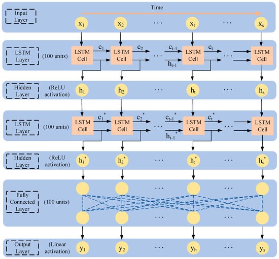
Figure 3.
Schematic diagram of multi-layer LSTM neural network structure.
The Rectified Linear Unit (ReLU) is adopted for hidden layers due to its computational efficiency, non-vanishing gradients, and inherent regularization via sparsity. Its non-saturating nature outperforms sigmoidal functions in convergence speed and generalization.
The design incorporates 20-rate dropout layers and optimized time-windowing to process three-dimensional data. LSTM’s gating mechanism preserves long-term dependencies while hierarchically extracting multi-scale features, forming an end-to-end rotor vibration-to-force mapping system.
The LSTM’s training process demands careful tuning of hyperparameters to balance convergence, stability, and computational efficiency while maintaining model performance.
The model architecture primarily consists of two stacked LSTM layers followed by two fully connected (Dense) layers. Each LSTM layer contains 100 hidden units, with hidden layers utilizing the ReLU activation function and the output layer employing a linear activation function. The model was trained with a batch size of 50 using the Adam optimizer at a learning rate of 0.001.
3.3. Dynamic Balance Procedure
The proposed multi-layer LSTM-based rotor dynamic balancing methodology comprises five key implementation phases: dataset generation, data preprocessing, network architecture development and training, unbalance quantification, and experimental validation of rotor balancing. Figure 4 illustrates the complete workflow, while the technical implementation proceeds through the following sequence of operations:
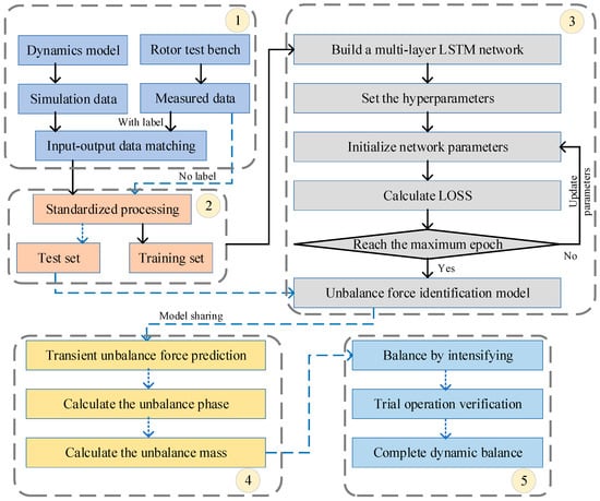
Figure 4.
Flowchart of rotor dynamic balancing implementation based on multi-layer LSTM network.
(1) The dataset integrates computational modeling and experimental data, containing labeled input–output pairs of transient vibration responses and their corresponding unbalance forces.
(2) The vibration data and imbalance parameters are preprocessed for LSTM training, including sampling, normalization, and reshaping into 3D tensors. The dataset is divided into labeled samples for training and unlabeled samples for unbalance forces prediction.
(3) A multi-layer LSTM network models the relationship between unbalance forces and parameters. The model undergoes initial training with parameter optimization through loss minimization, followed by hyperparameter tuning. The best-performing model is saved and validated on the test set for imbalance force prediction.
(4) The trained model predicts transient unbalance forces from test data under unknown conditions, then computes the required correction masses and angles per Section 3.1 Methodology.
(5) The verification process applies counterweights based on the identified unbalance parameters and validates the results. If vibration levels meet specifications, balancing is complete. Otherwise, the system iteratively optimizes network parameters and updates test data until all thresholds are satisfied.
4. Simulation and Experimental Verification
A comprehensive validation of the proposed method is conducted through both numerical simulations and experimental tests on a three-disk rotor system. The validation process comprises three main stages: characterization of the rotor system’s key physical parameters, numerical verification of the unbalance identification accuracy, and experimental evaluation of dynamic balancing performance using actual vibration measurements from the test rig.
4.1. Simulation Verification of the Three-Disc Rotor
To validate the proposed methodology, a finite element model of the three-disk rotor system is developed as illustrated in Figure 5, comprising the shaft, disks, and bearing supports. The rotor is discretized into 26 Timoshenko beam elements connecting 27 nodes, with key material and geometric parameters detailed in Table 1. Transient dynamic simulations are performed to generate the rotor’s vibration response under unbalance excitation. The multi-layer LSTM-based balancing algorithm is then applied to these simulated responses, demonstrating its effectiveness in identifying and correcting unbalance conditions.
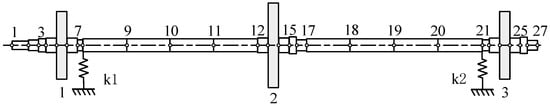
Figure 5.
Finite element node division of three-disc rotor.

Table 1.
Parameters of rotor finite element model.
Predicting rotor unbalance forces from vibration responses using neural networks requires extensive training data. The prediction accuracy improves with increasing training samples as the network learns more comprehensive feature representations. In the rotor system dynamic simulations, vibration responses and corresponding unbalance forces are obtained by introducing various eccentric mass configurations at different positions on the central disk. The investigation further accounts for coupling effects from potential unbalance conditions on both side disks, ultimately generating 120 complete datasets through this systematic parameter variation.
The experimental data undergo standardized preprocessing before being divided into training and testing sets following an 8:2 ratio. The processed datasets are then utilized to train the specifically designed network architecture, establishing accurate mapping between vibration characteristics and unbalance force parameters.
The loss function quantifies the error between predicted and expected outputs, where smaller values indicate better network prediction performance. During training, each iteration calculates the loss function across all samples and adjusts the network’s weights and biases according to the optimizer settings to minimize this loss. The training loss curve shown in Figure 6 demonstrates favorable model performance, with the loss decreasing to near-zero levels and converging steadily on both training and test datasets.
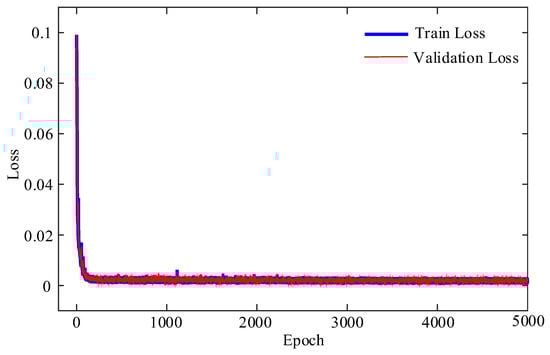
Figure 6.
Loss curve of the multi-layer LSTM network.
The identification process examines an initial imbalance of 4.6 × 10⁻⁴ kg·m at the 45° position on the central disk. Figure 7 shows the rotor system’s transient response during a 4 s acceleration period and the corresponding unbalance force. To enhance identification accuracy, the vibration response is preprocessed by selecting data from the first 2.8 s, representing approximately 50% of the maximum amplitude.
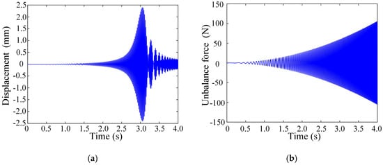
Figure 7.
Transient response and unbalance force of rotor. (a) Horizontal vibration displacement. (b) Horizontal unbalance force.
Figure 8 compares the network-identified unbalance force with theoretical values. To calculate the unbalance parameters, the initial unstable vibration displacement data are discarded, and only the stabilized unbalance force data from the 0.8 s to 2.8 s interval are utilized. This approach accounts for the potential instability of acceleration during the initial startup phase under practical conditions. The imbalance calculation in Figure 9 employs sampled averaging of the unbalance force curve. To mitigate significant errors that occur when sampling near zero-crossing points, a 20% threshold is applied to exclude outliers before averaging the remaining values. This approach enhances calculation accuracy. The identified imbalance measures 4.464 × 10⁻⁴ kg·m at 47.58° according to Equations (12)–(14). Balancing is achieved by adding an eccentric mass at the 227.58° position. The vibration signal’s envelope is extracted using Hilbert transform to obtain the amplitude curve. Figure 10 demonstrates the vibration response comparison before and after dynamic balance correction. As seen in the figure, the rotor reaches its critical speed of 3495 rpm after 3.05 s, where the vibration amplitude peaks at 2.407 mm. After balancing, the maximum amplitude is reduced to 0.162 mm, representing a 93% reduction.
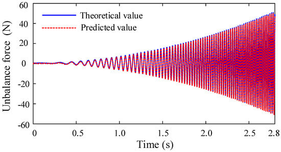
Figure 8.
Unbalance force predicted by simulation response.
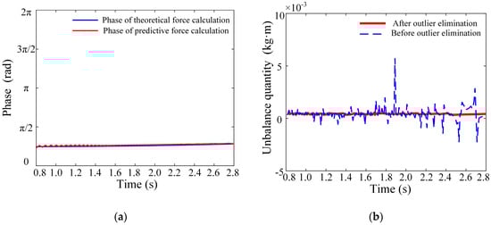
Figure 9.
Unbalance recognition results: (a) Identification results of unbalanced phase angle. (b) Identification results of eccentricity.
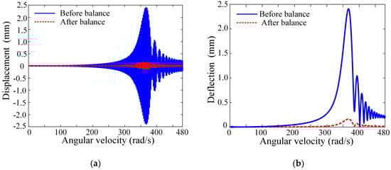
Figure 10.
Comparison of response before and after balancing: (a) Vibration response comparison. (b) Amplitude comparison.
The method’s effectiveness is verified through simulations of a turntable with varying imbalance magnitudes and angular positions. Table 2 presents the identified imbalance and phase angle results, with the phase angle relative error calculated according to Equation (15).
Table 2.
Identification results of unbalance quantity.
The results in the table demonstrate relative errors below 5% for both unbalance phase and eccentricity identification across all test cases, confirming the method’s high accuracy in rotor unbalance detection.
4.2. Experimental Verification
Experimental verification of the proposed dynamic balancing method is conducted using a three-disk rotor test system. The test rig configuration shown in Figure 11 comprises a rigid base, three-disk rotor assembly, bearing supports, flexible coupling, servo motor, eddy current displacement sensors, photoelectric tachometer, and data acquisition system. The rotor’s physical parameters match the simulation specifications, with sensor models and technical parameters detailed in Table 3.
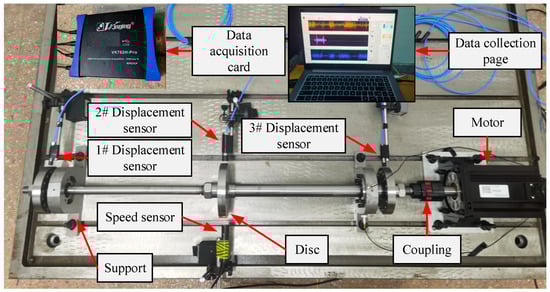
Figure 11.
Rotor test rig.
Table 3.
Sensor model and parameters.
The experimental setup simulates imbalance masses by installing different-sized bolts on the turntable mounting holes. A reflective marker at the 0° position enables rotor position tracking through the photoelectric tachometer, with the initial pulse signal marking the operation start time. The eddy current sensor monitors horizontal vibration responses throughout the test.
For a representative case with 1.179 × 10⁻³ kg·m imbalance at 45° (achieved by a 19.657 g bolt at 60 mm eccentricity), the motor drives the rotor at 105 rad/s2 angular acceleration for 5 s. The data acquisition system operates at 12 kHz sampling frequency, capturing the vibration response shown in Figure 12. The vibration peak reaches 2.535 mm at 3.2 s (approximately 3200 rpm), while the key signal intervals decrease progressively with increasing rotational speed.
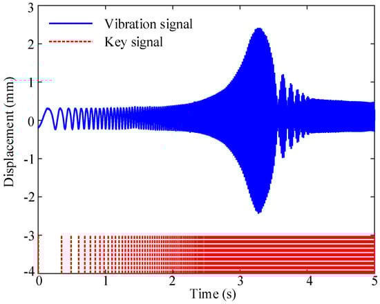
Figure 12.
Horizontal vibration displacement.
The vibration response data undergo preprocessing to enhance neural network prediction accuracy. Only response segments with amplitudes below 50% of the maximum value are fed into the trained network model. The analysis selects vibration signals within the initial 2.8 s interval from the measured horizontal displacement data for unbalance force identification, with results presented in Figure 13.
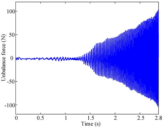
Figure 13.
Unbalance force predicted from experimental response.
The unbalance force prediction results in Figure 13 demonstrate improved parameter calculation accuracy after removing unstable early-stage acceleration data. Analysis of the remaining stable data yields an unbalance quantity of 1.129 × 10⁻³ kg·m at 41.55°, with relative errors of 0.96% for phase angle and 4.24% for mass identification.
Dynamic balance correction is performed by adding counterweights opposite the identified unbalance position. The rotor subsequently accelerates at 105 rad/s2 for 5 s, with the transient vibration characteristics before and after balancing shown in Figure 14. For the same unbalance condition, the influence coefficient method identified an unbalance of 1.134 × 10⁻³ kg·m at 40.67°, with relative errors of 1.20% for phase angle and 3.82% for mass identification. The transient vibration responses before and after balancing using the influence coefficient method are shown in Figure 15, where the maximum amplitude decreases from 2.535 mm to 0.840 mm, representing a 66.86% reduction. Upon reaching 5000 RPM, the steady-state vibration displacement comparison is shown in Figure 16, with the corresponding frequency–domain plot presented in Figure 17. The dominant 83.5 Hz component, corresponding to the characteristic frequency of rotor unbalance, exhibits a significant amplitude reduction from 0.363 mm to 0.111 mm—a 69.4% decrease in vibration level. The results show significant vibration reduction after balancing: Transient response amplitude decreases from 2.535 mm to 0.755 mm (70.22% reduction). Steady-state amplitude at 5000 rpm reduces from 0.456 mm to 0.140 mm (69.3% reduction). These measurements confirm the method’s effectiveness in substantially reducing both transient and steady-state vibration levels through dynamic balancing.
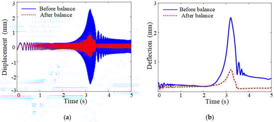
Figure 14.
Comparison of transient response of rotor before and after balancing: (a) Vibration response comparison. (b) Amplitude comparison.
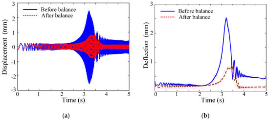
Figure 15.
Transient response comparison before and after ICM balancing: (a) Vibration response comparison. (b) Amplitude comparison.
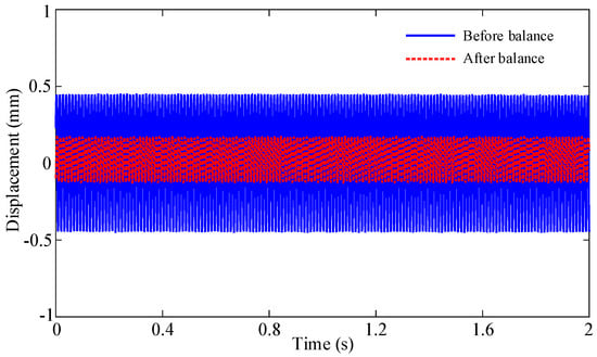
Figure 16.
Comparison of steady-state response of rotor before and after balancing.
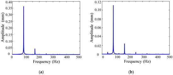
Figure 17.
Vibration response before and after balancing at 5000 rpm. (a) Before balancing. (b) After balancing.
The method’s effectiveness is further verified through experimental tests applying various counterweights at different angular positions on the turntable. Table 4 presents the identified unbalance parameters, with phase angle relative errors calculated according to Equation (15).
Table 4.
Identification results of unbalance parameters in experimental samples.
The test results in the table demonstrate relative errors below 10% for all identified imbalance parameters, confirming the method’s effectiveness in rotor dynamic balancing applications.
5. Conclusions
This paper presents a multi-layer LSTM network-based method for dynamic balancing of flexible rotors. The approach first establishes a rotor dynamic model using the finite element method and then analyzes the transient dynamic characteristics of eccentric rotors while constructing a multi-layer LSTM neural network to predict unbalance forces for calculating both unbalance magnitude and phase. Numerical simulations demonstrate the method’s effectiveness with less than 5% relative error in unbalance identification and approximately 93% reduction in maximum vibration amplitude after balancing. Experimental verification shows comparable performance, with unbalance identification errors below 10% and vibration amplitude reductions of about 70.22% following balancing correction. The study provides a novel solution framework for transient dynamic balancing of flexible rotors in engineering applications. Although the method relies on high-quality training data and exhibits limited model interpretability, it demonstrates promising potential for online balancing of high-speed rotating machinery (such as aero-engines) and intelligent fault early-warning systems. By integrating the accuracy of numerical modeling with experimental validation, this research establishes a new methodological framework for transient dynamic balancing in practical engineering scenarios. The balancing method presented in this study has been experimentally validated on a single three-disc rotor system. Theoretically, the approach is applicable to multi-rotor systems and more complex operational scenarios, though further investigation is required for such extensions.
Author Contributions
Q.L., conceptualization, methodology, investigation, data curation, writing—original draft, visualization, and funding acquisition; W.M., resources, conceptualization, methodology, formal analysis, and investigation; Y.T., resources, writing—review and editing, and data curation; Z.T., resources, writing—review and editing, and data curation; M.Z., validation, resources, and writing—review and editing; C.Z., validation, resources, and writing—review and editing; X.M., validation, resources, and writing—review and editing; D.J., conceptualization, resources, writing—review and editing, formal analysis, validation, supervision, and funding acquisition. All authors have read and agreed to the published version of the manuscript.
Funding
This research was funded by the National Natural Science Foundation of China, grant number 12502011, 52572412.
Institutional Review Board Statement
Not applicable.
Informed Consent Statement
Not applicable.
Data Availability Statement
The original contributions presented in the study are included in the article, further inquiries can be directed to the corresponding author.
Conflicts of Interest
The authors declare no conflicts of interest.
References
- Ma, P.P.; Zhai, J.Y.; Wang, Z.H.M.; Zhang, H.; Han, Q.K. Unbalance Vibration Characteristics and Sensitivity Analysis of the Dual-Rotor System in Aeroengines. J. Aerosp. Eng. 2021, 34, 04020094. [Google Scholar] [CrossRef]
- Li, W.B.; Wang, W.M.; Zhang, S.; Wang, J.L.; Lin, Y.L.; Li, T.Q. A novel rotor dynamic balancing method based on blade tip clearance measurement without the once per revolution sensor. Chin. J. Aeronaut. 2025, 38, 102975. [Google Scholar] [CrossRef]
- Li, K.X.; Peng, C.; Deng, Z.Q.; Huang, W.; Zhang, Z.M. Field dynamic balancing for active magnetic bearings supporting rigid rotor shaft based on extended state observer. Mech. Syst. Signal Process. 2021, 158, 107801. [Google Scholar] [CrossRef]
- Alves, D.S.; Machado, T.H.; Cavalca, K.L.; Bachschmid, N. Characteristics of oil film nonlinearity in bearings and its effects in rotor balancing. J. Sound Vib. 2019, 459, 114854. [Google Scholar] [CrossRef]
- Puerto-Santana, C.; Ocampo-Martinez, C.; Diaz-Rozo, J. Mechanical rotor unbalance monitoring based on system identification and signal processing approaches. J. Sound Vib. 2022, 541, 117313. [Google Scholar] [CrossRef]
- Bin, G.F.; Li, X.J.; Wu, J.G.; Gao, J.J. Virtual dynamic balancing method without trial weights for multi-rotor series shafting based on finite element model analysis. J. Renew. Sustain. Energy 2014, 6, 042014. [Google Scholar] [CrossRef]
- Goodman, T.P. A least-squares method for computing balance corrections. J. Manuf. Sci. Eng. 1964, 86, 273–277. [Google Scholar] [CrossRef]
- Bishop, R.E.D.; Gladwell, G.M.L. The vibration and balancing of an unbalanced flexible rotor. J. Mech. Eng. Sci. 1959, 1, 66–77. [Google Scholar] [CrossRef]
- Li, L.Q.; Cao, S.Q.; Li, J.; Nie, R.M.; Hou, L.L. Review of Rotor Balancing Methods. Machines 2021, 9, 89. [Google Scholar] [CrossRef]
- Liu, Q.; Xu, X.; Lu, Z.; Yu, L.; Jiang, D. Weak signal extraction of micro-motor rotor unbalance based on all-phase fast Fourier transform. Int. J. Mech. Syst. Dyn. 2024, 4, 202–212. [Google Scholar] [CrossRef]
- Zhou, J.; Wu, H.C.; Wang, W.Y.; Yang, K.Z.; Hu, Y.F.; Guo, X.H.; Song, C.S. Online unbalance compensation of a maglev rotor with two active magnetic bearings based on the LMS algorithm and the influence coefficient method. Mech. Syst. Signal Process. 2022, 166, 108460. [Google Scholar] [CrossRef]
- Guan, X.D.; Peng, H.; Li, H.; Zhang, J.J. Dynamic Balance Correction of Active Magnetic Bearing Rotor Based on Adaptive Notch Filter and Influence Coefficient Method. Appl. Sci. 2025, 15, 4147. [Google Scholar] [CrossRef]
- Yuan, M.L.; Yang, B.; Li, X.; Li, A.N.; Gao, F.; Ge, M.Q. Dynamic Balance Simulation and Optimization of Electric Vehicle Scroll Compressor Rotor System. Appl. Sci. 2024, 14, 5024. [Google Scholar] [CrossRef]
- Zhang, S.H.; Zhang, Z.M. A method to select correcting faces of a double-face dynamic balancing rotor. Adv. Mech. Eng. 2016, 8, 1687814016682892. [Google Scholar] [CrossRef]
- Stoesslein, M.; Axinte, D.A.; Guillerna, A.B. Pulsed laser ablation as a tool for in-situ balancing of rotating parts. Mechatronics 2016, 38, 54–67. [Google Scholar] [CrossRef]
- Deepthikumar, M.B.; Sekhar, A.S.; Srikanthan, M.R. Balancing of flexible rotor with bow using transfer matrix method. J. Vib. Control 2014, 20, 225–240. [Google Scholar] [CrossRef]
- Chen, Y.; Cui, J.W.; Sun, X. An Unbalance Optimization Method for a Multi-Stage Rotor Based on an Assembly Error Propagation Model. Appl. Sci. 2021, 11, 887. [Google Scholar] [CrossRef]
- Zou, D.L.; Zhao, H.; Liu, G.Y.; Ta, N.; Rao, Z.S. Application of augmented Kalman filter to identify unbalance load of rotor-bearing system: Theory and experiment. J. Sound. Vib. 2019, 463, 114972. [Google Scholar] [CrossRef]
- Fu, C.; Xu, Y.D.; Yang, Y.F.; Lu, K.; Gu, F.S.; Ball, A. Response analysis of an accelerating unbalanced rotating system with both random and interval variables. J. Sound Vib. 2020, 466, 115047. [Google Scholar] [CrossRef]
- Zhao, S.B.; Ren, X.M.; Deng, W.Q.; Lu, K.; Yang, Y.F.; Fu, C. A transient characteristic-based balancing method of rotor system without trail weights. Mech. Syst. Signal Process. 2021, 148, 107117. [Google Scholar] [CrossRef]
- Zhao, S.B.; Ren, X.M.; Zheng, Q.Y.; Lu, K.; Fu, C.; Yang, Y.F. Transient dynamic balancing of the rotor system with uncertainty. Mech. Syst. Signal Process. 2022, 171, 108894. [Google Scholar] [CrossRef]
- Zhao, S.B.; Ren, X.M.; Deng, W.Q.; Lu, K.; Yang, Y.F.; Li, L.H.; Fu, C. A novel transient balancing technology of the rotor system based on multi modal analysis and feature points selection. J. Sound Vib. 2021, 510, 116321. [Google Scholar] [CrossRef]
- Gohari, M.; Kord, A.; Jalali, H. Unbalance Rotor Parameters Detection Based on Artificial Neural Network: Development of Test Rig. J. Vib. Eng. Technol. 2022, 10, 3147–3155. [Google Scholar] [CrossRef]
- Walker, R.B.; Vayanat, R.; Perinpanayagam, S.; Jennions, I.K. Unbalance localization through machine nonlinearities using an artificial neural network approach. Mech. Mach. Theory 2014, 75, 54–66. [Google Scholar] [CrossRef]
- Tselios, I.; Nikolakopoulos, P.G. Integrated Artificial Intelligent and Physics-Based Models for Unbalance Estimation in Rotating Systems. J. Vib. Eng. Technol. 2025, 13, 31. [Google Scholar] [CrossRef]
- Wang, D.H.; Chen, L.F.; Long, Y.D.; Bao, R.; Sun, Y.B. HLSM-MIPV Algorithm of unbalance vibration suppression of dual-rotor in contra-rotating propfan. J. Sound Vib. 2025, 595, 118761. [Google Scholar] [CrossRef]
- Cao, Y.M.; Shi, C.Z.; Li, X.J.; Li, M.F.; Bian, J. Unbalanced Position Recognition of Rotor Systems Based on Long and Short-Term Memory Neural Networks. Machines 2024, 12, 865. [Google Scholar] [CrossRef]
- Zhong, S.; Han, H.X.; Hou, L. A two-stage deep-learning-based balancing method for rotating machinery. Meas. Sci. Technol. 2023, 34, 045903. [Google Scholar] [CrossRef]
- Li, L.Q.; Zhong, S.; Chen, H.Z.; Lu, Z.Y. On experiments of a novel unsupervised deep learning based rotor balancing method. Meas. Control 2022, 55, 729–737. [Google Scholar] [CrossRef]
- Zhong, S.; Hou, L. Numerical and experimental studies on unsupervised deep Lagrangian learning based rotor balancing method. Sci. China Technol. Sci. 2023, 66, 1050–1061. [Google Scholar] [CrossRef]
- Pavlenko, I.; Simonovskiy, V.; Ivanov, V.; Zajac, J.; Pitel, J. Application of Artificial Neural Network for Identification of Bearing Stiffness Characteristics in Rotor Dynamics Analysis. Adv. Des. Simul. Manuf. 2019, 325–335. [Google Scholar] [CrossRef]
- Sun, P.Y.; Huo, L.; Chen, X.; Liang, S.Y. Rotor Angle Stability Prediction Using Temporal and Topological Embedding Deep Neural Network Based on Grid-Informed Adjacency Matrix. J. Mod. Power Syst. Clean. Energy 2024, 12, 695–706. [Google Scholar] [CrossRef]
- Yang, H.J.; Jiang, J.H.; Chen, G.P.; Zhao, J.M. Dynamic load identification based on deep convolution neural network. Mech. Syst. Signal Process. 2023, 185, 109757. [Google Scholar] [CrossRef]
- Wang, J.; Song, S.W.; Liu, C.; Zhao, Y.L. Dynamic Load Identification of Thin-Walled Cabin Based on CNN-LSTM-SA Neural Network. Materials 2025, 18, 1255. [Google Scholar] [CrossRef] [PubMed]
- Yang, F.F.; Luo, Y.J.; Du, L.F.; Zhang, Y.H.; Xie, S.L. Study on interpretability of artificial neural network models for dynamic load identification. Measurement 2025, 251, 117210. [Google Scholar] [CrossRef]
- Zhou, J.M.; Dong, L.L.; Guan, W.; Yan, J. Impact load identification of nonlinear structures using deep Recurrent Neural Network. Mech. Syst. Signal Process. 2019, 133, 106292. [Google Scholar] [CrossRef]
Disclaimer/Publisher’s Note: The statements, opinions and data contained in all publications are solely those of the individual author(s) and contributor(s) and not of MDPI and/or the editor(s). MDPI and/or the editor(s) disclaim responsibility for any injury to people or property resulting from any ideas, methods, instructions or products referred to in the content. |
© 2025 by the authors. Licensee MDPI, Basel, Switzerland. This article is an open access article distributed under the terms and conditions of the Creative Commons Attribution (CC BY) license (https://creativecommons.org/licenses/by/4.0/).