Abstract
The aim of this study is to develop the next-generation fully autonomous electric wheelchair capable of operating in diverse environments. This study proposes a self-controlled autonomous mobility system that integrates a monocular camera and laser-based 3D spatial recognition, convolutional neural network-based obstacle recognition, shape measurement, and stair structure recognition technology. Obstacle recognition and shape measurement are performed by analyzing the surrounding space using convolutional neural networks and distance calculation methods based on laser measurements. The stair structure recognition technology utilizes the stair-step characteristics from the laser’s irradiation pattern, enabling detection of distance information not captured by the camera. A principal analysis and algorithm development were conducted using a small-scale autonomous mobility system, and its feasibility was determined by application to an omnidirectional self-controlled autonomous electric wheelchair. Using the autonomous robot, we successfully demonstrated an obstacle-avoidance program based on obstacle recognition and shape measurement that is independent of environmental illumination. Additionally, 3D analysis of the number of stair steps, height, and depth was achieved. This study enhances mobility in complex environments under varying lighting conditions and lays the groundwork for inclusive mobility solutions in a barrier-free society. When the proposed method was applied to an omnidirectional self-controlled electric wheelchair, it accurately detected the distance to obstacles, their shapes, as well as the height and depth of stairs, with a maximum error of 0.8 cm.
1. Introduction
The development of autonomous mobile robots has rapidly advanced in the field of robotics, and growing research is aimed at developing fully autonomous robots for obstacle avoidance and path planning [1]. Globally, fully autonomous robots are achieving efficient automation of tasks in manufacturing and distribution, while also showing promise for use in supporting the lives of the elderly and disabled in the healthcare and caregiving fields [2]. Unlike traditional robots operated by humans, autonomous robots have the ability to perceive and make decisions about their environment independently. Advancements in autonomous robot technologies are accelerating efficiency in manufacturing and logistics, while also playing a crucial role in healthcare. For example, autonomous robots are used in manufacturing lines and warehouses, and in caregiving, they assist elderly and disabled individuals. The development of autonomous navigation algorithms is crucial for mobile robots, as they must efficiently reach their goals while safely avoiding obstacles in complex and dynamic environments. Recent advances, such as the Intelligent Bug Algorithm (IBA), demonstrate that goal-oriented, adaptive path-planning strategies can significantly improve navigation efficiency, robustness, and reliability [3].
In particular, research on obstacle avoidance and path planning in complex environments, including staircases, has attracted increasing attention. The ability of robots to autonomously explore unknown environments and safely avoid physical obstacles and steps is a crucial factor in their development [4,5]. At the same time, the demand for autonomous mobile robots is rapidly expanding. According to a U.S.-based market research firm, the global market for autonomous mobile robots is projected to grow at a compound annual growth rate (CAGR) of 15.5% from 2020 to 2025, reaching a market value exceeding one billion dollars by the end of 2025. Autonomous driving and robotics technologies are expected to play a vital role in addressing labor shortages, particularly in aging societies where the need for caregiving and mobility assistance robots continues to rise [6].
In 2021, the population of elderly people in Japan exceeded 36 million, accounting for 29.1% of the total population. Given this situation, the demand for robots with obstacle avoidance technology is growing rapidly, and it is forecasted that the caregiving robot market will reach approximately 500 billion yen by 2025 [7,8]. An autonomous mobile robot is expected to operate in various environments [9]. For autonomous mobile robots, high-precision 3D perception is essential to accurately recognize the shape, size, and location of complex environmental features such as stairs, slopes, and uneven terrain. This capability enables the robot to generate reliable navigation paths and avoid obstacles safely, which is critical for real-world deployment [10,11].
Existing sensing technologies for autonomous mobile robots, such as LiDAR, millimeter-wave radar, and stereo cameras, are widely used but have inherent limitations [12,13,14]. LiDAR (Light Detection and Ranging) is a remote sensing technology that measures distances and generates precise 3D representations of the environment by emitting laser pulses and analyzing their reflections. However, LiDAR often fails to detect low-reflectivity obstacles such as glass and dark-colored objects, and its accuracy significantly degrades under adverse weather conditions like rain or fog [15,16,17,18]. Millimeter-wave radar, while robust to weather and lighting, has limited capability to capture detailed geometric features of complex or irregularly shaped objects. Stereo cameras, on the other hand, are highly dependent on illumination, resulting in poor measurement accuracy in low-light or backlit environments. Moreover, these systems are expensive [19,20]; deploying multiple sensors for large-scale applications further increases the cost, making them impractical for low-cost or compact robotic systems.
To address the limitations of conventional high-cost sensors [21,22,23], recent studies have investigated obstacle detection methods using a monocular camera combined with a line laser, as illustrated in Figure 1 [24]. Unlike LiDAR and millimeter-wave radar, this approach offers significant cost advantages and is less affected by surface reflectivity or ambient lighting conditions. As shown in Equations (1) and (2), the height and distance of obstacles are calculated using trigonometric relationships by detecting the projected laser line in the camera image. Specifically, let H be the height of the laser from the ground, L the maximum projection distance of the laser, the vertical length in the camera image corresponding to the maximum distance, the pixel value in the image at the maximum distance, and t the pixel value where the laser hits the obstacle. Based on trigonometric principles, the height of the obstacle and the distance D to the obstacle can be estimated as follows.
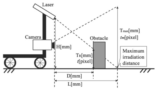
Figure 1.
Obstacle height measurement method using a monocular camera and line laser (measurement algorithm).
The system estimates depth by computing the displacement of the laser line relative to a known reference, based on the geometric relationship between the camera and the laser emitter. However, this approach faces limitations in complex environments such as stairs or uneven terrain. It lacks the capability to capture precise 3D spatial information necessary for real-time path planning. Specifically, it cannot accurately identify critical environmental features such as obstacle geometry, type, depth, or the structural configuration of staircases. Consequently, its applicability in dynamic and unstructured environments is constrained, limiting its potential use in fully autonomous navigation systems.
In this study, we propose an autonomous self-controlled mobility system that integrates 3D spatial recognition using a monocular camera and a laser, enabling obstacle recognition and shape measurement via convolutional neural networks (CNNs), as well as stair structure recognition. CNNs are a type of deep learning model widely employed for image recognition, object detection, and feature extraction tasks. The primary features of the proposed system are (1) multi-environment adaptive 3D analysis, which cannot be achieved using a monocular camera alone; (2) accurate obstacle detection even under low-light conditions; and (3) lower cost compared to other sensors used in fully autonomous robotic systems. Specifically, the algorithm employs CNNs to segment obstacle regions from the monocular camera feed. Within these segmented regions, the system detects laser stripes by analyzing the intensity and geometric features of characteristic pixels. Using the laser’s projected position and the camera’s intrinsic parameters, the system computes not only the height and distance of obstacles but also their depth. Furthermore, the system can identify stair-like structures by estimating parameters such as riser height, tread depth, and the number of steps. Consequently, the proposed algorithm enables real-time 3D perception of the surrounding environment, supporting autonomous navigation of the electric wheelchair in complex and unstructured spaces.
This paper presents two main contributions: (1) a three-dimensional obstacle detection method using CNN, and (2) a stair structure recognition algorithm capable of estimating step height, depth, and number of steps. After introducing these proposed techniques, we describe the evaluation methodology used to verify their effectiveness. We then explain the experimental setup and procedures, present the results, and conclude with a discussion and future work.
The paper is organized in the following order: Introduction, Proposed Method, Validation of Effectiveness, Experimental Setup, Experimental Results, and Conclusion. The experiments were conducted in two stages: first, a preliminary validation using a small-scale autonomous mobile robot, followed by a demonstration experiment using a fully autonomous electric wheelchair under real-world environmental conditions.
2. Materials and Methods
This study proposes a self-controlled autonomous mobility system integrating 3D spatial recognition using a monocular camera and laser, CNN-based obstacle recognition and shape measurement, and stair structure recognition technology. The proposed method integrates a monocular camera and laser with YOLO and CNN to identify obstacle regions, binarize only the target area, and extract feature points for efficient and accurate 3D distance measurement and recognition of obstacles and stair structures. YOLO stands for “You Only Look Once,” which is a real-time object detection algorithm. It is widely used in computer vision for detecting and classifying objects quickly and accurately. By filtering out irrelevant information, the CNN suppresses noise and enables stable detection in dynamic and complex environments. Compared to LiDAR and millimeter-wave radar, the proposed method is more cost-effective while maintaining high measurement performance under low-light conditions—one of the key advantages of the system.
As shown in Figure 2, this study introduces a novel autonomous mobility system by integrating 3D measurement-based obstacle detection and stair structure recognition into a fully automated electric wheelchair capable of stair traversal. By integrating monocular visual sensing with laser-based spatial recognition, the system achieves robust environmental perception regardless of illumination and enhances mobility within complex three-dimensional environments. The proposed approach addresses a significant limitation of conventional mobility aids and contributes a foundational technology toward expanding the daily living range of elderly and physically impaired individuals, thereby advancing the realization of a truly barrier-free society.
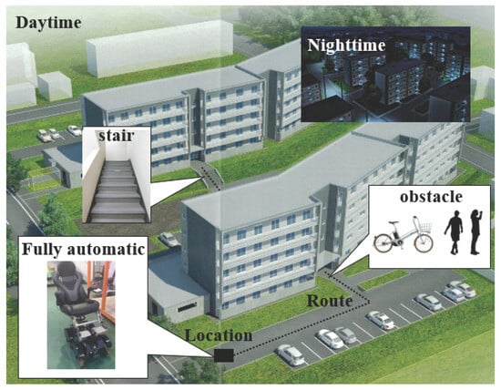
Figure 2.
Ideal detection targets for self-regulating autonomous moving mechanisms.
2.1. Obstacle Recognition and Shape Measurement Using CNN
To achieve 3D spatial recognition using a monocular camera and laser, feature points are detected from the characteristics of the laser visible in the camera image. By incorporating a CNN, object detection can be performed, and laser feature points can be extracted with high accuracy. The CNN offers low computational cost in real-time detection while maintaining high accuracy in obstacle recognition and 3D distance measurement. Its ability to efficiently capture complex patterns, such as stair structures, ensures stable performance in dynamic environments, making it ideal for this system.
Figure 3 illustrates the image analysis process up to the point at which the laser is detected. First, the input square image is divided into smaller S × S grid cells. Each grid cell is assigned a number of bounding boxes, each of which is comprised of five parameters: the x and y coordinates of the center; the width and height of the box; and the confidence score. For instance, if three bounding boxes are assigned to one grid cell, the five parameters are used to determine whether each box corresponds to a background or an object, and the class to which each grid cell belongs is determined. Increasing the number of classes allows for the detection of more types of obstacles. In this way, approximately 100 classes are defined. The probability of each class for each grid cell is calculated, and the class with the highest probability is output. A class decision is made for each grid cell, and the object’s range is determined by color-coding. The definition of approximately 100 classes is not intended to represent 100 distinct obstacle types, but rather to enhance the granularity of detection by accounting for variations in reflection, size, and shape. This approach improves the robustness of obstacle recognition in diverse environments while maintaining a balance between detection accuracy and computational efficiency.
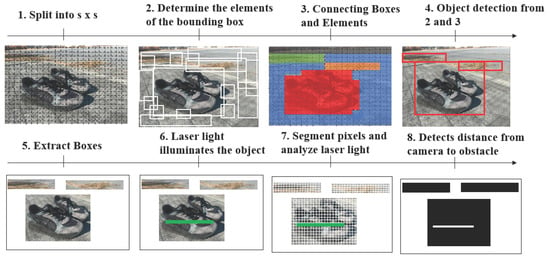
Figure 3.
Flow of object detection and laser feature inspection using a CNN.
To select the most appropriate class from multiple bounding boxes, non-maximum suppression is performed. This involves selecting the bounding box with the highest confidence for each class and removing overlapping boxes (based on the Intersection over Union [IoU]) if they overlap above a certain threshold. The detected objects are then extracted, and the object illuminated by the laser is automatically selected. To precisely detect the pixel coordinates of the laser light, pixel segmentation is performed within the detected object. Finally, by converting the most laser-adjacent HSV hue to white color information and all other colors to black, it becomes possible to detect the object type and the laser light on the object with high precision. HSV means Hue, Saturation, and Value, which is a color model used to represent and process colors in image analysis. Figure 4 shows a simplified flow of CNN for object recognition and laser detection when an image is input. To detect an object such as a shoe, the laser light on the shoe is detected by convolutional layers that extract local features, such as edges and color changes. A pooling layer is added to provide translation invariance so that extracted features are not affected by movement. Based on the extracted features, the fully connected layers perform final classification and prediction to detect the object. Finally, an image containing the laser light in the detected objects is selected.
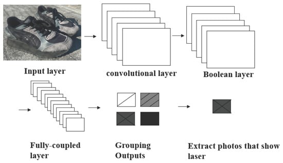
Figure 4.
Process of extracting the pixels where the laser light appears in the input image.
The CNN in this study uses a composite loss function to optimize object detection. This loss function consists of three components: coordinate loss , confidence loss , and class loss . Each component is calculated using mean squared error, and the final loss L is expressed as
First, the coordinate loss is defined as
Here, (, ) are the predicted center coordinates of the bounding box, (, ) are its width and height, , , , are the corresponding ground truth values, S × S denotes the grid size, B is the number of bounding boxes per grid cell, is an indicator function that is 1 if object j is present in cell i, and is a hyperparameter controlling the coordinate loss weight.
The indicator is a binary variable used in the CNN loss function. It takes a value of 1 if object j is present in grid cell i, and 0 otherwise. This mechanism ensures that the coordinate loss and the confidence loss are computed only for cells containing objects. In other words, the network ignores empty cells () during loss computation, preventing the loss function from being influenced by regions without objects. This selective computation is essential, as it allows the CNN to focus on accurately predicting the positions, dimensions, and confidence scores of objects while avoiding penalties from empty areas.
Next, the confidence loss is given by
where is the predicted confidence score for grid cell i, and is the corresponding ground truth confidence. The indicator equals 1 if no object is present in grid cell i, and 0 otherwise. The hyperparameter weights the contribution of these empty cells to the confidence loss, ensuring that the network is penalized when it predicts high confidence in cells without objects. By explicitly including this term, the loss function accounts for both object and non-object regions, which is critical for stable training and improving overall detection accuracy.
The class loss is defined as
where is the predicted probability for class c in grid cell i, and is the ground truth probability. By minimizing this loss function, the CNN detects object areas illuminated by the laser, extracts the corresponding image regions, and converts this data into distance information using triangulation-based post-processing.
In this study, the ground truth is defined using manually annotated laser reflection points in the camera images. For instance, when the laser spot appears on the tip of a shoe at pixel coordinates (120, 80) with a bounding box of 30 pixels in width and 20 pixels in height, these parameters are adopted as the ground truth position and size. The ground-truth confidence value is assigned as one for the grid cell containing the shoe and zero for all other cells. Similarly, ground-truth class probabilities are represented as one-hot vectors; that is, if the detected object corresponds to the “shoe” class, the probability for “shoe” is set to one, and all other class probabilities are set to zero. This annotation approach enables the CNN to accurately learn the position, size, and class of laser-illuminated objects within the images.
Figure 5 presents a model for detecting the height and depth of an object based on the feature points of a laser beam projected onto the camera image. Let us assume that the maximum distance of the laser beam is x. In this model, and represent the distances from the camera to the tip and back of the shoe, respectively, while and represent the distances from the camera to the tip and back of the block. The corresponding heights of the shoe and the block are and . The distance to the object, as well as its height and depth, can be calculated from the camera image by first determining the heights in the image plane using the number of pixels corresponding to the feature points. Specifically, let H be the height of the laser beam, the number of pixels in the camera image corresponding to the maximum exposure distance x, and the actual distance in the camera image corresponding to this maximum distance. The pixel counts at the tip and back of the shoe are denoted as and , respectively, while the pixel counts at the tip and back of the block are and . The heights in the image plane () are first computed using Equation (7), and then the actual distances from the camera to the feature points () are obtained using Equation (7). In this way, the model translates the 2D pixel measurements of the laser projection into 3D physical distances and heights of the object.
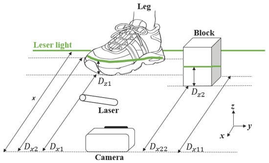
Figure 5.
Distance, height, and depth detection for the target object.
To detect the depth information of obstacles, the distance from the camera to the nearest and farthest parts of the obstacle is individually calculated based on the laser-detected feature points, and the depth is obtained by subtracting the nearest distance from the farthest one. This differential method, as shown in Equations (8) and (9), allows precise estimation without requiring full 3D reconstruction. In the context of this study, denotes the distance to the shoe, while indicates the distance to the block.
2.2. Stair Structure Recognition Technique
This paper proposes a method for detecting the number, height, and depth of stairs using a monocular camera and laser. When an autonomous robot ascends or descends stairs, varying step heights and depths prevent the use of a single motion pattern for all steps. In low-light environments, such as nighttime, detecting the height and depth of stairs using only the monocular camera is particularly challenging. However, when a laser is used, the height and depth of stairs can be detected accurately even in the dark. While the depth of the stairs does not appear in the monocular camera’s image, the laser allows the detection of information outside the visible range of the camera.
This method allows for real-time detection of the height and depth of all steps visible in the camera image. Since the method uses both the monocular camera and the laser, it can detect the number, height, and depth of steps even in low-light conditions. Figure 6 contains a model diagram of the stair structure recognition technique using the monocular camera and laser. Specifically, the actual height of each step , , , and , and depth of each step , , , and can be detected. This is accomplished by adjusting the laser’s emission angle towards the stairs in front of the camera.
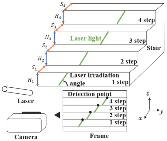
Figure 6.
Feature point detection on stairs using diagonally emitted laser.
Figure 7 shows a binarized image. By angling the laser, light is emitted at each step of the stairs. Although the depth of the stairs is not visible in the image, distance calculations based on the laser feature points allow determination of the straight-line distance from the camera, thereby enabling accurate detection of each step’s depth. By adjusting the laser’s emission pattern, the light is grouped for each step. For example, the laser light emitted onto the first step is Group 1, the second step Group 2, and so on. By detecting the pixel coordinates of the topmost part of the detected group, the height and depth of each step can be determined. The number of groups corresponds to the number of steps. The variable n denotes the index number assigned to each laser beam detected on the stairs within the camera image. Specifically, because the laser is projected diagonally onto the front-facing stairs, the beams are grouped according to individual stair steps. For each group, the pixel coordinate of the uppermost laser point is extracted, and the total number of these detected points is defined as n. Figure 8 presents a side view of Figure 6. Let the height from the ground to the first step be , and that from the ground to the second step be . The height of each step can be calculated as shown in the following equations. This calculation model allows for the detection of the height and depth of all steps visible in the camera image.
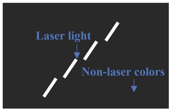
Figure 7.
Binarized image of stair structure recognition.
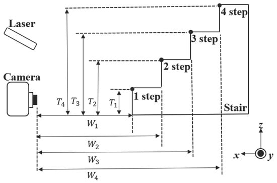
Figure 8.
Detectable stair parameters.
Figure 8 presents a side view of the experimental setup, illustrating the parameters used for detecting the depth of the stairs. Furthermore, the depth of each step can be calculated using Equation (15). The distance from the camera to the first step, the distance to the second step, and the distance to the n-th step can be determined using trigonometry by calculating the height of the stairs, as shown in Equations (13) and (14). It should be noted that W represents the distance from the camera to the stairs, and not the depth of the stairs.
Using Equations (13) and (14), the depth of each step can be calculated as shown in Equation (15). Since W represents the distance from the camera to each step, subtracting the W of the lower step from that of the step immediately above it allows the detection of the depth of the upper step. By repeating this process for all steps, an algorithm is formed that can calculate the depth of all steps.
3. Efficacy of Method
To verify the effectiveness of the self-controlled autonomous movement mechanism integrated with 3D spatial recognition using a monocular camera and laser, obstacle recognition and shape measurement with CNN, and stair structure recognition technology, a path-planning method was combined. Principle analysis and algorithm construction were performed using a small autonomous movement platform, and feasibility was determined by applying it to a fully omnidirectional self-controlled autonomous electric wheelchair. Figure 9 shows the small autonomous movement platform. By combining the main board with an Arduino UNO and controlling four motors, two front and two rear Mecanum wheels were operated. The use of Mecanum wheels enabled omnidirectional movement—including forward, backward, lateral, diagonal, and rotational motions—allowing the robot to accurately avoid complex obstacles [25,26]. Table 1 presents the specifications of the small omnidirectional robot used in this study, which is equipped with Mecanum wheels and capable of moving in any direction.
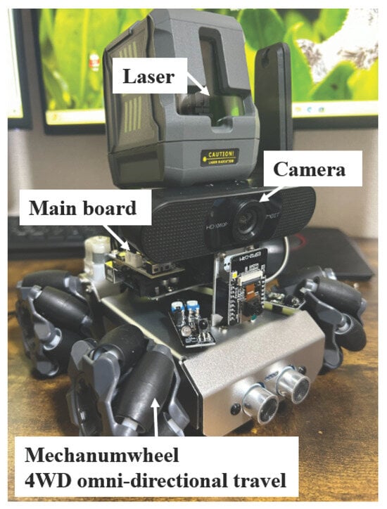
Figure 9.
The small autonomous movement mechanism.

Table 1.
Specifications of the small omnidirectional robot.
A platform was constructed in the small autonomous movement platform with the A-star path planning method that integrated 3D spatial recognition, obstacle recognition, and measurement using a monocular camera and laser, along with stair structure recognition via CNN. Autonomous robots can be categorized as autonomous robots, exploration robots, SLAM-based robots, and reactive robots, each with distinct operational characteristics. SLAM (Simultaneous Localization and Mapping) is a method that allows a robot or autonomous system to build a map of an unknown environment while simultaneously estimating its own position. For this study, we used a navigation robot with a predefined destination [27,28,29,30,31,32,33,34,35].
To verify the effectiveness of the proposed method integrating 3D spatial recognition with monocular cameras and lasers, object recognition and shape measurement with CNN, and stair structure recognition techniques, we incorporated a path-planning method. Figure 10 shows the algorithm flow of the proposed method, and Figure 11 illustrates the path planning of the small autonomous movement mechanism with integrated object and stair detection.
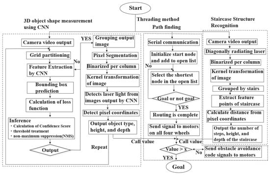
Figure 10.
Parallel processing of three algorithms: obstacle recognition and shape measurement using monocular camera and laser with CNN; omnidirectional self-controlled autonomous movement with A-star path planning; and stair structure recognition using monocular camera and laser.
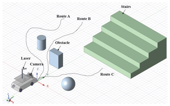
Figure 11.
Path planning of the small autonomous moving mechanism with integrated obstacle and stair detection.
As shown in Figure 10, the proposed method implements three algorithms simultaneously in parallel on a single platform: (1) obstacle recognition and shape measurement using a monocular camera and laser with CNN; (2) A-star path planning; and (3) stair structure recognition with monocular cameras and lasers, enabling real-time processing. For (1), the camera is activated, and the input image is resized to a fixed size suitable for the model. The input image is then divided into an S × S grid, with each grid cell responsible for a specific region within the image. CNN is used to extract image features, and by using Darknet-53 (Darknet-53 is a 53-layer convolutional neural network used as the backbone of YOLOv3 (original version), providing a good balance between accuracy and speed, making it effective for real-time object detection), a high-precision and fast network can be realized. Each grid cell predicts information such as the center coordinates, width, height, confidence score, class probability distribution, and output tensor shape of bounding boxes. During the learning process, the coordinate loss, confidence loss, and class loss are computed to minimize the loss function. Subsequently, inference processes such as confidence score calculation, threshold processing, and non-maximum suppression (NMS) are performed. The final bounding boxes and class labels are output, and the images are grouped. After grouping, pixel segmentation and binarization processing are applied. Kernel transformation is applied repeatedly for image dilation and compression, reducing noise from non-laser regions. Only the portions where laser light is present in the grouped images are extracted. Finally, by outputting the pixel coordinates in the frame and substituting them into the distance calculation formula of the proposed method, the type, depth, height, and distance to the obstacle can be detected simultaneously in real time.
For stair structure recognition using monocular cameras and lasers (3), the camera captures an image, and the laser is emitted at an oblique angle. Pixel segmentation and binarization using kernel transformation are applied. Laser light is segmented into groups corresponding to each stair step, and the pixel coordinates of these groups within the frame are detected. As shown in Figure 8, the highest point of each step is extracted as a feature point. This allows the height and depth of the stairs to be detected simultaneously. Finally, by substituting the results into the distance calculation formula of the proposed method, the number of steps and the height and depth of each step can be detected in real time.
In omnidirectional self-controlled autonomous movement with A-star path planning (2), the values obtained from obstacle recognition and shape measurement using monocular cameras and lasers, as well as stair structure recognition, are continuously retrieved and processed. Once the path generation is complete, control signals are sent to the four motors. If the retrieved values indicate an obstacle or stair, an avoidance code is created, and the robot navigates to the destination. For example, if the distance to an obstacle or stair is 50 mm and the depth is 10 mm, the robot stops, generates an avoidance code, and sends control signals to proceed safely. By performing the three processes simultaneously in parallel, an omnidirectional self-controlled autonomous movement mechanism is realized. As shown in Figure 11, multiple path patterns exist for the small autonomous movement mechanism based on the timing and location of obstacles or stairs. The program selects the shortest path to the destination, ensuring arrival in minimal time.
Figure 12 and Figure 13 illustrate the feasibility of the omnidirectional self-controlled autonomous electric wheelchair and its organizational diagram, respectively. The components shown in Figure 13 are listed in Table 2. To achieve omnidirectional movement and stair climbing, three mecanum wheels were mounted on the drive shaft of each motor. Thus, the electric wheelchair is equipped with a total of 12 wheels, driven by four motors. To maintain horizontal alignment of the chair with the ground during stair climbing, four additional motors are installed in the chair. Figure 14 illustrates the control system and signal pathways to the motors, as well as the relationship between the camera and remote controller. The system was constructed similarly to the small autonomous movement mechanism shown in Figure 9.
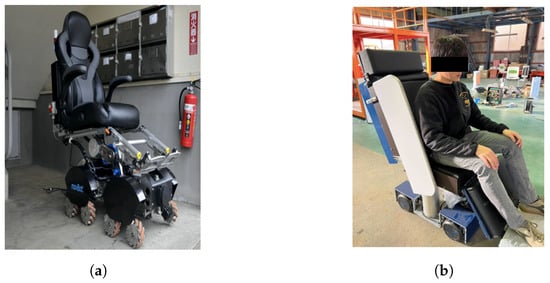
Figure 12.
Omnidirectional autonomous electric wheelchair. (a) Fully autonomous electric wheelchair; (b) state of boarding.
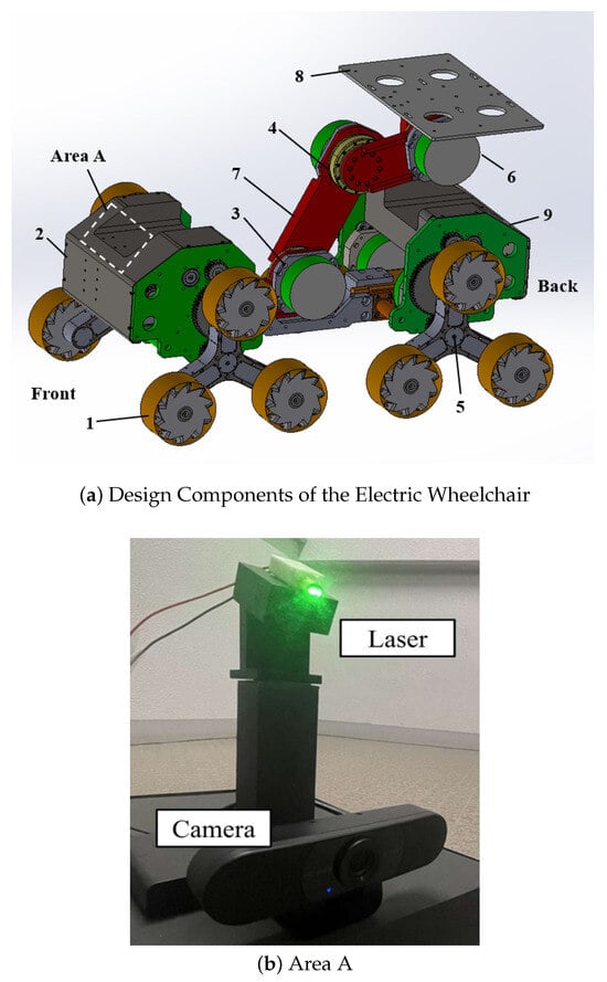
Figure 13.
Electric wheelchair with omnidirectional mobility.

Table 2.
Main components of the omnidirectional electric wheelchair.
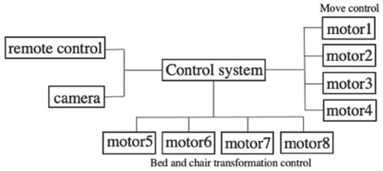
Figure 14.
Simplified control diagram of the omnidirectional self-controlled autonomous electric wheelchair.
The motion model of a mecanum-wheeled mobile robot plays a crucial role in achieving omnidirectional movement and efficient path planning, particularly in environments that require obstacle avoidance. Mecanum wheels enable the robot to move in any direction without changing its orientation by appropriately adjusting the rotational speed of each wheel. To mathematically describe this motion, it is necessary to establish the relationship between the robot’s translational and rotational velocities and the angular velocities of its individual wheels. Let r denote the radius of each wheel, while L and R represent the distances from the robot’s center to the wheels in the longitudinal (forward/backward) and lateral (left/right) directions, respectively. The robot’s translational velocities in its local coordinate frame are denoted as (forward) and (lateral), and represents the angular velocity around the vertical axis. The heading direction of the robot in the global coordinate frame is denoted by , which is used to transform local velocities into the global frame for accurate navigation. Based on these definitions, the inverse kinematics of the mecanum drive can be expressed by the following motion model (Equation (16)), which computes the angular velocities , , , and of the four wheels.
In the A-star algorithm, if the evaluation value of node n is , the real cost from the start node to node n is , and the estimated cost from node n to the goal node is . The path that minimizes the evaluation function can be expressed as
where Equation (17) presents the evaluation function used to compute the cost of a given node.
The cost function , considering the mecanum wheel, can be expressed as follows:
where k is the number of movement steps up to the current point, and are the positions of the robot at step i, is the robot’s orientation at step i, and is the weight of rotation cost. Equation (18) describes the real cost calculation based on the number of movement steps and the robot’s orientation at each step.
Furthermore, the heuristic function based on the Euclidean distance is reformulated, as shown in Equation (19), to estimate the cost from the current node to the goal. In this equation, represents the heuristic cost for node n, (, ) denotes the coordinates of the goal position, and (, ) represents the current coordinates of node n. This function calculates the straight-line (Euclidean) distance between the current node and the goal, providing an admissible and consistent heuristic for A* path planning in a 2D space.
Finally, a state transition model is constructed based on the motion behavior of the mecanum-wheeled robot. The future position and orientation of the robot, denoted as , , and , are predicted from the current state variables , , and , along with the control inputs , , and , which represent the translational velocities in the robot’s local forward/backward and lateral directions, and the angular velocity around the vertical axis, respectively. The time increment is represented by . This model incorporates the robot’s orientation when transforming local velocities into global coordinates, ensuring accurate position tracking during omnidirectional motion enabled by the mecanum wheels. The state update equations are given in Equation (20) as follows:
Based on the measured distances to obstacles, as well as their height, depth, and the distance to the stairs, the mecanum-wheeled robot generates an avoidance command. The system then re-evaluates the A* pathfinding algorithm to update the optimal route and subsequently transmits the corresponding control signals to navigate toward the target destination.
4. Experimental Environment
To verify the effectiveness of the proposed method, we conducted experiments using a small-scale autonomous mobile robot integrated with a path planning algorithm. These experiments evaluated the capability of real-time obstacle shape measurement and stair structure recognition. Furthermore, in consideration of practical feasibility, the proposed method and path planning were implemented in a fully autonomous electric wheelchair capable of stair navigation. Accordingly, the validation of the proposed method consists of two stages, presented in the following sections. Although previous studies have proposed distance measurement methods using a monocular camera and laser, they typically report a maximum error of 2.35 cm [36]. However, such methods are not capable of real-time processing and only measure the distance to obstacles without performing three-dimensional shape reconstruction or stair structure recognition. In contrast, the proposed method enables both real-time processing and 3D spatial measurement, including the recognition of stair geometry. Thus, while the previously reported accuracy serves as a reference, the proposed method provides a more comprehensive and practical solution for autonomous navigation in complex environments.
The scalability from a small-scale prototype to a full-size electric wheelchair is theoretically robust. Specifically, the algorithms for obstacle detection, shape reconstruction, and stair recognition rely solely on image and depth information, which are independent of the physical size of the platform. The computational complexity and processing time are determined by the resolution of the sensing devices and the efficiency of the implemented algorithms, rather than by the scale of the robot itself. Therefore, whether applied to a small mobile robot or a full-size electric wheelchair, the perception and decision-making framework operates under the same computational constraints and produces consistent results. In addition, the transition from prototype to wheelchair was facilitated by adjusting only the actuation parameters, such as wheel diameter and motor torque, while leaving the sensing, recognition, and planning modules unchanged. This demonstrates that the proposed method maintains its effectiveness across different physical scales, thereby substantiating the robustness of the transition from a small-scale prototype to a fully functional autonomous wheelchair.
As a supplementary experiment, we evaluated the response time from distance measurement to motor control signal transmission. The response time of the small-scale mobile robot was 45 ms, whereas that of the full-size autonomous wheelchair was 60 ms. This slight difference is negligible for overall system performance and does not affect the practical feasibility of the proposed method. Various approaches can further reduce the response time, including optimizing image processing, implementing parallel computation on GPUs, or refining control signal transmission. These options demonstrate that the system’s responsiveness can be improved without altering the fundamental scalability of the proposed framework.
4.1. Experimental Setup of the Small Autonomous Mobile Mechanism
To verify the proposed method, principal analysis and algorithm development were conducted on a small autonomous mobile mechanism, and feasibility was assessed using an omnidirectional self-controlled autonomous electric wheelchair. As shown in Figure 15, the experiment with the small autonomous mobile mechanism was conducted indoors, while that with the omnidirectional self-controlled autonomous electric wheelchair was conducted outdoors (Figure 16). The white dashed lines indicate the trajectory of the robot as it performs pathfinding, detects suddenly appearing obstacles, generates avoidance paths, and moves towards the destination. In both experiments, real-time object detection, distance calculation, and stair detection were performed, and synchronization was maintained between the robot and the system built with the proposed method.
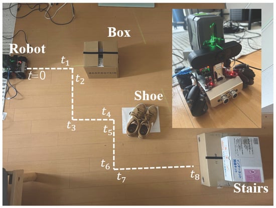
Figure 15.
Environment for the small autonomous mobile mechanism experiment (indoors).
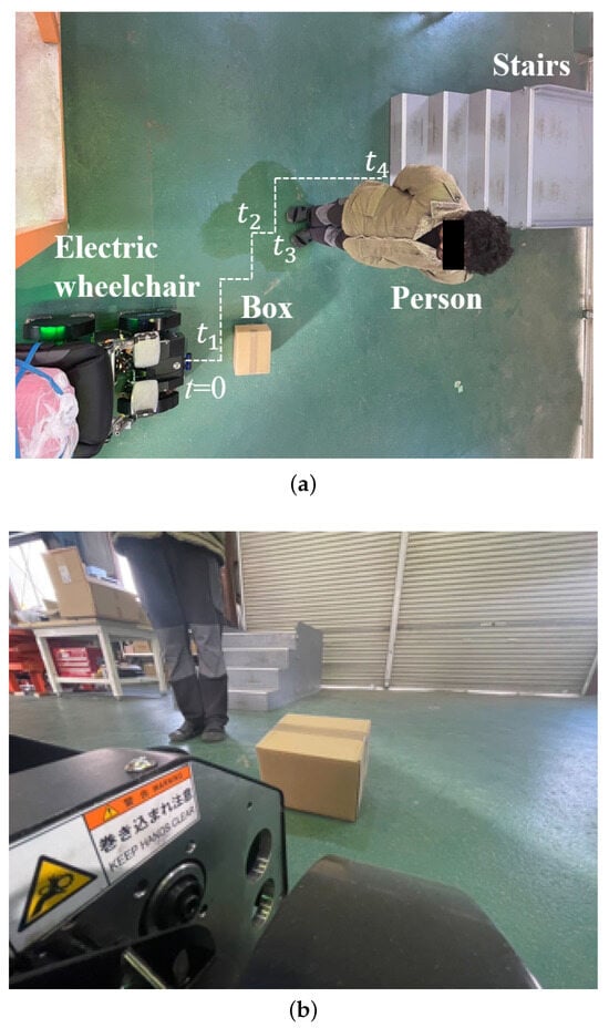
Figure 16.
Environment for the omnidirectional self-controlled autonomous electric wheelchair experiment (outdoors). (a) Experimental environment viewed from above; (b) image captured from the perspective of the electric wheelchair.
New signals were continuously sent to the robot, and temporal points (n = 1, 2, 3, …) were set at moments where behavioral changes were expected, as shown in the figures. By setting these temporal points, it was possible to clarify the behavior of the motor controls driving the wheels of the robot at each moment in time. In both experiments, the robot stopped and generated an avoidance path when the distance to an obstacle was 360 mm or less; otherwise, it generated the shortest path to the destination and sent control signals to the motors.
4.2. Experimental Setup of the Omnidirectional Self-Controlled Autonomous Electric Wheelchair
In the small autonomous mobile mechanism experiment, we verified that the proposed method was robust to environmental illumination by conducting experiments under two conditions: bright and dark. Additionally, obstacles in the form of rectangular boxes, shoes simulating human feet, and simple models simulating stairs were set up. Since the small autonomous mobile mechanism with integrated pathfinding can navigate to the destination regardless of obstacle positions, the obstacles were placed arbitrarily. In the experiment with the omnidirectional self-controlled autonomous electric wheelchair, for practical reasons, obstacles included humans, cardboard, and real stairs. In the small autonomous mobile mechanism, stair structure recognition was performed, and the robot stopped at a specific distance from the stairs. In the case of the omnidirectional self-controlled autonomous electric wheelchair, stair structure recognition was performed, and the wheelchair executed the sequence to climb the stairs when it was a specific distance from them.
The omnidirectional self-controlled autonomous electric wheelchair stops for dynamic obstacles, such as humans, bicycles, and automobiles, and resumes motion once they are no longer detected by the camera. For static obstacles, it generates and executes an avoidance path closer to the destination. Furthermore, since the proposed method can identify the type of obstacle, the system can predict whether the obstacle is static or dynamic in advance. Because the depth of obstacles can be detected, control signals can be sent with flexible adjustments to the motor’s operation time in the avoidance code. Additionally, because the height and depth of all stairs can be detected with high precision, control signals to the motors for each step can be flexibly adjusted.
For safety considerations, all field trials, including outdoor experiments, were conducted on private premises with access restricted to authorized personnel only. Obstacles and experimental setups were carefully arranged to minimize the risk of accidental collisions, and all equipment was thoroughly inspected prior to each trial. The robots were operated at controlled speeds, and emergency stop functions were activated to allow immediate termination of motion when required. These safety measures ensured the protection of participants, equipment, and the surrounding environment throughout the experiments.
5. Results
5.1. Experimental Results of the Small Autonomous Mobile Mechanism
Figure 17 presents the results of the mecanum wheels’ behavior implemented in the small autonomous mobile mechanism using the proposed method, Figure 18 presents the corresponding camera and binarized images at the specific points illustrated in Figure 15. Figure 19 displays camera images of the types of obstacles detected using CNN, while Figure 20 shows the camera images with detected stair parameters, including the number of steps, depth, and height. These experiments play an essential role in validating the performance of the proposed method, as the robot’s behavior at each time interval is documented along with the timeline.
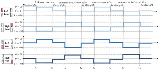
Figure 17.
Results of the mecanum wheels’ behavior in the small autonomous mobile mechanism implementing the proposed method.
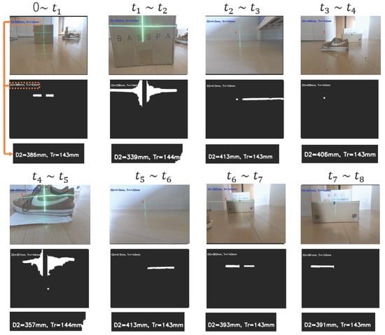
Figure 18.
Camera images and binary images at the points shown in Figure 15.
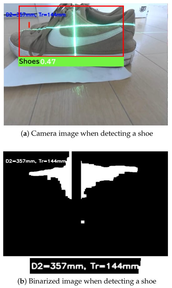
Figure 19.
Camera images detecting types of obstacles.
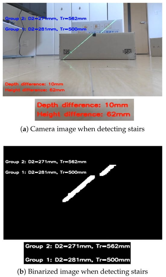
Figure 20.
Camera images for stair structure recognition.
In Figure 17, the horizontal axis represents the elapsed time of the experiment, and the vertical axis shows the wheel rotation angles. For example, when all four wheels are set to 0 degrees, the robot moves straight ahead. When the rotation angles of all wheels are set to 90 degrees, the robot moves directly to the right. Conversely, when the left wheel is set to 90 degrees and the right wheel to -90 degrees, the robot rotates in place to the right. Adjusting the rotation angles of the wheels enables movement of the robot in the desired direction. This control scheme leverages the advantages of the mecanum wheels, enabling omnidirectional movement and allowing the robot to freely navigate in various directions. The control signals are transmitted to the robot through the Arduino IDE platform, enabling real-time control.
As mentioned, the time shown on the horizontal axis corresponds to specific time points indicated in Figure 15, where the robot’s behavior during each stage of the experiment is recorded in detail. Based on Figure 17, during the time intervals 0 to , to , to , and to , there are no obstacles or stairs in the robot’s forward direction. All wheels are set to 0 degrees during these periods, and the robot moves straight ahead, confirming that it performs as intended. In contrast, during the time intervals to , and to , obstacles are detected in the robot’s forward direction, and it performs evasive maneuvers, adjusting its movement by rotating and generating an avoidance path. These results indicate that the proposed method effectively enables dynamic obstacle avoidance based on real-time detection. However, during to , the robot performs only lateral parallel movement, with no obstacle detection occurring. This behavior is governed by control signals from the path planning algorithm and is unrelated to obstacle detection. Finally, the robot moves straight ahead for several seconds after and then stops, indicating the successful detection of stairs.
Figure 18 shows the results of real-time obstacle detection using CNN. The system accurately detected various parameters of obstacles, including the type, shape, distance, height, depth, and number of steps. Notably, in the binarized images, vertical lines from the laser were disregarded, and appropriate masking was applied. Therefore, all the results are derived from real-time processing. The binarization processing accurately extracted the laser light reflected off the obstacles, enabling precise output based on the detected numerical data from the camera images. When the distance from the robot to the obstacle exceeded 360 mm, it followed the path planning algorithm; when the distance was 360 mm or less, it stopped and executed avoidance behavior, demonstrating the effectiveness of the proposed method in executing avoidance behavior based on real-time distance measurements. The maximum error between the actual distance and the distance measured using the proposed method was 0.8 cm. In comparison, the maximum error in previous studies was 2.35 cm, confirming that the proposed method is 1.55 cm more accurate. The maximum error of 0.8 cm corresponds to the average of three experimental runs. The standard deviation of the error across these runs was approximately 0.12 cm, indicating that the proposed method provides consistent and reliable distance measurements in repeated trials. The height of the obstacle is an important parameter for detecting the distance , which is essential for precise distance measurement. Figure 19 shows the successful implementation of object detection using the CNN and laser. Ultimately, based on the class extracted from the bounding box, the obstacle was identified as a shoe. The precise binarization of the laser-illuminated area allows for accurate detection of the obstacle’s position, and especially in outdoor environments, the high probability of detecting the position of shoes when detecting humans further confirms the high feasibility of the proposed method.
Figure 20 illustrates the detection of stair parameters, including the number of steps, as well as their depth and height. As shown, the system detected two steps with a measured depth of 10 mm and a height of 62 mm. In comparison, the actual depth and height of the steps were 12 mm and 60 mm, respectively, indicating a discrepancy of 2 mm in both dimensions. Nevertheless, the number of steps was detected with high accuracy. In the binarized images, the diagonal emission of the laser beam caused interruptions at the stair edges, which enabled the grouping of white linear segments. Using this grouping approach, the number of detected lines increased or decreased according to the actual number of steps. Finally, by extracting laser feature points from the binarized images, the robot was able to perform 3D spatial analysis of its surroundings while navigating, avoiding obstacles, and recognizing stairs.
Figure 21 shows the results of detecting complex-shaped obstacles using the proposed method. Specifically, U-shaped and T-shaped obstacles were employed. As shown in the figure, the proposed method accurately extracts laser light reflected from the obstacles. Distance measurements were performed three times, resulting in an average error of 0.42 cm. Furthermore, Figure 22 presents the results of detecting dynamic obstacles using the proposed method. A two-wheeled small mobile robot was used as the dynamic obstacle. The robot was driven by a stepping motor switched on and off to move at a constant speed. The figure demonstrates that the laser light reflected from the dynamic obstacle can be extracted in real time with high accuracy. The robot was moved laterally while keeping its distance from the camera constant. Distance measurements were conducted three times, resulting in an average measurement error of 0.11 cm. This small error is attributed to the constant distance maintained during the experiment. Currently, the IBA and IFGM algorithms have been shown in simulations to achieve high-performance navigation for U- and H-shaped obstacle avoidance in a safe and autonomous manner. By combining the sensors used in the proposed method, it is expected that high-precision obstacle avoidance can also be realized experimentally [37].
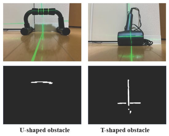
Figure 21.
Detection of U- and T-shaped obstacles.
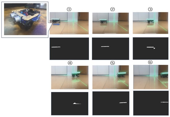
Figure 22.
Detection of dynamic obstacles using a two-wheeled small robot (Items ➀ to ➅ show the camera images and binarized images captured every second as the small robot moves. Therefore, ➀ corresponds to 1 second, and ➅ corresponds to 6 s).
To quantitatively evaluate the performance of the proposed method, key metrics including accuracy, reliability, and processing speed were measured during the experiments. Table 3 summarizes the results. The maximum distance measurement error for static obstacles was 0.8 cm, with a standard deviation of 0.12 cm over three repeated trials. For complex-shaped obstacles (U- and T-shaped), the average measurement error was 0.42 cm. For dynamic obstacles, the average measurement error was 0.11 cm when the relative distance was maintained constant. For obstacle type identification using CNN, the accuracy of 88% was calculated based on 50 test cases, including static objects (boxes, shoes, stair models) and dynamic objects (moving small robots), resulting in an accuracy of 88%. The average processing time per frame for real-time obstacle detection, stair recognition, and distance calculation was approximately 45 ms, confirming that the system operates in real time. These results demonstrate that the proposed method is highly accurate, reliable, and suitable for practical autonomous navigation in complex environments.

Table 3.
Performance metrics of the proposed method.
In recent years, LiDAR systems used for automotive applications, such as inter-vehicle distance measurement, have achieved a measurement accuracy of approximately 2 cm [38]. In comparison, the proposed method demonstrates more than twice the measurement accuracy for obstacle detection. Moreover, the method offers additional advantages, including independence from the reflectivity of obstacles and cost-effectiveness.
5.2. Experimental Results of the Omnidirectional Self-Controlled Autonomous Electric Wheelchair
The behavior of the omnidirectional self-controlled autonomous electric wheelchair implementing the proposed method is shown in Figure 23, using camera and binarized images captured at specific points from Figure 16. The stair ascent and descent observed after stair detection is presented in Figure 24. In Figure 23, between 0 and , the electric wheelchair approaches an obstacle. Upon detecting the distance to the obstacle below the predetermined threshold at , it automatically stops. At , it approaches a human. At , when the distance to the human reaches a predefined value, it stops again. Finally, the wheelchair recognizes the structure of the stairs, confirming its ability to appropriately ascend and descend them. When the distance from the wheelchair to an obstacle becomes less than 360 mm, it automatically halts, and control signals are transmitted to the motors to execute an avoidance maneuver. If no obstacles are within 360 mm, control signals are sent based on the pathfinding algorithm, allowing continuous movement. The laser light is accurately extracted at all measurement points, and the system can distinguish between different types of obstacles, such as boxes and humans. Additionally, precise distance measurements from the wheelchair to objects are obtained from the binarized images, confirming that the wheelchair can successfully avoid obstacles while moving.
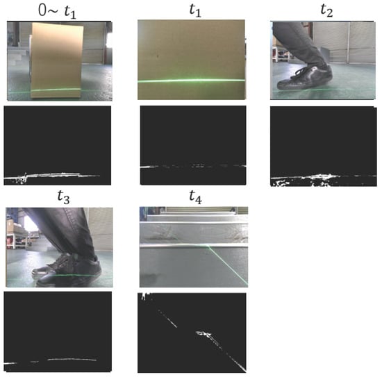
Figure 23.
Camera and binarized images at the points indicated in Figure 16.
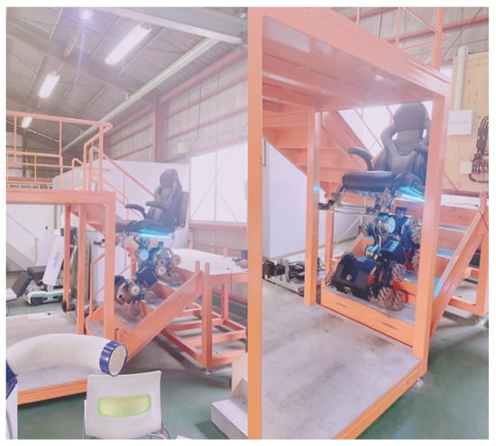
Figure 24.
Stair climbing behavior of the omnidirectional self-controlled autonomous electric wheelchair.
For stair detection, the laser light used to measure the height and distance of obstacles is emitted from the highest and leftmost pixel coordinates in the camera frame, preventing interference from ground reflections. This enables more accurate recognition of object structures. The proposed method uses green laser light, and tests on a green surface verified that even when the laser and ground were the same color, the laser was accurately extracted in binarized images. This confirms the robustness of the method across various environmental conditions. Figure 25 demonstrates the recognition of stair height and depth, confirming that the electric wheelchair can successfully ascend and descend stairs. Each drive unit is equipped with three mecanum wheels, allowing linear stair climbing and descending without lateral movement. The driving time of the mecanum wheels is adjusted in real time according to stair height and depth. This allows the wheelchair to ascend and descend without losing balance. When stair height is large, the distance between the three mecanum wheels increases, raising the overall height of the wheelchair during ascent and descent. Conversely, lower stair height shortens this distance, lowering the robot’s height. For deep stairs, the robot ascends and continues forward for a prolonged period, sliding the entire robot forward. For shallow stairs, it ascends, moves forward briefly, and slides more quickly. Figure 25 shows real-time 3D spatial recognition, confirming that the wheelchair successfully detects boxes, people, and stairs during path planning. The system recognizes not only the height of obstacles but also their depth and stair structures with a resolution of 1 cm.
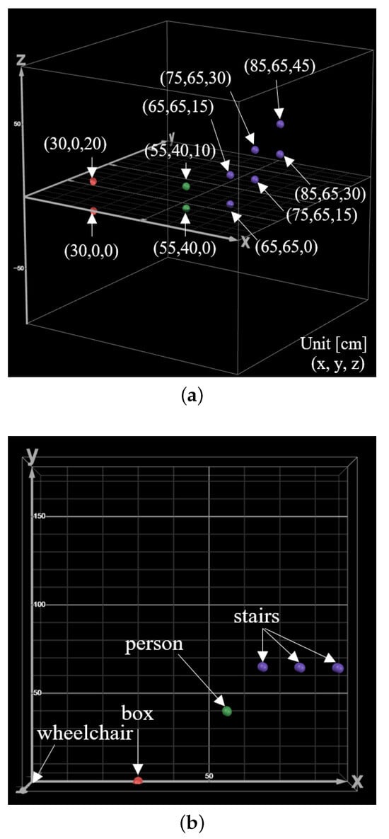
Figure 25.
Results in 3D coordinates of objects detected by the laser: (a) 3D coordinate results when detecting obstacles and stairs; (b) detection points on the x-axis and y-axis.
The performance of the omnidirectional self-controlled autonomous electric wheelchair implementing the proposed method was quantitatively evaluated in terms of accuracy, reliability, and processing speed. Table 4 summarizes the results obtained from indoor and outdoor trials. The obstacle type identification accuracy using CNN was 75%, correctly classifying 15 out of 20 obstacles, including both static and dynamic objects. Stair structure recognition achieved an 80% success rate for five steps. The average processing time per frame for obstacle detection, stair recognition, and distance measurement was approximately 50 ms, demonstrating real-time operation. Furthermore, the total time required for the wheelchair to complete a predefined course, including dynamic obstacle avoidance and stair ascent/descent, was 180 s on average over three trials. The response time from detecting an obstacle to initiating avoidance maneuvers was approximately 60 ms. These results demonstrate that the proposed method provides reliable and timely performance suitable for practical autonomous navigation.

Table 4.
Performance metrics of the omnidirectional self-controlled autonomous electric wheelchair.
Previous studies using LiDAR-Inertial point cloud processing for staircase step geometry recognition and scene mapping report a measurement error of 0.9 cm [39]. In contrast, the maximum error of staircase detection using the proposed method is 0.8 cm, indicating very high measurement accuracy. Moreover, LiDAR-based methods must handle a massive amount of point cloud data, leading to increased computational load and reduced processing speed. In comparison, the proposed method achieves high accuracy with considerably faster processing, making it more suitable for real-time autonomous navigation in dynamic environments.
6. Discussion
This study demonstrates that the proposed self-controlled autonomous mobility system enables precise obstacle detection, classification, and stair climbing with high reliability. The system integrates monocular cameras, laser sensors, and convolutional neural networks (CNNs) to perform 3D spatial recognition, detect and classify obstacles, and measure their shapes. When an obstacle is detected within a predefined range, an avoidance path is automatically generated using a built-in path planning algorithm, and the system can distinguish between static and dynamic obstacles in real time through CNN-based classification. The feasibility of the system was first verified on a small-scale autonomous robot equipped with mecanum wheels, which demonstrated real-time environmental recognition and safe navigation. The same approach was then applied to an omnidirectional self-controlled electric wheelchair. The wheelchair successfully detected the number, height, and depth of stairs with a maximum error of 0.8 cm, and could perform stable stair climbing by adjusting the driving intervals of the mecanum wheels in real time. Overall, the proposed system improves mobility support by enabling precise, adaptive navigation in complex, real-world environments.
The proposed method uses green laser light, enabling high-precision detection of feature points on illuminated objects. Through binary image processing, the system was able to extract laser light with high precision even in environments where the ground was green. This indicates that the method can be applied to different types of backgrounds with consistent performance. Thus, we confirmed that the method is robust and performs well regardless of the environment.
The future directions of this study can be grouped into three main areas. First, we aim to apply CNNs to detect laser beams themselves, rather than obstacles, in camera images. Since laser reflections vary with surface color, reflectivity, and ambient lighting, training a CNN to recognize these variations is expected to achieve robust and accurate laser detection, thereby enabling precise 3D spatial recognition. Second, we are developing a SLAM system for multiple autonomous electric wheelchairs. By integrating data from inertial measurement units (IMUs) and motor encoders, each wheelchair can independently estimate its position and trajectory, map its environment, plan routes, and share information with other units, forming a distributed navigation framework. Third, we are advancing sensor fusion research by integrating additional sensing modalities to improve obstacle detection. For example, obstacles located around corners or in blind spots—undetectable by cameras—can be identified using frequency-modulated continuous wave (FMCW) radar. By combining radar data with camera and laser measurements, a highly accurate perception system that fuses visual, spatial, and reflective information can be constructed.
Applications can also be envisioned in the agricultural domain. For example, a study demonstrates the development of a low-cost, modular autonomous vehicle capable of accurately selecting and sowing seeds [40]. This highlights the potential of autonomous robots to improve efficiency and reduce labor in agricultural processes. Incorporating the proposed method for spatial recognition of objects could further enhance the feasibility and effectiveness of such autonomous agricultural systems.
Despite these technical achievements, potential limitations must be acknowledged for practical deployment. Although the system demonstrates high accuracy, robust performance under controlled conditions, and real-time operation, user acceptance may pose a challenge. The system could be less intuitive or comfortable for some users, potentially limiting widespread adoption. Additionally, environmental factors such as smoke, heavy rain, or other adverse weather conditions can affect sensor performance, reducing reliability in such scenarios. Nevertheless, the system remains cost-effective and safe in typical indoor and controlled outdoor environments. Addressing these challenges will be essential to maximize the societal impact of inclusive mobility solutions.
Author Contributions
Conceptualization, methodology, software, validation, formal analysis, and investigation, H.M.; resources, data curation, writing—original draft, writing—review and editing, visualization, supervision, project administration, and funding acquisition: H.K. and T.I. All authors have read and agreed to the published version of the manuscript.
Funding
This research received no external funding.
Data Availability Statement
The original contributions presented in this study are included in the article. Further inquiries can be directed to the corresponding author.
Acknowledgments
We would like to express our sincere gratitude to Access Engineering Co., Ltd. for their valuable contributions to this research. Their support and expertise were instrumental in the completion of this study.
Conflicts of Interest
The authors declare no conflicts of interest. The funders had no role in the design of the study; in the collection, analyses, or interpretation of data; in the writing of the manuscript; or in the decision to publish the results.
References
- Liu, Y.; Wang, S.; Xie, Y.; Xiong, T.; Wu, M. A Review of Sensing Technologies for Indoor Autonomous Mobile Robots. Sensors 2024, 24, 1222. [Google Scholar] [CrossRef] [PubMed]
- Sommer, D.; Kasbauer, J.; Jakob, D.; Schmidt, S.; Wahl, F. Potential of Assistive Robots in Clinical Nursing: An Observational Study of Nurses’ Transportation Tasks in Rural Clinics of Bavaria, Germany. Nurs. Rep. 2024, 14, 267–286. [Google Scholar] [CrossRef]
- Zohaib, M.; Pasha, S.; Javaid, N.; Iqbal, J. IBA: Intelligent Bug Algorithm—A Novel Strategy to Navigate Mobile Robots Autonomously. Commun. Technol. Inf. Secur. Sustain. Dev. IMTIC 2013 2014, 414, 291–299. [Google Scholar]
- Puriyanto, R.; Mustofa, A. Design and Implementation of Fuzzy Logic for Obstacle Avoidance in Differential Drive Mobile Robot. J. Robot. Control JRC 2024, 5, 132–141. [Google Scholar] [CrossRef]
- Ha, V.; Thuong, T.; Truc, L. Trajectory tracking control based on genetic algorithm and proportional integral derivative controller for two-wheel mobile robot. Bull. Electr. Eng. Inform. 2024, 13, 2348–2357. [Google Scholar] [CrossRef]
- Turhanlar, E.; Ekren, Y.; Lerher, T. Autonomous mobile robot travel under deadlock and collision prevention algorithms by agent based modelling in warehouses. Int. J. Logist. Res. Appl. 2024, 27, 1322–1341. [Google Scholar] [CrossRef]
- Molfino, R.; Cepolina, E. Robots trends and megatrends: Artificial intelligence and the society. Ind. Robot. Int. J. Robot. Res. Appl. 2024, 51, 117–124. [Google Scholar] [CrossRef]
- George, A.; George, S.; Baskar, T. Artificial Intelligence and the Future of Healthcare: Emerging Jobs and Skills in 2035. Partners Univers. Multidiscip. Res. J. PUMRJ 2024, 1, 1–21. [Google Scholar]
- Yevsieiev, V.; Uskov, S. Development of the Layout Concept of a Small-Dimensioned Mobile Robot with Increased Accessibility. In Scientific Research in the Conditions of Rapid Development of Information Technologies, Proceedings of the XXXI International Scientific and Practical Conference, Helsinki, Finland, 17–19 July 2024; International Scientific Unity: Helsinki, Finland, 2024; pp. 33–37. [Google Scholar]
- Luo, K.; Yu, H.; Chen, X.; Yang, Z.; Wang, J.; Cheng, P.; Mian, A. 3D point cloud-based place recognition: A survey. Artifcial Intell. Rev. 2024, 57, 83. [Google Scholar] [CrossRef]
- Shah, H.; Karlsen, T.; Solberg, M.; Hameed, A. An efficient and lightweight multiperson activity recognition framework for robot-assisted healthcare applications. Expert Syst. Appl. 2024, 241, 122482. [Google Scholar]
- Teng, H.; Wang, Y.; Chatziparaschis, D.; Karydis, K. Adaptive LiDAR odometry and mapping for autonomous agricultural mobile robots in unmanned farms. Comput. Electron. Agric. 2025, 232, 110023. [Google Scholar] [CrossRef]
- Nakajima, M.; Fukui, K.; Tanaka, M. Semi-Autonomous Stair Climbing Control for an Articulated Mobile Robot by Propagating a Single Backward Wave. J. Robot. Mechatron. 2024, 36, 1339–1347. [Google Scholar] [CrossRef]
- Jia, A.; Soe, M. A Review on Sensor Technologies and Control Methods for Mobile Robot with Obstacle Detection System. Int. J. Robot. Autom. Sci. 2024, 6, 79–85. [Google Scholar] [CrossRef]
- Wang, C.; Pan, W.; Zou, T.; Li, C.; Han, Q.; Wang, H.; Yang, J.; Zou, X. A Review of Perception Technologies for Berry Fruit-Picking Robots: Advantages, Disadvantages, Challenges, and Prospects. Int. J. Robot. Agric. 2024, 14, 1346. [Google Scholar] [CrossRef]
- Menichino, A.; Serpico, A.; Vito, V.; Ariante, G.; Core, G. 3D LiDAR Sensor Characterization for Obstacle Detection in Autonomous UAS Applications. In Proceedings of the 2024 11th International Workshop on Metrology for AeroSpace (MetroAeroSpace), Lublin, Poland, 3–5 June 2024; Volume 10. [Google Scholar]
- Dona, R.; Mattas, K.; Vass, A.; Delubac, G.; Matias, J.; Tinnes, S.; Ciuffo, B. Thermal Cameras and Their Safety Implications for Pedestrian Protection: A Mixed Empirical and Simulation-Based Characterization. Int. J. Robot. Transp. Res. Rec. J. Transp. Res. Board 2024, 2679, 404–421. [Google Scholar] [CrossRef]
- Wang, Y.; Rahman, A.; Rashid, F.; Razali, M. Tackling Heterogeneous Light Detection and Ranging-Camera Alignment Challenges in Dynamic Environments: A Review for Object Detection. Sensors 2024, 24, 7855. [Google Scholar] [CrossRef]
- Zhang, J.; Zhang, F.; Kuang, S.; Zhang, L. NeRF-LiDAR: Generating Realistic LiDAR Point Clouds with Neural Radiance Fields. Proc. AAAI Conf. Artif. Intell. 2024, 38, 7178–7186. [Google Scholar] [CrossRef]
- You, Y.; Phoo, C.; Diazruiz, C.; Luo, K.; Chao, W.; Champbell, M.; Hariharan, B.; Weinberger, K. Better Monocular 3D Detectors with LiDAR from the Past. arXiv 2024, arXiv:2404.05139. [Google Scholar] [CrossRef]
- Kurbis, G.; Kuzmenko, D.; Skulskiy, B.; Mihailidis, A.; Laschowski, B. StairNet: Visual recognition of stairs for humanrobot locomotion. Kurbis Et Al. BioMedical Eng. OnLine 2024, 23, 20. [Google Scholar] [CrossRef]
- Zhang, A.; Eranki, C.; Zhang, C.; Park, J.; Hong, R.; Kalyani, P.; Kaiyanaraman, L.; Gamare, A.; Bagad, A.; Esteva, M.; et al. Towards Robust Robot 3D Perception in Urban Environments: The UT Campus Object Dataset. IEEE Trans. Robot. 2024, 40, 3322–3340. [Google Scholar] [CrossRef]
- Zhao, H.; Tang, Z.; Li, Z.; Dong, Y.; Si, Y.; Lu, M.; Panoutsos, G. Real-time object detection and robotic manipulation for agriculture using a YOLO-based learning approach. In Proceedings of the 2024 IEEE International Conference on Industrial Technology (ICIT), Bristol, UK, 25–27 March 2024. [Google Scholar]
- Totoki, S.; Akamine, S.; Kobayashi, S.; Itami, T.; Yoneyama, J. Real-time dynamic obstacle detection using a line laser and camera in the dark. In Proceedings of the AROB 27th, Online, 25–27 January 2022. [Google Scholar]
- Shafiq, U.; Imran, A.; Maznoor, S.; Majeed, H.; Ahmed, B.; Khan, I.; Mohamed, A. Real-time navigation of mecanum wheel-based mobile robot in a dynamic environment. Contents List. Available Sci. 2024, 10, e26829. [Google Scholar] [CrossRef]
- Zhou, L.; Lannan, N.; England, C.; Fan, G. A Virtual Mecanum Wheeled Robot ROS Simulator for Multi-view and Self-Following Motion Capture. Int. J. Mech. Eng. Robot. Res. 2024, 13, 522–529. [Google Scholar] [CrossRef]
- Li, L.; Schulze, L.; Kalavadia, K. Promising SLAM Methods for Automated Guided Vehicles and Autonomous Mobile Robots. Procedia Comput. Sci. 2024, 232, 2867–2874. [Google Scholar] [CrossRef]
- Li, Y.; Shen, H.; Fu, Y.; Wang, K. A method of dense point cloud SLAM based on improved YOLOV8 and fused with ORB-SLAM3 to cope with dynamic environments. Expert Syst. Appl. 2024, 255, 124918. [Google Scholar] [CrossRef]
- Lee, K.; Kim, Y.; Park, H. Shape Memory Alloy-Based Reactive Tubular (SMART) Brake for Compact and Energy-Efficient Wearable Robot Design. ACS Appl. Mater. Interfaces 2024, 16, 8974–8983. [Google Scholar] [CrossRef] [PubMed]
- Huebner, L.; Warmbein, A.; Scharf, C.; Schroeder, I.; Manz, K.; Rathgeber, I.; Gutman, M.; Bieblf, J.; Klamt, A.; Huber, J.; et al. Efects of robotic-assisted early mobilization versus conventional mobilization in intensive care unit patients: Prospective interventional cohort study with retrospective control group analysis. Crit. Care 2024, 28, 112. [Google Scholar] [CrossRef]
- Pajonk, A.; Navarro, A.; Knaack, U.; Blum, U. Additive manufacturing with varying material properties of thermosetting reactive polymers: A framework and comparison of different modes for implementing material transitions. Archit. Sci. Rev. 2024, 68, 81–93. [Google Scholar] [CrossRef]
- Zhang, S.; Luo, Z.; Yang, L.; Teng, F.; Li, T. A survey of route recommendations: Methods, applications, and opportunities. Inf. Fusion 2024, 108, 102413. [Google Scholar] [CrossRef]
- Zhou, X.; Zhang, Z.; Liang, X.; Su, M. POI Route Recommendation Model Based on Symmetrical Naive Bayes Classification Spatial Accessibility and Improved Cockroach Swarm Optimization Algorithm. Symmetry 2024, 16, 424. [Google Scholar] [CrossRef]
- Chung, J.; Fayyad, J.; Younes, Y.; Najjaran, H. Learning team-based navigation: A review of deep reinforcement learning techniques for multi-agent pathfnding. Artifcial Intell. Rev. 2024, 57, 41. [Google Scholar] [CrossRef]
- Kamil, S.; Szabolcsi, R. Enhancing Mobile Robot Navigation: Optimization of Trajectories through Machine Learning Techniques for Improved Path Planning Efficiency. Mathematics 2024, 12, 1787. [Google Scholar] [CrossRef]
- Suetsugu, M.; You, S.; Serikawa, S. Obstacle Detection and Shape Recognition Method for Mobile Robots Using Line Laser and Camera. In Proceedings of the IIAE Annual Conference 2019, Taipei, Taiwan, 5–9 September 2019. [Google Scholar]
- Zohaib, M.; Pasha, S.M.; Javaid, N.; Pasha, S.; Salaam, A.; Iqbal, J. An Improved Algorithm for Collision Avoidance in Environments Having U and H Shaped Obstacles. Stud. Inform. Control 2014, 23, 97–106. [Google Scholar] [CrossRef]
- Leong, P.; Ahmad, N. LiDAR-Based Obstacle Avoidance with Autonomous Vehicles: A Comprehensive Review. IEEE Access 2024, 12, 164248–164261. [Google Scholar] [CrossRef]
- Liu, Y.; Wei, Y.; Wang, C.; Wu, H. An Environment Recognition Algorithm for Staircase Climbing Robots. Remote Sens. 2024, 16, 4718. [Google Scholar] [CrossRef]
- Hassan, M.; Ullaha, M.; lqbal, J. Towards autonomy in agriculture: Design and prototyping of a robotic vehicle with seed selector. In Proceedings of the International Conference on Robotics and Artificial Intelligence (ICRAI) 2016, Stockholm, Sweden, 16–21 May 2016. [Google Scholar]
Disclaimer/Publisher’s Note: The statements, opinions and data contained in all publications are solely those of the individual author(s) and contributor(s) and not of MDPI and/or the editor(s). MDPI and/or the editor(s) disclaim responsibility for any injury to people or property resulting from any ideas, methods, instructions or products referred to in the content. |
© 2025 by the authors. Licensee MDPI, Basel, Switzerland. This article is an open access article distributed under the terms and conditions of the Creative Commons Attribution (CC BY) license (https://creativecommons.org/licenses/by/4.0/).