Abstract
Due to the unique structural characteristics of loess, the strength of loess is significantly influenced by the water content. Therefore, different support parameters should be used for loess tunnels constructed in different water content strata. This paper takes the Fengshouling Tunnel as a case study, studying the reasonable primary support parameters under different water contents using the surrounding rock strength test, on-site monitoring, and numerical simulation software analysis. The research findings indicate that the strength of the surrounding rock is functionally related to its water content, with the cohesive force c exhibiting an exponential relationship and the angle of internal friction φ showing a linear relationship, and that the cohesive force c is more affected by changes in water content than the internal friction angle φ. The crown settlement of the loess tunnel exceeds the horizontal convergence, and the deformation behavior can be categorized into three distinct stages: rapid growth, continuous growth, and slow growth. Concurrently, the primary support structure mainly bears compressive stress. On the basis of considering structural safety and engineering economy, for tunnels with a general water content (10~17%), it is recommended to use I18 steel ribs spaced 60 cm apart and C25 shotcrete with a 24 cm thickness; for high water content (17~25%), it is recommended to use I20a steel ribs, also spaced 60 cm apart, complemented by C25 shotcrete increased to a 26 cm thickness; for situations with an extremely high water content (≥25%), it is recommended to reinforce the surrounding rock with curtain grouting and use steel ribs with the same 60 cm spacing, along with C25 shotcrete maintained at a 26 cm thickness. This paper proposes reasonable support parameters for loess tunnels applicable to different water contents. These results can provide guidance and specific reference for loess tunnels under different water content strata.
1. Introduction
Under the requirements of the “Belt and Road” initiative and the “transportation power” strategy, the central and western regions of China, where loess is widely distributed, are experiencing continuous improvements in transportation infrastructure, the number of loess tunnels is growing, and rich and valuable engineering experience has been accumulated []. At the same time, given the structural characteristics of vertical joint development, porosity and loose structure, the engineering characteristics of being prone to collapse and peeling when encountering water lead to the occurrence of safety and stability problems [,,,], such as rock collapse and deformation intrusion, and the damage to surface buildings caused by unstable support structures in some shallow buried loess tunnels [,,,,], has attracted widespread attention, as shown in Figure 1.

Figure 1.
Engineering problems during the tunnel construction stage.
In order to solve the engineering problems caused by the instability of the support structure during the construction of loess tunnels, Luo relied on a large number of loess tunnel projects to study the mechanical characteristics of the support structure. He used vibrating wire sensors to analyze the deformation and mechanical state of the support structure, and proposed a new type of primary support combination structure with a steel rib, shotcrete, and a locking foot anchor bolt (pipes), which accelerated the construction progress, reduced the construction cost, and ensured the safety and stability of loess tunnels [,,,,]. Some experts and scholars have analyzed the deformation of the rock surrounding loess tunnels through on-site testing and numerical simulation techniques, discovered the deformation laws of the surrounding rock at different construction stages, and pointed out the key processes that affect the deformation of the surrounding rock [,,,,]. These studies provided important construction references for loess tunnels, and their achievements are widely applied in highway and railway loess tunnel engineering.
With the deepening understanding of the structural characteristics of loess, engineers have recognized that the stability of loess is intricately linked to its water content [,]. Due to its unique structural morphology and physical–mechanical properties, loess exhibits high sensitivity to water. Research on support structures alone cannot meet the needs of tunnel engineering development. Therefore, extensive research has been conducted on the strength of loess. These studies have determined that soil strength is fundamentally related to its shear strength [,], and variations in water content are the primary factors influencing the deformation and strength characteristics of loess [,,,]. Zhao and Zhang found, through their study on the shear strength of loess, that the strength of loess decreases significantly with increasing water content, and the influence of water content on cohesion c is greater than that of internal friction angle φ [,]. In order to study the relationship between tunnel stability and surrounding rock moisture content, Li and Shao conducted a large-scale test on collapsible loess at a site with existing tunnels, marking the first such test domestically and internationally, studied the mechanism of the impact of loess collapsibility deformation on tunnel support structures, and revealed the collapsibility process of loess and the variation of stresses in the support structure under long-term immersion [,,]. Liang and Li took the water-rich highway and railway loess tunnels in Ningxia Province as the engineering background, proposed a predictive function model for surrounding rock deformation, compared large deformation control methods through numerical simulation, and conducted in situ control effect tests [,]. The deformation behaviors and stress are different for loess tunnels under different water content strata. Although the above studies have proposed some measures and provided some help for follow-up study, there is no research on support parameters, especially on reasonable support parameters for loess tunnels with different water content strata, resulting in unnecessary economic waste.
Therefore, to improve the economy while ensuring safety and stability, this paper studies the deformation behavior and the mechanical characteristics of the support structure under natural water content in Fengshouling Tunnel, combines the on-site test results with indoor experiments results and numerical simulations, and studies the mechanical characteristics of supporting structures under different water contents. This research can provide a basis and guidelines about the selection of support parameters for loess tunnels under different water contents.
2. Introduction of Engineering Project
2.1. Tunnel Situations
The Fengshouling Tunnel belongs to the loess highway tunnel group of the Xixian County-–Jixian County section of the Huhehaote–Beihai National Expressway. As a four-lane and two-hole project, it is located in the southwest of Shanxi Province, as shown in Figure 2. The lengths are 2598 m from ZK89+462 to ZK92+060 for the left hole, and 2590 m from YK89+460 to YK92+050 for the right hole, with an excavation height of 9.65 m and an excavation span of 12.38 m. The maximum depth of the two lines is about 158.4 m. According to the relevant provisions of the Specifications for Design of Highway Tunnels Section 1 Civil Engineering (JTG 3370.1-2018) [] and the Guidelines for Design of Highway Tunnel (JTG/T D70-2010) [], combined with the geological exploration results of the Fengshouling Tunnel, the entire tunnel passes through grade V surrounding rock, and the surrounding rock has poor self-stabilization ability, easy excavation, and difficult tunnel formation. Table 1 displays the support parameters for the tunnel.
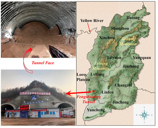
Figure 2.
The location and the tunnel face of Fengshouling Tunnel.

Table 1.
Support parameters of Fengshouling Tunnel.
2.2. Surrounding Rock Strength
Direct Shear Test
Surrounding rock parameters of Fengshouling Tunnel were obtained through indoor experiments, and the relationship between strength parameters of loess and water content was studied. Figure 3 displays the experimental setup and the prepared samples, while the outcomes of the direct shear tests are presented in Table 2.
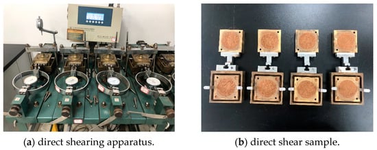
Figure 3.
Direct shear test.

Table 2.
Direct shear test results.
Research results are based on water content and loess strength parameters [,,,], exponential and linear functions are used to fit the relationship, and the fitting equations are presented in Table 3, with the corresponding fitting relationships depicted in Figure 4.

Table 3.
Function of strength parameters and water content.
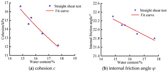
Figure 4.
Test results of loess strength parameters.
Table 3 shows that the correlation coefficients for both the exponential and the linear functions are identical, each measuring 0.93, indicating that the equations in Table 3 can effectively represent the functional relationship between the strength characteristics of loess and its water content.
According to the in situ soil geological survey data,
where Gs is the specific gravity of soil particles, e is the pore ratio, w denotes the average natural water content. Sr is the degree of saturation, wsr is the saturated water content expressed as a percentage, msr is the mass of water in saturated soil in grams; and ms is the mass of soil particles in grams.
Based on the calculated saturated water content wsr and the relationships between water content and the strength parameters of the surrounding rock, we determined the following values for the saturated state: cohesion c is 4.6 kPa, and the internal friction angle φ is 20.2°. To find the median water content, we calculated the median value between the saturated water content and the natural water content, resulting in a median water content of 21.5%. At this median water content, the cohesion c is 8.1 kPa, and the internal friction angle φ is 21.1°.
2.3. Compressive Modulus Es and Deformation Modulus E0
The natural water content compressive modulus Es was measured to be 29.5 MPa using the WG-type single-lever consolidation instrument. Based on the research results for soil mechanics [,], the deformation modulus E0 and compression modulus Es follow the following functional relationship:
where β represents the soil parameters, β = 1−2μK0, 0 ≤ β ≤ 1, μ represents the Poisson’s ratio, μ = K0/(1+ K0), and K0 represents the static side pressure coefficient.
E0 = β·Es = (1−2μK0)·Es
According to the specifications, it can be shown that β for clayey loess takes values in the range of 1.6 to 2.8 [], and the deformation modulus E0 of the surrounding rock under natural water content can be obtained as 24.7 MPa by substitution. According to the regularity test of compression modulus Es and water content w, the compression modulus Es under median water content was 20.2 MPa, and the compression modulus Es under saturated water content was 13.4 MPa. Substituted into Equation (3), the deformation modulus E0 under median water content was 16.9 MPa, and the deformation modulus E0 under saturated water content was 11.2 MPa.
According to the technical specifications for the classification of loess water content [], the water content of loess can be divided into low water content (w < 10%), general water content (10% ≤ w < 17%), high water content (17% ≤ w < 25%), and extremely high water content (w > 25%). This research indicates that the correlation between the shear strength and the water content of loess is such that within the 10–17% water content range, variations in water content have a minimal effect on the strength of loess. Nonetheless, once the water content surpasses this threshold, the shear strength of loess becomes significantly affected by changes in water content. In particular, when the water content surpasses 25%, it is difficult for the loess tunnel face to self-stabilize, and additional measures need to be taken to pre-reinforce the surrounding rock.
Therefore, taking into account the test outcomes for the surrounding rock at Fengshouling Tunnel, three different rock strength parameters with natural water content of 16.1%, median water content of 21.5%, and saturated water content of 26.9% are selected to represent rock strength parameters under general water content, high water content and extremely high water content, respectively.
By adjusting the water content w and combining it with relevant specifications [], the deformation modulus E0, cohesion c, internal friction angle φ, soil density γ and other surrounding rock parameters under different water contents are obtained, as shown in Table 4.

Table 4.
Surrounding rock parameters at different water contents.
3. On-Site Test of Mechanical Characteristics
3.1. Test Contents
According to the water content test for the surrounding rock of Fengshouling Tunnel, the mechanical behavior tests of the support structure under general water content were conducted within the range of mileage pile ZK90+041~ZK90+071, where the deformation monitoring sections are spaced every 15 m. Among these, the deformation measurement points of the surrounding rock were installed after the completion of the steel frame construction, and the deformation measurement of the surrounding rock began after the completion of the shotcrete construction. The entire line was excavated by the method of three-bench seven step, as shown in Figure 5.

Figure 5.
Schematic diagram of tunnel excavation method and measurement point layout.
The test section, ZK90+056, was selected for the monitoring of mechanical characteristics of supporting structures. According to the research findings of Luo [], total station free standing to edge measurement (RDM) was utilized as the method for measuring rock deformation, which included crown settlement and horizontal convergence. Highly sensitive and stable steel string sensors were utilized to measure the surrounding rock pressure, as well as the stresses in other supporting structures. The deformation measurement points and stress monitoring measurement points are presented in Figure 5.
3.2. On-Site Monitoring Results Analysis
3.2.1. Deformation of Surrounding Rock
The deformation test results in sections ZK90+041, ZK90+056, and ZK90+071 are shown in Table 5.

Table 5.
Deformation results of monitoring sections.
According to Table 5, the maximum vertical settlement is located at the crown (0), and the deformation value in section ZK90+056 is larger than those in the other sections. Therefore, section ZK90+056 was selected as the typical section for surrounding rock deformation analysis. The deformation temporal curve of the surrounding rock in section ZK90+056 is shown in Figure 6.
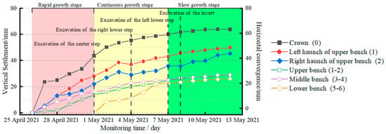
Figure 6.
Surrounding rock deformation in section ZK90+056.
The deformation curve trend is consistent according to Figure 6, and the curves consist of a rapid growth stage, a continuous growth stage, and a slow growth stage. These deformation stages exhibit similar durations, of 6 days, 6 days, and 5 days, respectively. Based on the excavation steps, the stage of invert excavation corresponds to a significant reduction in the deformation of the surrounding rock. It is clear that constructing the invert is beneficial for controlling the deformation of loess tunnels. The deformation values reveal that the settlement at the crown exceeds the horizontal convergence. Due to the loess’s creep nature, the deformation trend in loess tunnels fails to reach a stable state, which is different from that observed in rock tunnels. Therefore, the secondary lining should be constructed after the deformation has reached a stable state to prevent congenital damage to the secondary lining.
3.2.2. Surrounding Rock Press
The surrounding rock press test results in section ZK90+056 are shown in Figure 7. According to the on-site burial situation, 11 measuring points were set up, but unfortunately, a total of four measuring points were damaged at the invert, and we could not observe the changes in surrounding rock pressure at the invert.

Figure 7.
Surrounding rock press in section ZK90+056.
According to the distribution in Figure 7a, the pressure value in the test section is not large and is evenly distributed, with the exception of the right arch foot (No. 6 measuring point), where the value is 0.065 MPa, and with the other points generally not exceeding 0.05 MPa overall. Further analyzing the variation law, as shown in Figure 7b, we can see that the temporal curve consists of three stages: rapid growth stage, continuous growth stage, and stable stage. The pressure increased rapidly when the upper bench was excavated, as indicated in the pink domain. Upon excavating the invert, there was a further increase in pressure, although the trend of this increase was not substantial, as indicated in the yellow domain. When the secondary lining was applied, the pressure fluctuated due to the influence of concrete hydration heat. As the age and strength of the shotcrete increased, the pressure tended to stabilize, as indicated in the green domain.
3.2.3. Steel Rib Stress
The steel rib stress test results for section ZK90+056 are shown in Figure 8. Based on the design of the sensor and for intuitive analysis, we designated compressive stress as positive values and tensile stress as negative values.
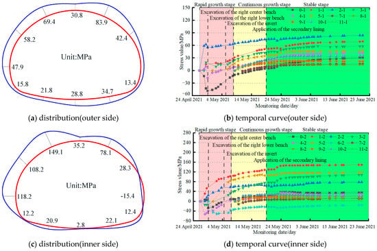
Figure 8.
Steel rib stress in section ZK90+056.
According to the stress distribution diagrams 8(a) and 8(c) for the steel rib, the steel rib predominantly bears compressive stress, with the load at the crown being greater than at other measuring points on the support structures. The stress distribution indicates that the inner side of the crown experiences higher stress than the outer side, whereas at the invert, the outer side has a greater stress value compared to the inner side. According to the stress variation curves 8(b) and 8(d) of the steel rib, the stress curves underwent three stages of change. During the interval between the excavation of the surrounding rock and the construction of the invert, there is a rapid increase in stress on the steel rib. From the excavation of the invert until the secondary lining is applied, the growth rate of stress in the steel ribs decreases compared to the rapid growth phase, clearly demonstrating that constructing the invert is effective in controlling the stress in the support structures. Following the installation of the secondary lining, stress fluctuations occurred due to the effects of concrete hydration heat, eventually reaching a stable condition. In addition, the maximum compressive stress recorded was 149.1 MPa, while the maximum tensile stress was 15.4 MPa; both values are below the yield strength of 235 MPa for the steel ribs.
3.2.4. Shotcrete Test Results
The shotcrete test results for section ZK90+056 are shown in Figure 9, and the symbol specifies the same stress as the steel rib.
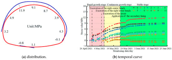
Figure 9.
Shotcrete stress in section ZK90+056.
From the stress distribution diagram 9(a) for the shotcrete, it can be seen that the shotcrete mainly bears compressive stress and that the load on the crown is greater than at other measuring points. According to the stress variation curves 9(b) of the steel rib, the stress curves underwent three stages of change, similar to the stress variation curve of the steel rib. Due to the fact that the solidification and hardening of sprayed concrete is a time-dependent process, its strength and durability develop gradually over time. Therefore, the stress of shotcrete is always in the growth stage. The stress in the shotcrete stabilizes following the application of the secondary lining, fluctuates slightly under the influence of the hydration heat of the secondary lining concrete, and then reaches a stable state. In addition, the maximum measuring point for compressive stress is located 30° to the left of the crown top, with a value of 11.9MPa. This is below the designed tensile strength of 13.5 MPa for C25 shotcrete. The maximum measuring point for the tensile stress is located 30° to the left of the invert, with a value of 0.8MPa, which is less than the design tensile strength of 1.27MPa.
3.3. Evaluation of Design Support Parameters
Based on the on-site monitoring results, the tunnel deformation and support structure stress monitoring results of section ZK90+056 are summarized as listed in Table 6. The rationality of the original design parameters of the support structure is analyzed, and the safety of the tunnel support structure is evaluated.

Table 6.
Safety evaluation of ZK90+056 section support structure.
The monitoring results show that the maximum settlement of the crown of the monitoring section is 64 mm, and the maximum horizontal convergence is 32.7 mm. These values are much smaller than the design reserved deformation of 150 mm. The maximum compressive stress of the steel rib is located at the inner left arch foot, with a compressive stress value of 149.1 MPa, accounting for 63.4% of the yield strength of the steel rib. The maximum tensile stress is located at the outer right arch foot, with a tensile stress value of 15.4 MPa, accounting for only 6.5% of the yield strength of the steel rib. The maximum compressive stress of shotcrete is located at 30° of the left arch waist, with a compressive stress value of 11.9 MPa, accounting for 88.1% of the design compressive strength of C25 shotcrete. The maximum tensile stress is located at the left side of the invert, with a tensile stress value of 0.8 MPa, accounting for 62.9% of the design value. Based on the above analysis, it can be concluded that the deformation of the primary support structure and the stress at each measuring point meet the safety requirements of the support structure, indicating that the support structure is safe and reliable, and has sufficient safety reserves.
4. Numerical Simulation
According to the evaluation of the support parameters of Fengshouling Tunnel, it is not difficult to find that the design strength of the support structure is much greater than the on-site engineering needs, resulting in a certain amount of economic waste, indicating that the original design support parameters are not suitable for the construction of loess tunnels in natural water content strata. Therefore, in order to obtain reasonable support parameters applicable to different water contents, based on the strength parameters of the surrounding rock of Fengshouling Tunnel under different water contents, the mechanical behavior of the support structure under different water contents is solved through Flac3D 6.0 numerical simulation software, and the comprehensive safety factor method was used to verify the mechanical responses of the three support structures under the original design support parameters. Based on construction experience and scholarly research, reasonable support parameters for loess tunnels under different water contents are proposed. It should be noted that the current design of support parameters for loess tunnels is mainly based on the principle of the most unfavorable working conditions. Therefore, the secondary lining is only used as a safety reserve and does not participate in the load. This article does not study the secondary lining.
4.1. Modeling
Due to the unique structure of loess, the stress–strain behavior of materials throughout the stress process is characterized using the Bilinear Strain–Hardening/Softening Model, and the soil is not deformable []. The elastic constitutive model was used for the primary support and the bolts. On-site observations indicate that the tunnel structure is covered by 50 m of overlying soil. Additionally, the tunnel is situated 44 m away from both the left and right boundaries, and the distance from the lower boundary to the base of the tunnel is 34 m. These dimensions are designed to mitigate the impact of boundary effects. Fixed boundaries are applied on the left and right sides, as well as the front and back sides, while the bottom of the model is constrained. The top of the model is left free for deformation. The model does not include secondary lining during the construction process. The surrounding rock is Q2 silty clay. In the modeling process, the steel rib is equivalent to shotcrete. The excavation approach is in accordance with the real-world conditions at the site. Figure 10 provides an overview of the model, and for the purpose of this paper, the simulation results of the middle section have been chosen for analysis to validate the model’s rationality.
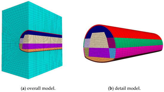
Figure 10.
Numerical simulation model diagram.
The support parameters of the numerical model are consistent with the design parameters of Fengshouling Tunnel, as listed in Table 7.

Table 7.
Support parameters of grade V.
The primary support structures consist of shotcrete and a steel rib. When conducting numerical simulations, the support structure is treated as a unified entity, with the modulus of elasticity and density of the steel rib converted to match those of the shotcrete. The calculation equations are presented in Equations (4) and (5), and the physical and mechanical parameters of the support structure post-conversion are detailed in Table 7 in this manuscript.
where E is the equivalent elasticity modulus of the primary support, Eg is the elasticity modulus of the steel rib, Ag is the cross-sectional area of the steel frame, Eh is the modulus of elasticity of the shotcrete, A is the total cross-sectional area, γ is the equivalent gravity of the initial support, γg is the gravity of the steel frame, and γh is the gravity of the shotcrete.
4.2. Simulation Analysis of Original Design Support Parameters
4.2.1. Comparison of Deformation Results
Field measurement data reveal that the settlement deformation at the crown is the predominant form of the surrounding rock deformation within the Fengshouling Tunnel. In addition, due to the length limitations of this article, the vertical settlement deformation of the crown has been chosen as the focus for analyzing the deformation of the surrounding rock in loess tunnels. Figure 11 displays the temporal settlement deformation curves at the crown measurement points under different water content conditions, as derived from the calculation results. Additionally, Figure 12 illustrates the distribution of the proportion of crown settlement deformation throughout each process.
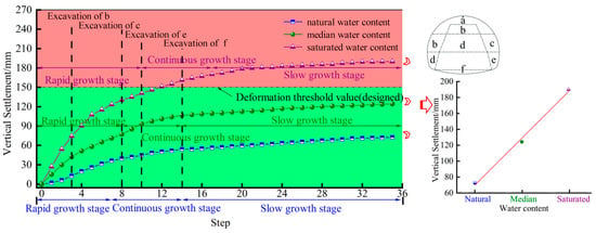
Figure 11.
Curves diagram of crown settlement deformation.

Figure 12.
Percentage distribution of crown settlement under different processes.
Figure 11 illustrates that the vertical settlement at the crown under natural water content is 72.5 mm, which is larger than the deformation measurements from the field. The reason for this is that due to the impact of on-site construction, some surrounding rock deformations could not be obtained. Therefore, it is reasonable for the simulated calculation results to be greater than the on-site-measured results. The comparison of the deformation results shows that the simulated deformation results conform to the deformation law of the surrounding rock, and this correspondence affirms the rationality of the model’s construction. In addition, the final value for the crown settlement under median water content is 124.3 mm, and this value is 189.3 mm under saturated water content. According to the allowable deformation value of 150 mm for Fengshouling Tunnel, the final value under saturated water content was larger than the deformation threshold value 150 mm, and less than the deformation threshold value of reservation deformation 250 mm under grade V []. The three deformation curves collectively demonstrate that the deformation characteristics of the surrounding rock in loess tunnels are not closely tied to water content variations, and can be represented by rapid growth stage, continuous growth stage, and slow growth stage. By analyzing the final deformation values of the surrounding rock under three different water contents, for the same level of support strength, the deformation value of the surrounding rock in the Fengshouling Tunnel increases linearly with the rise in water content within the loess strata.
According to the distribution diagram of crown settlement percentages under different stages in Figure 12, it is clear that the settlement deformation of the crown in the Fengshouling Tunnel, under different water content scenarios, predominantly takes place during the excavation phases of the upper and middle bench. These stages account for 60.5%, 62.1%, and 68.6% of the total settlement value, respectively. This suggests that strict control over the deformation of the surrounding rock is essential during the early construction stage of loess tunnels.
4.2.2. Comparison of Stress Results
According to the numerical simulation calculation results, when calculating the axial force, the bending moment of the steel rib and shotcrete, the total axial force, and the total bending moment assumed by the primary support were distributed to the steel rib and the shotcrete, according to Equations (6)–(9).
where Nh is the axial force assumed by the shotcrete (kN); N is the total axial force of the cross section in the unit length (kN); Ah is the shotcrete area; Eh is the elastic modulus of the shotcrete (kPa); Ag is the calculated section area of the steel rib (m2); Eg is the elastic modulus of the steel rib (kPa); Mh is the bending moment of the shotcrete (kN·m); Ng is the axial force assumed by the steel rib (kN); Mg is the bending moment of the steel rib (kN·m); and M is the total bending moment of the cross section in the unit length (kN·m).
The stress cloud map of the supporting structure was obtained through calculation, and the normal stress calculation method was used for each measuring point to obtain the internal force distribution of the supporting structure []. The vertical stress cloud map and internal force distribution map are shown in Figure 13.
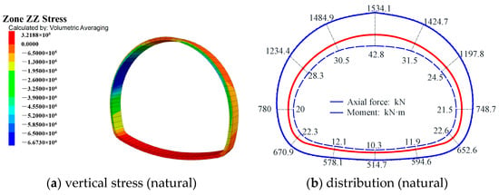
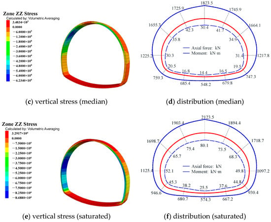
Figure 13.
The vertical stress cloud diagrams and the diagrams for the distribution of the internal force.
The internal force distribution diagram shown in Figure 13 indicates that the internal forces at the measuring point in the crown of the primary support are greater than those at the other measuring points, and they are symmetrically distributed along the tunnel’s central axis. This observation aligns with the on-site-measured data, further validating the rationality of the numerical model. Upon analysis of the internal force values, it was observed that the internal force exhibits distinct variation patterns: the axial force is highest under saturated water content and lowest under median water content, and the bending moment is smallest under natural water content, and largest under saturated water content.
4.2.3. Safety Analysis of Supporting Structures
In this paper, the comprehensive safety factor method in the Specifications for Design of Highway Tunnels (JTG/TD70−2018) was used to check and evaluate the primary support of Fengshouling Tunnel []. Its strength should conform to Equations (10)–(12). The equations are as follows:
where Khy is the compressive safety factor of the compressive strength of the shotcrete (kPa); α is the eccentric influence coefficient; Rhy is the compressive ultimate strength of the shotcrete (kPa); Kg is the compressive safety factor of the compressive and tensile strength of the steel rib (kPa); Wg is the steel rib checking calculation of the cross-section bending strength (m3); Rgy is the compressive ultimate strength of the steel rib (kPa); and Rgl is the ultimate tensile strength of steel rib (kPa).
Considering the characteristics of the internal force distribution, the axial force and bending moment of the crown structure are much greater than those of the side walls and invert when choosing the measuring points in the crown for assessing the safety factor. According to the calculation method’s specifications, the axial force is supported by both the steel ribs and the shotcrete, whereas the bending moment is supported solely by the steel ribs. The calculated safety factors for each measuring point are shown in Figure 14.
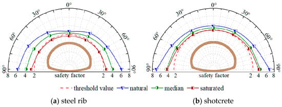
Figure 14.
Distribution diagram of safety factors.
The distribution diagram of the safety factors at different water contents shows that the axial force and bending moment are symmetrically distributed along the tunnel’s central axis, which corresponds to the distribution of the internal forces, and the minimum safety factor values are all located at the crown top measuring points. As a result, Table 8 shows the findings of the safety evaluation using the top crown measurement point as the key node.

Table 8.
Calculation results under different water contents.
As shown in Table 8, when the water content increased from 16.1% to 21.5%, the bending moment of the steel rib increased by 17.7%, the axial force of the shotcrete increased by 18.8%, the compression safety factor of the shotcrete decreased by 17.6%, the compression safety factor of the steel rib decreased by 14.8%, and the tensile safety factor of the steel rib decreased by 13.9%; when the water content rose from 21.5% to 26.9%, there was a corresponding 58.9% increase in the steel rib bending moment, the axial force of the shotcrete increased by 16.5%, the compression safety factor of the shotcrete decreased by 21.4%, the compression safety factor of the steel rib did not change, and the tensile safety factor of the steel rib changed significantly, reducing 56.7%. The compressive safety coefficient values of the shotcrete under three different water contents indicate that the shotcrete meets the safety requirements []. However, the tensile safety factor of the steel rib with a water content of 26.9% is less than 2.0, which does not satisfy the structural load-bearing requirements.
In summary, the support under natural water content has a high safety reserve, and optimization of the support parameters is achievable through the reduction in the support strength. The primary support under the median water content satisfied the structural safety requirements and did not require the optimization of support parameters. However, the steel rib compressive safety factor under saturated water content did not satisfy the safety requirements, and it was imperative to enhance the design parameters in order to ensure structural safety and stability.
4.3. Optimization Analysis of Support Parameters
4.3.1. Optimization Analysis of Support Parameters Under Natural Water Content
In response to the high support strength in the original design parameters, it was previously common to adopt measures such as changing the type of steel rib, increasing the longitudinal spacing between steel ribs, using shotcrete of a lower strength grade, or reducing the thickness of the shotcrete. By statistically analyzing the support parameters of similar projects of the same type, the recommended values of support parameters applicable to natural water-bearing formations were obtained, as shown in Table 9. The stress distribution of the support structure under different working conditions was obtained through numerical simulation, and the internal force distribution maps were obtained through conversion, as shown in Figure 15. It should be noted that based on the construction experience of similar projects, the deformation of the surrounding rock of the loess tunnel using the support parameters in the table is much smaller than the reserved deformation of 150 mm. Therefore, the deformation of the surrounding rock will not be studied here.

Table 9.
Optimizing parameters under natural water content.
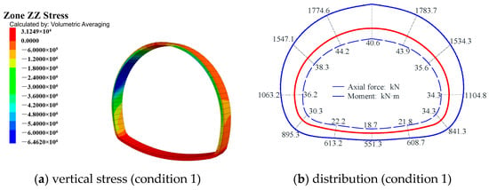
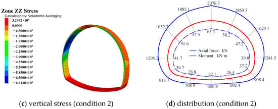
Figure 15.
The vertical stress cloud diagram and the distribution of the internal force.
The internal force distribution diagrams show that the stress at the top of the crown is greater than at other sites, and under two different working conditions, the maximum axial force is observed at the top of the crown. The crown of the structure was selected for strength analysis and verification, with the calculated safety factors for each measuring point plotted as shown in Figure 16.
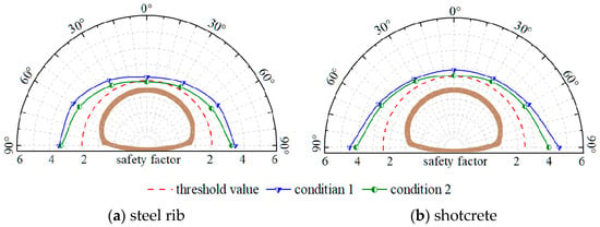
Figure 16.
Distribution diagram of safety factors.
The distribution diagram considering various conditions indicates that the safety factors exhibit a symmetrical distribution along the central axis of the tunnel when the water content is natural, and the minimum safety factor values are all located at the crown top measuring points. As a result, Table 10 shows the findings of the safety evaluation using the top crown measurement point as the key node.

Table 10.
Calculation results under natural water content.
As shown in Table 10, the safety coefficients of the compressive resistance of the shotcrete are 2.8 and 2.4, and the safety factors of condition 1 and 2 are not less than the threshold value, 2.4, of the shotcrete. The safety factors of the steel ribs are as follows: the compressive safety factors are 2.3 and 1.9, while the tensile safety factors are 4.6 and 3.2. Notably, the compressive safety factor in condition 2 is below the standard requirement of 2.0 for compressive strength in steel structures, failing to meet the optimization requirements. In summary, the optimization parameters of working condition 1 satisfied the strength verification requirements. Therefore, the support parameters under condition 1 were selected as the support structures for loess tunnels under natural water content.
4.3.2. Optimization Analysis of Support Parameters Under Saturated Water Content
Through in situ research and a literature review, it was determined that when the water content exceeds 25%, the soil will exhibit soft plasticity characteristics. Therefore, not only was it essential to enhance the support structure, but it was also necessary to bolster the surrounding rock to optimize the support parameters under saturated water content conditions. Usually, methods such as using advanced grouting small conduits (condition 1) or conducting curtain grouting on the surrounding rock (condition 2) were used to reinforce the surrounding rock. Therefore, the advanced grouting small conduit and the conducted curtain grouting adopted the equivalent principle, and the support effect was equivalent to the surrounding rock reinforcement zone (MTPRC, 2018). Figure 17 illustrates the calculation model. The specific optimization conditions and detailed calculation parameter selection are listed in Table 11 and Table 12.
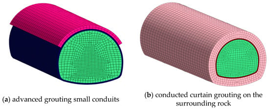
Figure 17.
Surrounding rock reinforcement tunnel model.

Table 11.
Optimizing parameters under saturated water content.

Table 12.
Parameters of surrounding rock reinforcement zone.
The surrounding rock deformation after the enhancement of the support strength clearly decreased, and the deformation value still met the deformation demand (MTPRC, 2024). Therefore, the focus of this study was on investigating the stress conditions in the support structure after its parameters were altered. The distributions of the internal forces within the support structure under different working conditions are depicted in Figure 18.
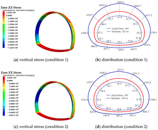
Figure 18.
The vertical stress cloud diagram and the distribution of the internal force.
The internal force distribution diagrams indicate that the stress at the top of the crown exceeds other measuring points of the support structure, and under two different working conditions, the maximum axial force was observed the top of crown. Consequently, the crown of the structure was selected for strength analysis and verification, with the calculated safety factors for each measuring point depicted in Figure 19.
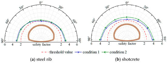
Figure 19.
Distribution of safety factors.
The distribution diagram considering various conditions indicates that safety factors exhibit a symmetrical distribution along the central axis of the tunnel when the water content is saturated, and the minimum safety factor values are all located at the crown top measuring points. As a result, Table 13 shows the findings of the safety evaluation using the top crown measurement point as the key node.

Table 13.
Calculation results under saturated water content.
As shown in Table 13, the safety coefficients of the compressive resistance of the shotcrete are 2.6 and 3.1, which are greater than the shotcrete safety threshold, and the safety factors for the steel ribs are as follows: the compressive safety factors are 1.8 and 2.1, while the tensile safety factors are 2.9 and 3.4. Notably, the compressive safety factor in condition 1 is below the standard requirement of 2.0 for compressive strength in steel structures, failing to meet the optimization requirements. In summary, the optimization parameters of working condition 2 satisfied the strength verification requirements. Therefore, the support parameters under condition 2 were selected as the support parameters for loess tunnels under saturated water content.
5. Conclusions
Based on Fengshouling Tunnel, the support parameters with grade V rock mass suitable for different water contents were investigated by the rock strength test, on-site monitoring, and numerical simulation. The results can be summarized as follows:
- (1)
- The cohesion c of the loess decreased exponentially with the water content, whereas the internal friction angle φ showed a linear correlation with the water content. Additionally, it was observed that cohesion c was more significantly influenced by changes in water content compared to the internal friction angle φ.
- (2)
- The crown settlement was greater than the horizontal convergence. The maximum deformation value was 64 mm, which is much less than the design reserved deformation. The primary support structure mainly bore the compressive stress, and the force on the crown was greater than at other sites, where it was smaller and distributed symmetrically.
- (3)
- The deformation of the surrounding rock is much smaller than the reserved deformation, and the stress value of the support structure is much smaller than the design value. The support structure has a large safety reserve and does not meet the needs of economic construction. The optimization of the support parameters can be achieved by reducing the support strength.
- (4)
- The deformation behavior under different water contents can be characterized by three stages: rapid growth, continuous growth, and slow growth. It was observed that the final settlement value at the crown increases linearly with the water content under same support strength. The surrounding rock deformation in loess tunnels predominantly occurs during the initial phase of excavation. This suggests that strict control over the surrounding rock deformation is essential during the early construction stage of loess tunnels.
- (5)
- For general water content levels ranging from 10% to 17%, the recommended support parameters consist of I18 steel ribs with a longitudinal spacing of 60 cm and C25 shotcrete with a thickness of 24 cm. For high water content levels between 17% and 25%, the suggested parameters are I20a steel ribs with the same 60 cm spacing and C25 shotcrete increased to a thickness of 26 cm. In cases of extremely high water content exceeding 25%, the surrounding rock is reinforced with curtain grouting, and the support parameters recommend I22a steel ribs with a 60 cm longitudinal spacing and C25 shotcrete with a thickness of 26 cm.
Author Contributions
Conceptualization, H.C. (Hao Chen) and Y.L. (Yanfeng Li); Methodology, Y.L. (Yanbin Luo) and J.C.; Validation, H.C. (Hui Chen); Formal analysis H.C. (Hao Chen); Resources, Y.L. (Yanbin Luo); Investigation, H.C. (Hui Chen); Data curation, L.G. and P.W.; Supervision, H.C. (Hao Chen) and Y.L. (Yanbin Luo). All authors have read and agreed to the published version of the manuscript.
Funding
The authors would like to acknowledge the financial support provided by the National Natural Science Foundation of China (Grant No. 52278394), by “ Key Research and Development Program of Shaanxi Province” (Grant No. 2024SF-YBXM-628), and by “Shaanxi Province Innovation Capability Support Plan” (Grant No. 2024RS-CXTD-42).
Institutional Review Board Statement
Not applicable.
Informed Consent Statement
Not applicable.
Data Availability Statement
The data presented in this study are available upon request from the corresponding author. The data are not publicly available due to privacy.
Acknowledgments
The authors are grateful for the comments provided by the anonymous reviewers.
Conflicts of Interest
The authors declare no conflicts of interest.
References
- Luo, Y.B.; Chen, J.X.; Shi, Z.; Li, J.Z.; Liu, W.W. Mechanical characteristics of primary support of large span loess highway tunnel: A case study in Shaanxi Province, Loess Plateau, NW China primary. Tunn. Undergr. Space Technol. 2020, 104, 103532. [Google Scholar] [CrossRef]
- Sun, W.; Liang, Q.G.; Qin, S.H.; Yuan, Y.X.; Zhang, T.J. Evaluation of groundwater effects on tunnel engineering in loess. Bull. Eng. Geol. Environ. 2021, 80, 1947–1962. [Google Scholar] [CrossRef]
- Shao, S.; Shao, S.J.; Li, J.; Qiu, B. An Analysis of Loess Tunnel Failure and Its Mechanism. Adv. Civ. Eng. 2021, 2021, 6671666. [Google Scholar] [CrossRef]
- Hong, Q.Y.; Lai, H.P.; Liu, Y.Y. Failure analysis and treatments of collapse accidents in loess tunnels. Eng. Fail. Anal. 2022, 145, 10737. [Google Scholar] [CrossRef]
- Ma, E.L.; Lai, J.X.; Xu, S.S.; Shi, X.H.; Zhang, J.; Zhong, Y.J. Failure analysis and treatments of a loess tunnel being constructed in ground fissure area. Eng. Fail. Anal. 2022, 134, 106034. [Google Scholar] [CrossRef]
- Chen, J.X.; Tian, C.P.; Luo, Y.B.; Li, Y.; Liu, W.W.; Chen, H.; Zhu, H.Y. Deformation behavior and damage characteristics of surface buildings induced by undercrossing of shallow large-section loess tunnels. Eng. Fail. Anal. 2024, 162, 108422. [Google Scholar] [CrossRef]
- Victor, H.F.; Gilson, d.F.N.G.; Andre, d.A. Probabilistic assessment of tunneling-induced building damage Comput. Geotech. 2019, 113, 103097. [Google Scholar]
- Burd, H.J.; Yiu, W.N.; Acikgoz, S.; Martin, C.M. oil-foundation interaction model for the assessment of tunnelling-induced damage to masonry buildings. Tunn. Undergr. Space Technol. 2022, 119, 104208. [Google Scholar] [CrossRef]
- Son, M.; Cording, E.J. Estimation of building damage in a 3D distorting structure to tunnel and underground excavation-induced ground movements. Tunn. Undergr. Space Technol. 2020, 97, 103222. [Google Scholar] [CrossRef]
- Mirhabibi, A.; Soroush, A. Effects of building three-dimensional modeling type on twin tunneling-induced ground settlement. Tunn. Undergr. Space Technol. 2013, 38, 224–234. [Google Scholar] [CrossRef]
- Luo, Y.B.; Chen, J.X.; Wang, H.Y.; Sun, P.L. Deformation Rule and Mechanical Characteristics of Temporary Support in Soil Tunnel Constructed by Sequential Excavation Method. KSCE. J. Civ. Eng. 2017, 21, 2439–2449. [Google Scholar] [CrossRef]
- Luo, Y.B.; Chen, J.X.; Gao, S.T.; Deng, X.H.; Diao, P.S. Stability analysis of super-large-section tunnel in loess ground considering water infiltration caused by irrigation. Environ. Earth Sci. 2017, 76, 763. [Google Scholar] [CrossRef]
- Luo, Y.B.; Diao, P.S.; Chen, J.X.; Li, D.; Guo, Y.L.; Qiao, X. New Method of Monitoring Tunnel Feet-Lock Pipe (TFP) Mechanics Using Fiber Bragg Grating (FBG). J. Test. Eval. 2020, 48, 3125–3142. [Google Scholar] [CrossRef]
- Luo, Y.B.; Chen, J.X.; Huang, P.; Tang, M.Q.; Qiao, X.; Liu, Q. Deformation and mechanical model of temporary support sidewall in tunnel cutting partial section. Tunn. Undergr. Space Technol. 2017, 61, 40–49. [Google Scholar] [CrossRef]
- Jiang, H.; Fan, X.L.; Yu, M.; Li, L.; Han, B.; Gao, S.; Zhai, C.X.; Gao, R.X.; Zhao, J.X.; Liu, L. Study on the construction deformation of a slotted shield in loess tunnels with different buried depths and large sections. Front. Earth Sci. 2023, 10, 1075928. [Google Scholar] [CrossRef]
- Zhao, Y.; He, H.W.; Li, P.F. Key Techniques for the Construction of High-Speed Railway Large-Section Loess Tunnels. Engineering 2018, 4, 254–259. [Google Scholar] [CrossRef]
- Cheng, X.S.; Liu, Y.; Liu, G.N.; Bu, Y.Y. Study on Disturbance Characteristics of Surrounding Rock During Construction of Shallow Buried Bias Loess Tunnel with Small Clear Distance. Indian Geotech. J. 2024, 54, 2421–2442. [Google Scholar] [CrossRef]
- Li, P.F.; Zhao, Y. Performance of a multi-face tunnel excavated in loess ground based on field monitoring and numerical modeling. Arab. J. Geosci. 2016, 9, 640. [Google Scholar] [CrossRef]
- Li, P.F.; Zhao, Y.; Zhou, X.J. Displacement characteristics of high-speed railway tunnel construction in loess ground by using multi-step excavation method. Tunn. Undergr. Space Technol. 2016, 51, 41–55. [Google Scholar] [CrossRef]
- Chen, F.J. Study on the Tunnel’s Modality Impact of Changes of Surrounding Rock Water Content at Loess Tunnel; Southwest Jiaotong University: Chengdu, China, 2008. [Google Scholar]
- Yue, J.P.; Liang, Q.G.; Zhang, T.J.; Fan, T.C. Research on mechanical response and time-space distribution of supporting structure of deep-buried tunnel in naturally water-rich loess. Tunn. Undergr. Space Technol. 2024, 147, 105688. [Google Scholar] [CrossRef]
- Jefferson, I.; Ahmad, M. Formation of Artificial Collapsible Loess; Geo-Denver: Aurora, CO, USA, 2007. [Google Scholar]
- Zhang, Y.J.; Wang, X.; Liang, Q.G.; Jiang, D.J.; Ma, X.M. Development of model test similar material of collapsible loess. Chin. J. Rock Mech. Eng. 2013, 32, 4019–4024. [Google Scholar]
- Bishop, A.W.; Alpan, I.; Blight, G.E.; Donald, I.B. Factors controlling the shear strength of partly partly saturated soils. In Proceedings of the American Society of Civil Engineers Research Conference on Shear Strength of Cohesive Soils, Boulder, CO, USA, 13–17 June 1960; pp. 503–532. [Google Scholar]
- Fredlund, D.G.; Morgenstern, N.R.; Widger, R.A. The shear strength of unsaturated soils. Can. Geotech. J. 1978, 15, 313–321. [Google Scholar] [CrossRef]
- Fredlund, D.G.; Xing, A.; Fredlund, M.D.; Barbour, S.L. The relationship of the unsaturated soil shear strength to the soil-water characteristic curve. Can. Geotech. J. 1996, 33, 440–448. [Google Scholar] [CrossRef]
- Donald, I.B. Shear strength measurements in unsaturated non-cohesive soils with negative pore pressures. In Proceedings of the 2nd Australia—New Zealand Conference on Soil Mechanics and Foundation Engineering, Christchurch, New Zealand, January 1956; pp. 200–204. [Google Scholar]
- Zhang, H.L.; Zhang, M.; Li, Z.P. The study of water content influence on unsaturated soil shear strength by test. J. Shijiazhuang Railw. Inst. 2001, 4, 30–33. [Google Scholar]
- Zhang, M.H.; Xie, Y.L.; Liu, B.J. Analysis of shear strength characteristics of loess during moistening process. Rock Soil Mech. 2006, 7, 1195–1200. [Google Scholar]
- Li, J.; Shao, S.J.; Li, G.L.; Miao, H.C.; Lu, Z.G. Collapse deformation of loess tunnel and its effect. Chin. J. Rock Mech. Eng. 2018, 37, 251–260. [Google Scholar] [CrossRef]
- Li, J.; Shao, S.J.; Shao, S. Collapsible characteristics of loess tunnel site and their effects on tunnel structure. Tunn. Undergr. Space Technol. 2019, 83, 509–519. [Google Scholar] [CrossRef]
- Shao, S.J.; Li, J.; Li, G.L.; Wang, X.D.; Jin, B.C.; Shao, S. Field immersion tests on tunnel in large-thickness collapsible loess. Chin. J. Geotech. Eng. 2018, 40, 1395–1404. [Google Scholar]
- Liang, Q.G.; Chen, X.Y.; Liu, X.J.; Sun, W.Y. Large Deformation Control Technology of Surrounding Rock of Water-rich Loess Tunnels—A Case Study about Yulinzi Tunnel in Tianshuibao-Yonghe Part of Yinchuan- Baise Highway. Saf. Environ. Eng. 2022, 29, 55–65. [Google Scholar]
- Chen, T.M. Surface Dewatering Excavation and Soft Foundation Reinforcement Technology for Water-Rich Loess Tunnel in Dongzhi Tableland: A Case Study of Yima No. 1 Tunnel on Yinchuan-Xi’an High-Speed Railway. Tunn. Con. 2021, 41, 1015–1025. [Google Scholar]
- JTG 3370.1-2018; MTPRC (Ministry of Transport of the People’s Republic of China). Specifications for Design of Highway Tunnels. China Communications Press: Beijing, China, 2018.
- JTG/T D70-2010; Guidelines for Design of Highway Tunnel (English Version). China Communications Press: Beijing, China, 2010.
- Lu, Z.J.; Zhang, H.M.; Chen, J.H.; Feng, M. Shear Strength and Swelling Pressure of Unsaturated Soil. Chin. J. Geotech. Eng. 1992, 14, 1–8. [Google Scholar]
- Zhang, C.G.; Zhao, J.H.; Zhu, Q. Classification and Summary of Shear Strength Formulae for Unsaturated Soils. J. Archit. Civ. Eng. 2012, 29, 74–82. [Google Scholar]
- Zhang, L.J.; Wu, X.; Xie, Y.; Wu, C.L. Influence of water content and overlying pressure on shear strength of remolded expansive soil. Chin. J. Geol. Hazard Control. 2015, 26, 138–143. [Google Scholar]
- Gong, X.N. Soil Mechanics; China Construction Industry Press: Beijing, China, 2014. [Google Scholar]
- Gong, F.J. The Research of Moistening Modulus and Deformation of Loess Subsoil; Xi’an University of Architecture and Technology: Xi’an, China, 2005. [Google Scholar]
- Luo, Y.B.; Chen, J.X.; Xi, W.Z.; Zhao, P.Y.; Qiao, X.; Deng, X.H.; Liu, Q. Analysis of tunnel displacement accuracy with total station. Measurement 2016, 83, 29–37. [Google Scholar] [CrossRef]
- JTG 3372-2024; MTPRC (Ministry of Transport of the People’s Republic of China). Technical Specifications for Design and Construction of Highway Tunnels in Loess. China Communications Press: Beijing, China, 2024.
- Pan, C.S. Numerical Methods for Tunnel Mechanics; China Railway Publishing House: Beijing, China, 1995. [Google Scholar]
Disclaimer/Publisher’s Note: The statements, opinions and data contained in all publications are solely those of the individual author(s) and contributor(s) and not of MDPI and/or the editor(s). MDPI and/or the editor(s) disclaim responsibility for any injury to people or property resulting from any ideas, methods, instructions or products referred to in the content. |
© 2025 by the authors. Licensee MDPI, Basel, Switzerland. This article is an open access article distributed under the terms and conditions of the Creative Commons Attribution (CC BY) license (https://creativecommons.org/licenses/by/4.0/).