Abstract
This paper presents a fuzzy logic control strategy for synchronising the vertical lifting and positioning of a multi-actuator hydraulic system designed for a 360-ton movable platform. The primary focus is on achieving precise actuator movement coordination under uneven loading conditions without using external reference systems or high-cost sensors. A mathematical model and a simulation environment were developed in MATLAB/Simulink with Fuzzy Logic Toolbox. Four fuzzy controller variants were evaluated regarding positioning accuracy, robustness, and compliance with dynamic constraints. The results demonstrate the effectiveness of the proposed control method, particularly when using Gaussian membership functions and PROD–PROBOR fuzzy operators. The system achieved sub-millimetre synchronisation accuracy even under 20% load imbalance. This work contributes to developing decentralised, sensor-light control strategies for large-scale hydraulic systems and offers a validated foundation for future experimental implementation in the PANDA particle detector project.
1. Introduction
The foundations for the fuzzy approach were laid by Lotfi Zadeh in the 1960s [1] and constituted a generalization of classical two-valued logic. Due to their ability to model even complex systems in conditions of uncertainty and lack of complete data, fuzzy logic algorithms and methods are used in many different fields, including engineering and robotics, economics, transport, energy, and even medicine. A comprehensive review of fuzzy logic methods used in various aspects of mechanical engineering, including positioning systems, pump and turbine controllers, flow control valves and risk assessment, has been presented by Filo in [2]. One of the developing directions in practical applications is the design and research on FLC units (Fuzzy Logic Controllers). A fuzzy logic controller is usually more challenging to develop and adjust than classical PID units. However, it has the ability to significantly better compensate for disturbances and non-linearity, as well as the possibility of parameter selection and tuning based on the expert knowledge of operators or specialists. Hence, one of the most important areas of fuzzy logic applications in mechanical engineering is the control of hydraulic drives due to their characteristics. Although numerous studies apply FLCs in hydraulic systems, most approaches require external references or assume uniform loading, which limits applicability in heavy, uneven-load conditions. Moreover, many solutions rely on high-cost sensor systems. This paper addresses these challenges by proposing a fully internal synchronization method based on relative error feedback only. Research on hydraulic positioning systems usually includes the application of digital controllers with various types of valves and actuators in the form of hydraulic actuators. Proportional flow control valves are often used for this purpose. Bao et al. [3] proposed an innovative control strategy for the bucket tip position of an autonomous excavator. The research included numerical modelling and simulations conducted in Matlab and Amesim. The results indicated that the collaboration of PID and fuzzy controllers can efficiently minimize tracking errors and accurately achieve the required actuator position. Tatoglu et al. [4] carried out research on single-stage small and medium scale robotic arms. Assuming complexity and limited possibilities of system parameter acquisition, an FLC was designed to effectively control the arm, using only a single piston and a small compressor. The FLC details, experimental setup, and results of various motion profiles were discussed. Finally, the obtained efficacy was compared with a traditional PID controller. Similarly, Thomas et al. proposed a fuzzy control strategy for a highly non-linear electro-hydraulic system (EHSS) [5]. Emphasizing that the key quality parameters of such systems are accuracy and precise position control, the authors formulated a mathematical model containing a double-acting cylinder, a solenoid-operated directional control valve, a proportional flow control valve and an FLC unit. Simulation results indicated that the proposed fuzzy approach could replace the existing system by obtaining the required position faster and more accurately. In turn, Wrat et al. focused on energy efficiency and fuzzy logic-based position control of the linear actuator used in heavy earth-moving equipment [6]. The designed PID-fuzzy controller was implemented in two systems, with a typical proportional directional control valve (PDCV) and a proportional flow control valve (PFCV), respectively. The results proved that the PDCV system with the PID-fuzzy controller allowed a reduction in energy loss and an increase in hydraulic circuit efficiency.
Some more complex fuzzy logic applications include synchronization of actuator movement and tracking control. Rehman et al. [7] presented a nested-loop control design technique to synchronize motion between two actuators, such as a servo-hydraulic actuator (SHA) and an electro-mechanical actuator (EMA). The effectiveness of the proposed strategy consisted of fuzzy-logic-based position and force controllers and a feed-forward controller. the effectiveness of the proposed strategy in the Matlab/Simulink environment. The result showed significant improvement in the output-trajectory tracking performance. Do et al. invented a novel strategy of an electro-hydraulic rotary actuator trajectory-tracking control using a fractional order fuzzy PID controller [8]. The results of the Matlab and AMESim simulations, as well as real-time experiments, proved the effectiveness of the proposed approach. Moreover, Lin and Zhang [9] focused on velocity and force control of a single-rod electro-hydraulic actuator. They used fuzzy rules to improve control performance and compensate for uncertainties and non-linearities. The obtained results verified the high accuracy of both velocity and force regulation performance. Another implementation of fuzzy logic position control related to the internal combustion engine valve lift in the fully variable valve timing system (FVVT) was presented by Lu et al. [10]. Based on a classic PID controller, the authors proposed the creation of fuzzy rules for the dynamic adjustment of its parameters. Applying the fuzzy rules resulted in fast response and accurate adjustment in both constant and unsteady speed states. Also, a significant impact of the proper choice of defuzzification method on the system performance has been reported. Another example of the application of a system in fuzzy logic is the hydraulic system of variable pitch large wind turbine proposed by Guo et al. [11]. Guo demonstrated the limitations of a traditional PID controller in such an implementation. Instead, he designed a flexible structured fuzzy logic controller (FS-FLC) with a simple structure and good adaptation abilities. The obtained results confirmed the robustness and tracking accuracy of the applied solution. In turn, Nguyen et al. [12] presented an electrohydraulic series elastic manipulator with a novel variable stiffness actuator and a hybrid robust controller based on a backstepping adaptive fuzzy logic sliding mode control scheme. The proposed solution allowed the influence of harmful phenomena such as friction, leakages, bulk modulus variability, chattering and residual vibrations to be significantly reduced. Similarly, Tho et al. also proposed an adaptive, fuzzy sliding-mode controller for an electrohydraulic actuator [13] since a traditional PID controller had difficulties in obtaining accurate position control performance due to the strong nonlinearities and time-varying, unknown system parameters. A virtual prototype approach in AMESim and Matlab software was applied to evaluate the performance of the developed controller to reduce costs and time. The results showed a significant improvement in efficiency compared to the PID unit. Truong et al. [14] also decided to develop an adaptive position control system combining back-stepping sliding mode method, fuzzy logic, and a nonlinear disturbance observer. The designed FLC was intended for a 3-DOF hydraulic manipulator with considerable payload variation. Having proven stability and robustness via the Lyapunov criterion, the proposed approach exhibited effectiveness and improvement in accuracy. The proposed control strategy is well suited for practical applications where high-precision synchronized motion is required but system simplicity and cost-efficiency are essential. It is particularly applicable in heavy-load industrial platforms, where the use of laser or gyroscopic measurement systems is infeasible. However, the current approach is limited by its reliance on displacement sensors for relative error measurement and by the lack of experimental validation at this stage. Further work is needed to confirm performance under real-world conditions. Furthermore, Jin et al. solved the problem of low output accuracy of the transplanting manipulator by proposing a control method based on the fuzzy-PID strategy [15]. First, a typical PID controller was designed, and next, it was combined with a fuzzy logic theory through the Kp, Ki, and Kd parameter adaptation via the fuzzy sets. Matlab simulation results showed an over 50% decrease in the system’s response time after applying the fuzzy logic unit. In turn, Rodríguez-Pérez et al. provided a digital tool for optimising the installation of turbines through fuzzy logic [16], including the design and development of a fuzzy-logic-based solution for this purpose.
This article presents mathematical and simulation models as well as the obtained results of the positioning system of a movable platform with a heavy load using a set of multiple hydraulic actuators. The work is mainly focused on practical application. The completed task concerns a portion of work related to constructing the Panda elementary particle detector at the GSI research centre in Darmstadt, Germany [17,18]. In order to implement the set task, the usage of a computer control system based on fuzzy logic algorithms was proposed. At the current stage, the mechanical structure of the PANDA detector platform is completed, while the final design and control strategy of the vertical positioning system are still under development. The proposed solution, therefore, represents a validated simulation concept that may be adopted in the forthcoming implementation phase. The main practical contribution of this work is the implementation and validation of a synchronization method for a multi-actuator hydraulic system using a fuzzy logic controller. The approach is based on computing the relative displacement error of each actuator with respect to the moving average of all six actuators at each control step. While the control structure is based on known fuzzy logic principles, it enables decentralized, sensor-light synchronization of actuators without the need for external references or expensive hardware. This method offers a cost-effective solution tailored for large-scale, heavy-duty systems requiring precise yet robust control. This solution is advantageous since it allows us to obtain the required accuracy of a heavy-duty device’s vertical positioning without using expensive, complex hardware gyroscopic, magnetic, or laser transducers. A significant scientific contribution is also made by the comparative studies carried out with different types of membership functions and fuzzy operators of the FLC. The results may be particularly useful in area of hydraulic control system design. The remainder of this paper is organized as follows: Section 2 presents the concept and structure of the proposed system. Section 3 outlines the modeling methodology, including the fuzzy logic controller design. Section 4 describes the simulation implementation, followed by results and discussion in Section 5. Conclusions and directions for future research are summarized in Section 6.
2. Working Principle of the Proposed Positioning System
The detector is a device weighing approximately 360 tons, which must be able to move several dozen millimetres vertically from the transport position to the working position. This implies the use of small-sized hydraulic actuators operating at high working pressure, up to 70 MPa. The main difficulty of positioning results from the need to use several actuators with synchronized movement with specified maximum accelerations and speeds and with the required accuracy of extension synchronization. The analyzed system is shown in Figure 1. It consists of a frame with the necessary equipment (2) placed on a rail system (1). The total weight equals approximately tonnes. Six high-capacity carriages (3) are used to move the frame horizontally between the home and operating positions. Each carriage contains two Demag RAE/RNE crane wheels with the 600kN capacity per wheel. The whole construction must also be able to move vertically to obtain the operational position precisely, with the accuracy of mm. Furthermore, the maximum acceleration while lifting must be below m/s2 and the maximum speed must not exceed m/s. The maximum lift height is mm. A system of hydraulic cylinders (4) mounted within the carriages is proposed to fulfill this requirement.
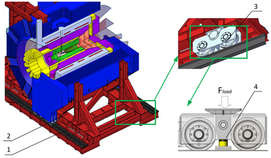
Figure 1.
The analysed system overview: 1—rails, 2—frame, 3—carriage, 4—hydraulic cylinder.
A simplified diagram of the analyzed hydraulic positioning system is shown in Figure 2. The main components of the hydraulic system are a power supply unit (1), a set of control valves (2), check-throttle valves (3) and actuators (4). The power supply unit uses a single high-pressure pump with a nominal pressure of MPa and a flow rate of dm3/min combined with an electromagnetically controlled relief valve as protection against excessive pressure increase. Proportional spool control valves, whose task is to direct the working fluid to individual actuator lines, are electromagnetically controlled using a voltage signal generated by the designed fuzzy logic system. Hydraulic actuators with a piston diameter of mm and a nominal force of kN were used as executive elements. The actuators are equipped with displacement transducers, generating input signals for the system in fuzzy logic and ball joints, eliminating lateral forces.
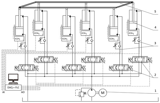
Figure 2.
Hydraulic system designed for vertical positioning: 1—hydraulic power supply, 2—proportional control valves, 3—check-throttle valves, 4—hydraulic cylinders, 5—frame, FLC—fuzzy logic controller.
3. Methodology
The applied research methodology includes formulating a mathematical model in a set of ordinary differential equations and constructing a simulation model in the Matlab/Simulink environment with the Control System Toolbox and Fuzzy Logic Toolbox modules.
3.1. Mathematical Model of Hydraulic System
The mathematical model was built by adopting a number of simplifications, including a lumped parameter fluid model with a constant value of the fluid bulk modulus, the assumption of a permanent thermal equilibrium state of the system, and taking into account only the vertical components of the loading forces. Furthermore, several phenomena were omitted, such as resistance to fluid movement in pipes, deformations of valve bodies and actuators, as well as wave effects. The input flow rate generated by a multi-piston pump having piston number z, piston stroke per revolution and rotational speed is described by the equation:
The internal leakage of the pump was assumed according to [19] as dependent on the pump design coefficients and and the supply line pressure :
Next, the supply line flow balance was formulated based on the mass conservation equation, numbering the receiver line by the i index, assuming number of receivers and return line denotation :
Under normal operational conditions, the relief valve is closed, which results in no return line flow: . An analogous balance was then written for each line between a particular control valve and actuator, assuming the base volume , active cross-sectional piston area and its current position :
The control valve characteristics were adopted based on the results of previous research [20,21], where the flow rate through the control valve throttling gap is obtained from Bernoulli’s law, assuming the throttling gap area as a function of spool position and discharge coefficient :
and the equation of spool motion, where the spool mass is , includes [20]: spring tension , viscous friction , resultant flow forces and the electromagnetic force proportional to the FLC control signal :
Finally, the equations of motion for the individual hydraulic cylinders were formulated to obtain the vertical positions against time :
The reduced mass of the i-th piston with rod is , viscous friction coefficient , load force , active piston area and return line pressure .
3.2. Fuzzy Logic Controller Model
The fuzzy logic controller model was made in a typical architecture with the output signal determination process divided into three stages, in the fuzzification, inference and defuzzification blocks, respectively. Due to the specific nature of the system operation, including the need to ensure uniform movement of all six actuators, an appropriate control strategy must be developed. The input consists of signals from the displacement transducers at the fixed control step k. Then, at each control step, the average value is determined. This allows estimation of the instantaneous position error of each actuator by determining the difference in extension from the average . Similarly, the derivative value is determined in the form of a change in value from the previous step divided by the time step value . The task of the fuzzy inference algorithm is to appropriately accelerate or decelerate the movement of the actuators so that their stroke approaches the average value. Thus, the control system has 12 input signals, the current errors and derivatives of the position errors relative to the average value, and 6 outputs as control signals for proportional control valves.
In the computational domain of each input variable, three fuzzy sets were defined using linguistic variables: N (Negative), Z (Zero) and P (Positive). The label “Z” is equivalent to “ZE” (Zero), used in the fuzzy rule table and figures for clarity. The three-level partitioning was selected based on physical system characteristics: for position error , the sets represent actuator lagging (N), synchronized (Z), and leading (P) relative to the average, with boundaries at mm (40% of the mm tolerance). For the derivative , boundaries at mm/s reflect expected synchronization dynamics during the 50 mm stroke. Five output sets (NB, NS, ZE, PS, PB) provide finer control resolution than the coarser input classification, matching the system’s high inertia where smooth control transitions are prioritized over fine error discrimination. Increasing input granularity to five or seven sets degraded performance in preliminary testing due to excessive rule switching and quadratically growing computational cost (from 9 to 25+ rules per actuator).
Example linear-type and Gaussian-type membership functions of the fuzzified parameter in the Fuzzy Logic Toolbox designer window are shown in Figure 3a and Figure 3b, respectively.
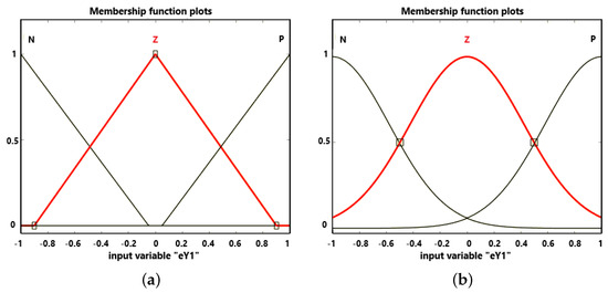
Figure 3.
Membership functions of the parameter; (a) linear-type, (b) Gaussian-type.
The system outputs are normalized values of control signal changes computed independently for all six proportional control valves. The computational domain of each output signal was divided into five fuzzy sets: NB (Negative Big), NS (Negative Small), Z (Zero), PS (Positive Small) and PB (Positive Big). For consistency, “Z” in the input sets is labeled “ZE” in the output rules (Table 1 and Figure 4), meaning “Zero.” All abbreviations are now explained in the text. Membership functions analogous to those used for the input signals were tested. Linear and Gaussian membership functions of the signal are shown in Figure 4a,b.

Table 1.
Rule database of the signal.
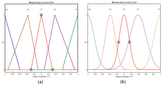
Figure 4.
Membership functions of the signal; (a) linear-type, (b) Gaussian-type.
The inference process follows the Mamdani model, using the rule database of nine rules defined for each control valve. Hence, the complete database includes 54 rules. The rules defined for the first control valve signal based on the and are shown in Table 1.
The rule base encodes intuitive synchronization logic: rules intensify corrections when error and its derivative both indicate worsening deviation (e.g., IS N AND IS N→ NB: actuator lagging and lag increasing), while diagonal rules (NB, ZE, PB) address consistent trends and off-diagonal rules (NS, PS) provide moderate corrections for conflicting signals. The central rule (Z, Z→ ZE) implements a deadband preventing chattering when synchronized. This structure, derived from hydraulic system expertise, required no manual tuning beyond initial physically-motivated design and was validated through simulation sweeps confirming monotonic control surface behavior (Figure 5).
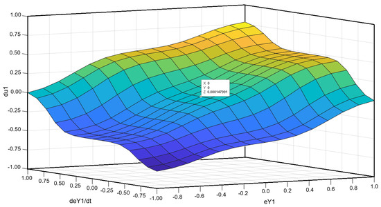
Figure 5.
Example control surface of the designed FLC with Gauss-type membership functions and PROD-PROBOR fuzzy operators.
Each created rule uses the fuzzy operator (t-norm), while the resultant aggregation of output sets requires the operators (s-norm).Within this work, two fuzzy operator types available by default in the Matlab fuzzy logic module were tested: and , respectively. In the first case, the degree of membership in the product and sum of fuzzy sets A and B is determined from the formulas: and . In the second case, the following formulas are used: and .
The last stage involves determining the output signals’ sharp (numerical) values in the defuzzification process, using the activated output fuzzy sets and the selected method. The centre of gravity (CoG, centroid) method was used following general recommendations. An example of a control surface obtained for membership functions of Gauss type and fuzzy operators is shown in Figure 5. The surface considers the normalization of input and output signals to the interval . The graph shows the zero point value, ensuring the stability of the system operation.
4. Simulation Model and Plan of Experiments
The principal part of the simulation model was built in Simulink, while the FLC was implemented using the fuzzy logic designer tool. Connections between two main block diagrams modelling the hydraulic system and the FLC are shown in Figure 6. The external load forces constituting hydraulic subsystem inputs are marked to . The following inputs are the FLC-generated proportional control valve control signals to and the pump power supply . In turn, the to output signals are current vertical positions of hydraulic cylinders, constituting inputs for the FLC.
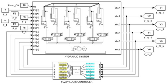
Figure 6.
Block diagram of the simulation model in Simulink.
Components of the hydraulic subsystem are shown in Figure 7, including a pump and a lumped volume of the supply line . Next, there are six parallel lines, containing control valve blocks, hydraulic cylinders and lumped volumes between them. The individual blocks are connected via pressure signals , to , , flow rate signals , to and hydraulic cylinder positions to .
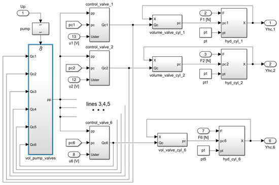
Figure 7.
Block diagram of the hydraulic subsystem in Simulink.
A plan of experiments was adopted in the first step to perform the simulations. The total load of the system was given as kN, and it was assumed that the individual actuators are loaded unevenly due to the non-uniform arrangement of equipment on the frame. The system operation was tested with the difference between the most and least loaded actuator of 5%, 10% and 20%, respectively. Each load case was tested with four fuzzy logic controllers FLC1 to FLC4 of the parameters listed in Table 2.
Table 2.
Parameters of the tested fuzzy logic controllers.
Each simulation was performed according to the scheme shown in Figure 8. Initially, the required position was assumed. Then, in the control step i, the current positions were calculated based on the signals from the measuring transducers. The determined average value of the displacement was compared with . Current error values and their derivatives were calculated for each actuator if the required position had not been reached. On their basis, FLC determined the control signals for the proportional valves . The following control step was started after the subsequent reading of signals from the displacement transducers .
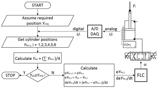
Figure 8.
Flowchart of the proposed control process using the FLC.
Considering the load cases and parameters of the fuzzy logic system, the plan of experiments included 12 simulations. To make the results comparable, equal initial conditions were assumed, including zero position of all actuators mm to mm, the required positions mm to mm and identical control signals to , being average values from the allowable range . The integration method available by default in the Simulink was used. The maximum and minimum time steps s and s and simulation time s were set. Considering the proportional control valve characteristics and the response time, the control time step was assigned to s. The control quality was assessed based on the maximum difference between the actuator positions obtained during the startup and movement as well as the integral area error ).
Based on the simulation model operation, an automated FLC-adjustment algorithm is proposed. The algorithm allows us to modify the membership function parameters to minimize the index value. For the Gaussian function, these are peak centre c and RMS width . For linear functions, the analogous parameters are peak centre c and slope coefficients . The block diagram of the algorithm assuming the Gauss membership functions is shown in Figure 9.
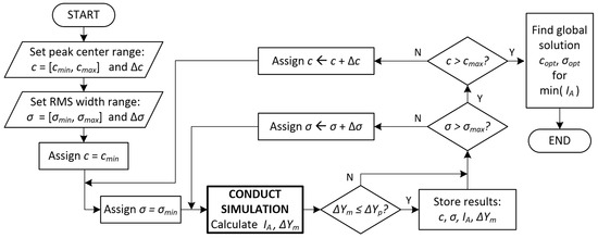
Figure 9.
Algorithm of parameter adjustment process for FLC with Gauss-type membership functions.
Initially, the allowable ranges of peak centre c and RMS width are established. Next, the domains of all parameters are uniformly searched, starting from their minimum values. The operation consists of establishing the value of c and searching the range of to find values that allow the minimum value of to be obtained. Each obtained solution is verified to ensure that the permissible difference in actuator positions during movement, , is not exceeded. After searching all the required ranges, the optimal solution is found and returned in the global range.
5. Simulation Results and Discussion
The simulation results obtained by the individual FLC systems with the maximum actuator load difference of 5% are presented in Figure 10, Figure 11, Figure 12 and Figure 13, respectively.
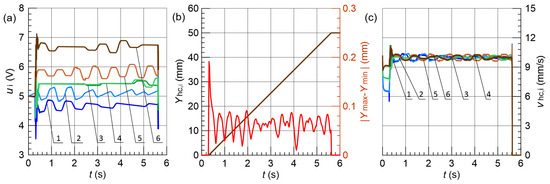
Figure 10.
Results obtained for % and FLC1; (a) control signals , (b) vertical displacement , and maximum position error , (c) hydraulic cylinder speed , 1–6—line.
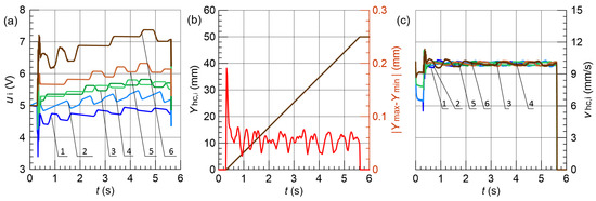
Figure 11.
Results obtained for % and FLC2; (a) control signals , (b) vertical displacement , and maximum position error , (c) hydraulic cylinder speed , 1–6—line.
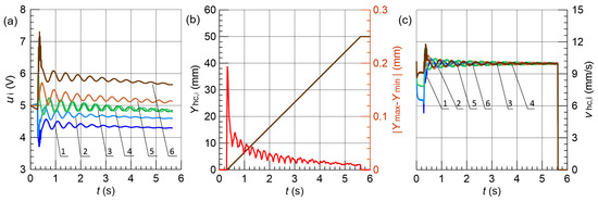
Figure 12.
Results obtained for % and FLC3; (a) control signals , (b) vertical displacement , and maximum position error , (c) hydraulic cylinder speed , 1–6—line.
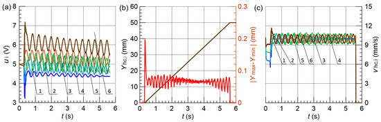
Figure 13.
Results obtained for % and FLC4; (a) control signals , (b) vertical displacement , and maximum position error , (c) hydraulic cylinder speed , 1–6—line.
FLC3 with operators and Gaussian functions achieved superior performance across multiple metrics. Beyond position accuracy, FLC3 exhibited the lowest index (30–40% reduction vs. other controllers), indicating smoother control with reduced valve wear. Critically, FLC3 maintained velocity dispersion below 0.8 mm/s and the smallest values, essential for synchronized lifting. This advantage became most pronounced under 20% load imbalance, where FLC3 maintained mm while other controllers degraded to 0.60–0.62 mm with doubled startup errors. In contrast, the most significant changes in the instantaneous speed, amounting to 2.0 mm/s, occurred in the case of the FLC4. Furthermore, FLC4 was characterized by the largest amplitude of control signal fluctuations, while both controllers having linear membership functions, FLC1 and FLC2, obtained similar results regardless of the types of applied fuzzy operators.
The results obtained with the difference in the actuators load equals 20% are presented in Figure 14, Figure 15, Figure 16 and Figure 17, respectively.
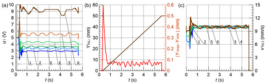
Figure 14.
Results obtained for % and FLC1; (a) control signals , (b) vertical displacement , and maximum position error , (c) hydraulic cylinder speed , 1–6—line.
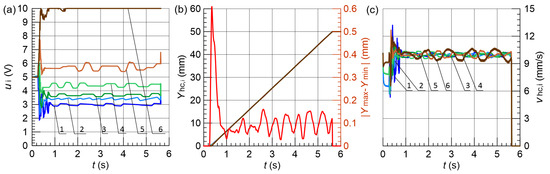
Figure 15.
Results obtained for % and FLC2; (a) control signals , (b) vertical displacement , and maximum position error , (c) hydraulic cylinder speed , 1–6—line.
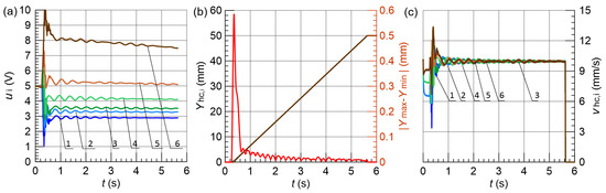
Figure 16.
Results obtained for % and FLC3; (a) control signals , (b) vertical displacement , and maximum position error , (c) hydraulic cylinder speed , 1–6—line.
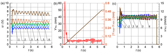
Figure 17.
Results obtained for % and FLC4; (a) control signals , (b) vertical displacement , and maximum position error , (c) hydraulic cylinder speed , 1–6—line.
Also, in this case, the best parameters were achieved by FLC3, including the maximum difference in displacements of actuators during movement not exceeding mm and the smallest position error. The FLC3 system also allowed the slightest differences in the instantaneous speed of particular actuators to be obtained.
The summary of positioning accuracies is presented in Table 3. The values obtained by the individual FLC variants are at a similar level in the case of the load difference % and %. However, with the largest considered load differences %, the FLC3 unit obtained significantly smaller error values during movement and the lowest value of the index. Hence, the recommended parameters for the FLC system are the Gaussian membership functions and the fuzzy operators − . Compared to similar studies involving hybrid fuzzy-PID controllers [3,6,15] the proposed system achieved comparable or better synchronization accuracy with a simpler control structure and without the need for precise position tracking sensors. For instance, the maximum actuator position error in our case did not exceed 0.7 mm even under 20% load imbalance, which is within the range reported in those studies. Although only linear and Gaussian membership functions were tested in this work, they represent the two most commonly used types in industrial FLC applications. Their characteristics differ significantly in terms of slope and overlap, which impacts the controller’s sensitivity. Further studies may include triangular or bell-shaped functions and increased granularity to assess the performance with more complex fuzzy partitions.
Table 3.
The obtained positioning accuracy.
Although the absolute position error of ∼0.1 mm represents only 0.2% of the 50 mm stroke, the critical performance differentiator for multi-actuator synchronization lies in dynamic behavior. For the PANDA detector, differential displacement between actuators () poses greater risk than absolute error, as uneven extension induces structural stress and component misalignment. Therefore, controllers were evaluated primarily on , velocity uniformity, and control effort (IA index).
The most satisfactory configuration of the fuzzy logic controller, FLC3, was further tested to verify the fulfilment of all requirements regarding the motion parameters. For this purpose, the simulation model was supplemented with a module to calculate the speed and acceleration of individual actuators. The test results obtained with load differences of % and % are shown in Figure 18 and Figure 19, respectively.
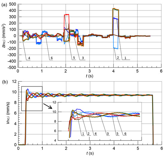
Figure 18.
Motion parameters of hydraulic actuators with the FLC3 controller for %; (a) acceleration, (b) speed; 1–6—line.
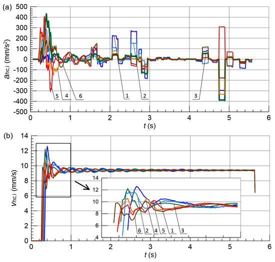
Figure 19.
Motion parameters of hydraulic actuators with the FLC3 controller for %; (a) acceleration, (b) speed; 1–6—line.
The results indicate that the speeds and accelerations are within the allowable range in both cases. The maximum instantaneous velocity does not exceed mm/s at % and mm/s for % (the permissible value is mm/s). The absolute values of acceleration in both cases do not exceed mm/s2, for the permissible value m/s2 mm/s2.
The acceleration profiles in Figure 18a and Figure 19a exhibit characteristic features requiring explanation. The apparent mismatch around s, where velocity slope is steepest but acceleration is not maximal, results from discrete control sampling ( s) combined with valve response delays—velocity, being an integrated quantity, reflects the dominant acceleration trend while instantaneous peaks occur due to transient corrections. Distinct acceleration spikes at s and s correspond to deliberate FLC commands: at s the controller initiates coordinated deceleration as actuators reach 80% of target position, while at s fine positioning corrections eliminate residual synchronization errors. These brief acceleration pulses ( s duration, mm/s) do not produce visible velocity discontinuities due to integration smoothing and partial cancellation among actuators. The control signals in Figure 12a and Figure 16a show corresponding step changes, confirming that acceleration variations result from the discrete-time Mamdani controller’s piecewise-constant output rather than mechanical instabilities.
6. Conclusions
This paper proposes an innovative solution to the problem of positioning a large-sized platform with a heavy load during vertical movement to a required height. A mathematical model of the hydraulic system was first formulated to achieve the set goal. Next, a simulation model was created, and a fuzzy logic control system (FLC) was designed. A series of simulations were performed for different load values of particular hydraulic cylinders and various fuzzy controller parameters, including two types of membership functions and two sets of fuzzy operators. The simulation results confirmed the system’s ability to achieve the assumed positioning accuracy. Based on the obtained results, the following detailed conclusions can be formulated:
- the effectiveness of fuzzy logic in the construction of a complex hydraulic drive control system with multiple inputs and outputs has been demonstrated,
- each tested fuzzy logic controller allowed the required positioning precision to be achieved; furthermore, the most efficacious solution was also verified to meet the permissible speed and acceleration requirements,
- Gaussian membership functions with operators (FLC3) demonstrated superior performance evaluated through synchronization error (), control effort (), and velocity uniformity—achieving 30–40% lower and maintaining mm even under 20% load imbalance, confirming practical applicability for precision positioning,
- the most significant differences in the actuator positions occur in their initial phase of movement, mainly caused by non-uniform loads, which may require further research.
This study is limited to numerical simulation without experimental validation. While the simulation model incorporates validated component characteristics from prior research [20,21] and follows established hydraulic modeling practices, several real-world phenomena may affect practical implementation. These include: (1) dynamic load redistribution as platform tilt shifts the center of gravity, creating actuator coupling not present in the constant-load model; (2) sensor noise and quantization effects in displacement measurement; (3) valve hysteresis and temperature-dependent viscosity changes during operation; and (4) structural compliance and mechanical backlash in joints and connections. The absence of these factors in simulation represents an idealized scenario that may overestimate synchronization performance.
To address this limitation, future work will pursue experimental validation through a two-phase approach. First, a reduced-scale test bench (∼10% of full size, tonnes) will be constructed to validate FLC behavior under controlled laboratory conditions, allowing systematic investigation of individual non-ideal effects. This scaled prototype will use geometrically similar actuators (piston diameter mm) operating at proportionally reduced pressures ( MPa) to maintain dynamic similarity while enabling cost-effective experimentation. Displacement sensors with mm resolution and 100 Hz sampling will provide high-quality validation data. Second, partial verification experiments on the full-scale PANDA detector platform are planned during commissioning, where lift cycles under various load distributions will test synchronization performance and allow FLC parameter refinement based on actual system response.
The nearest further research also concerns building a fuzzy-neuro control system where the defuzzification block is replaced with an artificial neural network (ANN). The effectiveness of networks differing in the number of neuron layers and activation functions will be examined, though this requires extensive training data from either simulation sweeps or experimental measurements. Hybrid fuzzy-neural approaches may offer improved adaptation to time-varying system parameters such as fluid temperature and component wear, extending the controller’s operational lifespan without manual retuning.
Author Contributions
Conceptualization, E.L.; methodology, G.F.; software, P.L.; validation, P.L. and K.W.; formal analysis, G.F.; investigation, K.W.; resources, K.W.; writing original draft preparation, G.F.; writing review and editing, E.L. and G.F.; visualization, K.W.; supervision, E.L.; project administration, P.L. All authors have read and agreed to the published version of the manuscript.
Funding
This research received no external funding.
Institutional Review Board Statement
Not applicable.
Informed Consent Statement
Not applicable.
Data Availability Statement
The results available on request.
Acknowledgments
The research was carried out as part of the statutory activities of the Faculty of Mechanical Engineering at the Cracow University of Technology.
Conflicts of Interest
The authors declare no conflict of interest.
References
- Zadeh, L. Fuzzy sets. Inf. Control 1965, 8, 338–353. [Google Scholar] [CrossRef]
- Filo, G. A Review of Fuzzy Logic Method Development in Hydraulic and Pneumatic Systems. Energies 2023, 16, 7584. [Google Scholar] [CrossRef]
- Bao, H.; He, D.; Zhang, B.; Zhong, Q.; Hong, H.; Yang, H. Research on Dynamic Performance of Independent Metering Valves Controlling Concrete-Placing Booms Based on Fuzzy-LADRC Controller. Actuators 2023, 12, 139. [Google Scholar] [CrossRef]
- Tatoglu, A.; Campana, C.; Nolan, J.; Toloczko, G. Fuzzy logic controller design of a single stage fluid valve based robotic arm. In Proceedings of the ASME International Mechanical Engineering Congress and Exposition, Proceedings (IMECE), Online, 16–19 November 2020; Volume 7B-2020. [Google Scholar] [CrossRef]
- Tony Thomas, A.; Thangarasu, S.; Sowmithra, T. Modeling and Simulation of an Electro-Hydraulic System Using Fuzzy Logic Approach. In Fluid Mechanics and Fluid Power; Lecture Notes in Mechanical Engineering; Springer: Singapore, 2021; pp. 807–822. [Google Scholar] [CrossRef]
- Wrat, G.; Bhola, M.; Ranjan, P.; Mishra, S.K.; Das, J. Energy saving and Fuzzy-PID position control of electro-hydraulic system by leakage compensation through proportional flow control valve. ISA Trans. 2020, 101, 269–280. [Google Scholar] [CrossRef] [PubMed]
- Ur Rehman, W.; Wang, X.; Hameed, Z.; Gul, M.Y. Motion Synchronization Control for a Large Civil Aircraft’s Hybrid Actuation System Using Fuzzy Logic-Based Control Techniques. Mathematics 2023, 11, 1576. [Google Scholar] [CrossRef]
- Do, T.C.; Tran, D.T.; Dinh, T.Q.; Ahn, K.K. Tracking Control for an Electro-Hydraulic Rotary Actuator Using Fractional Order Fuzzy PID Controller. Electronics 2020, 9, 926. [Google Scholar] [CrossRef]
- Li, M.; Zhang, Q. Adaptive Robust Fuzzy Impedance Control of an Electro-Hydraulic Actuator. Appl. Sci. 2022, 12, 9575. [Google Scholar] [CrossRef]
- Lu, Y.; Cao, P.; Xiong, L.; Xu, B. A Novel Fuzzy Logic Control on the FVVT Lift of Internal Combustion Engine. In Proceedings of the 10th International Conference On Intelligent Control And Information Processing (ICICIP), Marrakesh, Morocco, 14–19 December 2019; pp. 126–132. [Google Scholar]
- Guo, H.; Hu, M.; Li, T.; Li, G. Design and Simulation of Variable Pitch Control System Based on Fuzzy Model Reference Adaptive. In Practical Applications of Intelligent Systems; Advances in Intelligent Systems and Computing; Wen, Z., Li, T., Eds.; Springer: Berlin/Heidelberg, Germany, 2014; Volume 279, pp. 745–754. [Google Scholar]
- Nguyen, M.N.; Tran, D.T.; Ahn, K.K. Robust position and vibration control of an electrohydraulic series elastic manipulator against disturbance generated by a variable stiffness actuator. Mechatronics 2018, 52, 22–35. [Google Scholar] [CrossRef]
- Tho, N.H.; Phuong, V.N.Y.; Danh, L.T. Development of an Adaptive Fuzzy Sliding Mode Controller of an Electrohydraulic Actuator Based on a Virtual Prototyping. Actuators 2023, 12, 258. [Google Scholar] [CrossRef]
- Truong, H.V.A.; Tran, D.T.; To, X.D.; Ahn, K.K.; Jin, M. Adaptive Fuzzy Backstepping Sliding Mode Control for a 3-DOF Hydraulic Manipulator with Nonlinear Disturbance Observer for Large Payload Variation. Appl. Sci. 2019, 9, 3290. [Google Scholar] [CrossRef]
- Jin, X.; Chen, K.; Zhao, Y.; Ji, J.; Jing, P. Simulation of hydraulic transplanting robot control system based on fuzzy PID controller. Measurement 2020, 164, 108023. [Google Scholar] [CrossRef]
- Rodríguez-Pérez, A.M.; Rodríguez, C.A.; Márquez-Rodríguez, A.; Mancera, J.J.C. Viability Analysis of Tidal Turbine Installation Using Fuzzy Logic: Case Study and Design Considerations. Axioms 2023, 12, 778. [Google Scholar] [CrossRef]
- Davì, F.; Erni, W.; Krusche, B.; Steinacher, M.; Walford, N.; Liu, H.; Liu, Z.; Liu, B.; Shen, X.; Wang, C.; et al. PANDA Phase One. Eur. Phys. J. A 2021, 57, 184. [Google Scholar] [CrossRef]
- Davì, F.; Erni, W.; Krusche, B.; Steinacher, M.; Walford, N.; Liu, H.; Liu, Z.; Liu, B.; Shen, X.; Wang, C.; et al. Technical design report for the P¯ANDA endcap disc DIRC. J. Phys. G Nucl. Part. Phys. 2022, 49, 120501. [Google Scholar] [CrossRef]
- Stryczek, S. Napęd Hydrostatyczny. Tom 1 Elementy; WNT: Warsaw, Poland, 2016. [Google Scholar]
- Lisowski, E.; Filo, G.; Rajda, J. Pressure compensation using flow forces in a multi-section proportional directional control valve. Energy Convers. Manag. 2015, 103, 1052–1064. [Google Scholar] [CrossRef]
- Lisowski, E.; Filo, G. CFD analysis of the characteristics of a proportional flow control valve with an innovative opening shape. Energy Convers. Manag. 2016, 123, 15–28. [Google Scholar] [CrossRef]
Disclaimer/Publisher’s Note: The statements, opinions and data contained in all publications are solely those of the individual author(s) and contributor(s) and not of MDPI and/or the editor(s). MDPI and/or the editor(s) disclaim responsibility for any injury to people or property resulting from any ideas, methods, instructions or products referred to in the content. |
© 2025 by the authors. Licensee MDPI, Basel, Switzerland. This article is an open access article distributed under the terms and conditions of the Creative Commons Attribution (CC BY) license (https://creativecommons.org/licenses/by/4.0/).