


The Reactivated Residual Strength: Laboratory Tests and Practical Considerations

Abstract
1. Introduction
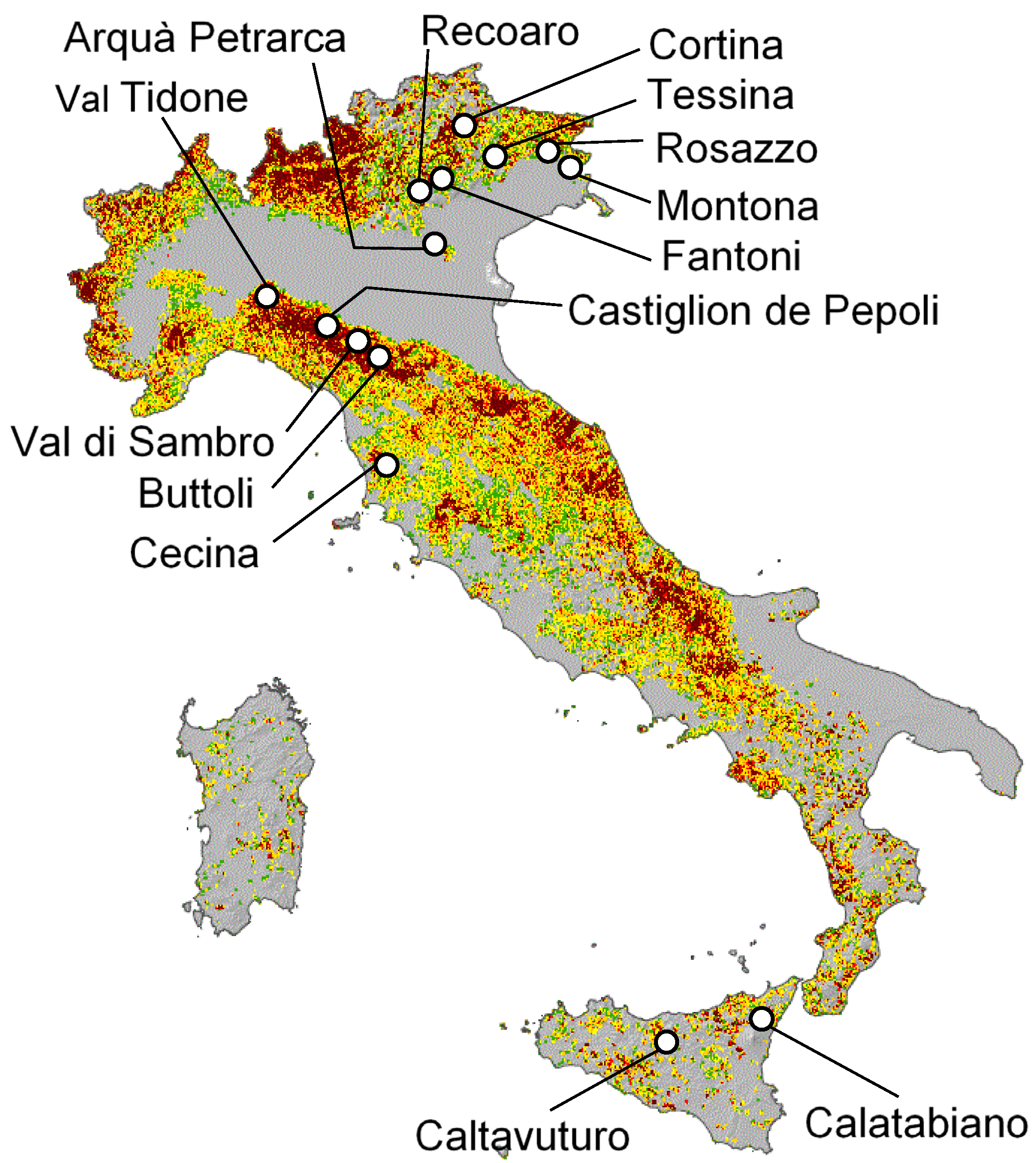
2. The Database
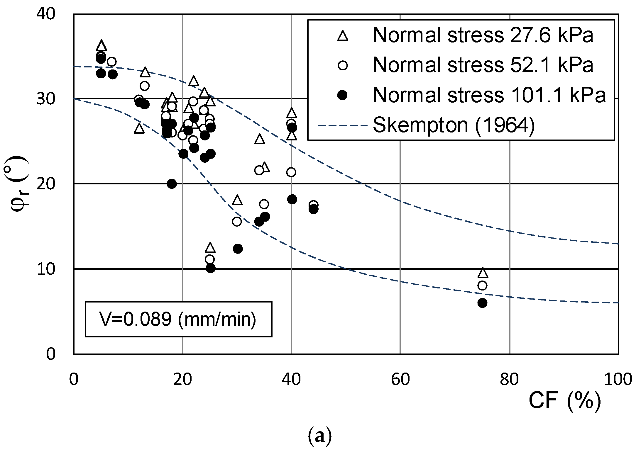
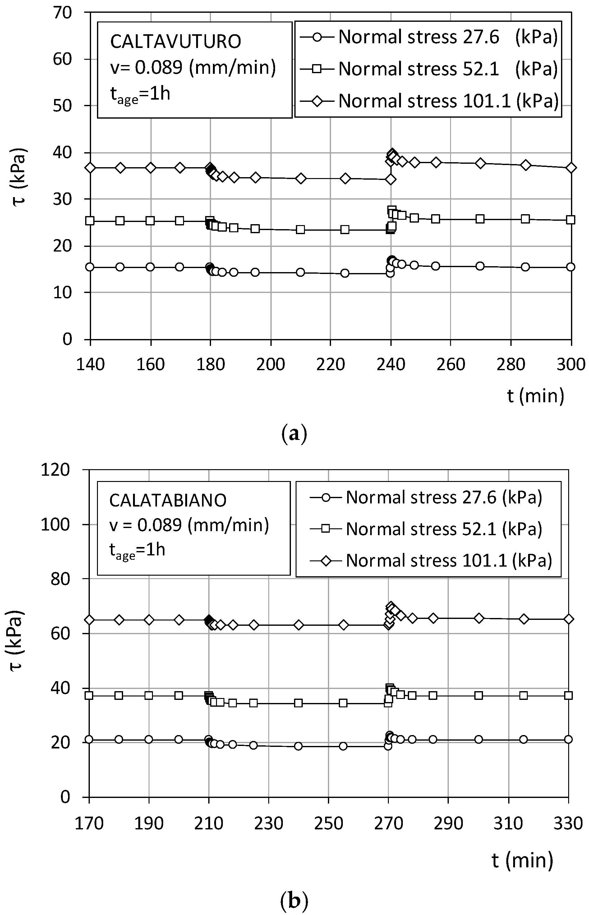
3. Steady-State and Reactivated Residual Strength
4. Some Possible Reasons to Explain the Strength Recovery upon Reactivation
4.1. Transition from Static to Kinetic Strength: The Role of Viscosity
4.2. Ageing and Creep
4.3. Thixotropy
5. Conclusions
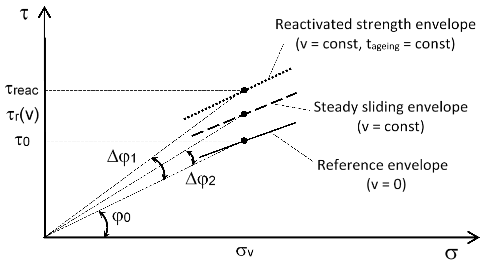
- The stress condition, τ0, reached after relaxation under zero displacement speed should identify a reference condition for which shear creep can attenuate within the primary phase;
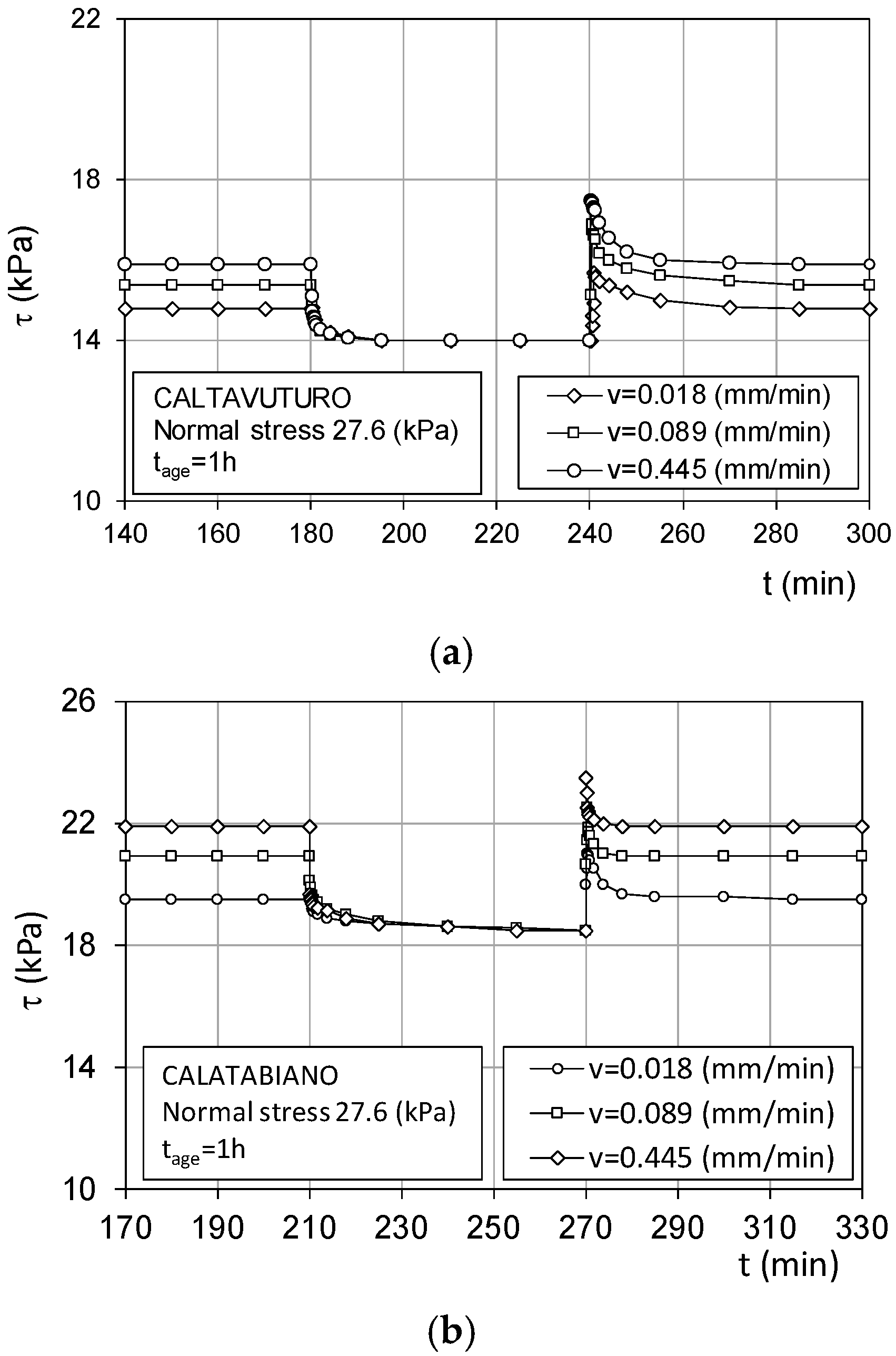
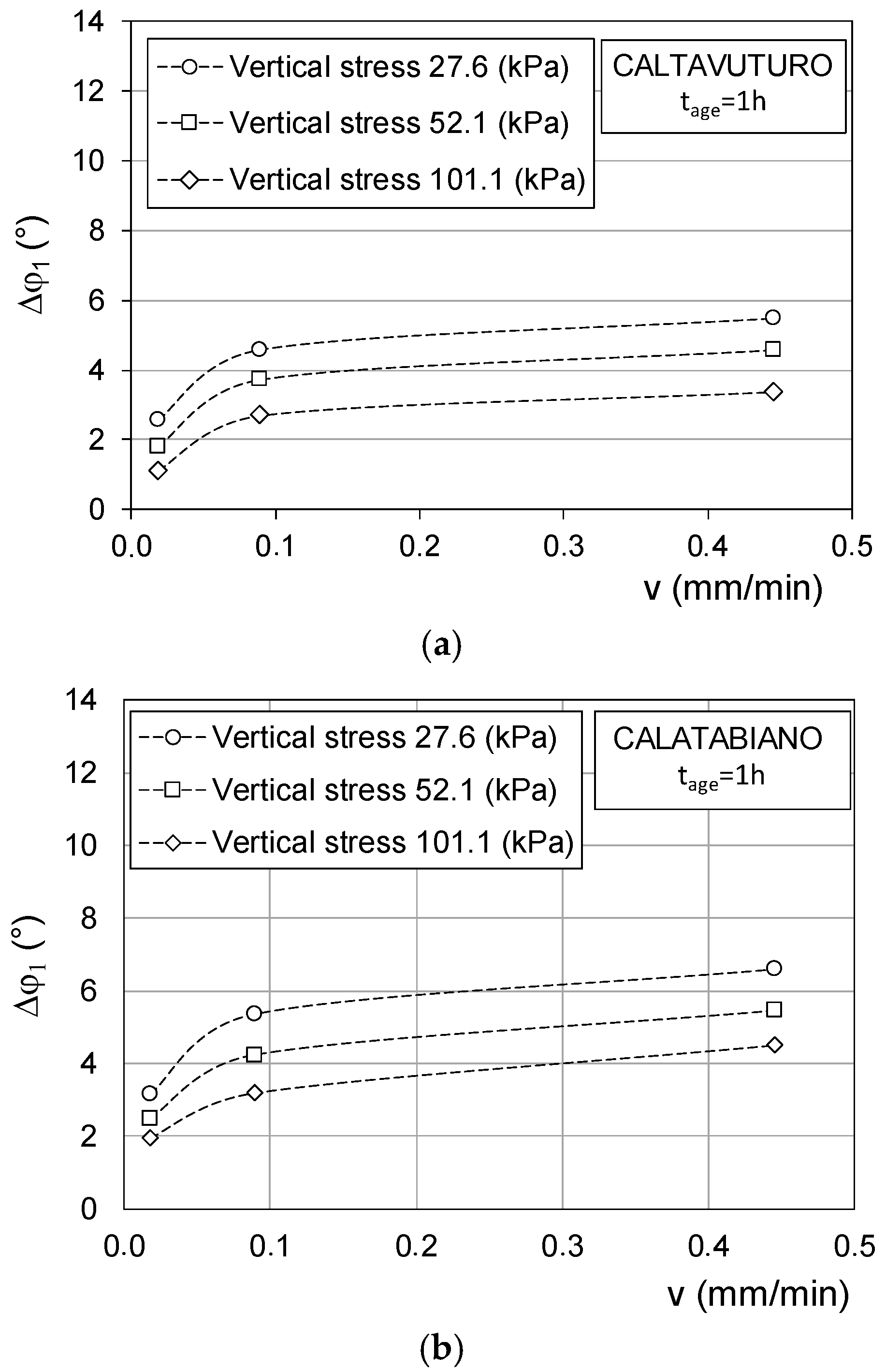
- After quiescence at τ0 stress, the strength at reactivation could exceed the residual value, τr(v), depending on the ageing time, the shearing speed, and the vertical stress. This could be the consequence of some causes, such as viscosity, volumetric creep, and thixotropic hardening, which can account for an initial reactivated strength proportional to the ageing time and the reactivation speed;
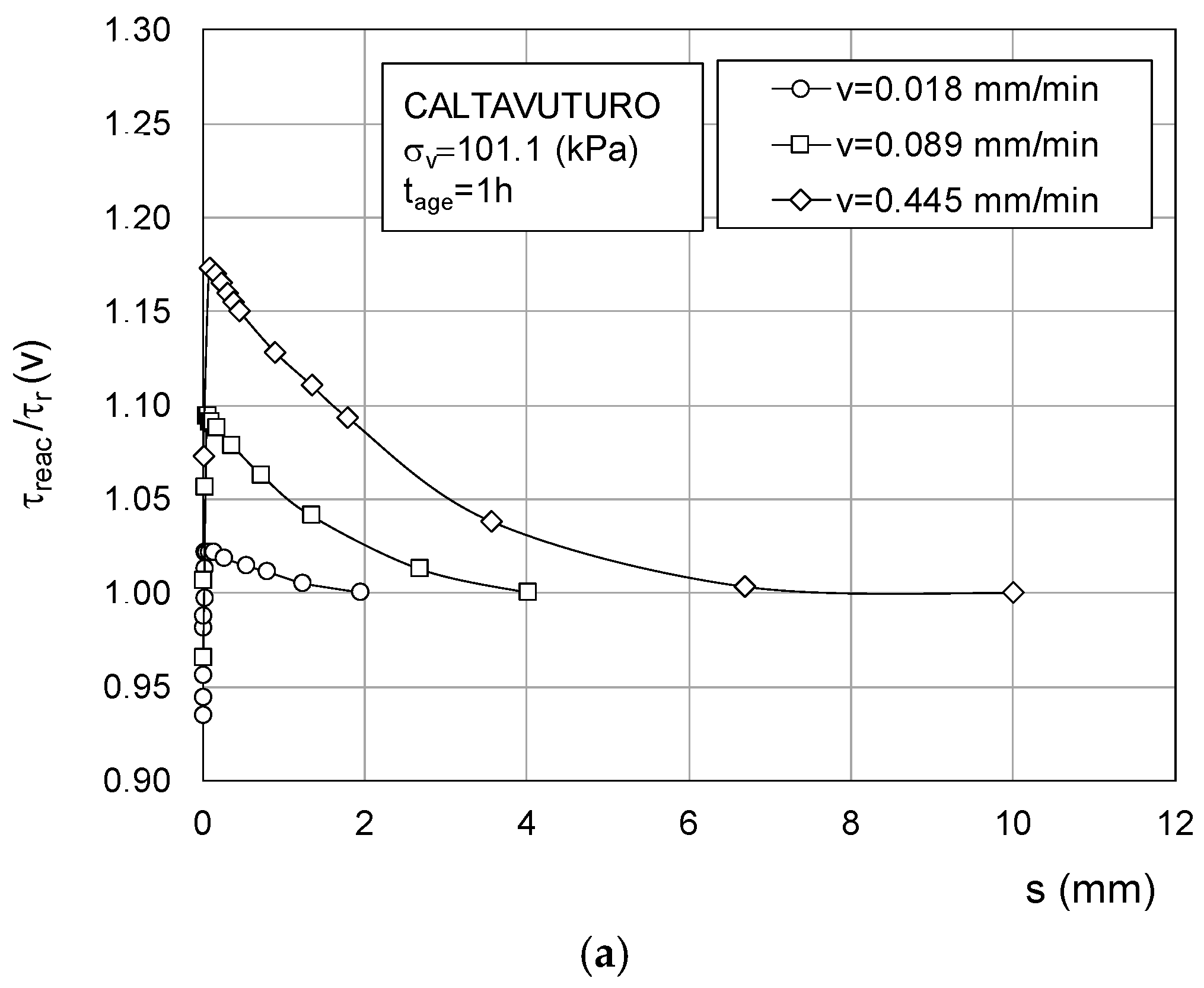
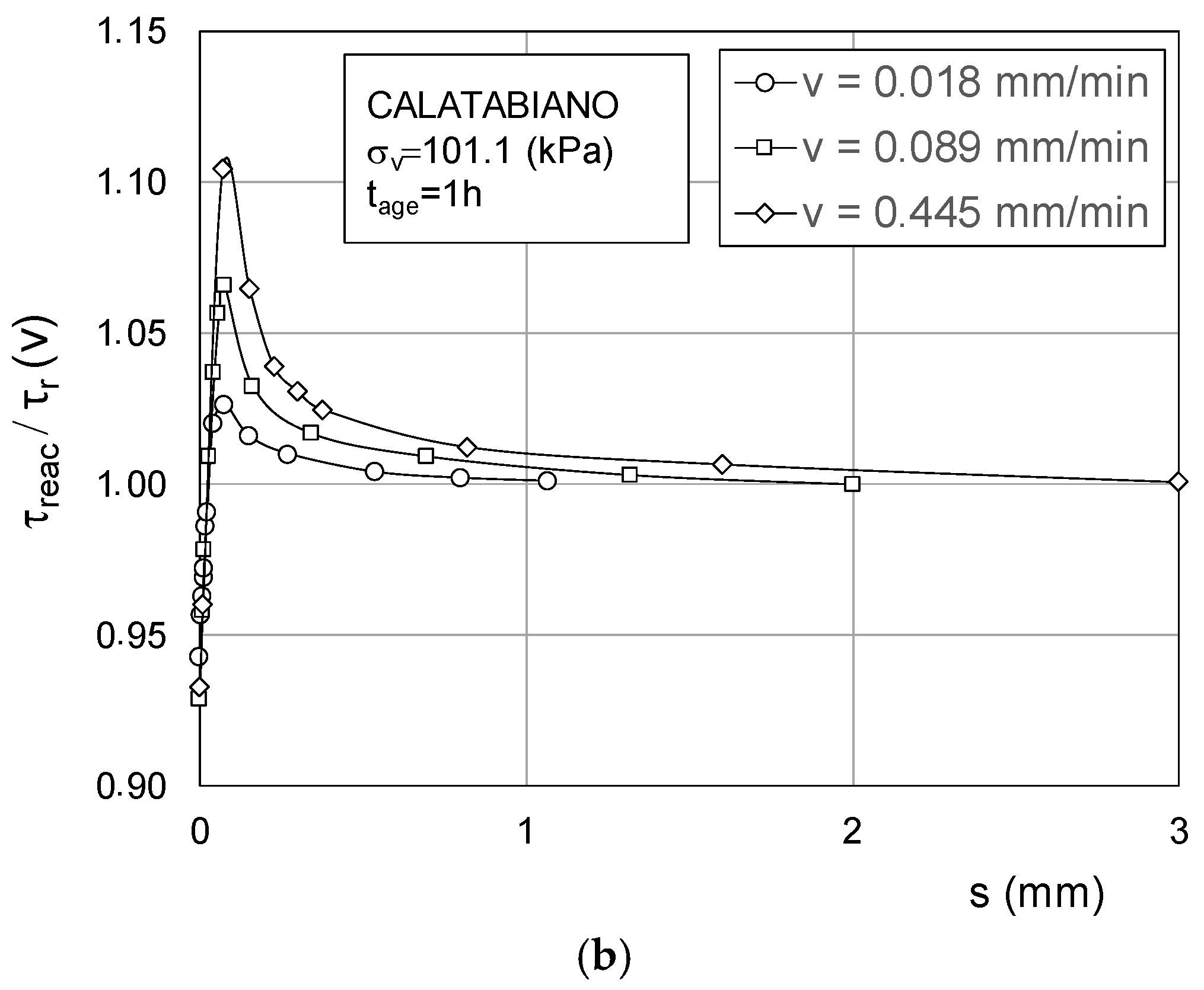
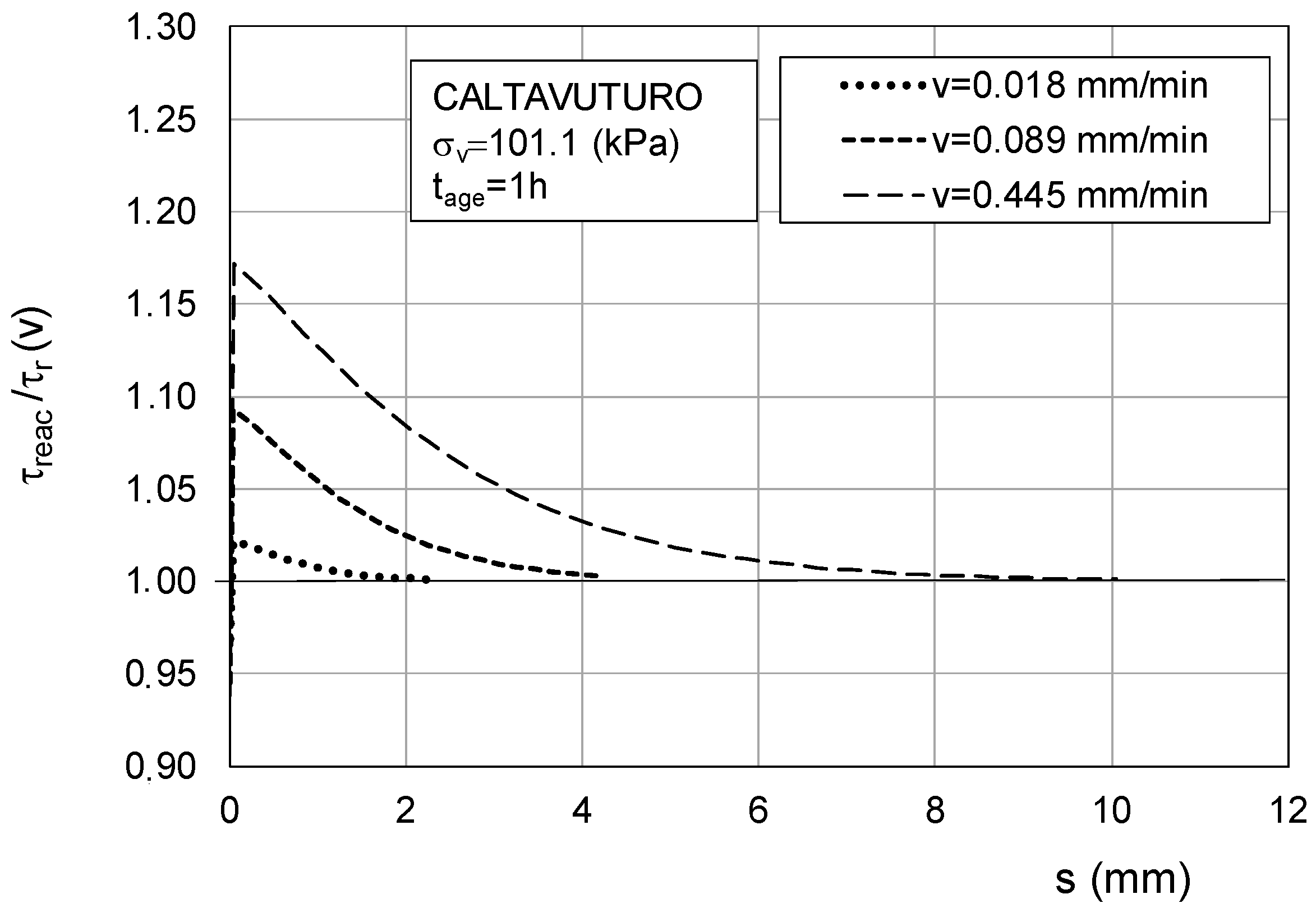
- The reactivated strength rapidly falls towards τr(v) as the displacement increased at constant speed. This would mean that the aged soil fabric undergoes destructuration;
- If reactivation occurred at a displacement speed approaching zero, the reactivated shear strength approached the reference value,τ0, irrespective of the amount of time spent in the previous ageing phase; this could occur if the strength at reactivation depended only on the viscous reaction of the particle edge-to-face hinges.
Funding
Institutional Review Board Statement
Informed Consent Statement
Data Availability Statement
Conflicts of Interest
Nomenclature
| σv | vertical stress |
| v | displacement speed |
| s | cumulated displacement |
| creac | viscous constant of soil at reactivation |
| c | viscous constant of soil under residual steady condition |
| β, δ | constants of Equation (4) |
| τ0 | reference strength at zero displacement speed |
| tage | time of quiescence under τ0 condition |
| τreact | maximum strength at reactivation for given σv and v |
| τr(v) | steady strength at constant displacement speed |
| ∆τ1 = τreact − τ0 | maximum shear strength increase during reactivation |
| ∆τ2 = τr(v) − τ0 | shear strength increase under steady condition |
| φ0 | secant strength angle associated with τ0 and σv stress state |
| φr | secant strength angle associated with τr(v) and σv stress state |
| φreac | secant strength angle associated with τreact and σv stress state |
| ∆φ1 | increase in secant strength angle corresponding to ∆τ1 |
| ∆φ2 | increase in secant strength angle corresponding to ∆τ2 |
| comparison parameter | |
| PI | plastic index |
| OCR | overconsolidation ratio |
| FF | fine fraction |
| CF | clay fraction |
| AI | activity index |
| wP | plastic limit |
| wL | liquid limit |
References
- Alonso, E.E.; Pinyol, N.M. Slope stability in slightly fissured clay stones and marls. Landslides 2015, 12, 643–656. [Google Scholar] [CrossRef]
- Skempton, A.W. Long term stability of clay slopes. Geotechnique 1964, 14, 77–102. [Google Scholar] [CrossRef]
- Skempton, A.W. Residual strength of clays in landslides, folded strata and the laboratory. Geotechnique 1985, 35, 3–18. [Google Scholar] [CrossRef]
- Mesri, G.; Huvaj-Sarihan, N. Residual shear strength measured by laboratory tests and mobilised in landslides. J. Geotech. Geoenviron. Eng. 2012, 138, 585–593. [Google Scholar] [CrossRef]
- Gibo, S.; Egashira, K.; Ohtsubo, M.; Nakamura, S. Strength recovery from residual state in reactivated landslides. Geotechnique 2002, 52, 683–686. [Google Scholar] [CrossRef]
- Angeli, M.G.; Gasparetto, P.; Bromhead, N. Strength-regain mechanisms in intermittently moving slides. In Proceedings of the 9th International Symposium on Landslides, Rio de Janeiro, Brazil, 28 June–2 July 2004; Taylor & Francis: London, UK, 2004; Volume 1, pp. 689–696. [Google Scholar]
- Stark, T.D.; Choi, H.; McCone, S. Drained shear strength parameters for analysis of landslides. J. Geotech. Geoenviron. Eng. 2005, 131, 575–588. [Google Scholar] [CrossRef]
- Carrubba, P.; Del Fabbro, M. Laboratory investigation on reactivated residual strength. J. Geotech. Geoenviron. Eng. 2008, 134, 302–315. [Google Scholar] [CrossRef]
- Stark, T.D.; Hussain, M. Shear strength in preexisting landslides. J. Geotech. Geoenviron. Eng. 2010, 136, 957–962. [Google Scholar] [CrossRef]
- Stark, T.D.; Hussain, M. Drained residual strength for landslides. In Proceedings of the GeoFlorida 2010, Advances in Analysis, Modeling & Design, West Palm Beach, FL, USA, 20–24 February 2010; pp. 3217–3226. [Google Scholar]
- Bhat, D.R.; Yatabe, R.; Bhandary, N.P. Study of preexisting shear surfaces of reactivated landslides from a strength recovery perspective. J. Asian Earth Sci. 2013, 77, 243–253. [Google Scholar] [CrossRef]
- Bhat, D.R.; Bhandary, N.P.; Yatabe, R.; Dahal, R.K.; Tiwari, R.C. Strength recovery from residual-state of shear on soils. Indian Geotech. J. 2014, 44, 94–100. [Google Scholar] [CrossRef]
- D’Appolonia, E.; Alperstein, R.; D’Appolonia, D.J. Behaviour of a colluvial slope. J. Soil Mech. Found. Div. 1967, 93, 447–473. [Google Scholar] [CrossRef]
- Hamel, J.V.; Adams, W.R. Discussion of “Shear strength in preexisting landslides” by Timothy D. Stark and Manzoor Hussain. J. Geotech. Geoenviron. Eng. 2011, 137, 809–811. [Google Scholar] [CrossRef]
- Zhang, Y.; Guo, C.; Lan, H.; Zhou, N.; Yao, X. Reactivation mechanism of ancient giant landslides in the tectonically active zone: A case study in Southwest China. Environ. Earth Sci. 2015, 74, 1719–1729. [Google Scholar] [CrossRef]
- Yan, Q.; Li, X.; He, S.; Luo, Y.; Tian, H.; Wu, Y. Experimental study of self-healing of slip zone soil in typical red bed landslide. Rock Soil Mech. 2020, 41, 3041–3048. [Google Scholar]
- Jiang, S.; Wang, Y.; Tang, C.; Wan, L.; Wang, K.; Wu, L.; Zhang, X.; Station, P. Movement mechanism of a reactivated slow-moving landslide based on ring shear test. Geol. Sci. Technol. Inf. 2019, 38, 256–261. [Google Scholar]
- Wang, H.; Gao, D.; Wu, B. Experimental study on strength regeneration of slip zone soils considering residual shear stress. Chin. J. Geol. Hazard Control 2020, 31, 5. [Google Scholar]
- Dong, W.; Wan, F.; Xu, Q.; Dong, J. Healing of undisturbed slide zone soil: Experimental study on the Huaipa landslide in Sanmenxia city. Appl. Sci. 2024, 14, 4484. [Google Scholar] [CrossRef]
- Miao, H.; Wang, G.; Yin, K.; Kamai, T.; Li, Y. Mechanism of the slow-moving landslides in Jurassic red-strata in the Three Gorges Reservoir, China. Eng. Geol. 2014, 171, 59–69. [Google Scholar] [CrossRef]
- Miao, H.; Wang, G. Effects of clay content on the shear behaviours of sliding zone soil originating from muddy interlayers in the Three Gorges Reservoir, China. Eng. Geol. 2021, 294, 106380. [Google Scholar] [CrossRef]
- Zheng, Y.; Coop, M.R.; Tang, H.; Fan, Z. Effects of overconsolidation on the reactivated residual strength of remoulded deep-seated sliding zone soil in the Three Gorges Reservoir Region, China. Eng. Geol. 2022, 310, 106882. [Google Scholar] [CrossRef]
- Qi, T.; Meng, X.; Chang, J.; Yue, D.; Wang, Y.; Chen, G. Landslide utilization and driving mechanisms in alpine gorge areas of the eastern Qinghai–Tibet Plateau. Catena 2025, 249, 108677. [Google Scholar] [CrossRef]
- Alvarado, M.; Pinyol, N.M.; Alonso, E.E. Landslide motion assessment including rate effects and thermal interactions: Revisiting the Canelles landslide. Can. Geotech. J. 2019, 56, 1338–1350. [Google Scholar] [CrossRef]
- Di Maio, C.; Fenelli, G.B. Residual strength of kaolin and bentonite: The influence of their constituent pore fluid. Géotechnique 1994, 44, 217–226. [Google Scholar] [CrossRef]
- Gao, Y.; Hao, D.; Liu, X.; Chen, K.; Chen, R.; Guo, R. Experimental investigation on characteristics of strength recovery and pore structure of Jilin ball clay under freeze–thaw cycles. Sci. Rep. 2024, 14, 16659. [Google Scholar] [CrossRef] [PubMed]
- ISPRA. Dissesto Idrogeologico in Italia: Pericolosità e Indicatori di Rischio. Ed. 356/2021. 2021; ISBN 978-88-448-1085-6. Available online: https://www.isprambiente.gov.it/it/pubblicazioni/rapporti/dissesto-idrogeologico-in-italia-pericolosita-e-indicatori-di-rischio-edizione-2021 (accessed on 6 March 2024).
- Lupini, J.F. The Residual Strength of Soils. Ph.D. Thesis, University of London, London, UK, 1981. [Google Scholar]
- Parathiras, A.N. Displacement rate and shear direction effects on the residual strength of plastic soils. In Proceedings of the 7th International Conference on Soil Dynamics and Earthquake Engineering, Chania, Crete, Greece, 14–26 May 1995; pp. 67–72. [Google Scholar]
- Tika, T.E.; Vaughan, P.R.; Lemos, L.J. Fast shearing of pre-existing shear zones in soil. Geotechnique 1996, 46, 197–233. [Google Scholar] [CrossRef]
- Grelle, G.; Guadagno, F.M. Shear mechanisms and viscoplastic effects during impulsive shearing. Geotechnique 2010, 60, 91–103. [Google Scholar] [CrossRef]
- Gratchev, I.B.; Sassa, K. Shear strength of clay at different shear rates. J. Geotech. Geoenviron. Eng. 2015, 141, 06015002. [Google Scholar] [CrossRef]
- Cruden, D.M.; Varnes, D.J. Landslide Types and Processes; Special Report; Transportation Research Board, U.S. National Academy of Sciences: Washington, DC, USA, 1996; Volume 247, pp. 36–75. [Google Scholar]
- Hungr, O.; Leroueil, S.; Picarelli, L. The Varnes classification of landslide types, an update. Landslides 2014, 11, 167–194. [Google Scholar] [CrossRef]
- Pinyol, N.M.; Alvarado, M.; Garcia, L.M. Dynamics of slow and fast landslides. In Proceedings of the XIII International Symposium on Landslides, Cartagena, Colombia, 22–26 February 2021; pp. 1–30. [Google Scholar]
- Bhat, D.R.; Bhandary, N.P.; Yatabe, R.; Tiwari, R.C. Residual-state creep test in modified torsional ring shear machine: Methods and implications. Int. J. Geomate 2011, 1, 39–43. [Google Scholar]
- Di Maio, C.; Vassallo, R.; Vallario, M. Plastic and viscous shear displacements of a deep and very slow landslide in stiff clay formation. Eng. Geol. 2013, 162, 53–66. [Google Scholar] [CrossRef]
- Wang, S.; Wu, W.; Wang, J.; Yin, Z.; Cui, D.; Xiang, W. Residual-state creep of clastic soil in a reactivated slow-moving landslide in the Three Gorges Reservoir Region, China. Landslides 2018, 15, 2413–2422. [Google Scholar] [CrossRef]
- Wen, B.P.; Jiang, X.Z. Effect of gravel content on creep behaviour of clayey soil at residual state: Implication for its role in slow-moving landslides. Landslides 2017, 14, 559–576. [Google Scholar] [CrossRef]
- Schmertmann, J.H. The mechanical ageing of soils. J. Geotech. Eng. 1991, 117, 1288–1330. [Google Scholar] [CrossRef]
- Mitchell, J.K.; Soga, K. Fundamentals of Soil Behaviour; John Wiley & Sons, Inc.: Hoboken, NJ, USA, 2005. [Google Scholar]
- Bjerrum, L. Engineering geology of Norwegian normally-consolidated marine clays as related to the settlements of buildings. Geotechnique 1967, 17, 83–118. [Google Scholar] [CrossRef]
- Vyalov, S.S. Rheological Fundamentals of Soil Mechanics; Elsevier: Amsterdam, The Netherlands, 1986; Volume 36, 564p. [Google Scholar]
- Meschyan, S.R. Experimental Rheology of Clayey Soils; Geotechnika 13; A.A. Balkema Publishers: Rotterdam, The Netherlands, 1995; 448p. [Google Scholar]
- Helmstetter, A.; Sornette, D.; Grasso, J.R.; Andersen, J.V.; Gluzman, S.; Pisarenko, V. Slider-block friction model for landslides: Application to Vajont and La Clapière landslides. J. Geophys. Res. 2004, 109, B02409. [Google Scholar] [CrossRef]
- Alonso, E.E.; Zervos, A.; Pinyol, N.M. Thermo-poro-mechanical analysis of landslides: From creeping behaviour to catastrophic failure. Géotechnique 2016, 66, 202–219. [Google Scholar] [CrossRef]
- Mitchell, J.K. Fundamental aspect of thixotropic in soils. J. Soil Mech. Found. Div. 1960, 85, 19–52. [Google Scholar] [CrossRef]
- Ramiah, B.K.; Purushothamaraj, P.; Tavane, N.G. Thixotropic effects on residual strength of remoulded clays. Indian Geotech. J. 1973, 3, 189–197. [Google Scholar]
- Barnes, H.A. Thixotropy—A review. J. Non-Newton. Fluid Mech. 1997, 70, 1–33. [Google Scholar] [CrossRef]


| Sample Identification | Fine Fraction FF (%) | Clay Fraction CF (%) | Liquid Limit wL (%) | Plastic Limit wP (%) | Plasticity Index PI (%) | Activity Index AI | (V = 0.089 mm/min) | Comparison Parameter |
|---|---|---|---|---|---|---|---|---|
| Sodium Bentonite | 98 | 75 | 346 | 68 | 278 | 3.71 | 7.7 | 5.19 |
| Kaolin | 100 | 22 | 46 | 24 | 22 | 1.00 | 25.4 | 1.83 |
| Buttoli 1 | 77 | 25 | 38 | 18 | 20 | 0.80 | 11.0 | 2.50 |
| Buttoli 2 | 81 | 30 | 45 | 22 | 23 | 0.77 | 15.3 | 2.41 |
| Cecina | 75 | 35 | 53 | 27 | 26 | 0.74 | 18.5 | 2.26 |
| Val di Sambro 1 | 53 | 17 | 44 | 23 | 21 | 1.24 | 27.5 | 1.65 |
| Fantoni S8 | 80 | 20 | 76 | 36 | 40 | 2.00 | 25.1 | 1.67 |
| Fantoni S10 | 91 | 40 | 97 | 50 | 47 | 1.18 | 22.1 | 1.74 |
| Fantoni S12 | 58 | 12 | 60 | 27 | 33 | 2.75 | 28.7 | 1.67 |
| Fantoni A | 68 | 13 | 48 | 31 | 17 | 1.31 | 31.3 | 0.97 |
| Fantoni E | 92 | 17 | 56 | 24 | 32 | 1.88 | 27.9 | 2.04 |
| Fantoni I | 79 | 25 | 66 | 39 | 27 | 1.08 | 26.9 | 1.33 |
| Fantoni L | 85 | 24 | 74 | 37 | 37 | 1.54 | 26.0 | 1.65 |
| Fantoni M | 81 | 24 | 69 | 44 | 25 | 1.04 | 28.3 | 1.11 |
| Rosazzo | 70 | 25 | 45 | 22 | 23 | 0.92 | 27.0 | 2.18 |
| Rosazzo 1 | 85 | 22 | 47 | 27 | 20 | 0.91 | 29.8 | 1.56 |
| Montona | 75 | 40 | 51 | 24 | 27 | 0.68 | 27.3 | 2.79 |
| Castiglion de Pepoli | 58 | 18 | 46 | 26 | 20 | 1.11 | 29.0 | 1.46 |
| Val Tidone C | 97 | 34 | 52 | 28 | 24 | 0.71 | 20.8 | 2.07 |
| Tessina S | 93 | 21 | 41 | 26 | 15 | 0.71 | 27.4 | 1.38 |
| Tessina C | 75 | 17 | 37 | 23 | 14 | 0.82 | 27.3 | 1.35 |
| Arquà Petrarca | 53 | 5 | 34 | 29 | 5 | 1.00 | 35.3 | 0.34 |
| Recoaro | 47 | 7 | 25 | 20 | 5 | 1.00 | 33.5 | 0.60 |
| Caltavuturo | 63 | 18 | 48 | 25 | 23 | 1.28 | 24.1 | 1.64 |
| Calatabiano | 53 | 5 | 33 | 26 | 7 | 1.40 | 33.2 | 0.46 |
| Cortina | 96 | 44 | 69 | 35 | 34 | 0.77 | 17.2 | 2.23 |
| v (mm/min) | τreac (kPa) | τr(v) (kPa) | τ0 (kPa) | τreac/τr(v) | creac (kPa)/(mm/min) | c (kPa)/(mm/min) | β | δ |
|---|---|---|---|---|---|---|---|---|
| 0.018 | 36.50 | 35.70 | 34.30 | 1.022 | 122.22 | 77.78 | 1.10 | 1.30 |
| 0.089 | 39.70 | 36.30 | 34.30 | 1.094 | 60.67 | 22.47 | 0.55 | 1.28 |
| 0.445 | 43.40 | 37.00 | 34.30 | 1.173 | 20.45 | 6.07 | 0.31 | 1.22 |
Disclaimer/Publisher’s Note: The statements, opinions and data contained in all publications are solely those of the individual author(s) and contributor(s) and not of MDPI and/or the editor(s). MDPI and/or the editor(s) disclaim responsibility for any injury to people or property resulting from any ideas, methods, instructions or products referred to in the content. |
© 2025 by the author. Licensee MDPI, Basel, Switzerland. This article is an open access article distributed under the terms and conditions of the Creative Commons Attribution (CC BY) license (https://creativecommons.org/licenses/by/4.0/).
Share and Cite
Carrubba, P. The Reactivated Residual Strength: Laboratory Tests and Practical Considerations. Appl. Sci. 2025, 15, 7976. https://doi.org/10.3390/app15147976
Carrubba P. The Reactivated Residual Strength: Laboratory Tests and Practical Considerations. Applied Sciences. 2025; 15(14):7976. https://doi.org/10.3390/app15147976
Chicago/Turabian StyleCarrubba, Paolo. 2025. "The Reactivated Residual Strength: Laboratory Tests and Practical Considerations" Applied Sciences 15, no. 14: 7976. https://doi.org/10.3390/app15147976
APA StyleCarrubba, P. (2025). The Reactivated Residual Strength: Laboratory Tests and Practical Considerations. Applied Sciences, 15(14), 7976. https://doi.org/10.3390/app15147976