Article

Comparative Analysis of Studies of Geological Conditions at the Planning and Construction Stage of Dam Reservoirs: A Case Study of New Facilities in South-Western Poland

by
Maksymilian Połomski
1,2,
Mirosław Wiatkowski
1,* and
Gabriela Ługowska
1
1
Institute of Environmental Engineering, Wrocław University of Environmental and Life Sciences, Grunwaldzki 24, 50-363 Wrocław, Poland
2
State Water Holding Polish Waters–Regional Water Management Authority in Wrocław, Norwida 34, 50-950 Wrocław, Poland
*
Author to whom correspondence should be addressed.
Appl. Sci. 2025, 15(14), 7811; https://doi.org/10.3390/app15147811
Submission received: 16 May 2025 / Revised: 6 July 2025 / Accepted: 10 July 2025 / Published: 11 July 2025

Abstract

Geological surveys have vital importance at the planning stage of dammed reservoir construction projects. The results of these surveys determine the majority of the technical solutions adopted in the construction design to ensure the proper safety and stability parameters of the structure during water damming. Where the ground type is found to be different from what is expected, the construction project may be delayed or even cancelled. This study analyses issues and design modifications caused by the identification of different soil conditions during the construction of four new flood control reservoirs in the Nysa Kłodzka River basin in south-western Poland. The key findings are as follows: (1) a higher density of exploratory boreholes in areas with potentially fractured rock mass is essential for selecting the appropriate anti-filtration protection; (2) when deciding to apply deep piles, it is reasonable to verify, at the planning stage, whether they can be installed using the given technology directly at the planned site; (3) inaccurate identification of foundation soils under the dam body can lead to significant design modifications—in contrast, a denser borehole grid helps to determine the precise elevation of the base layer, which is essential for reliably estimating the volume of material required for the embankment; (4) in order to correctly assess the soil deposits located, for instance, in the reservoir basin area, it is more effective to use test excavations rather than relying solely on borehole-based investigations—as a last resort, test excavations can be used to supplement the latter.

1. Introduction

The comprehensive design of large hydrotechnical structures such as dammed reservoirs requires detailed surveys of the project site [1,2], including not only environmental and hydrological surveys but also geotechnical and engineering investigations, in order to determine the soil conditions at the future construction site. These investigations may be regulated by law, as exemplified by the Polish Regulation [3]. This regulation specifies the principles for establishing geotechnical foundation conditions for construction projects, classifies planned structures into appropriate geotechnical categories (based on factors such as structure size and soil complexity) and defines the standards [4,5,6,7,8,9,10] for conducting and interpreting laboratory tests.
In addition to defining the overall geological structure of the entire reservoir area, the data that the geotechnical documentation must crucially provide for these structures include the identification of the subsoil beneath the dam (and the depth of the load-bearing soils) and the classification of the soils in the reservoir basin in terms of their permeability and suitability for the construction of the dam body embankment (for an earthen dam) or side levees, if any, to adjust the existing terrain morphology [11]. It is therefore essential to characterise the key parameters of the soils available, such as the plasticity index and degree, the filtration coefficient, the natural and optimum moisture content, the organic matter content, the angle of internal friction and the cohesion [12]. Comparable approaches are applied in the petrographic and petrophysical characterisation of natural stones intended for structural use, where understanding their mechanical behaviour is equally essential for ensuring durability and stability in engineering applications [13]. By properly identifying these soil conditions, it is possible to select the most advantageous design variant, ensuring the safety of the structure, i.e., a sufficiently deep dam foundation, the use of appropriately scaled additional structural elements (such as anti-filtration screens) and the use of soils with the best properties to reduce the internal erosion of the embankment, one of the most common causes of dam failures [14]. Recent advances in the estimation of geotechnical parameters, such as cohesion or Young’s modulus, using regression analysis and soft computing techniques, significantly support the design of earth structures in complex geological settings [15,16]. Significantly, having accurate data on the extent and type of deposits in the reservoir basin plays a major role in analysing the economic feasibility of a project. Being able to use available materials, with no need for purchase and transportation, substantially reduces the overall project cost [17]. Here, however, there is a risk that, if insufficient survey data are collected, the volume of soil deposits may be overestimated or that more contamination of the planned construction soil with other fractions may be discovered during excavation. Furthermore, if it is determined during the construction process that the dam body needs to be built at a greater depth than initially assumed, the volume of the dam body will become significantly higher, thus increasing the volume of materials that need to be obtained from deposits or external sources. Similar incidents, which always necessitate design modifications and substantially increase the overall project cost, can lead to delays or even the complete suspension of the construction work where no additional funding can be obtained. In this context, increasing attention is paid to the use of locally available natural stone materials and their classification according to standardised criteria to ensure both economic and structural efficiency. Studies addressing the conformity of such materials with European norms offer useful guidelines for their evaluation and application in engineering practice [18]. Bearing in mind, inter alia, the aforementioned circumstances, a thorough diagnosis of the soil conditions at the project site is of utmost importance. Each project needs to be approached individually and the technology used should be one that allows for the best possible effect while making rational use of the available resources. Potentially, regardless of the apparently moderately complicated substrate, geological studies should be based on a holistic and multidimensional approach. The core technologies applied when planning the construction of dammed reservoirs in order to determine the soil conditions at the project site include geological boreholes, excavations, dynamic or static probing, and grouting (for water absorption testing) [12]. Less commonly used are other geophysical methods, such as electrical resistivity tomography, ground-penetrating radar, and surface wave seismic surveys [19]. In addition, the integration of modern technologies, such as Virtual Reality (VR), into the planning and execution of geotechnical investigations offers new possibilities for visualizing complex geological data and enhancing decision-making processes. Recent studies have demonstrated the effectiveness of VR applications in mining and civil engineering contexts, facilitating better understanding and communication among stakeholders [20]. While boreholes and excavations can be used to obtain the same data, these methods have their own strengths and weaknesses, as will be discussed further in the article. The role of the developer and the designer should be to plan comprehensive geological investigations, using a variety of core investigation methods (depending on the location), and to determine the density of the measurement points and the extent to which alternative geophysical methods may be applied.
The objective of this manuscript is as follows: (1) to analyse the problems and design changes caused by the identification of different soil conditions during the construction of four new flood control reservoirs in the Nysa Kłodzka River basin in south-western Poland; (2) to distinguish each identified circumstance and assess whether more detailed geological surveys at the planning stage could have prevented these issues; (3) to compile key findings from the original and follow-up investigations in order to compare different geological survey methods and scales; and (4) to formulate conclusions and recommendations regarding the scope of geological investigations conducted at the planning stage of dammed reservoir construction.

2. Materials and Methods

The analysis concerns the construction process of four new dry reservoirs in the Nysa Kłodzka River basin, located in south-western Poland, within the Central Sudetes in the Kłodzko Valley mesoregion: Boboszów, Roztoki Bystrzyckie, Krosnowice, and Szalejów Górny, the location of which on the hypsometric map of Poland is shown in Figure 1. The geological structure of the Kłodzko Basin area is very complex, being composed of a series of geological and tectonic structures with varying origins and ages [21]. The analysis consists of three sub-sections, describing the basic parameters of these structures, characterising the soils of which the dam body is built, and presenting selected issues that arose during the construction stage in connection with the geological conditions.

2.1. Boboszów Reservoir

The Boboszów reservoir on the Nysa Kłodzka River has a maximum capacity of 1.41 million m3, with a floodplain area of 21.12 ha. Prior to the construction, the future reservoir area was used predominantly for agricultural purposes (approximately 85%), while the remaining portion consisted of forests. Seventeen boreholes were drilled to analyse the subsoil within the reservoir basin, revealing that the soil available for the construction of the dam body exhibited significant physical, chemical and mechanical variability. As a result, the decision was made to construct an earthen dam with a volume of approximately 200,000 m3, using soils transported from a mine, with their basic parameters listed in Table 1.
While this approach eliminated complications related to soil preparation (such as selection and drying), it involved significant costs for purchasing the material and transporting it to the construction site. Furthermore, given the non-cohesive nature of the selected soil, additional anti-filtration elements were needed: a 3.0 mm-thick PVC foil and a waterproof barrier composed of cement injection grout, with an upper section made of Continuous Flight Auger (CFA) piles.
During the construction work, heavy rainfall caused water to flow down along the rocky slope at the left abutment of the partially formed dam, leading to localised erosion. The soil used in the construction of the embankment was found to be susceptible to suffusion. Although the failure occurred at the construction stage, a risk arose that the design solutions proposed to prevent filtration along the left bank of the dam would prove insufficient. In order to verify the adopted assumptions, geological follow-up investigations were conducted in the affected area. Figure 2 shows the location of the original and test boreholes.
In order to ensure the absolute safety of the structure, a decision was made to upgrade the technical solutions to prevent water runoff and filtration on the left bank of the dam. The originally designed reinforced concrete wall was extended, the subsoil was strengthened with low-pressure grouting, and a drainage ditch was added, as schematically shown in Figure 3. Since the incident meant that work in the area needed to be suspended until a suitable design solution was developed and implemented, and this required additional funds, the project took nine months longer than planned, resulting in a significant increase in the overall construction costs.

2.2. Roztoki Bystrzyckie Reservoir

The Roztoki Bystrzyckie reservoir on the Goworówka River has a maximum capacity of 2.75 million m3, with a floodplain area of 48.7 ha. Prior to the construction, the future reservoir area was used for agricultural purposes (27%), while a significant portion was covered by forests (19.5%). As in the case of the Boboszów reservoir, the high soil variability within the reservoir basin prompted the decision to construct the dam body using transported material, with the parameters specified in Table 1 [23]. Despite this, no points were identified during the construction and the periods of heavy rainfall to indicate that the anti-filtration measures could be insufficient. The problem of the differing soil conditions concerned another aspect. One of the designed watertight elements was a barrier made of CFA piles (ø60 cm), with a length of 11.5 m, placed above low-pressure grouting, embedded in it to a depth of approx. 1.3 m. During the construction work, follow-up investigations were conducted with a view to confirming the feasibility of installing CFA piles of the specified length. One in four test boreholes along the barrier route revealed, in particular, a circumstance that excluded the possibility of installing piles to the planned depth. Figure 4 illustrates the location of the test borehole with a section of the barrier route and geological boreholes inventoried at the project planning stage.
The results of the follow-up investigations revealed the need for design modifications. Accordingly, a decision was made to shorten the CFA pile wall while simultaneously raising the elevation of the low-pressure grouting, as shown in Figure 5. While the event did not extend the project completion time, it generated extra costs related to the design work, additional watertightness tests of the alternative solution and the implementation of the modified measures.

2.3. Krosnowice and Szalejów Górny Reservoirs

These reservoirs are described in one and the same subsection, considering that they face identical issues related to the identification of differing geological conditions. The Krosnowice reservoir on the Duna stream has a maximum capacity of 1.9 million m3, with a floodplain area of 44.12 ha. The Szalejów Górny reservoir on the Bystrzyca Dusznicka river has a maximum capacity of 10.67 million m3, with a floodplain area of 118.7 ha. In both cases, geological investigations at the planning stage were carried out using boreholes only, completely ignoring other geophysical technologies. The results revealed the possibility of using the soils in the reservoir basin (in particular, cohesive soils) for the construction of the dam body. For Szalejów Górny, specific soil layers designated for this purpose were identified, with their parameters listed in Table 2. With respect to Krosnowice, all that was defined was the necessity to use cohesive soils compacted to a density index of ≥0.95 [24]. Example values of the cohesive soil parameters identified in the Krosnowice reservoir basin were added to Table 2 [25].
The dams of both reservoirs were designed to be founded on the roof of the Cretaceous layer, particularly on rock formations (marl or sandstone). At the construction stage, it was noted that the load-bearing soils in many areas did not reach the elevation designated as the soil replacement line, with locally significant deepening. This circumstance resulted in the need to conduct follow-up investigations of the subsoil beneath the dam body. In addition, given the potential increase in its volume (due to the deepening of the foundation), the soil deposits in the reservoir basin were also investigated to verify their actual quantity and availability. The locations of the original boreholes and the test excavations and boreholes are shown in Figure 6 and Figure 7. The boreholes and excavations on the deposits used in the further analyses are labelled with the letters P and R, respectively. Similarly, the original and test boreholes beneath the dam body are labelled with the letters D and C. In order to accurately depict the geological conditions of the area of both dams-cross sections through the valleys in which they were formed have been added in Supplementary Figures S1 and S2 [24,25]. A photograph representing the location of the deposits and the nature of the construction area is included in Figure 8.
The follow-up investigations resulted in a significant redesign of the key reservoir elements. The volume of the Krosnowice reservoir dam increased from the planned 125,000 m3 to 260,000 m3, similarly to the Szalejów Górny reservoir, where the final dam volume reached 950,000 m3, significantly exceeding the originally planned 620,000 m3. This involved more intensive use of deposits in the reservoir basin or the need to transport materials from mines. Furthermore, a number of other major modifications were made, including the use of an intermediate foundation for the bottom outlet (on piles), soil replacement and installation of a concrete substructure under the surface spillway, a change in the location and construction method of the anti-filtration screen, and a change in the dam drainage structure from vertical to horizontal. The situation caused a near-total suspension of the construction work until appropriate design solutions were developed, resulting in a substantial increase in costs and an extension of the project duration by 17 and 23 months for the Krosnowice and Szalejów Górny reservoirs, respectively.

3. Results

This section will use the soil symbols provided in Table 3. The individual subsections will compare the geological investigations conducted at the planning and construction stages of the respective projects with a view to reviewing the results and formulating appropriate conclusions, having regard to the circumstances described in the Materials and methods section.

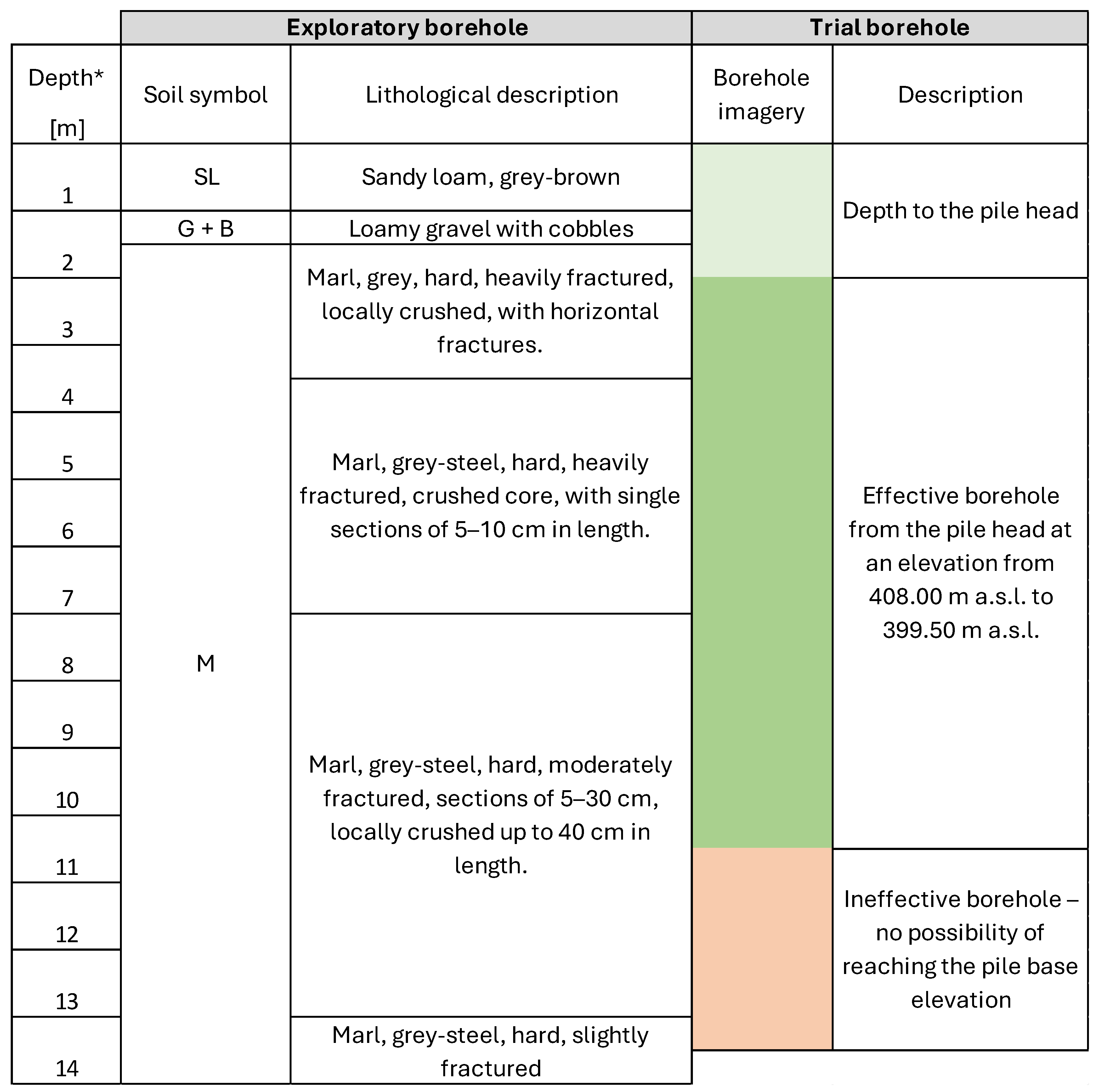
3.1. Boboszów Reservoir

Figure 9 provides simplified profiles of the boreholes drilled on the slope on the left bank of the Boboszów reservoir dam, with the most important results in terms of the identified type of soil, the rock quality designation (RQD) and the water absorption (“q”) or filtration coefficient (“k”).
Despite the relatively close proximity of the boreholes (approx. 25 m), considerable differences can be noted in the distribution of the layers constituting the geological profile at each location. This may be attributed, inter alia, to the significant difference in the elevation of the boreholes (approx. 13.5 m). In addition, different approaches and technologies were used to assess the permeability of the subsoil. For borehole P1, unit water absorption was determined at various depths; for boreholes R1 and R2, an average filtration coefficient was determined. Regardless of this, the interpretation of these results based on the Lugeon coefficient for water absorption [26] or Pazdra’s classification for the filtration coefficient [27] classifies the subsoil in these locations as moderately water-absorbent or poorly permeable. Furthermore, the use of Wieczysty’s formula (k = 2q [m/day]) [28] for the water absorption results at location P1 yields similar filtration coefficient values to those at points R1 and R2. Based on Deere’s classification [29,30], the rock-quality designation (RQD) provides information about the rock mass quality. In borehole P1, the entire depth showed very poor quality (with a RQD between 0 and 25%). For boreholes R1 and R2, very poor to poor quality (with a RQD between 26 and 50%) was identified for 12 m of the R1 core and 9 m of the R2 core. This indicates significant rock mass fracturing; combined with steep slopes and moderate water permeability, this factor could have indeed affected the stability of the dam.

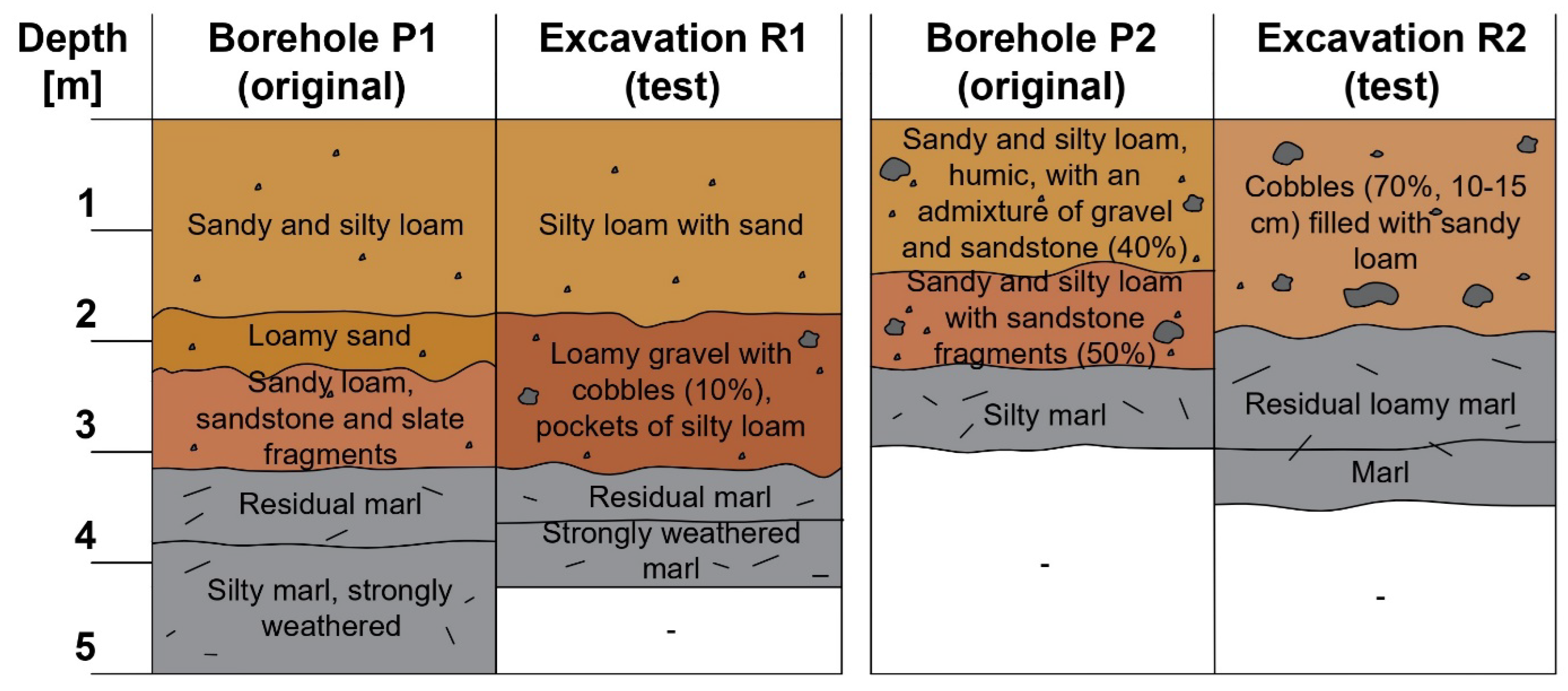
3.2. Roztoki Bystrzyckie Reservoir

Figure 10 shows a simplified profile of a borehole drilled near the planned anti-filtration screen and the results of a trial borehole drilled to assess the feasibility of installing piles in this location using the CFA technology. Table 4 shows the characteristic parameters determined at the planning stage for marls located approximately 11 m below ground level in the area of the Roztoki Bystrzyckie reservoir dam [23].
As indicated in the description of the trial borehole drilling, significant drilling resistance was encountered as quickly as at around an elevation of 408 m a.s.l. (depth of 2 m), suggesting that the roof of the first layer of marl was reached. From an elevation of 404 m a.s.l. (depth of 6 m), an additional slowdown in drilling occurred. The drilling ultimately stopped at approximately 399.50 m a.s.l. (depth of 10.5 m), because after 16 min of operation the hydraulic pressure at the drilling head had increased to about 270 bar and the piling rig was unable to continue. It is vital to emphasise that the subsoil had not yet undergone grouting, a procedure that would have further strengthened the soil 1.3 m above the pile base.

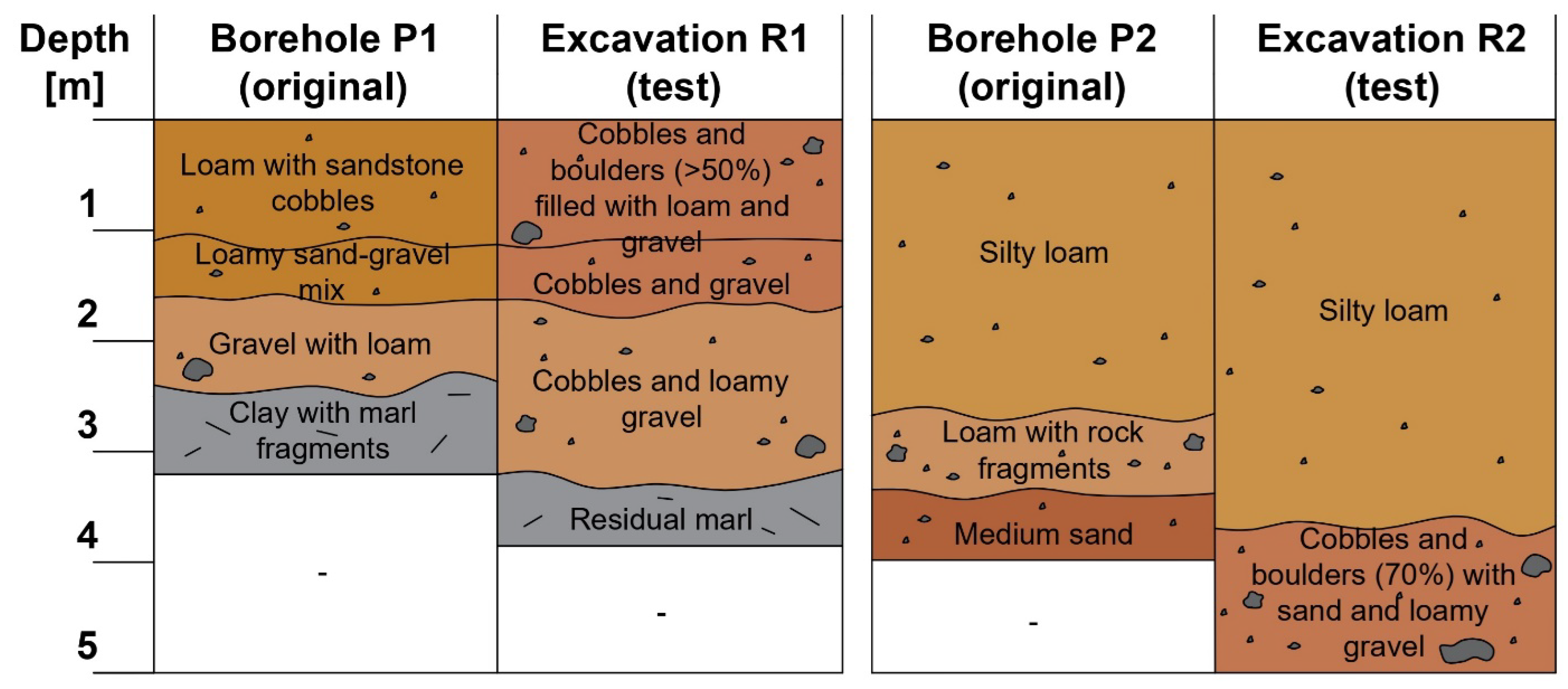
3.3. Krosnowice Reservoir

Figure 11 shows profiles illustrating the depth of the Cretaceous layer (marl) in a cross-section, based on the original investigations (D1–D10) and follow-up investigations (C1–C6). Furthermore, each point is labelled with the compressive strength (Rc) and Rock Quality Designation (RQD) values obtained at the depth of the layer closest to the roof. To illustrate the nature of the rock cores in the control survey, Figure 12 and Figure 13 show the soil extracted at points C2 and C3 from the top of the marl layer.
Analysing the profile in Figure 9, the difference in the depth of the Cretaceous layer roof in both compared profiles is undeniable. Based on the results of the follow-up investigations, the rocks (marl) in profiles C1 to C6 are located on average 3.25 m lower than in the original investigations, with the greatest difference of approx. 6 m at point C2. It is also important to consider the result obtained for point C6, which is located in the D1–D10 profile line. Irrespective of this location, the depth of the marl layer roof clearly deviates from the depth that would be predicted by interpolation between points D6 and D7. This may confirm the complex geological structure beneath the dam body and no clear boundary between rock debris and highly fractured marl or suggest some differences in the interpretation of the soil type in the obtained samples. The compressive strength in the original investigations was determined at one point only, i.e., D4, but this result correlates with the results of the follow-up investigations, demonstrating the very low strength of the rocks in the upper zone of the layer [29]. Similarly, the RQD parameter obtained in both investigations indicates a very poor rock mass quality, with a value of 0% at most points.
Figure 14, Figure 15 and Figure 16 provide an overview of selected results of the geological surveys of the deposits in the Krosnowice reservoir basin, categorised by two different technologies: boreholes drilled at the project planning stage and excavations serving as follow-up investigations [31,32]. To illustrate the nature of the soil in the deposits, a photograph taken in excavation R3 is shown in Figure 17.
In the first place, it should be noted that the total number of boreholes drilled directly in the area of deposits no. 1 and no. 2 (nine and three boreholes, respectively, in areas of approx. 7.5 and 2.5 ha) is small relative to their surface area; also, no borehole was drilled in the area of deposit no. 3. Most importantly, however, the compiled results of the investigations reveal noticeable differences in the type of soil at a given depth; this is also true for the boreholes and excavations made in exactly the same location. At point no. 1, where the original investigations identified loamy sand and sandy loam, the follow-up investigations revealed mainly gravel with cobbles, with the presence of silty loam being limited to some pockets. Similarly, in the cases of points nos. 2, 3, and 5, the excavations revealed a markedly stronger presence of gravel and cobbles compared to the results of the boreholes, suggesting lower-than-expected deposits in this location. Conversely, in the case of deposit no. 3, the boreholes drilled in the vicinity (particularly borehole no. P5) suggested a low potential for obtaining material suitable for the dam body. However, excavations R5 and R6 made directly within the deposit revealed the presence of valuable loam immediately beneath the surface.

3.4. Szalejów Górny Reservoir

Figure 18 shows profiles illustrating the depth of the Cretaceous layer (sandstone or marl) in a cross-section, based on the original investigations (D1–D10) and follow-up investigations (C1–C16). Furthermore, each point is labelled with the compressive strength (Rc) and Rock Quality Designation (RQD) values obtained at the depth of the layer closest to the roof. To illustrate the nature of the rock cores in the control survey, Figure 19 and Figure 20 show the soil extracted at points C2 and C3 from the top of the marl or sandstone layer.
As in the case of the Krosnowice reservoir, the difference in the depth of the Cretaceous layer roof in the three compared profiles is undeniable. Based on the results of the follow-up investigations, the rocks (marl or sandstone) in profiles C8 to C7 are located on average 3.46 m lower than in the original investigations, with the greatest difference of approx. 18.9 m at point C6. In the C9–C16 profile, the average is 3.01 m, with the greatest difference being 16.9 m at point C15. In this case, there is a noticeable difference between the eastern and western parts of the dam. In the former, the follow-up investigations indeed indicated a significantly deeper position of the rock formations. On the opposite side, however, the situation is reversed, with the marl or sandstone roof being located 6.75 m and 1.8 m (for points C1 and C9, respectively) above the levels determined in the original investigations. In this case, it is also important to take note of the lack of a clear boundary between the rock debris and the highly fractured marl or some differences in the interpretation of the soil type in the obtained samples. The compressive strength values from the original investigations are higher than those determined in the follow-up investigations; however, they still indicate very low rock strength in the upper zone of the layer [31]. The RQD parameter was not determined during the original investigations; it was established for the samples from the test boreholes. Highly variable, the results show no clear correlation, confirming the complex geological structure beneath the dam body and indicating that the roof of the Cretaceous layer may locally have both very good and very poor rock mass quality.
Figure 21, Figure 22 and Figure 23 provide an overview of selected results of the geological surveys of deposits in the Szalejów Górny reservoir basin, categorised by two different technologies: boreholes drilled at the project planning stage and excavations serving as follow-up investigations [33,34]. To illustrate the nature of the soil in the deposits, a photograph taken in excavation R4 is shown in Figure 24.
Although a significantly higher number of exploratory boreholes were drilled in the basin area of the Szalejów Górny reservoir and directly on the deposits, the compiled results of the investigations (obtained using different technologies) exhibit noticeable differences in the type of soil at given depths, as is the case with the Krosnowice reservoir. Whereas in location no. 2, the difference relates mainly to the depth of the silty loam bottom, in points 1 and 3, the presence of material contaminated with cobbles and boulders in excess of 50% was detected almost directly below the ground surface, something that was not revealed by the original measurements. Such layers are not suitable for any reasonable use in the construction of a dam body embankment. Their exact location, which could not be precisely inferred from the boreholes, was also identified in other locations. The follow-up investigations also confirmed no presence of a medium sand layer at point no. 2 or sandy loam at point no. 3, suggesting that the borehole had been drilled at the site of a local geological anomaly.

4. Discussion

When analysing the importance of the Rock Quality Designation (RQD) index as a tool for assessing the quality of the rock mass in the context of hydro-engineering projects (including the construction of backhoes), it should be pointed out that it has been repeatedly confirmed in the literature.A low RQD value indicates high fracturing of the rock mass, which can lead to intensification of filtration processes, especially under conditions of high ordinate differences and an elevated groundwater table. The high number of fractures and low cohesiveness of the rock mass significantly reduce its ability to counteract filtration and promote the development of filtration channels, which in the case of dams can result in localised internal erosion and slope destabilisation [35]. It is emphasised that, especially in areas with low RQD, the use of an extensive infiltration screen system or sealing injections should be considered. Furthermore, other studies have shown that variability in RQD within small spatial distances can lead to an underestimation of the risk of excessive soil filtration if the borehole grid is not adequately compacted [36]. Thus, the interpretation of rock mass quality should not only be local but also contextual, taking into account terrain and potential water flow directions. The use of RQD as one of the main criteria for assessing filtration risk can thus directly influence design decisions on the type and extent of protection required. In the case of Boboszów reservoir remains unclear is whether the destruction of the left bank of the dam would have occurred in the event of heavy rainfall after the construction work was completed, when the proper loading of this section with the entire weight of the soil mass might have protected it from exposure to filtration. The geological investigation conducted at point P1 at the project planning stage correctly identified the poor quality of the rock mass. It is, however, reasonable to assume that a higher density of boreholes at this location would have allowed for a clear assessment of the water filtration risks in this area and could have, as far as possible, induced the designer to make an earlier decision to extend the scope of the anti-filtration measures. The extension ultimately took placed based on the follow-up investigations.
In the context of the Roztoki Bystrzyckie reservoir incident, the parameters listed in Table 4 do not indicate any exceptional strength of the marls in the subsoil, which are inherently characterised by low strength and bearing capacity and impaired workability (related, among other things, to their high plasticity and sensitivity to moisture [37]. Quite the contrary, their compressive strength should be considered to be very low [38]. However, while the exploratory borehole was drilled with a diameter of 93 mm [23] the project provided for the installation of CFA piles with a diameter of 600 mm. It ultimately proved impossible to drill such a wide borehole using equipment suitable for the adopted technology in the deeper marl zone and along the entire length of the anti-filtration screen. In this case, a higher density of exploratory boreholes at the planning stage would have provided no additional data to facilitate making a decision on the optimal length of the CFA piles. Such information can be obtained only through trial boreholes using the intended equipment and drill diameter along the planned anti-filtration screen route. This method should be considered during the preliminary geological surveys of the project site and in the event of identifying hard subsoil in the anti-filtration screen profile. As a last resort, this situation may provide grounds for the designer to make a preemptive decision to extend the soil sealing zone using low-pressure grouting technology, at the expense of the length of the CFA pile wall; a solution that proved effective during the construction of the Roztoki Bystrzyckie reservoir.
Accurate mapping of the boundaries of geological strata is crucial for assessing the foundation conditions of a dam (which showed the issue concerning Krosnowice and Szalejów Górny reservoirs), as the different rock formations exhibit different geotechnical and hydrogeological properties. Cretaceous limestones and marls can differ in cohesion, porosity or susceptibility to erosion, among other things, so that inaccurate determination of their extent can lead to misinterpretation of the stability of the foundation [39]. Errors in interpolating geological data between boreholes presents another challenge—with typical inter-borehole distances of 10–50 m, the geological profile between points is unknown and must be inferred from experience or model assumptions [40]. The limited amount of data results in a high degree of uncertainty in the representation of geological strata, which ultimately makes design decisions difficult. Even with many boreholes, the degree of uncertainty persists and the consequences of incorrect predictions can be catastrophic. In doing so, it should be emphasised that the boundaries of geological layers generally have the highest uncertainty in models [41]. For this reason, key decisions—such as the foundation depth of the dam body—must be based on the most accurate, robust ground model possible, taking this risk into account. The compiled results indicate that the initial decision to construct the dam body directly on the roof of the Cretaceous layer and to use the profile determined using boreholes along the dam axis as a determinant of soil replacement depth was a controversial one. The original investigations indicated that the roof of the marl layer might have insufficient bearing capacity, requiring additional deepening of the embankment body until reaching a layer with the appropriate parameters, which was confirmed in situ. The follow-up investigations further revealed a greater depth of the marl layer than initially expected in the eastern section of the dam. It can thus be concluded that a higher density of boreholes drilled directly in the area of the dam body would have allowed for a more accurate estimation of the required embankment foundation depth and, hence, a more precise calculation of the soil volume needed to be extracted from the deposits. Many geotechnical problems similar to those identified in the present case study have also been documented in other regions worldwide. In the Alpine foreland (e.g., the Kaunertal Valley, Austria), significant variability of glaciofluvial deposits has been observed even over short distances, complicating the interpretation of borehole data and potentially necessitating unforeseen design adjustments [42]. In karst areas (e.g., Montejaque, Spain), an extensive network of karst voids was found to prevent the reservoir from being filled, despite prior investigations and grouting works [43]. A global analysis of leakage in karst reservoirs (e.g., in China) demonstrated the need for costly remedial measures or permanent sealing interventions [44]. Recent research indicates that combining borehole investigations with geophysical techniques enables more effective identification of potential leakage zones. In recent years, electrical resistivity tomography (ERT) has been increasingly employed to provide detailed mapping of horizontal and vertical distributions of zones with varying electrical conductivity, indicative of groundwater presence, karst voids, or loosened seepage zones. Another example is the application of audio-frequency magnetotellurics (AMT), which was used, for instance, to investigate the Yibasan reservoir in Yunnan Province, China, allowing the identification of 40–60 m wide low-resistivity zones interpreted as karst conduits and leakage pathways [45].
The different survey technology involving the exploration of deposits for the construction of the Krosnowice and Szalejów Górny dams was associated with significant differences in results. The boreholes led to the extraction of soil cores with a diameter of 8 cm [24]. Considering the complex subsoil structure of the reservoir basin, a borehole may have encountered a local anomaly, inaccurately reflecting the overall deposit structure [46]. By contrast, excavations, where soil is obtained from a hole measuring up to approx. 3 × 3 m, involve only a minimal risk of encountering a localised anomaly. Moreover, they allow the percentage of the rock fraction and cobbles in a given layer to be determined with greater accuracy. This means that excavations should be deemed more effective as investigations for assessing the volume of soil deposits that lie relatively close to the surface [47]. Large-scale excavations could, however, be difficult to organise at the project planning stage, given that, at this point, the properties within the reservoir basin are usually not yet owned by the developer and are sometimes still being used by people, for instance, for agricultural purposes. Using heavy equipment and organising large-scale excavations in such an area could give rise to social unrest and generate extra costs related to potential compensations. Nevertheless, given the significance of identifying the volume of deposits available for the construction of earthen dams, it would be advisable to consider more frequently combining both subsoil investigation technologies: boreholes as the foundation of geological surveys and excavations as a supplementary method. It should also be noted that, in engineering geology, the selection of borehole locations is a key element of subsurface investigation planning, directly influencing the quality of the geological model and the risk of misinterpretation. Two contrasting approaches—random placement and representative placement—differ in both purpose and implications. Random selection of locations, used mainly in statistical studies, helps to avoid spatial bias but may fail to capture zones of critical engineering importance (e.g., dam axes, fault zones, karst depressions). In contrast, the representative approach involves deliberate placement of investigation points based on available knowledge of the geological structure, landform, geophysical survey results, and the planned locations of structural loads. In engineering practice, a mixed strategy is generally preferred: a grid of primary boreholes is laid out in a regular pattern (e.g., parallel to the construction axis or along geophysical survey profiles), while additional borehole locations are determined adaptively—in areas of anomalies, facies changes, or suspected voids. Such a strategy increases the representativeness of the results while reducing the risk of systematic spatial errors [48]. According to USACE guidelines (2004), the distribution of boreholes should be adjusted to the complexity of the geological conditions and the level of project risk, with a denser drilling grid recommended in areas of potential discontinuities or known tectonic structures. Particular attention should be paid to areas with heterogeneous subsurface conditions, where point data may not accurately reflect the actual distribution of layers and voids [11].
Despite the availability of modern subsurface investigation methods, a significant number of hydrotechnical projects still experience construction issues due to underestimated geological conditions. A review of the literature and project data highlights several recurring causes of this situation: (1) budget constraints, (2) time and procedural constraints, (3) fragmentation of responsibilities, and (4) technological and interpretative challenges. In engineering practice, expenditures on site investigations are often underestimated relative to actual needs—frequently amounting to <0.5–1% of the total project value, even though institutions such as the World Bank recommend a minimum level of 3–5%, particularly in challenging settings (e.g., karst or tectonically active areas). Underfunding results in overly sparse drilling grids, the omission of geophysical surveys, and oversimplifications in geological modelling [49]. Failure to align the scope of geotechnical investigations with the geological complexity and sensitivity of the project leads to underestimation of risks, which, in turn, increases the likelihood of structural errors and costly design revisions at later stages [50]. Schedule pressure (e.g., stemming from financing plans or procurement deadlines) often results in shortened investigation phases and omission of seasonal or long-term monitoring. In some cases, design decisions are made before the geological ground model has been fully developed [51]. Moreover, the client, the geotechnical investigation contractor, and the designer often operate independently, which hinders data integration and comprehensive interpretation. The lack of unified geological risk management increases the risk of systemic errors [52]. In karst or geologically complex areas, conventional point-drilling methods are often insufficient. Where complementary techniques (ERT, AMT, GPR) are not employed, the resulting geological model carries significant uncertainty. Additionally, the lack of standardization in data interpretation hinders comparability across projects [45,53]. Effective risk management requires not only more extensive geological data, but also a structured approach to their assessment, including hazard prioritization and the selection of mitigation strategies based on potential consequences [54].
It is also important to emphasize the potential cost increases resulting from the identification of unforeseen ground conditions. Geotechnical problems in projects are a key driver of claims, contract modifications, as well as budget and schedule overruns [55]. As demonstrated in analyses of hydrotechnical projects in China (Guangxi, a karst province), among 644 reservoirs requiring leakage repairs, the average cost of reconstructing seepage control systems significantly increased the total construction costs [44]. Similarly, in the case of the Montejaque reservoir (Spain), the loss of functionality due to unforeseen karst voids led to the complete failure of the investment, as the reservoir was never filled [43].
A World Bank report indicates that the average cost overrun in hydroelectric projects can reach 27%, with schedules extended by approximately 28%, which is correlated with insufficient geotechnical investigation [56]. Experience from Australian dams shows a median cost overrun of 49%, and an average as high as 120%, largely due to unforeseen ground conditions [49]. The most recent meta-analyses of dam projects completed after 2000 support these observations, reporting an average cost increase of 33% and a schedule delay of 18% [57].
Optimization of geological investigations (both geotechnical and geophysical) at the investment planning stage brings significant economic and technical benefits. Well-designed subsurface investigations reduce uncertainty regarding ground and groundwater conditions, which translates into lower risk of costly design modifications, delays, and failures during construction and operation. The financial benefits of thorough geological investigations far outweigh their costs, as reliable geotechnical data enable the design of safer and more economical foundations, while expenditures on investigations usually represent only a small fraction of the total investment budget [58]. According to the Geotechnical Engineering Committee of the U.S. National Research Council (NRC), as early as the 1980s it was recommended to allocate at least 3% of the total project cost to comprehensive geological–engineering investigations (particularly for underground works, tunnels, and dams), which remains economically justified given the potential consequences of inadequate investigations [59]. More recent studies have proposed probabilistic frameworks for cost–benefit analysis (CBA) of geotechnical investigations, taking into account the uncertainty of ground parameters and the influence of investigation scope on the total project cost. These models demonstrate that optimal investment in site investigations can substantially minimize overall project costs, even if it involves higher upfront expenditure [60]. With reference to the construction of the Krosnowice and Szalejów Górny reservoirs, the actual costs of these investments significantly exceeded initial estimates. In the case of Krosnowice, the final cost was approximately USD 49 million (originally around USD 22.5 million, an increase of 118%), while for Szalejów Górny the cost rose to approximately USD 105 million (originally about USD 41 million, an increase of 156%). Although it was not precisely calculated what proportion of the cost increase was due to the identification of ground conditions, given the nature of the design changes implemented and the associated project delays, it can be assumed that up to 80% of the cost increase may be attributed to this factor. In light of this, it would have been economically rational to allocate the aforementioned 3% of the total investment cost to geological investigations and to extend them with complementary geophysical techniques. These circumstances clearly demonstrate that, regardless of the region, comprehensive and multi-method (incorporating various technologies) geological–engineering investigations are crucial for the design and construction of dry flood-control reservoirs.przeciwpowodziowych.

5. Conclusions

This case study analysed the problems that arise when different soil conditions are identified at the construction site of dammed reservoirs, making it possible to formulate conclusions and recommendations regarding the specific circumstances of each project.

5.1. Boboszów Reservoir

Intense rainfall caused damage to the dam embankment under construction, giving rise to concerns about insufficient anti-filtration protection between the dam and the fractured rock mass. The geological investigations in this area consisted of only one borehole at a distance of approx. 35 m from the construction boundary. In order to verify the results, additional boreholes were drilled closer to the dam. Using the RQD and the filtration coefficient, the permeability and the poor quality of the rock mass, as established in the original investigations, were confirmed. A higher density of boreholes at this location would have allowed for a clear assessment of the water filtration risks in this area and could have, as far as possible, induced the designer to make an earlier decision to extend the scope of the anti-filtration measures.

5.2. Roztoki Bystrzyckie Reservoir

One of the designed watertight elements of the structure was a barrier made of CFA piles (ø60 cm) with a length of 11.5 m, placed above low-pressure grouting. The follow-up investigations excluded their feasibility. The original exploratory borehole indicated the presence of marls in the subsoil; despite their low compressive strength, however, deep drilling with CFA piles proved to be impossible. In this case, a higher density of exploratory boreholes at the planning stage would have provided no additional data to facilitate making a decision on the optimal length of the CFA piles. Such information can be obtained only through trial boreholes using the intended equipment and drill diameter along the planned anti-filtration screen route.

5.3. Krosnowice and Szalejów Górny Reservoir

The dams of both reservoirs were designed to be founded on the roof of the Cretaceous layer, particularly on rock formations (marl or sandstone). At the construction stage, it was noted, however, that the load-bearing soils were located deeper than the elevation designated as the soil replacement line. This observation meant that it was necessary to explore more deposits and to identify them with greater precision. The follow-up investigations confirmed a deeper position of the Cretaceous layer roof, 3.25 m and 3.24 m (for Krosnowice and Szalejów Górny, respectively) on average below the line determined in the original investigations. For Krosnowice, the depth of the test profile is below the original depth at each of the selected points (maximum of 6.0 m). In the case of Szalejów Górny, by contrast, it locally exceeds the original depth (by a maximum of 6.75 m), while it is 18.9 m below the original depth on the opposite side of the dam. The indicated results and the values of the Rc and RQD parameters indicate a complex geological structure beneath the dam body and a potential lack of a clear boundary between the rock debris and highly fractured marl. It can be concluded that a higher density of boreholes drilled directly in the area of the dam body would have allowed for a more accurate estimation of the required embankment foundation depth and, hence, a more precise calculation of the soil volume needed to be extracted from the deposits. The follow-up investigations of the deposits (through extensive local excavations) have demonstrated primarily that excavations can be deemed a more effective method than boreholes (ø8 cm) for assessing the volume and quality of soil deposits located relatively shallow below the ground surface. However, since excavations may prove difficult to implement at the project planning stage, they should be viewed as supplementary to more extensive investigations based on boreholes.

Supplementary Materials

The following supporting information can be downloaded at: https://www.mdpi.com/article/10.3390/app15147811/s1, Supplementary Figure S1: Longitudinal geological–engineering cross-section along the axis of the Krosnowice reservoir dam; Supplementary Figure S2: Longitudinal geological–engineering cross-section along the axis of the Szalejów Górny reservoir dam.

Author Contributions

Conceptualisation, M.P. and M.W.; Methodology, M.P.; Software, M.P. and G.Ł.; Validation, M.W.; Formal analysis, M.P.; Investigation, M.P., M.W. and G.Ł.; Resources, M.P. and G.Ł.; Data curation, M.P. and G.Ł.; Writing—original draft preparation, M.P.; Writing—review and editing, M.P. and M.W.; Visualisation, M.P. and G.Ł.; Supervision, M.W.; Project administration, M.P.; Funding acquisition, M.P. and M.W. All authors have read and agreed to the published version of the manuscript.

Funding

Financed by the Wrocław University of Environmental and Life Sciences and Ministry of Education and Science.

Institutional Review Board Statement

Not applicable.

Informed Consent Statement

Not applicable.

Data Availability Statement

The original contributions presented in the study are included in the article/Supplementary Materials, further inquiries can be directed to the corresponding author.

Acknowledgments

As Maksymilian Połomski is student in the 6th edition of the implementation doctorate programme, the authors would like to express their gratitude to the Ministry of Education and Science for its support in carrying out their research.

Conflicts of Interest

The authors declare no conflicts of interest.

References

  1. Połomski, M.; Wiatkowski, M. The Use of Lime for Drainage of Cohesive Soils Built into Hydraulic Engineering Embankments. Water 2022, 14, 3700. [Google Scholar] [CrossRef]
  2. Połomski, M.; Wiatkowski, M. Impounding Reservoirs, Benefits and Risks: A Review of Environmental and Technical Aspects of Construction and Operation. Sustainability 2023, 15, 16020. [Google Scholar] [CrossRef]
  3. Regulation of the Minister of Transport, Construction and Maritime Economy of April 25, 2012 on Determining Geotechnical Conditions for the Foundation of Building Structures. Available online: https://isap.sejm.gov.pl/isap.nsf/download.xsp/WDU20120000463/O/D20120463.pdf (accessed on 1 April 2025).
  4. PN-B-02480:1986; Grunty Budowlane. Okreslenia Symbole Podzial i Opis Gruntow. Polish Committee for Standardization: Warsaw, Poland, 1986.
  5. PN-B-02481:1998; Geotechnika. Terminologia Podstawowa Symbole Literowe Jednostki Miar. Polish Committee for Standardization: Warsaw, Poland, 1998.
  6. PN-B-03020:1981; Building Soils—Foundation Bases—Static Calculation and Design. Polish Committee for Standardization: Warsaw, Poland, 1981.
  7. PN-B-04452:2002; Geotechnics—Field Tests. Polish Committee for Standardization: Warsaw, Poland, 2002.
  8. PN-B-04481:1998; Grunty Budowlane. Badania Próbek Gruntu. Polish Committee for Standardization: Warsaw, Poland, 1998.
  9. PN-EN 206-1:2003; Concrete—Part 1: Specification, Performance, Production and Confo. Polish Committee for Standardization: Warsaw, Poland, 2003.
  10. PN-EN ISO 14689-1:2006; Geotechnical Investigation and Testing—Identification and Classification of Rock—Part 1: Identification and Description. Polish Committee for Standardization: Warsaw, Poland, 2006.
  11. US Army Corps of Engineers. General Design and Construction Considerations for Earth and Rock-Fill Dams; EM 1110-2-2300; US Army Corps of Engineers: Washington, DC, USA, 2004; Available online: https://www.publications.usace.army.mil/portals/76/publications/engineermanuals/em_1110-2-2300.pdf (accessed on 1 April 2025).
  12. Wiłun, Z. Outline of Geotechnics; WKiŁ: Warszawa, Poland, 1987. [Google Scholar]
  13. Sousa, L.M.O.; Martín Freire-Lista, D.; Carter, R.; Al-Na’imi, F. Petrographic and petrophysical characterisation and structural function of the heritage stones in Fuwairit Archaeological Site (NE Qatar): Implications for heritage conservation. Materials 2023, 16, 4927. [Google Scholar] [CrossRef]
  14. Zhang, L.M.; Xu, Y.; Jia, J.S. Analysis of earth dam failures: A database approach. Georisk Assess. Manag. Risk Eng. Syst. Geohazards 2009, 3, 184–189. [Google Scholar] [CrossRef]
  15. Strzałkowski, P.; Köken, E.; Kaźmierczak, U. Estimation of cohesion for intact rock materials using regression and soft computing analyses. J. Rock Mech. Geotech. Eng. 2023, 15, 789–802. [Google Scholar] [CrossRef]
  16. Köken, E.; Kadakcı Koca, T. A comparative study to estimate the Mode I fracture toughness of rocks using several soft computing techniques. Bull. Eng. Geol. Environ. 2022, 81, 55. [Google Scholar] [CrossRef]
  17. Czyżewski, K. Earth Dams; Arkady: Warszawa, Poland, 1973. [Google Scholar]
  18. Strzałkowski, P.; Sousa, L.M.O.; Köken, E. Guidelines for natural stone products in connection with European standards. Materials 2023, 16, 6885. [Google Scholar] [CrossRef]
  19. Mieszkowski, R.; Kowalczyk, S.; Barański, M.; Szczepański, T. The use of geophysical methods to identify the roof of cohesive soils and the designation of zones of suffusion relaxation in the body of an earth dam. Zesz. Nauk. Inst. Gospod. Surowcami Miner. Energią. PAN 2014, 86, 167–180. [Google Scholar]
  20. Strzałkowski, P.; Bęś, P.; Szóstak, M.; Napiórkowski, M. Application of Virtual Reality (VR) Technology in Mining and Civil Engineering. Sustainability 2024, 16, 2239. [Google Scholar] [CrossRef]
  21. Stupnicka, E. Regional Geology of Poland; University of Warsaw Publishing House: Warszawa, Poland, 2007. [Google Scholar]
  22. ARCADIS. Geological and Engineering Documentation of the Designed Boboszów Reservoir on the Nysa Kłodzka River. 2012; Unpublished Technical Report. [Google Scholar]
  23. PROXIMA. Geological and Engineering Documentation of the Designed Roztoki Bystrzyckie Reservoir on the Goworówka River. 2014; Unpublished Technical Report. [Google Scholar]
  24. HYDROGEO. Geological and Engineering Documentation of the Designed Krosnowice Reservoir on the Duna Stream. 2014; Unpublished Technical Report. [Google Scholar]
  25. Integrated Management Services; PROXIMA; Przedsiębiorstwo Geologiczne. Geological and Engineering Documentation of the designed Krosnowice reservoir on the Duna Stream. 2012; Unpublished Technical Report. [Google Scholar]
  26. Uromeihy, A.; Farrokhi, R. Evaluating grout ability at the Kamal-Saleh Dam based on Lugeon tests. Bull. Eng. Geol. Environ. 2012, 71, 215–219. [Google Scholar] [CrossRef]
  27. Jaworksa-Szulc, B. Assessment of groundwater recharge in the Kashubian Lake District using various methods and various scales of study. Przegląd Geol. 2015, 63, 762–768. [Google Scholar]
  28. Wieczysty, A. Engineering Hydrogeology; PWN: Warszawa, Poland; Kraków, Poland, 1970. [Google Scholar]
  29. PKP Polish Railway Lines. Subsoil Testing Guidelines Land for Needs Construction and Modernization Railway Infrastructure; PKP Polish Railway Lines: Warszawa, Poland, 2016. [Google Scholar]
  30. Łętka, T.; Pilecki, Z. A Method for Assessing the Degree of Cracking in a Rock Medium Using a Borehole GPR; Publishing house of the Institute of Mineral Resources and Energy Management of the Polish Academy of Sciences: Kraków, Poland, 2016. [Google Scholar]
  31. GHEKO. Report on Control Tests Carried out on Deposits of Soil Material for the Construction of the Dam of the Krosnowice Flood Control Reservoir. 2019; Unpublished Technical Report. [Google Scholar]
  32. Hawrysz, M.; Stróżyk, J.; Hawrysz, P. Opinion on the abundance of soil material deposits for the formation of earth buildings in the Krosnowice Flood Control Reservoir Area. 2019; Unpublished Technical Report. [Google Scholar]
  33. GHEKO. Report on Control Tests Carried out on Deposits of Soil Material for the Construction of the Dam of the Szalejów Górny Flood Control Reservoir. 2019; Unpublished Technical Report. [Google Scholar]
  34. Hawrysz, M.; Stróżyk, J.; Hawrysz, P. Opinion on the abundance of soil material deposits for the formation of earth buildings in the Szalejów Górny Flood Control Reservoir Area. 2019; Unpublished Technical Report. [Google Scholar]
  35. Khurshid, M.N.; Khan, A.H.; Rehman, Z.u.; Chaudhary, T.S. The Evaluation of Rock Mass Characteristics against Seepage for Sustainable Infrastructure Development. Sustainability 2022, 14, 10109. [Google Scholar] [CrossRef]
  36. Ding, Q.; Wang, F.; Chen, J.; Wang, M.; Zhang, X. Research on Generalized RQD of Rock Mass Based on 3D Slope Model Established by Digital Close-Range Photogrammetry. Remote Sens. 2022, 14, 2275. [Google Scholar] [CrossRef]
  37. Mirzababaei, M.; Karimiazar, J.; Sharifi Teshnizi, E.; Arjmandzadeh, R.; Bahmani, S.H. Effect of Nano-Additives on the Strength and Durability Characteristics of Marl. Minerals 2021, 11, 1119. [Google Scholar] [CrossRef]
  38. Kamieński, M.; Skalmowski, W. Building and Road Stones; Geological Publishing Houses: Warszawa, Poland, 1957. [Google Scholar]
  39. Mitelman, A. Machine Learning Analysis of Borehole Data for Geotechnical Insights. Geotechnics 2024, 4, 1175–1188. [Google Scholar] [CrossRef]
  40. Ji, X.; Lu, X.; Guo, C.; Pei, W.; Xu, H. Predictions of Geological Interface Using Relevant Vector Machine with Borehole Data. Sustainability 2022, 14, 10122. [Google Scholar] [CrossRef]
  41. Li, H.; Wan, B.; Chu, D.; Wang, R.; Ma, G.; Fu, J.; Xiao, Z. Progressive Geological Modeling and Uncertainty Analysis Using Machine Learning. ISPRS Int. J. Geo-Inf. 2023, 12, 97. [Google Scholar] [CrossRef]
  42. Piermattei, L.; Heckmann, T.; Betz-Nutz, S.; Altmann, M.; Rom, J.; Fleischer, F.; Stark, M.; Haas, F.; Ressl, C.; Wimmer, M.H.; et al. Evolution of an Alpine Proglacial River during Seven Decades of Deglaciation. Earth Surf. Dyn. 2023, 11, 383–403. [Google Scholar] [CrossRef]
  43. Jiménez Gavilán, P.; Durán Valsero, J.J.; Carrasco Cantos, F.; López Geta, J.A.; Andreo Navarro, B. Análisis de la respuesta hidrodinámica de acuíferos carbonáticos de la Cordillera Bética occidental (Sur de España). Boletín Geológico Y Min. 2004, 115, 187–198. [Google Scholar]
  44. Stevanović, Z.; Milanović, P. Engineering Challenges in Karst. In Karst Without Boundaries; Stevanović, Z., Krešić, N., Kukurić, N., Eds.; CRC Press/Balkema: Leiden, The Netherlands, 2015; pp. 93–102. ISBN 9781138028668. Available online: https://scispace.com/pdf/engineering-challenges-in-karst-2fod011ydu.pdf (accessed on 1 April 2025).
  45. Zhang, W.; Pan, X.; Liang, J.; Zeng, J.; Song, C. Study on the Hydrogeological Structure of a Karst Subterranean River and Seepage of a Karst Reservoir: A Case Study of the Yibasan Reservoir in Yunnan Province, China. Water 2024, 16, 92. [Google Scholar] [CrossRef]
  46. Peng, M.-Q.; Qiu, Z.-C.; Shen, S.-L.; Li, Y.-C.; Zhou, J.-J.; Xu, H. Geotechnical Site Characterizations Using a Bayesian-Optimized Multi-Output Gaussian Process. Sustainability 2024, 16, 5759. [Google Scholar] [CrossRef]
  47. Del Fabbro, M.; Paronuzzi, P.; Bolla, A. Geotechnical Characterisation of Flysch-Derived Colluvial Soils from a Pre-Alpine Slope Affected by Recurrent Landslides. Geosciences 2024, 14, 115. [Google Scholar] [CrossRef]
  48. ISO 22475-1:2011; Geotechnical Investigation and Testing—Sampling Methods and Groundwater Measurements—Part 1: Technical Principles. ISO: Geneva, Switzerland, 2011. Available online: https://www.iso.org/standard/71002.html (accessed on 1 April 2025).
  49. World Bank. Good Practice Note on Dam Safety—Technical Note 2: Geotechnical Risk; World Bank: Washington, DC, USA, 2021; Available online: https://documents1.worldbank.org/curated/en/241051619161798594/pdf/Geotechnical-Risk.pdf (accessed on 1 April 2025).
  50. Gangrade, R.; Grasmick, J.; Trainor-Guitton, W.; Mooney, M. Risk-Based Methodology to Optimize Geotechnical Site Investigations in Tunnel Projects. Tunn. Undergr. Space Technol. 2022, 127, 104589. [Google Scholar] [CrossRef]
  51. European Large Geotechnical Institutes Platform (ELGIP). Reduction of Geotechnical Uncertainties for Infrastructure—Vision Paper; ELGIP: Brussels, Belgium, 2015; Available online: https://elgip.org/wp-content/uploads/2020/06/20151118-Vision-paper-Transport-Infrastructure.pdf (accessed on 1 April 2025).
  52. Thompson, B. The Benefits of Early Geotech Risk Mitigation; HKA Insights; HKA: London, UK, 2023; Available online: https://www.hka.com/article/geotech-risks/ (accessed on 1 April 2025).
  53. Tao, M.; Chen, X.; Cheng, Q.; Binley, A. Evaluating the Joint Use of GPR and ERT on Mapping Shallow Subsurface Features of Karst Critical Zone in Southwest China. Vadose Zone J. 2021, 21, e20172. [Google Scholar] [CrossRef]
  54. Gao, R.; Kuang, T.; Meng, X.; Huo, B. Effects of Ground Fracturing with Horizontal Fracture Plane on Rock Breakage Characteristics and Mine Pressure Control. Rock Mech. Rock. Eng. 2021, 54, 3229–3243. [Google Scholar] [CrossRef]
  55. Shrestha, P.P.; Neupane, K.P. Identification of Geotechnical-Related Problems Impacting Cost, Schedule, and Claims on Bridge Construction Projects. J. Leg. Aff. Disput. Resolut. Eng. Constr. 2020, 12, 04520005. [Google Scholar] [CrossRef]
  56. Hoek, E.; Palmieri, A. Geotechnical Risks on Large Civil Engineering Projects. In Proceedings of the Keynote address at International Association for Engineering Geologists Congress, Vancouver, BC, Canada, 21–25 September 1998; Available online: https://www.rocscience.com/assets/resources/learning/hoek/Geotechnical-Risks-on-Large-Civil-Engineering-Projects-1998.pdf (accessed on 1 April 2025).
  57. Flyvbjerg, B.; Bruzelius, N.; Rothengatter, W. Cost and Schedule Overruns in Large Hydropower Dams: An Assessment of Projects Completed since 2000. Int. J. Water Resour. Dev. 2019, 36, 865–887. [Google Scholar] [CrossRef]
  58. Temple, M.W.B.; Stukhart, G. Cost Effectiveness of Geotechnical Investigations. J. Manag. Eng. 1987, 3, 8–19. [Google Scholar] [CrossRef]
  59. Jaksa, M.B. Geotechnical Risk and Inadequate Site Investigations: A Case Study. Aust. Geomech. J. 2000, 35, 39–47. [Google Scholar]
  60. Merisalu, J.; Sundell, J.; Rosén, L. A Framework for Risk-Based Cost–Benefit Analysis for Decision Support on Hydrogeological Risks in Underground Construction. Geosciences 2021, 11, 82. [Google Scholar] [CrossRef]
Figure 1. Location of Boboszów, Roztoki Bystrzyckie, Krosnowice and Szalejów Górny reservoirs.
Applsci 15 07811 g001
Figure 2. Locations of the original borehole (P1) and test boreholes (R1, R2) in the area of the left bank of the Boboszów reservoir dam.
Applsci 15 07811 g002
Figure 3. Alternative technical solution to improve the safety of the Boboszów dammed reservoirs.
Applsci 15 07811 g003
Figure 4. Locations of the boreholes and route of the anti-filtration screen.
Applsci 15 07811 g004
Figure 5. Design solution for the watertight barrier of the Roztoki Bystrzyckie reservoir.
Applsci 15 07811 g005
Figure 6. Location of geological investigations (original and follow-up investigations) in the Krosnowice reservoir [24].
Applsci 15 07811 g006
Figure 7. Location of geological investigations (original and follow-up investigations) in the Szalejów Górny reservoir [25].
Applsci 15 07811 g007
Figure 8. Photograph of Deposit 2 area at the construction site of the Szalejów Górny reservoir.
Applsci 15 07811 g008
Figure 9. Summary of geological investigation results from boreholes P1, R1, and R2 near the left bank of the Boboszów reservoir dam [22].
Applsci 15 07811 g009
Figure 10. Summary of the exploratory borehole results with the trial borehole result for a CFA pile [23]. * From an elevation of 410.00 m a.s.l.
Applsci 15 07811 g010
Figure 11. Depth of the Cretaceous layer roof determined in the original and test cross-section in the dam body area of Krosnowice [24].
Applsci 15 07811 g011
Figure 12. Rock core at the C2 borehole point, Krosnowice reservoir.
Applsci 15 07811 g012
Figure 13. Rock core at the C3 borehole point, Krosnowice reservoir.
Applsci 15 07811 g013
Figure 14. Soil investigation results at points 1 and 2 within the Krosnowice reservoir basin.
Applsci 15 07811 g014
Figure 15. Soil investigation results at points 3 and 4 within the Krosnowice reservoir basin.
Applsci 15 07811 g015
Figure 16. Soil investigation results at points 5 and 6 within the Krosnowice reservoir basin.
Applsci 15 07811 g016
Figure 17. Photograph of excavation pit wall R3, Krosnowice reservoir.
Applsci 15 07811 g017
Figure 18. Depth of the Cretaceous layer roof determined in the original and follow-up cross-sections in the dam body area of Szalejów Górny [25].
Applsci 15 07811 g018
Figure 19. Rock core at the C2 borehole point, Szalejów Górny reservoir.
Applsci 15 07811 g019
Figure 20. Rock core at the C3 borehole point, Szalejów Górny reservoir.
Applsci 15 07811 g020
Figure 21. Soil investigation results at points 1 and 2 within the Szalejów Górny reservoir basin.
Applsci 15 07811 g021
Figure 22. Soil investigation results at points 3 and 4 within the Szalejów Górny reservoir basin.
Applsci 15 07811 g022
Figure 23. Soil investigation results at points 5 and 6 within the Szalejów Górny reservoir basin.
Applsci 15 07811 g023
Figure 24. Photograph of excavation pit wall R4, Szalejów Górny reservoir.
Applsci 15 07811 g024
Table 1. Basic parameters of soil planned for the dam body of the Boboszów and Roztoki Bystrzyckie reservoirs [22,23].
ParameterValue
Grain size0–5 mm
Silt fraction content0.9%
Clay fraction content5.8–9.7%
Bulk density of soil skeleton1.98–2.15 g/cm3
Filtration coefficientapprox. 9.5∙10−5
Organic matter content0–0.4%
Table 2. Parameters of the soil originally planned for the dam of the Szalejów Górny and Krosnowice reservoirs [24,25].
Description and LocationBulk Density
ρ [kg/m3]
Plasticity Index
IL [-]
Angle of Internal Friction Φ [°]Cohesion
C [kPa]
Szalejów—A2.0820.0511.030.0
Szalejów—B2.0010.358.020.0
Krosnowice—C2.0320.08417.018.9
A—silty loams, silty loams with sand, and sandy loams with fragments of crystalline rocks; B—silty loams with sand, silty loams and sandy loams with rock fragments and loam with sandstone cobbles; C—sandy loams, and sandy and silty loams in a hard-plastic state.
Table 3. Soil symbols.
SymbolDescriptionSymbolDescriptionSymbolDescription
SLSandy loamGGravelRDRock debris
SILSilty loamSGMSand and gravel mixBBoulders
SSLSandy and silty loamSGM(c)Sand and gravel mix with clay additionMsMudstone
LSLoamy sandFSFertile soilSsSandstone
SSSilty sandOMOrganic matterMMarl
FSFine sandEEmbankmentCsClaystone
Table 4. Characteristic parameters determined for marls located approximately 11 m below ground level in the area of the Roztoki Bystrzyckie reservoir dam [23].
Bulk Density *Specific DensityCompressive StrengthDeformation Modulus
[kg/dm3][kg/dm3][MPa][GPa]
2.402.735.801.00
Elastic ModulusPoisson’s RatioAngle of Int. FrictionCohesion
[GPa][-][°]MPa
4.460.0930.6515.95
* In natural moisture state.
Disclaimer/Publisher’s Note: The statements, opinions and data contained in all publications are solely those of the individual author(s) and contributor(s) and not of MDPI and/or the editor(s). MDPI and/or the editor(s) disclaim responsibility for any injury to people or property resulting from any ideas, methods, instructions or products referred to in the content.

