Article

Load Prediction Control Study of a Pitch Control System for Large Offshore Wind Turbines

1
School of Mechanical Engineering, Yanshan University, Qinhuangdao 066004, China
2
Sichuan Chuanrun Intelligent Fluid Technology Co., Ltd., Chengdu 610000, China
3
School of Mechanical and Electrical Engineering, Xinjiang Institute of Engineering, Urumqi 830023, China
4
Xinjiang Coal Mine Electromechanical Engineering Technology Research Center, Xinjiang Institute of Engineering, Urumqi 830023, China
*
Author to whom correspondence should be addressed.
Appl. Sci. 2025, 15(12), 6468; https://doi.org/10.3390/app15126468
Submission received: 24 March 2025 / Revised: 10 May 2025 / Accepted: 12 May 2025 / Published: 9 June 2025

Abstract

:
In recent years, the global demand for renewable energy has been steadily increasing, and offshore wind power generation technology has thus developed rapidly, with the optimization of the performance of the pitch control system, as a key technology to ensure the efficient and safe operation of wind turbines, becoming a research hotspot. Offshore wind turbines face complex environmental changes, particularly regarding the load perturbations caused by wind speed, wind direction, waves, and other factors, which have a significant impact on the stability and accuracy of the pitch control system. In order to reduce the impact of load disturbance on pitch accuracy, this paper proposes a pitch control strategy with load disturbance compensation. Firstly, the relationship between hydraulic cylinder displacement and pitch angle is analyzed; then, the mathematical model comparing hydraulic cylinder displacement, servo motor speed, and external load disturbance force is constructed; the hydraulic cylinder position control strategy with load disturbance compensation is proposed; and finally, the effectiveness of the control strategy is verified through simulations and experiments.

1. Introduction

With the growing global energy demand and increasing environmental protection awareness, the development of clean renewable energy has become a crucial component in national energy strategies worldwide [1]. As an efficient and eco-friendly energy source, offshore wind power has attracted significant attention and experienced rapid development in recent years owing to its abundant wind resources and high power generation efficiency [2,3]. To ensure operational safety and stable power output from wind turbines, variable pitch technology has emerged as an essential solution [4].
The pitch control system, a core component of wind turbine control systems, regulates generator power output by adjusting blade angles [5]. This mechanism ensures optimal operational efficiency across varying wind conditions while minimizing structural loads [6]. Extensive scholarly research has been conducted on pitch control methodologies [7,8,9,10]. Contemporary wind turbines typically employ two pitch system configurations: servo motor-driven systems and valve-controlled hydraulic systems. Servo motor systems offer compact dimensions and high cleanliness levels, although their limited torque output necessitates their coupling with high-ratio gearboxes. Conversely, hydraulic valve-controlled systems readily achieve high torque output but suffer from significant overflow losses, poor contamination resistance, and large physical footprints. Emerging as an innovative solution, electro-hydraulic servo pump-controlled pitch systems combine the advantages of both technologies. Characterized by simplified architecture and reduced energy consumption, these systems demonstrate compact sizing, zero overflow loss, and exceptional power-to-weight ratios [11,12]. Utilizing hydraulic pumps to drive cylinders for precise blade angle adjustment, this technology effectively manages high-load scenarios and turbulent wind conditions through enhanced dynamic response and operational stability [13,14]. Nevertheless, offshore wind turbines face unique operational challenges. Transient wind speed fluctuations and gust events induce abrupt changes in blade attack angles, while wave-induced dynamic loads propagate through tower structures to the pitch system [15,16]. Additional disturbances originate from blade elastic deformation, tower oscillations, and drive train dynamics [17,18]. Accurate prediction and mitigation of these load variations have consequently become critical research priorities for advancing pump-controlled pitch system performance.
Hlaing, N., developed a Bayesian neural network (BNN)-based virtual load monitoring framework for offshore wind turbines, capable of predicting uncertain loads while quantifying prediction uncertainties. This approach enables error detection in load estimations for turbines with incomplete monitoring systems [19]. Kim, D., created a 3 h wind power prediction model combining laser imaging detection and ranging (LiDAR) measurements, supervisory control and data acquisition (SCADA) data, and deep learning algorithms. The model demonstrated a 6.8% average prediction accuracy, with output errors ranging from 2.11–10.95% across the forecast window [20]. Bai, D., established an equivalent wind speed model-based independent pitch control (EWIPC) method, showing the effective reduction of blade/tower vibrations and the suppression of blade root bending moment oscillations [21]. Tohamy, Y.E., designed a two-level control architecture for multi-rotor turbines with the following characteristics: (1) A decentralized primary control system using oversized generators replaces conventional pitch control for power limitation; (2) A higher-level controller coordinates auxiliary turbine thrust through torque adjustments to alleviate main tower mechanical loads [22]. Zhang, S., proposed a variable pitch control strategy incorporating active blade damping, demonstrating improved power output stability, enhanced generator speed control precision, and reduced blade root loads [23]. Kipchirchir, E., implemented a robust perturbation regulation controller through independent pitch control, achieving fatigue load reduction on blades and towers while maintaining generator speed performance [24]. Xiao, Y., conducted Aerodyn simulations of the National Renewable Energy Laboratory (NREL) 5-MW turbine, analyzing cyclic pitch modulation effects. The results confirmed significant load fluctuation reduction at specific pitch amplitudes and phases [25]. Yao, Y., investigated active yaw control, revealing a greater than 90% blade load reduction and decreased tip vibration through optimized yaw angle adjustments compared to the results for non-yawing turbines [26]. Hu, X., developed an adaptive fault-tolerant pitch tracking controller, addressing aerodynamic uncertainties, actuator failures, and time-varying parameters, achieving effective dynamic compensation and precise pitch angle control [27]. Hu, H., introduced an L1 neural network adaptive control strategy to handle non-affine nonlinear characteristics in high-wind-speed turbine operations [28]. Liu, Y., designed a hybrid pitch control strategy integrating state feedback with disturbance accommodating control (DAC), successfully mitigating wind disturbance impacts while improving power stability and reducing structural loads [29].
While the aforementioned scholars have investigated load force prediction and pitch control strategies for wind turbines, the load perturbation phenomenon during the pitch process remains underexplored. Specifically, the impact of load perturbations on pitch accuracy has not been systematically analyzed. Furthermore, research on the high-performance control of electro-hydraulic servo-pump-controlled pitch systems remains limited, particularly regarding their application to wind turbines operating in complex environments.
This paper presents an electro-hydraulic servo pump-controlled independent pitch hydraulic system and analyzes the geometrical relationship of the pitch mechanism. A mathematical model is established to characterize the relationship between hydraulic cylinder displacement, external load force, and servomotor rotational speed. To address the impact of load disturbances on pitch accuracy, a load disturbance observation method is adopted. Furthermore, a load disturbance-compensated position control strategy is proposed, and its effectiveness is validated through simulation and experimental analysis.

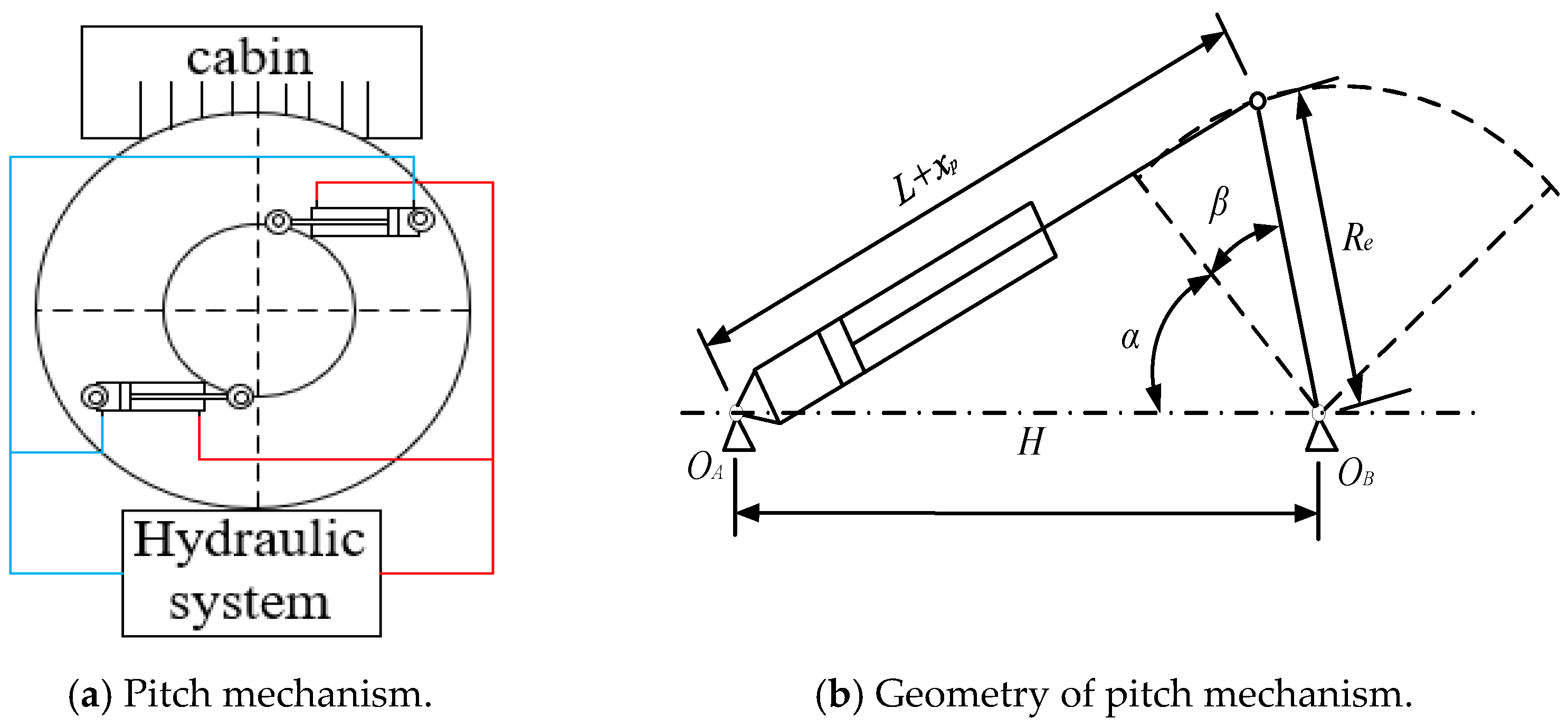
2. Pitch System Principles and Modeling

The electro-hydraulic servo pump-controlled variable pitch hydraulic system studied in this paper is illustrated in Figure 1. The system primarily consists of permanent magnet synchronous servomotors, bidirectional fixed-displacement hydraulic pumps, asymmetric hydraulic cylinders, accumulators, directional valves, check valves, and relief valves. By regulating the servomotor’s rotational speed, the hydraulic pump’s output flow is controlled, thereby adjusting the displacement of the hydraulic cylinder. The piston of the hydraulic cylinder is connected to the blade root via a pitch mechanism, which converts the piston’s linear motion into rotary motion to achieve blade pitch adjustment.
In the closed pump control system used, the hydraulic cylinder body is fixed on the hub through the hinge, the piston of the hydraulic cylinder is connected with the root of the blade through the hinge, the two hydraulic cylinders are mechanically synchronized, and the pitch action can be achieved by controlling the extension or retraction of the piston rod. The hydraulic cylinder extends in the direction of the propeller, and the pitch angle increases, while the hydraulic cylinder retracts in the direction of the counter-propeller, and the pitch angle decreases. The principle of the pitch system mechanism is shown in Figure 2a; by adjusting the flow rate of the output of the motor pump unit to control the hydraulic cylinder operating speed, the pitch speed is controlled.
In Figure 2b [11], α is the mounting angle, β is the pitch angle, OA denotes the articulation point between the hydraulic cylinder body and the hub, OB represents the rotational axis of the blade, and OC marks the articulation point connecting the hydraulic cylinder piston and the blade. The distance between OA and OC equals the sum of the minimum hydraulic cylinder length (L) when fully retracted and its displacement (xp). Meanwhile, the distance between OB and OC is a fixed value Re. The distance between OA and the blade’s rotational axis (OB) is defined as H, which corresponds to the mounting angle. The pitch angle is determined by the geometric relationship between these parameters.
Under the assumption of rigid-body behavior for the hydraulic cylinder assembly (including piston rod and linkages), the kinematic relationship between the actuator stroke and the blade pitch angle in the pitch adjustment mechanism (Figure 2) is governed by the following equation:
β = arccos R e 2 + H 2 ( L + x p ) 2 2 R e H α ,
From Equation (1), it can be concluded that the pitch angle depends solely on the hydraulic cylinder displacement once the pitch mechanism is rigidly installed. Therefore, precise control of the hydraulic cylinder displacement is the primary requirement for pitch angle regulation. Upon receiving the target pitch angle signal from the pitch system, this signal is converted into a hydraulic cylinder position command. The hydraulic cylinder position controller then compares the actual position with the target command and generates a servo motor speed signal. The servo motor drives the hydraulic pump to adjust the flow rate, enabling the hydraulic cylinder to reach the target position. Subsequently, the hydraulic cylinder actuates the pitch mechanism to achieve the desired pitch angle. This completes the pitch angle control process, as illustrated in Figure 3.
In response to the rapid load fluctuations imposed on offshore wind turbines, the interrelationships between servomotor speed, hydraulic cylinder displacement, and external load disturbances are systematically analyzed in the subsequent sections [12].
The load flow equation for a hydraulic pump can be expressed as follows:
Q p = D p ω m C i p ( P 1 P 2 ) C e p P 1 ,
In the formula, Qp—hydraulic pump output flow rate (L/min); wm—motor speed; DP—hydraulic pump displacement (mL/r); Cep—hydraulic pump external leakage coefficient (m3/(s-Pa)); Cip—hydraulic pump internal leakage coefficient (m3/(s-Pa)); P1—hydraulic pump high pressure chamber pressure (MPa); P2—hydraulic pump low pressure chamber pressure (MPa).
Considering the rodless chamber as the high-pressure side of the hydraulic cylinder, under conditions where both chambers possess equivalent effective volumes, the flow continuity equation governing the pressurized cavity can be expressed as follows:
Q p = A p 1 x ˙ p + C t c P 1 + V t 2 β e P ˙ 1 ,
A Rasch transformation of Equation (3) yields the following:
Q p = A p 1 x p s + C t c P 1 + V t 2 β e P 1 s ,
The load force balance equation for a hydraulic cylinder is as follows:
A p 1 P 1 A p 2 P 2 = M t x ¨ p + B p x ˙ p + K x p + F L ,
In the formula, Ap2—effective area of rod chamber (m2); Vt—effective volume of the hydraulic cylinder (m3); βe—modulus of the elasticity of oil (pa); Mt—equivalent mass of the piston-load assembly (kg); Ctc—hydraulic pump total leakage coefficient (m3/(s-Pa)); Bp—piston and load viscous damping coefficient (N/(m/s)); K—load spring stiffness (N/m); FL—external load interference force (N).
A Rasch transformation of Equation (5) yields the following:
A p 1 P l = M t x p s 2 + B p x p s + K x p + F L ,
Combined with Equations (2), (4) and (6), the following is obtained:
x P = D p ω m V t 2 β e A p 1 s + K c A p 1 F L V t M t 2 β e A p 1 s 3 + K c M t A p 1 + V t B p 2 β e A p 1 s 2 + A p 1 + K c B p A p 1 + V t K 2 β e A p 1 s + K c K A p 1
In the formula, Kc—total leakage factor for hydraulic pumps and cylinders (m3/(s·Pa)).
In Equation (7), K c B p A p 1 A p 1 , the influence of hydraulic cylinder and hydraulic pump leakage coefficient on hydraulic cylinder displacement can be ignored, and the elastic load influence is not received in the pitching process, so the load spring stiffness can be regarded as 0, and the collation is shown in Equation (8).
x P = D p A p 1 ω m K c A p 1 2 V t 2 β e K c s + 1 F L s V t M t 2 β e A p 1 2 s 2 + K c M t A p 1 2 + V t B p 2 β e A p 1 2 s + 1 ,
Therefore, the hydraulic intrinsic frequency of the pump control system (wh) can be obtained as follows:
ω h = 2 β e A p 1 2 V t M t ,
The hydraulic damping ratio ( ζ h ) is as follows:
ζ h = K c 2 A p 1 2 β e M t V t + B p 2 A p 1 V t 2 β e M t ,
Thus, the transfer function of the servo motor speed to the hydraulic cylinder displacement can be obtained as follows:
x P ω m = D p A p 1 s 1 ω h 2 s 2 + 2 ζ h ω h s + 1 ,
The transfer function of the external load disturbance force on the displacement of the hydraulic cylinder is as follows:
x p F L = K c A p 1 2 V t 2 β e K c s + 1 s 1 ω h 2 s 2 + 2 ζ h ω h s + 1 ,

3. Load Disturbance Compensation Model

Offshore wind turbines operate in environments characterized by highly dynamic wind speed and directional variations. Environmental factors such as waves, tides, and currents impose dynamic stresses on the turbine’s tower and foundation structures. These disturbances propagate through the system, ultimately generating significant load fluctuations within the pitch control mechanism.
Moreover, these load perturbations directly degrade the positional control accuracy of the pump-controlled pitch system. To address this, the real-time state monitoring of the disturbances is proposed to dynamically counteract hydraulic cylinder displacement fluctuations induced by such perturbations.
Using Equation (5), hydraulic cylinder load force balance equation can be obtained as follows:
F L = A p 1 P 1 A p 2 P 2 M t x ¨ p B p x ˙ p K x p ,
From Equation (13), the load force of the hydraulic cylinder can be observed in real time through the hydraulic cylinder displacement and system pressure, and its model is shown in Figure 4.
From the aforementioned load disturbance observation, relatively accurate observed load values can be obtained. Based on the control mechanism of the pump-controlled cylinder system, compensatory control is implemented for system variations caused by load disturbances. This approach effectively suppresses or even eliminates the impact of load disturbances on the rotational speed control of the system. Compensation control for load disturbance, based on the mathematical model of the pump control system, yields the load disturbance compensation control principle shown in Figure 5.
By the principle of structural invariance, F1 is taken as the observation and is set as a feed-forward compensator for G(s); then, the effect of F1 on the displacement of the hydraulic cylinder will be canceled out, compensating for the control of load disturbances as follows:
G ( s ) · K ( s ) = F ( s ) ,
where F(s) is the transfer function from the load disturbance Fl to the disturbance injection point (Ph), which can be expressed as follows:
F ( s ) = K e A 2 P 1 ( V t 2 β e K c s + 1 ) ,
K(s) is the transfer function from the perturbation compensation point ( ) to the perturbation injection point (Ph), which can be expressed as follows:
K ( s ) = D p A P 1 ,
The coupled Equations (14)–(16) give the mathematical model of the pump-controlled motor load disturbance compensation as follows:
G ( s ) = K e D P A P 1 ( V t 2 β e K c s + 1 )
Based on the load observation of the pump control cylinder system, combined with the load disturbance compensation mathematical model obtained from the above structural non-deformation principle, the hydraulic cylinder load disturbance compensation position control transfer function block diagram is shown in Figure 6. The introduction of fuzzy control techniques into the design of compensator G(s) utilizes the strong robustness of fuzzy controllers to overcome the shortcomings of linear controllers with poor immunity to interference to improve the control performance.

4. Experimental and Simulation Results

4.1. Simulation

The joint simulation models of AMEsim (2020.1) and MATLAB (R2021a) for hydraulic cylinder position PID control and load disturbance compensation control are constructed, respectively, as shown in Figure 7.
According to the pitch system design requirements for electrical and hydraulic component selection, selection is completed according to the sample information to set the simulation parameters of each component, as shown in Table 1 below, for some of the parameters of the simulation model used in this paper.
The simulation curve of the pitch angle 8 versus the position of the hydraulic cylinder when the servomotor is running at a fixed speed of 2700 r/min with the system open loop is shown in Figure 8. From the figure, the pitch system designed in this paper can realize the variation of pitch angle from −3.5 to 90°, and there is an obvious nonlinear correlation between the hydraulic cylinder displacement and the pitch angle.
A sinusoidal signal of 0.05 Hz was applied to the hydraulic cylinder. The simulation results for both PID and LDC control are presented in Figure 9. The curves indicate that the designed LDC control method demonstrated rapid tracking of the sinusoidal signal, without amplitude decay. Compared to that for PID control, the LDC achieved a 50.6% reduction in maximum tracking error. The displacement variance between the PID control and the target signal was 41.15, whereas the LDC control exhibited a variance of only 2.02. This represents a 95.1% improvement in positional accuracy (evaluated via displacement variance) for LDC over PID. These results confirm that the LDC control outperforms PID in tracking sinusoidal signals.
Setting the displacement step signal of the hydraulic cylinder from 100–700 mm, its simulation results for PID control and LDC control are shown in Figure 10. The time required to reach the steady state under PID control is 14.4 s, and the time required to reach the warm pond under LDC control is 13.8 s. A simulation performance comparison of LDC and PID control strategies is shown in Table 2.
The pitch change process can be divided into a power adjustment portion between 0 and 35° and a wind turbine protection adjustment portion between 35 and 90°. The former mainly relies on fine adjustment to change the windward area of the paddle blade to change the amount of wind energy utilization, to control the wind turbine to be able to output constant power, and to improve the quality of power generation; the latter occurs mainly when the wind speed reaches or exceeds the cut-out value, and the main purpose is to protect the wind turbine and to achieve protective stopping.
Figure 11 below shows the PID and LDC control pitch angle step response curve. As can be seen from the figure, LDC is slightly better than PID control in terms of steady state accuracy, but control accuracy can be stabilized within 0.05°; in terms of dynamic response, the LDC control system acceleration phase and constant speed operation phase are faster than those of the PID control, and the regulation time of LDC is reduced by 26.7% compared to that of PID, providing a faster transition to the steady state phase.
After 18 s of the step signal, a random disturbance force is applied to the system, the value of which is a random fluctuation, with an increased amplitude of 15 on top of 81.6 kN, and the following disturbance force is applied to the two hydraulic cylinders of the system at the same time in order to simulate random disturbance loads in actual operation and verify the anti-disturbance capability of the LDC control. The random disturbance force is shown in Figure 12, along with its simulation in PID control and LDC control. The results are shown in Figure 13.
From the control curves of hydraulic cylinder displacement and pitch angle of PID and LDC after applying random disturbance force, it can be seen from the figure that after suddenly applying disturbance force, the hydraulic cylinder displacement and pitch angle of PID control and LDC control exhibit the same degree of displacement drop, but the hydraulic cylinder displacement and pitch angle of LDC control can overcome the disturbance to return to the target position faster, with a stronger response compared to that of the PID control, and it also displays anti-interference ability.

4.2. Experimentation

The electro-hydraulic servo pump-controlled independent variable pitch experimental system is shown in Figure 14. The electrical system includes programmable controllers, servo drives, servo motors, sensors, and other components. The servo motor drives the hydraulic pump coaxially, and the hydraulic cylinder position control is realized by adjusting the flow output of the hydraulic pump; the use of the oil charge accumulator with the liquid-controlled check valve compensates for the asymmetric flow and the internal and external leakage flow of the system; the use of the paddle accumulator enables the system to complete the paddle action and adjusts the paddle pitch angular speed when paddling via the unidirectional throttling speed control valve. When the system is overloaded, the system will be unloaded via the relief valve. The controller can monitor and collect the pressure, position, temperature, and other state parameters in the system in real time through the sensor, and through the designed position control strategy, based on load perturbation compensation, according to the target displacement and the actual displacement after the comparison of the output servo motor speed signals, the use of EtherCAT communication will provide the desired speed output to the servo drive, followed by the drive through the encoder cable to the servo motor speed control, controlling the hydraulic pump output flow to realize the position of the hydraulic cylinder.
The maximum output flow rate of the motor pump set used in this experiment is 118 L/min, the maximum pressure is 35 MPa, the maximum stroke of the hydraulic cylinder used is 400 mm, and the other key components used are shown in Table 3.
Setting the displacement step signal of the hydraulic cylinder from 100–700 mm, its simulation results in PID control and LDC control are shown in Figure 15. The time required to reach the steady state under PID control is 18.2 s, and the time required to reach the warm pond under LDC control is 17.4 s.
The position control accuracy and tracking ability of the designed load disturbance compensation controller are mainly tested via continuous step and sinusoidal response tests, and the test results are shown in Figure 16 and Figure 17.
From Figure 16, the average time required to reach a steady state for each segment is 4.97 s for PID control and 4.38 s for LDC control; it can be seen that the designed LDC control method is able to realize fast and overshoot-free control of continuous step commands for hydraulic cylinders, which meets the demand of continuous pitch control for variable pitch system.
A sinusoidal signal with an amplitude of 50 mm and a gradually increasing frequency from 0.05 to 0.08 Hz was applied; the results are shown in Figure 17. The displacement sensor used has a resolution of 50 μm and a sampling frequency of 40 Hz. The designed LDC control method is able to track the sinusoidal signal quickly and without amplitude decay. In addition, compared with the PID control curve, the maximum tracking error of the PID control is 12.66 mm, the maximum tracking error of the LDC control is 2.42 mm, and the displacement variance between the PID and the target signal is 43.18. The displacement variance between the designed LDC and the target signal is 2.98. Evaluated in terms of the displacement variance, the positional accuracy of the designed LDC is 93.1% higher than that of the PID. It can be seen that the designed LDC control method is able to follow the sinusoidal signal better than is the PID, which verifies the correctness of the simulation results. An experimental performance comparison of the LDC and PID control strategies is shown in Table 4.

5. Conclusions

In this paper, to meet the demand for the high-precision control of the pitch control system of offshore wind turbines under complex environmental loads, a nonlinear mapping model comparing hydraulic cylinder displacement and pitch angle is established, and an electromechanical–hydraulic coupled state–space equation containing the electromagnetic characteristics of the servomotor, the continuity of the flow in the hydraulic system, and the dynamics of the load is constructed. A load prediction method is proposed, and a position control strategy based on the compensation of the load disturbance is designed, with higher displacement tracking accuracy and stronger anti-interference ability than the traditional PID control, and its superiority is revealed through simulation and experimental verification.
The load observation model proposed in the paper, grounded in physics-based equations, is theoretically scalable to turbines of varying sizes. However, under extreme operating conditions, factors such as variations in system leakage coefficients and hydraulic fluid viscosity may necessitate a reevaluation of key parameters within the model. The load disturbance compensation strategy proposed in this study provides an effective solution for high-precision anti-disturbance control of an offshore wind turbine pitch system, which can be applied not only to the offshore wind turbine pitch system, but also to the same type of strong-disturbance electro-hydraulic control system. However, the practical application still needs to overcome the challenges of the simplicity of the modeling assumptions, the reliability of the sensors, and the adaptability to extreme environments. Future work can explore the adaptability improvement of multiple types of turbines and further enhance the robustness of the system under extreme environments such as typhoons and extreme cold by integrating weather prediction, temperature adaptive algorithms, and digital twin technology. In addition, by combining edge computing and fault tolerance mechanisms, it is expected to realize autonomous and highly reliable operation under complex sea conditions, providing theoretical support for the intelligent development of renewable energy equipment.

Author Contributions

Conceptualization, X.W. and S.L.; methodology, S.L. and G.C.; experiment, J.C. and C.A.; software, X.W. and J.C.; investigation, X.K.; writing—original draft preparation, X.W.; writing—review and editing, J.C.; analysis, S.L.; project administration, C.A.; funding acquisition, C.A. and X.K. All authors have read and agreed to the published version of the manuscript.

Funding

This research was funded by the National Natural Science Foundation of China (U22A20178), the Basic Research Funds for the Universities of Xinjiang (XJEDU2024P087 and XJEDU2023P138), the Natural Science Foundation of the Xinjiang Uygur Autonomous Region (2022D01A244), the Guizhou Provincial Basic Research Program (Natural Science) ([2020]1Z054), and the Hebei Provincial Major Special Science and Technology Project (23281901Z).

Institutional Review Board Statement

Not applicable.

Informed Consent Statement

Not applicable.

Data Availability Statement

The original contributions presented in the study are included in the article; further inquiries can be directed to the corresponding author.

Conflicts of Interest

Author Xuewei Wang was employed by the company Sichuan Chuanrun Intelligent Fluid Technology Co., Ltd. The remaining authors declare that the research was conducted in the absence of any commercial or financial relationships that could be construed as a potential conflict of interest.

Abbreviation

The following abbreviation is used in this manuscript:
LDCload disturbance compensation

References

  1. Guo, Y.; Wang, H.; Lian, J. Review of integrated installation technologies for offshore wind turbines: Current progress and future development trends. Energy Convers. Manag. 2022, 255, 115319. [Google Scholar] [CrossRef]
  2. Narayanan, V.L.; Dhaked, D.K.; Sitharthan, R. Improved machine learning-based pitch controller for rated power generation in large-scale wind turbine. Renew. Energy Focus 2024, 50, 100603. [Google Scholar] [CrossRef]
  3. Fitzgerald, B.; Sarkar, S. Observer based pitch control for load mitigation and power regulation of floating offshore wind turbines. J. Phys. Conf. Ser. 2024, 2647, 032003. [Google Scholar] [CrossRef]
  4. Deng, W.; Gao, Y.; Chen, H.; Sun, Y.; Zhang, L. Analysis of Various Aggregation Boost Topologies for DC Offshore Wind Power. In Proceedings of the 2024 6th Asia Energy and Electrical Engineering Symposium (AEEES), Chengdu, China, 28–31 March 2024; pp. 1114–1120. [Google Scholar]
  5. Su, X.; Wang, X.; Xu, W.; Yuan, L.; Xiong, C.; Chen, J. Offshore wind power: Progress of the edge tool, which can promote sustainable energy development. Sustainability 2024, 16, 7810. [Google Scholar] [CrossRef]
  6. Li, S.; Du, M.; Li, Y.; He, J.; Ma, F.; Chen, Q. Independent Pitch Controller based on Fuzzy Adaptive Tuning PI for Load Mitigation of Large Land Wind Turbine. J. Phys. Conf. Ser. 2023, 2655, 012007. [Google Scholar] [CrossRef]
  7. Fayazi, A.; Ghayoumi Zadeh, H.; Ahmadian, H.; Ghane, M.; Seryasat, O.R. Pitch Actuator Fault-Tolerant Control of Wind Turbines via an L 1 Adaptive Sliding Mode Control (SMC) Scheme. Energies 2024, 17, 3963. [Google Scholar] [CrossRef]
  8. Pan, L.; Xiong, Y.; Zhu, Z.; Wang, L. Research on variable pitch control strategy of direct-driven offshore wind turbine using KELM wind speed soft sensor. Renew. Energy 2022, 184, 1002–1017. [Google Scholar] [CrossRef]
  9. Wang, S.; Wang, B.; Shen, W. Research on H∞ Robust Control Strategy of Wind Turbine Hydraulic Variable Pitch System. IOP Conf. Ser. Earth Environ. Sci. 2021, 696, 012053. [Google Scholar] [CrossRef]
  10. Ai, S.; Su, J.; Meng, W.; Yan, Y. Integrated control of blade pitch and generator speed for floating wind turbines. Ocean. Eng. 2024, 300, 117080. [Google Scholar] [CrossRef]
  11. Zhang, T.; Yu, B.; Wang, X.; Liu, Y.; Chen, G.; Liu, K.; Ai, C.; Wang, L. Adaptive Robust Control for Pump-Controlled Pitch Systems Facing Wind Speed and System Parameter Variability. Appl. Sci. 2024, 14, 10218. [Google Scholar] [CrossRef]
  12. Zhang, T.; Yu, H.; Yu, B.; Ai, C.; Lou, X.; Xiang, P.; Li, R.; Li, J. Electro-Hydraulic Servo-Pumped Active Disturbance Rejection Control in Wind Turbines for Enhanced Safety and Accuracy. Processes 2024, 12, 908. [Google Scholar] [CrossRef]
  13. Wang, H.; Zhang, Y.; An, Z.; Liu, R. An energy-efficient adaptive speed-regulating method for pump-controlled motor hydrostatic drive powertrains. Processes 2023, 12, 25. [Google Scholar] [CrossRef]
  14. Zhang, T.; Yan, G.; Liu, X.; Yao, C.; Ai, C. Nonlinear flow modeling of electro hydrostatic pump unit based on Gauss Newton iterative method for high performance control. Sci. Rep. 2024, 14, 21750. [Google Scholar] [CrossRef]
  15. Zhao, L.; Gong, Y.; Li, Z.; Wang, J.; Xue, L.; Xue, Y. Rapid Estimation Model for Wake Disturbances in Offshore Floating Wind Turbines. J. Mar. Sci. Eng. 2024, 12, 647. [Google Scholar] [CrossRef]
  16. Yang, W.; Han, Y.; Ma, R.; Hou, M.; Yang, G. A composite super-twisting sliding mode approach for platform motion suppression and power regulation of floating offshore wind turbine. J. Mar. Sci. Eng. 2023, 11, 2318. [Google Scholar] [CrossRef]
  17. Cui, L.; Aleem, M.; Shivashankar; Bhattacharya, S. Soil–structure interactions for the stability of offshore wind foundations under varying weather conditions. J. Mar. Sci. Eng. 2023, 11, 1222. [Google Scholar] [CrossRef]
  18. Henry, A.; Pusch, M.; Pao, L. Investigation of H∞-Tuned Individual Pitch Control for Wind Turbines. Wind Energy 2024, 27, 1074–1094. [Google Scholar] [CrossRef]
  19. Hlaing, N.; Morato, P.G.; Santos, F.d.N.; Weijtjens, W.; Devriendt, C.; Rigo, P. Farm-wide virtual load monitoring for offshore wind structures via Bayesian neural networks. Struct. Health Monit. 2024, 23, 1641–1663. [Google Scholar] [CrossRef]
  20. Kim, D.; Ryu, G.; Moon, C.; Kim, B. Accuracy of a short-term wind power forecasting model based on deep learning using LiDAR-SCADA integration: A case study of the 400-MW Anholt offshore wind farm. Appl. Energy 2024, 373, 123882. [Google Scholar] [CrossRef]
  21. Bai, D.; Wang, B.; Li, Y.; Wang, W. Study on load reduction and vibration control strategies for semi-submersible offshore wind turbines. Sci. Rep. 2025, 15, 1148. [Google Scholar] [CrossRef]
  22. Tohamy, Y.E.; Giger, U.; Marten, D.; Schulte, H. Multi-Rotor Wind Turbine Control: Strategies for Pitch Replacement and Mechanical Load Mitigation. J. Phys. Conf. Ser. 2024, 2767, 032015. [Google Scholar] [CrossRef]
  23. Zhang, S.; Wang, Y.; Liu, Y.; Wang, X.; Bai, W.; Cao, T. Improved control strategy and designed control parameters of pitch system for wind turbine considering blade load reduction. Renew. Energy 2024, 232, 121050. [Google Scholar] [CrossRef]
  24. Kipchirchir, E.; Söffker, D. IPC-based robust disturbance accommodating control for load mitigation and speed regulation of wind turbines. Wind Energy 2024, 27, 382–402. [Google Scholar] [CrossRef]
  25. Xiao, Y.; Wang, X.; Sun, X.; Zhong, X.; Peng, C.; Dai, L.; Maeda, T.; Cai, C.; Li, Q.a. Load reduction and mechanism analysis of cyclic pitch regulation on wind turbine blades under yaw conditions. Ocean. Eng. 2025, 321, 120361. [Google Scholar] [CrossRef]
  26. Yao, Y.; Huang, S.; Wang, K.; Zhao, M.; Liu, H. Study on the aeroelastic response of wind turbine blades with pitch system failure and strategies for typhoon resistance. Ocean. Eng. 2025, 324, 120734. [Google Scholar] [CrossRef]
  27. Hu, X.; Wang, Q.; Jiang, T.; Zhan, S. Adaptive Fault-tolerant Pitch Control of Wind Turbines. In Proceedings of the 35th Chinese Control and Decision Conference (CCDC), Yichang, China, 20–22 May 2023; IEEE: Piscataway, NJ, USA, 2023; pp. 5144–5149. [Google Scholar]
  28. Hu, H.; Peng, L.; Li, X.; Chen, Y.; Yan, J.; Guo, P.; Cheng, B. A New L1 Neural Network Adaptive Wind Turbine Pitch Control Strategy. J. Circuits Syst. Comput. 2025, 34, 2550020. [Google Scholar] [CrossRef]
  29. Liu, Y.; Wang, Y.; Wang, X. Independent Pitch Adaptive Control of Large Wind Turbines Using State Feedback and Disturbance Accommodating Control. Energies 2024, 17, 4619. [Google Scholar] [CrossRef]
Figure 1. Schematic of electro-hydraulic servo pump-controlled independent variable pitch system.
Applsci 15 06468 g001
Figure 2. Schematic and principle of variable pitch mechanism.
Applsci 15 06468 g002
Figure 3. Electro-hydraulic servo pump-controlled independent pitch control flow chart.
Applsci 15 06468 g003
Figure 4. Load prediction model diagram.
Applsci 15 06468 g004
Figure 5. Schematic diagram of load disturbance compensation transfer function.
Applsci 15 06468 g005
Figure 6. Hydraulic cylinder load disturbance compensation position control transfer function control flow chart.
Applsci 15 06468 g006
Figure 7. Joint simulation model of AMEsim and MATLAB.
Applsci 15 06468 g007
Figure 8. Hydraulic cylinder displacement vs. pitch angle curve.
Applsci 15 06468 g008
Figure 9. Simulation results of sinusoidal signal.
Applsci 15 06468 g009
Figure 10. Simulation results of the step signal.
Applsci 15 06468 g010
Figure 11. Simulation results of the angular step.
Applsci 15 06468 g011
Figure 12. Random disturbing forces.
Applsci 15 06468 g012
Figure 13. Hydraulic cylinder displacement under random disturbance force.
Applsci 15 06468 g013
Figure 14. Electro-hydraulic servo pump-controlled independent variable pitch experimental system.
Applsci 15 06468 g014
Figure 15. Step experiment results.
Applsci 15 06468 g015
Figure 16. Continuous step experiment results.
Applsci 15 06468 g016
Figure 17. Sinusoidal experiment result.
Applsci 15 06468 g017
Table 1. Partial parameters of the main components of the simulation model.
Serial NumberParameter NameValue
1Max system pressure35 MPa
2Rated system pressure26 MPa
3Cylinder structure parameters200-140-800 mm
4Hydraulic pump displacement80 mL/r
5Rated motor speed1800 r/min
6Max motor speed2700 r/min
7Servo motor moment of inertia6.073·10−2 kg·m2
8Hydraulic pump moment of inertia6.05·10−2 kg·m2
Table 2. Simulation performance comparison of LDC and PID control strategies.
Instruction SignalParameterPID ControlLDC Control
Step signal (100–700 mm)Settling time14.4 s13.8 s
Sinusoidal signal (50 mm, 0.05 HZ)Maximum tracking error12.66 mm2.42 mm
Displacement variance41.52.02
Table 3. Key experimental components and their manufacturers.
Component NameModelManufacturer
AccumulatorNXQ-AB-25Liming (Zhoushan, China)
Check ValveS20P21BHuade (Beijing, China)
Relief ValveRDFALWNSUN (Houston, TX, USA)
Reversing ValveDFEBMCN-224SUN
Throttle ValveNFDDLGNSUN
Temperature SensorPH4000Zhuhong (Wuxi, China)
Pressure SensorsPH3600Zhuhong
Displacement SensorSSI Displacement SensorsXiju (Nanjing, China)
Table 4. Experimental performance comparison of LDC and PID control strategies.
Instruction SignalParameterPID ControlLDC Control
Step signal (800 mm)Settling time18.2 s17.4 s
Continuous step signal (100–800 mm)Average settling time4.97 s4.38 s
Sinusoidal signal (50 mm, 0.05–0.08 HZ)Maximum tracking error12.66 mm2.42 mm
Displacement variance43.182.98
Disclaimer/Publisher’s Note: The statements, opinions and data contained in all publications are solely those of the individual author(s) and contributor(s) and not of MDPI and/or the editor(s). MDPI and/or the editor(s) disclaim responsibility for any injury to people or property resulting from any ideas, methods, instructions or products referred to in the content.

