Abstract
This paper proposes a method for array design and optimal transmitting coil selection of underwater wireless power transfer systems. This method is divided into three steps. Firstly, by analyzing the influence of different ratio side lengths of the transmitting coil and receiving coil on mutual inductance, the optimal ratio side length coil is selected. Secondly, by analyzing the relative size of the reflection impedance of the power supply coil and its surrounding coils, the optimal coil activation criterion is derived. Finally, by estimating the position of the receiving coil without communication, the switching of the power supply coil is realized. According to the proposed method, it was verified on the experimental platform. Under a rated power of 300 W with a load resistance of 20 Ω, the system maintains efficiency ≥ 80% even under horizontal offsets up to 150 mm (75% of the transmitting coil side length) and two-dimensional offsets up to 200 mm (100% of the transmitting coil side length).
1. Introduction
Underwater electromechanical equipment have demonstrated significant application value in the domains of marine exploration, ocean development, and hydrological monitoring. As the principal power source for underwater electromechanical systems, the mode of electric energy transmission has emerged as a critical challenge. Traditional underwater power transmission predominantly employs the wet mating technique, wherein power is conveyed via metal conductors. However, the underwater environment can induce corrosion and aging in these metal wires, thereby reducing their operational lifespan. Moreover, this wet mating interface presents several drawbacks, including complicated docking procedures, elevated costs, and a limited service life.
The advent of wireless power transfer (WPT) technology presents a viable solution to address the limitations inherent in conventional energy transmission methodologies. Nevertheless, operational challenges arise when implementing this technology in aquatic environments. Due to the dynamic hydrodynamic forces exerted by water currents, submerged electromechanical systems inherently lack the positional stability characteristic of terrestrial installations. This mobility-induced instability results in misalignment of the coupling interface during subaqueous charging operations. Such spatial displacement between the receiver and transmitter coils directly compromises the magnetic coupling efficiency, leading to progressive deterioration of system performance metrics. Specifically, the coupling coefficient diminishes exponentially as angular deviation increases, consequently causing substantial degradation in power transfer efficiency accompanied by marked elevation in resistive power dissipation.
To augment the anti-offset performance and optimize the power transfer efficiency of Underwater Wireless Power Transfer (UWPT) systems, researchers have conducted extensive investigations into three principal technical strategies. The predominant approaches currently under exploration include: (1) a capture-and-fixation methodology for positional stabilization, (2) advanced control optimization techniques for dynamic regulation, and (3) coupling structure refinement through electromagnetic field modulation.
Based on distinct capture mechanisms, underwater electromechanical equipment fixation systems can be categorized into three primary configurations: capture-type [1], platform-type [2], and containment-type [3]. These methodologies employ peripheral mechanical systems to achieve stable capture and secure positioning of submerged equipment, effectively mitigating hydrodynamic disturbances and enhancing system resistance to positional deviations. The implementation of such containment strategies specifically addresses the critical challenge of positional instability in underwater wireless power transfer systems. Once the electromechanical components are securely stabilized through these mechanical interfaces, the operational environment achieves requisite stability for reliable energy transmission, thereby facilitating numerous successful engineering applications. Notwithstanding these advantages, current implementations require the development of sophisticated mechanical architectures and present technical challenges associated with precision docking operations.
Based on distinct control architectures, the control optimization methodology is categorized into transmitter-side regulation and receiver-side regulation. This approach enhances the system offset suppression capability through dynamic modulation of critical operational parameters including excitation frequency, voltage levels, and current characteristics. The transmitter-side control strategy is primarily implemented in inverter topologies and compensation networks, achieving enhanced offset rejection through coordinated implementation of frequency conversion phase shifting, switched inductive elements, and adaptive capacitive elements [4,5]. To address the challenge posed by spatial displacement between transmitting (TX) and receiving (RX) coils induced by hydrodynamic disturbances, an adaptive power regulation strategy utilizing primary-side current feedback has been developed as detailed in reference [6]. The proposed approach dynamically adjusts the duty cycle of switch tube triggering pulses in the inverter circuit through real-time monitoring of transmission-side current parameters. This control mechanism significantly enhances the system’s resilience to positional deviations while maintaining operational stability. Experimental validation demonstrates that the optimized control algorithm sustains peak power transfer efficiency across varying inter-coil gaps, confirming its effectiveness in mitigating fluid-induced misalignment effects. Aiming at the problem that the offset of the coupling mechanism affects its mutual inductance. In [7], a novel solenoid coil is proposed, thereby enhancing the average mutual inductance of the WPT system.
The experimental results demonstrate a significant reduction in mutual inductance fluctuations within the system compared to conventional methods. The receiver control is mainly used in the rectifier circuit and DC chopper circuit, and the anti-offset performance of the system is improved by means of frequency conversion phase shift and duty cycle control [8,9]. Aiming at the problem of the coupling coefficient change. In [10], a series compensation topology and control strategy with bilateral power control is proposed. The efficiency of the system is improved by controlling the switching tube of the rectifier circuit through voltage, current, and other parameters. In [11], a novel control strategy is proposed to enhance the dynamic response of UWPT systems. The study employs a switched-capacitor DC-DC converter topology integrated with a nonlinear one-cycle control method. This innovative approach effectively compensates for power fluctuations caused by lateral misalignment between the transmitting and receiving coils.
In summary, the control optimization method can also improve the anti-offset performance of the underwater wireless power transfer system. However, this method also has some drawbacks. It is limited by the difficulty of communication in the underwater environment. The transmitter and the receiver cannot establish information interaction. The control strategy is mostly limited to unilateral control, and the method does not improve the anti-offset performance of the system. The controllable offset range is small, so the current method plays a more auxiliary role.
The coupling mechanism optimization method is the main method to improve the anti-offset performance of the underwater wireless power transfer system. The optimization method is mainly divided into two types: coil structure optimization [12] and coil array optimization [13]. The optimization of the coil structure is mainly used for single-to-single coil power supply. Through the structural design of the coupling mechanism, the docking between the transmitting end and the receiving end is realized, and the coupling mechanism can be used to form interlockment to improve the anti-offset performance of the system. However, the structural design of the coupling mechanism using this method is more complex and the external influence factors increase. At present, there are few studies on coil array optimization, mainly using multiple transmitting coils to expand the charging area to improve the anti-offset range of the system. In order to improve the transmission performance of the system and reduce the power loss, it is necessary to design the coil switching control strategy and select the optimal power supply coil.
Coil structure optimization refers to the optimized design of the transmitter coil and the receiver coil, so that it has stronger anti-offset performance [13,14,15,16,17]. In [18], a conical electromagnetic coupling mechanism with good offset tolerance and transmission efficiency in an underwater environment was proposed. A conical electromagnetic coupling mechanism with a gap of 5 mm was designed and tested in salt water. The results show that the system can transmit energy at 300 W power, and the maximum efficiency is 88%. The system is easy to connect and has high stability. In [15], a new type of magnetic coupling structure was designed. The receiving end adopts the embedded propeller mode, and the transmitting side adopts the vertical arrangement mode to form the annular magnetic field. This coil structure can optimize the magnetic field distribution and significantly reduce the interference to the internal equipment of the Autonomous Underwater Vehicle (AUV). At the same time, it has a strong anti-rotation offset performance. In [19], a new type of high-tolerance pendulum coupling mechanism suitable for underwater wireless power transfer of an AUV was proposed. The coupling mechanism not only has a compact structure, light weight, and strong anti-offset performance, but also has high transmission efficiency. The experimental results show that the system output is stable in the range of rotation and axial offset [−30 mm, 30 mm], and the efficiency is always above 95%, and the efficiency fluctuation is less than 1%.
Coil array optimization refers to the use of the basic coil structure to build a multi-transmit coil array, and the anti-offset performance of the system is improved by optimizing the array shape and arrangement [20,21,22]. In [23], a hexagonal coil array with dynamic switching control was proposed, which enhances spatial coverage and efficiency in multi-receiver WPT systems by adaptively activating sub-arrays based on receiver positions. In [24], a scheme for optimizing the coil layout of the underwater wireless power transfer system was proposed. The transmitting end adopts the arrangement of double-layer coils up and down to form a transmitting coil array. The receiving end consists of two coils to form a coil array, so as to ensure that the underwater equipment can effectively carry out wireless power transfer at any position in the transmitting array area, with more than 74% transmission efficiency. In [25], a kilowatt-level WPT system for an AUV was designed. The transmitter of the system adopts a three-coil structure, which can effectively deal with the offset problem of the coupling mechanism, with high position freedom and high transmission efficiency. The experimental results show that the system can transmit wireless power in a seawater environment with a high degree of freedom. The transmission power can reach 3 kW and the efficiency is 77% to 80%.
In summary, the optimization of the coupling mechanism can effectively solve the problem of coil offset caused by water flow disturbance. Among them, the optimization of the coil structure will complicate the coil body structure and manufacturing process, and have higher requirements for application scenarios and equipment; the optimization method of the coil array is to expand the number of coils at the transmitting end and expand the charging range. The requirements for the coil structure at the receiving end are not high, the application range is wider, and the anti-offset effect is better. Therefore, this paper will use the coil array optimization method to improve the anti-offset performance of the system.
Aiming at the problem that the water flow disturbance causes the coil offset of the receiving end to affect the transmission performance in the complex marine environment, this paper mainly studies a new array underwater wireless power transfer system. The coupling mechanism of the system adopts an array design, which expands the charging range and improves the anti-offset ability of the system.
The main contributions of this paper are summarized as follows:
- (1)
- The proposed methodology quantitatively identifies the optimal dimensional proportion between transmitting and receiving coils by systematically investigating the impact of their size ratio on the mutual inductance variation under offset conditions, thereby achieving the optimized configuration for array-coupling mechanisms.
- (2)
- The spatial position of the receiving coil is precisely identified through the comparative analysis of reflection impedance characteristics between the target power transmission coil and its adjacent coils, thereby facilitating the optimized selection and activation of the most suitable power supply coil configuration.
2. UWPT System for AUVs
Aiming at the problem that the coupling mechanism offset caused by water flow disturbance affects the transmission efficiency in a complex marine environment, an array underwater wireless power transfer system suitable for AUVs was designed in this chapter. The coupling mechanism of the system adopts an array design, which expands the charging range and improves the anti-offset ability of the system. The working diagram of the UWPT system is shown in Figure 1.
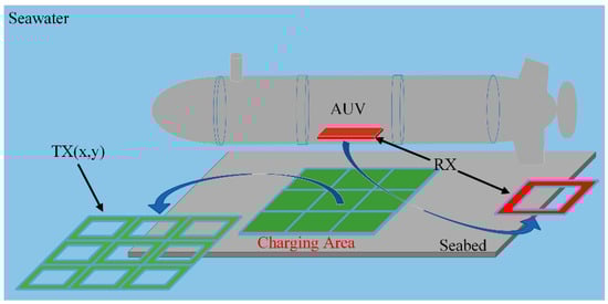
Figure 1.
Image of proposed WPT system for AUVs.
The array UWPT system adopts the S-S compensation network topology, and its simplified circuit diagram is shown in Figure 2. The system includes a high frequency inverter and rectifier, compensation capacitors Ca and Cb, switch S11 to S33, transmitting array coil TX(1, 1) to TX(3, 3), and receiving coil RX. In the process of power transmission, the optimal power supply coil switch is closed by determining the position of the receiver, so that the power supply coil is connected to the compensation capacitor and the inverter; the other array coils are in the open circuit state.
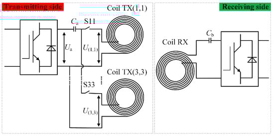
Figure 2.
Simple circuit configuration of WPT system.
The S-S compensation topology was chosen for its simplicity and array compatibility: it provides stable impedance at 85 kHz, reducing complexity in 3 × 3 array switching. Compared to LCC-S (extra inductors) or S-SP (higher losses), S-S maintains efficiency better under misalignment, which is ideal for AUV dynamic offsets.
3. Coupling Mechanism Design and Array Switching Control Strategy
3.1. Coupling Mechanism Design
3.1.1. The Basic Unit Shape Design of Transmitting Array Coil Group
The planar coil structure can generally be divided into a circular spiral structure and square spiral structure, and the magnetic field distribution of the two is shown in Figure 3. It can be seen from the diagram that the magnetic field intensity of the circular coil is close to that of the square coil, but the magnetic field distribution of the square coil is more uniform.
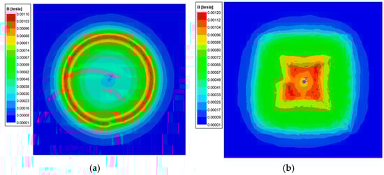
Figure 3.
Planar coil structure. (a) Circular spiral structure coil. (b) Square spiral structure coil.
The two structures are extended into an array form, as shown in Figure 4. It can be seen from the diagram that there is a large gap between the circular coil arrays, and the splicing between the coils is poor; on the contrary, the square coil array can be closely arranged, the coil gap is small, and it has stronger splicing. In summary, this paper selects the square coil as the basic unit shape of the transmitting array coil group. According to the charging area and the size of the underwater electromechanical equipment, the side length of the transmitting coil L1 is selected as 200 mm.
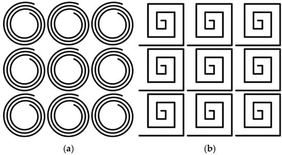
Figure 4.
Planar coil array. (a) Circular coil array. (b) Square coil array.
3.1.2. Layout Design of Transmitting Array
The arrangement of the transmitting array mainly has two kinds of interval arrangement and close arrangement. The interval arrangement means that there is a certain gap between the transmitting array coils, which is mainly suitable for the simultaneous power supply of multiple transmitting coils, which can reduce the coupling degree between the transmitting coils. Tight arrangement means that the transmitting array coils are densely arranged, and there is no gap between the coils, which is mainly suitable for single transmitting coil power supply. While this paper employs a one-to-one single transmitting coil power supply strategy (avoiding simultaneous multi-coil activation), electromagnetic coupling between adjacent transmitting coils (denoted MTX) still exists. This coupling is explicitly considered in the subsequent analysis and does not compromise the single-coil power supply logic, as unpowered coils remain open-circuited. So, the arrangement of the transmitting array coils in this paper adopts a close arrangement. The transmitting array coil group is composed of nine transmitting coils. According to the position of each transmitting coil, the transmitting array coil is labeled as TX(x, y), where x and y represent the horizontal and vertical coordinates of the transmitting array coil, and the value range is [1,3].
The transmitting array is configured as a 3 × 3 grid (9 coils) for the following reasons: (1) AUV size compatibility: With each coil side length of 200 mm, the total array size (600 mm × 600 mm) matches the typical horizontal offset range (±300 mm) of AUVs during docking. (2) Control complexity balance: A 3 × 3 array avoids the limited coverage of smaller arrays (e.g., 2 × 2) and the increased inter-coil coupling of larger arrays (e.g., 4 × 4). (3) Scalability: The 3 × 3 structure acts as a modular unit, enabling easy expansion to larger arrays (e.g., 5 × 5) while preserving the proposed switching strategy. The transmitting array coil group is shown in Figure 5.
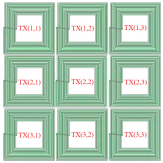
Figure 5.
The transmitting array coil group.
3.1.3. Receiving Coil Design
The receiving end uses the coupling between the receiving coil and the transmitting coil to obtain electrical energy. The selection of the receiving coil size has a great influence on the transmission performance of the system, and the size ratio of the transmitting coil to the receiving coil will affect the anti-offset performance of the system. In the horizontal direction, the coupling mechanism offset mainly has three kinds of transverse displacement, longitudinal displacement, and rotational displacement. The horizontal offset of the coupling mechanism is shown in Figure 6. Among them, α is the rotation offset angle, dx and dy are the transverse displacement distance and the longitudinal displacement distance respectively, and h is the height between the transmitting coil and the receiving coil.
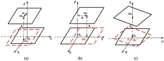
Figure 6.
Coupling mechanism offset in the horizontal direction. (a) Transverse displacement. (b) Longitudinal displacement. (c) Rotational displacement.
The Maxwell software used to simulate the underwater environment, and the influence of the size change between the transmitting coil and the receiving coil on the system was studied. Under the condition of different coil size ratios, when the coupling mechanism is transverse and has rotational displacement, the mutual inductance change curve between the transmitting coil and the receiving coil is shown in Figure 7.
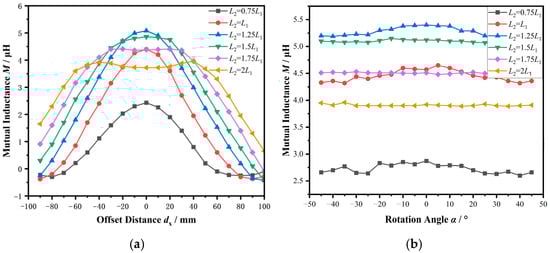
Figure 7.
The variation curve of mutual inductance with coil offset. (a) Transverse displacement. (b) Rotational displacement.
It should be noted that seawater, as a conductive and dielectric medium, significantly affects the UWPT system’s electromagnetic characteristics. Seawater’s high conductivity (σ ≈ 4 S/m) induces eddy currents in the surrounding medium during coil operation, increasing the effective series resistance of the transmitting and receiving coils and causing additional power loss. Meanwhile, its high relative permittivity (εr ≈ 80) redistributes the electromagnetic field, slightly modifying the self-inductance of individual coils and the mutual inductance between coils. To ensure accuracy, these parameters (σ = 4 S/m, εr = 80) were explicitly set in the Maxwell simulation environment during the mutual inductance analysis (Figure 7).
It can be seen from Figure 7a that as the size ratio of the side length L1 of the transmitting coil to the side length L2 of the receiving coil increases, the maximum mutual inductance between the transmitting coil and the receiving coil increases first and then decreases, and reaches the maximum when L2 = 1.25L1. However, while L2 = 1.25L1 yields the highest mutual inductance, its anti-offset performance is not optimal. Specifically, the anti-offset range of the coil (i.e., the range over which mutual inductance remains relatively stable under misalignment) continues to expand as the size ratio L2/L1 increases beyond 1.25. This is because larger L2/L1 ratios result in more gradual mutual inductance variations during offset, enhancing the system’s tolerance to misalignment. The same trend applies to longitudinal displacement, consistent with the transverse displacement analysis. As shown in Figure 7b, although the maximum mutual inductance still occurs at L2 = 1.25L1, further increasing L2 leads to a broader anti-offset range where mutual inductance fluctuations are mitigated.
To quantify “anti-offset range,” we define it as the maximum displacement where mutual inductance M remains ≥80% of its aligned peak. For L2 = 1.25L1, M peaks at 5 μH, but drops to 80% (4 μH) at dx = 30 mm. For L2 = 1.75L1, M peaks at 4.4 μH, but retains 80% (3.5 μH) up to dx = 50 mm, almost doubling the anti-offset range. This trade-off is critical for AUVs, prioritizing stable power transfer over large offsets in turbulent waters.
Given the trade-off between mutual inductance magnitude and anti-offset performance—where larger L2/L1 ratios reduce peak mutual inductance but significantly improve misalignment tolerance—the final receiving coil side length is determined as L2 = 1.75L1 = 350 mm. This selection balances both mutual inductance and anti-offset capability to ensure robust power transfer under dynamic underwater conditions. The system coupling mechanism model is illustrated in Figure 8.
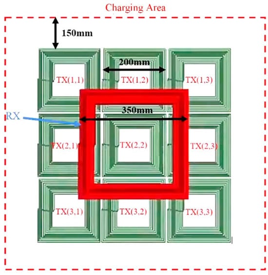
Figure 8.
Coupled mechanism model.
3.2. Transmitting Array Switching Control Strategy Based on Receiving Coil Position Estimation
During the operation of the array UWPT system, due to the influence of water flow disturbance, the position of the underwater electromechanical equipment is not fixed; that is, the receiving coil is prone to offset. Therefore, it is necessary to select the optimal transmitting coil power supply according to the position of the receiving coil to improve the transmission efficiency of the system. In this paper, a transmitting array switching control strategy based on the receiving coil position estimation is proposed. According to the real-time detection of the receiving coil position, the optimal transmitting coil switching control is completed.
3.2.1. Receiver Coil Position Estimation
When the receiving coil is laterally offset relative to the power supply coil, the offset trajectory of the receiving coil and the mutual inductance change curve are shown in Figure 9. It can be seen from the diagram that when the receiving coil gradually moves away from the current power supply coil and is close to the adjacent unpowered coil, the mutual inductance between the power supply coil and it gradually decreases, while the mutual inductance between the unpowered coil and it gradually increases. When moving to a certain position, the two are equal. As the receiving coil continues to move, the mutual inductance between the unpowered coil and it is greater than the mutual inductance between the power supply coil and it. According to the change law of mutual inductance, it can be seen that by comparing the mutual inductance between the power supply coil and the receiving coil and the mutual inductance between the unpowered coil and the receiving coil, the position of the receiving coil can be estimated; that is, the receiving coil is above the transmitting coil with the largest mutual inductance value. Using the same method, it can be verified that when the receiving coil has longitudinal displacement and rotational offset, the position of the receiving coil can be estimated by comparing the mutual inductance values, so as to perform optimal transmitting coil switching control.
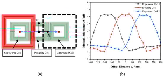
Figure 9.
Receiving coil motion trajectory and mutual inductance change curve. (a) Receiving coil motion trajectory. (b) Mutual inductance change curve.
Because it is difficult to directly measure the mutual inductance during the operation of the system, it is necessary to indirectly compare the mutual inductance between the transmitting coil and the receiving coil by detecting the circuit parameters, and then estimating the position of the receiving coil. The equivalent circuit of the array UWPT system is shown in Figure 10.
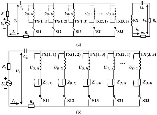
Figure 10.
Equivalent circuit diagram of array UWPT system. (a) System equivalent circuit. (b) Equivalent circuit of transmitting.
In Figure 10, U(x, y) is the voltage at both ends of the transmitting array coil, and Z(x, y) is the reflected impedance of the receiving end. When the transmitting coil TX(x, y) is powered, it can be obtained:
In (1), M(x, y) is the mutual inductance between the power supply coil TX(x, y) and the receiving coil RX. Further, we can obtain:
When the phase difference between Ua and Ia is θ, the expression of the reflection impedance Z(x, y) at the receiving end is as follows:
When the system works in the resonant state, the system impedance angle θ = 0°, the expression of the reflection impedance Z(x, y) at the receiving end can be simplified as follows:
Here, Z(x, y) is defined as the secondary-contributed reflection impedance, calculated as the total primary-side impedance (Ua/Ia) minus the primary coil’s inherent resistance Ra. This isolates the impedance component strictly due to the secondary-receiver coupling, enabling direct comparison of mutual inductance M(x, y) between different transmitting coils. Since Z(x, y) ∝ M(x, y)2 (Equation (4)), comparing Z(x, y) across adjacent coils directly reflects differences in M(x, y), which is critical for estimating the receiver’s position and selecting the optimal transmitting coil.
Since the unpowered coil in the transmitting array is in an open state and no current flows through, the voltage at both ends is induced by the current Ia of the power supply coil and the current Ib of the receiving coil. The voltage U(x+1, y) at both ends of the unpowered coil TX(x+1, y) can be expressed by Ia:
Among them, M(x+1, y) is the mutual inductance between the unpowered coil TX(x+1, y) and the receiving coil, and MTX is the mutual inductance between adjacent coils in the transmitting array. When the coil position in the transmitting array is fixed and the coil parameters are the same, MTX is constant.
According to (5), the reflection impedance Z(x+1, y) at the receiving end is as follows:
Similarly, the expressions of the receiving end reflection impedance Z(x, y+1), Z(x, y−1) and Z(x−1, y) corresponding to the unpowered coils TX(x, y+1), TX(x, y−1) and TX(x−1, y) are as follows:
From (5) to (9), it can be seen that in the expressions of Z(x, y), Z(x+1, y), Z(x, y+1), Z(x, y−1), and Z(x−1, y), only the M(x, y), M(x+1, y), M(x, y+1), M(x, y−1), and M(x−1, y) in the molecules are different, and they are proportional. Therefore, by comparing the size of Z(x, y), Z(x+1, y), Z(x, y+1), Z(x, y−1), and Z(x−1, y), the size relationship of M(x, y), M(x+1, y), M(x, y+1), M(x, y−1), and M(x−1, y) can be indirectly obtained, so as to estimate the position of the receiving coil and realize the optimal power supply coil switching control.
The switching control approach uses reflection impedance Z(x, y) as the metric because Z(x, y) ∝ M(x, y)2, where M(x, y) is the mutual inductance between coils. By comparing Z(x, y) across adjacent coils, we indirectly compare M(x, y), ensuring the coil with the strongest magnetic coupling (highest M(x, y)) is selected. This method avoids direct mutual inductance measurement (complex in underwater environments) while maintaining accuracy.
In summary, this paper proposes a transmit array switching control strategy based on receiving coil position estimation. By comparing the power supply coil TX(x, y) with the four unpowered coils TX(x+1, y), TX(x, y+1), TX(x, y−1), and TX(x−1, y), the receiving end reflection impedance Z(x, y), Z(x+1, y), Z(x, y+1), Z(x, y−1), and Z(x−1, y) of the four unpowered coils TX(x, y), TX(x, y+1), TX(x, y−1), and TX(x−1, y), the position of the receiving coil is estimated, and the coil power supply corresponding to the maximum value of the receiving end reflection impedance Zmax is selected to realize the optimal power supply coil switching control. The expression of Zmax is as follows:
A hysteresis mechanism is incorporated to prevent chattering: the system switches coils only if a neighboring coil’s Z(x, y) exceeds the active coil’s by 5%, ensuring stability near boundaries.
3.2.2. Simulation Verification
Because the effect of longitudinal displacement is similar to that of transverse displacement, the simulation study of longitudinal displacement is omitted. Therefore, based on the above analysis, this section combines Maxwell-Simplorer-Simulink to build a simulation system, selects seawater as the transmission medium, and verifies the initial position estimation method of the receiving coil and the effectiveness of the transmitting array switching control strategy in the case of transverse displacement and two-dimensional offset. The simulation parameters are shown in Table 1.

Table 1.
Experimental Parameters.
For context, MTX = 1.46 μH (adjacent transmitter coils) is 29% of the peak transmitter-receiver mutual inductance M(x, y) ≈ 5 μH (from Figure 7). This moderate coupling is accounted for in calculations but remains small enough to validate the single-coil strategy, as unpowered coils induce minimal voltage compared to active coupling.
- (1)
- Parallel misalignment
When the receiving coil RX is shifted laterally from the top of the transmitting coil TX(2, 2) to the top of the TX(2, 3), the change of the RX trajectory of the receiving coil and the reflection impedance of the receiving end is shown in Figure 11.
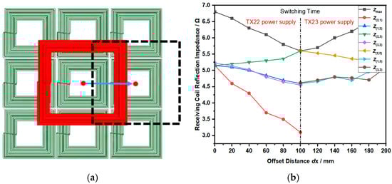
Figure 11.
Simulation result of lateral migration. (a) Receiving coil motion trajectory. (b) Receiver reflection impedance curve.
It can be seen from Figure 11 that the transmitting coil TX(2, 2) is powered at the beginning, and Zmax = Z(2, 2) at this time, while Z(2, 2) gradually decreases with the RX offset. When the transverse displacement distance dx = 100 mm, Zmax = Z(2, 2) = Z(2, 3). As the transverse displacement distance dx continues to increase, Z(2, 3) > Z(2, 2). At this time, Zmax = Z(2, 3), the receiving coil is offset above the transmitting coil TX(2, 3), and the transmitting array is switched to the transmitting coil TX(2, 3) for power supply. After that, dx continues to increase, and Zmax is always equal to Z(2, 3), without switching the power supply coil.
Notably, the Zmax tracking strategy leverages relative comparison of reflection impedances between the active coil and its neighbors, rather than absolute impedance values. This approach inherently reduces sensitivity to measurement noise and environmental variations (e.g., seawater conductivity drift), as such factors affect all coils uniformly and preserve the relative Z(x, y) relationships critical for accurate tracking.
The simulation results show that the transverse displacement of the receiving coil proposed in this paper can achieve the optimal transmitting coil switching control.
- (2)
- 2D Migration
When the receiving coil RX is shifted from the top of the transmitting coil TX(2, 2) to the top of the TX(1, 3), the change of the receiving coil RX trajectory and the receiving end reflection impedance is shown in Figure 12.
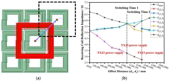
Figure 12.
2D migration simulation results. (a) Receiving coil motion trajectory. (b) Receiver reflection impedance curve.
It can be seen from Figure 12 that the transmitter coil TX(2, 2) is powered at the beginning, and Zmax = Z(2, 2). As RX moves, Z(2, 2) gradually decreases. When the offset distance dx = dy = 100 mm, Zmax = Z(2, 2) = Z(1, 2) = Z(2, 3). As the offset distance dx and dy continue to increase, Z(1, 2) and Z(2, 3) are gradually larger than Z(2,2). At this time, Zmax = Z(1, 2) = Z(2, 3). According to the principle of transmitting array switching control, the transmitting array is switched to the transmitting coil TX(2, 3) for power supply. After that, dx and dy continue to increase, Z(1, 3) > Z(2, 3). At this time, Zmax = Z(1, 3), and the transmitting array is switched to the transmitting coil TX(1,3) for power supply. After that, dx and dy continue to increase, Zmax = Z(1, 3), and there is no need to switch the power supply coil.
The simulation results show that when the two-dimensional offset of the receiving coil RX occurs, the transmitting array switching control strategy based on the position estimation of the receiving coil proposed in this paper can achieve the optimal transmitting coil switching control.
4. Experimental Verification
The experimental design is rooted in real-world AUV requirements. AUVs typically operate in turbulent underwater environments with lateral/longitudinal offsets up to ±200 mm. Thus, we selected a 3 × 3 transmitting array (total size: 600 mm × 600 mm) to cover this range, with coil side length L1 = 200 mm.
Figure 13 shows the experimental platform of the array UWPT system. The main circuit consists of a DC power supply, inverter circuit, compensation network, switch group, coupling mechanism, rectifier circuit, DC-DC conversion circuit, and load. The transmitter control system is composed of a drive circuit, sampling circuit, multiplication phase detection circuit, and controller DSP28335. The receiver control system consists of a sampling circuit, drive circuit, and controller DSP28335.
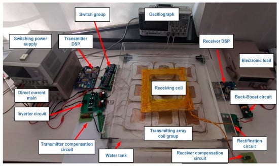
Figure 13.
Experimental platform.
The system’s control subsystem, centered on the DSP28335 microcontroller, enables real-time coil switching. The DSP acquires voltage (Ua) and current (Ia) signals from the sampling circuit, computes reflection impedance Z(x, y), and selects the optimal transmitting coil based on Zmax. The drive circuit amplifies the DSP’s control signals to activate the inverter and coil relays. The multiplication phase detection circuit measures the phase difference θ between Ua and Ia, enabling calculation of Z(x, y) for receiver position estimation and coil switching.
The experimental platform was configured in a seawater tank with controlled conditions (salinity: 35‰, temperature: 10 ± 1 °C). The transmitting array (3 × 3 square coils, L1 = 200 mm) and receiving coil (L2 = 350 mm) were precisely controlled lateral (dx) and longitudinal (dy) offsets. Voltage and current measurements were acquired using an oscilloscope and Hall-effect sensors.
The transmitting and receiving coils are made of Litz wire and are designed to be waterproof to reduce corrosion from seawater. Coil temperatures were monitored via surface thermocouples during experiments, with maximum rises limited to 10 °C under rated power, confirming stable operation.
Efficiency measurements were conducted under a rated power of 300 W with a fixed load resistance RL = 20 Ω. The main parameters of the experimental platform are shown in Table 1.
4.1. Lateral Shift Experiment
When the receiving coil RX is shifted laterally from the top of the transmitting coil TX(2, 2) to the top of the TX(2, 3), the experimental results of the reflection impedance of the receiving end and the transmission efficiency of the system are shown in Figure 14.
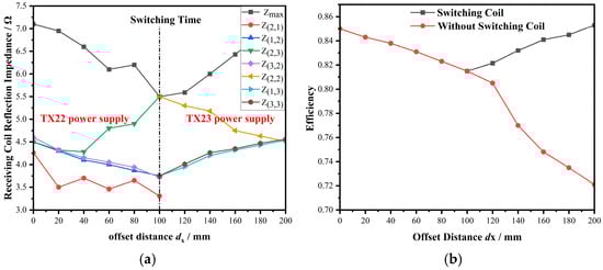
Figure 14.
Experiment results of transverse displacement. (a) Receiver reflection impedance curve. (b) Transmission efficiency curve.
The efficiency was calculated as η = Pout/Pin × 100%, where Pout (load power) and Pin (input power) were measured using a power analyzer.
It can be seen from Figure 14 that the transmitting coil TX(2, 2) is powered at the beginning, and Zmax = Z(2, 2) at this time, and the system transmission efficiency is the highest. As the transverse displacement distance dx increases, Z(2, 2) gradually decreases, and the system transmission efficiency gradually decreases. When the transverse displacement distance dx = 100 mm, Zmax = Z(2, 2), and the system transmission efficiency is the smallest. As the transverse displacement distance dx continues to increase, Z(2, 3) > Z(2, 2). At this time, Zmax = Z(2, 3), the receiving coil is offset to the top of the transmitting coil TX(2, 3), and the transmitting array is switched to the transmitting coil TX(2, 3) for power supply.
After the coil switching is completed, as the transverse displacement distance dx continues to increase, Zmax = Z(2, 3), the system transmission efficiency increases, and there is no need to switch the power supply coil. The experimental results show that when the transverse displacement of the receiving coil RX occurs, the transmitting array switching control strategy based on the position estimation of the receiving coil proposed in this paper can achieve the optimal transmitting coil switching control, and the system transmission efficiency is maintained above 80%.
4.2. 2D Migration
For the 2D migration test, the receiving coil was moved from the initial position (centered over TX(2, 2)) to the target position (centered over TX(1, 3)) along a diagonal trajectory (dx = dy, from 0 to 200 mm). At each offset step (Δdx = Δdy = 20 mm), the system was stabilized for 5 s to ensure steady-state operation. The reflection impedance Z(x, y) of the active coil and its neighbors (TX(1, 2), TX(2, 3), TX(1, 3)) was recorded.
The experimental results of the receiving end reflection impedance and the system transmission efficiency are shown in Figure 15.
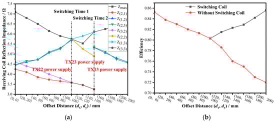
Figure 15.
2D migration experiment. (a) Receiver reflection impedance curve. (b) Transmission efficiency curve.
It can be seen from Figure 15 that the transmitting coil TX(2, 2) is powered at the beginning, and Zmax = Z(2, 2) at this time, and the system transmission efficiency is the highest. As the offset distance dx and dy increase, Z(2, 2) gradually decreases, and the system transmission efficiency decreases. When the offset distance dx = 100 mm, dy = 100 mm, Zmax = Z(2, 2), and the system transmission efficiency is the smallest. As the offset distance dx and dy continue to increase, Z(1, 2) and Z(2, 3) gradually become larger than Z(2, 2), Zmax = Z(2, 3). According to the control principle of transmitting array switching, the transmitting array is switched to the transmitting coil TX(2, 3) for power supply.
After the coil switching is completed, as the offset distance dx and dy continue to increase, Z(1, 3) > Z(2, 3). At this time, Zmax = Z(2, 3), the transmitting array is switched to the transmitting coil TX(1, 3) for power supply, and the secondary switching of the transmitting array is completed.
After the second switching, as the offset distance dx and dy continue to increase, Zmax = Z(1, 3), the system transmission efficiency gradually increases, and there is no need to switch the power supply coil. The experimental results show that when the two-dimensional offset of the receiving coil RX occurs, the transmitting array switching control strategy based on the position estimation of the receiving coil proposed in this paper can achieve the optimal transmitting coil switching control, and the system transmission efficiency is maintained above 80%. Notably, at dx = dy = 100 mm (midpoint), the system switched from TX(2, 2) to TX(2, 3) due to Z(2, 3) > Z(2, 2), and later to TX(1, 3) at dx = dy = 150 mm, confirming the robustness of the switching strategy under combined lateral and longitudinal offsets.
Experimental validation was also conducted in a seawater tank, confirming that the designed system maintains high efficiency (>80%) even when accounting for seawater-induced losses.
5. Conclusions
To enhance the anti-offset ability of the underwater wireless power transfer system and improve the transmission efficiency of the system, this paper proposes a coupling mechanism design method and a transmitting array switching control strategy for the array underwater wireless power transfer system. By analyzing the influence of the size ratio of the transmitting coil and the receiving coil on the mutual inductance change when the system is offset, the optimal size ratio of the transmitting coil and the receiving coil is determined.
By comparing the reflection impedance of the receiving end of the power supply coil and its surrounding adjacent coils, the position of the receiving coil is estimated, so as to realize the optimal power supply coil switching. The theoretical method studied in this paper was verified by experiments. The experimental results show that the UWPT system designed in this paper can expand the proposed receiving coil position estimation method and transmitting array switching control method. When the receiving coil is offset, the optimal transmitting coil switching control can be realized according to the position of the receiving coil, and the transmission efficiency of the system is maintained above 80%.
Notably, receiver-side adaptation (e.g., DC-DC control or variable load regulation) could further enhance system performance by optimizing impedance matching and stabilizing output power under misalignment. While this work focuses on transmitter-side array design to expand the anti-offset range, integrating receiver-side control is a promising direction for future research to achieve even higher efficiency and power stability.
Author Contributions
H.X.: Methodology, Software, Investigation, Validation, Formal Analysis, Visualization, Writing—Original Draft; W.L.: Conceptualization, Funding Acquisition, Resources, Supervision, Writing—Review & Editing; Z.Z.: Conceptualization, Methodology, Supervision, Writing—Review & Editing; Y.W.: Software, Validation, Visualization, Writing—Original Draft. All authors have read and agreed to the published version of the manuscript.
Funding
This research received no external funding.
Institutional Review Board Statement
Not applicable.
Informed Consent Statement
Not applicable.
Data Availability Statement
The original contributions presented in this study are included in the article. Further inquiries can be directed to the corresponding author.
Conflicts of Interest
No conflicts of interest exist in the submission of this manuscript. I would like to declare that the work described was original research that has not been published previously, and not under consideration for publication elsewhere.
References
- Page, B.R.; Mahmoudian, N. Simulation-Driven Optimization of Underwater Docking Station Design. IEEE J. Ocean. Eng. 2020, 45, 404–413. [Google Scholar] [CrossRef]
- Lin, M.; Lin, R.; Li, D.; Yang, C. Light Beacon-Aided AUV Electromagnetic Localization for Landing on a Planar Docking Station. IEEE J. Ocean. Eng. 2023, 48, 677–688. [Google Scholar] [CrossRef]
- Jyothi, V.B.N.; Akash, S.J.; Ramadass, G.A.; Vedachalam, N.; Venkataraman, H. Design and Development of Deep Learning-Aided Vision Guidance System for AUV Homing Applications. IEEE Embed. Syst. Lett. 2024, 16, 198–201. [Google Scholar] [CrossRef]
- Ann, S.; Lee, B.K. Analysis of Impedance Tuning Control and Synchronous Switching Technique for a Semibridgeless Active Rectifier in Inductive Power Transfer Systems for Electric Vehicles. IEEE Trans. Power Electron. 2021, 36, 8786–8798. [Google Scholar] [CrossRef]
- Kim, H.; Kim, J.; Ahn, J.; Shin, Y.; Park, B.; Huh, S.; Choi, S.; Park, J.; Ahn, S. Determination of Compensation Capacitor Considering the Dead-Time Characteristics for ZVS in Wireless Power Transfer System. IEEE J. Emerg. Sel. Top. Power Electron. 2023, 11, 2501–2513. [Google Scholar] [CrossRef]
- Luo, J.; Chen, K.; Ouyang, Y.; Hong, Y.; Pan, J.F. Dynamic Control of Power Supply for Distance Changing in Underwater Wireless Power Transfer. In Proceedings of the 2022 IEEE 9th International Conference on Power Electronics Systems and Applications (PESA), Hong Kong, China, 20 September 2022; pp. 1–5. [Google Scholar]
- Zhou, H.; Shen, Z.; Wu, Y.; Zhuang, Y.; Zhang, Y. An Anti-Misalignment Wireless Charging System for Low-Power Applications Based on Solenoid Coils Incorporated with Reverse Windings. IEEE Trans. Consum. Electron. 2024, 70, 371–377. [Google Scholar] [CrossRef]
- Yang, Y.; Zhong, W.; Kiratipongvoot, S.; Tan, S.-C.; Hui, S.Y.R. Dynamic Improvement of Series–Series Compensated Wireless Power Transfer Systems Using Discrete Sliding Mode Control. IEEE Trans. Power Electron. 2018, 33, 6351–6360. [Google Scholar] [CrossRef]
- Colak, K.; Asa, E.; Bojarski, M.; Czarkowski, D.O.C. Onar A Novel Phase-Shift Control of Semibridgeless Active Rectifier for Wireless Power Transfer. IEEE Trans. Power Electron. 2015, 30, 6288–6297. [Google Scholar] [CrossRef]
- Diekhans, T.; De Doncker, R.W. A Dual-Side Controlled Inductive Power Transfer System Optimized for Large Coupling Factor Variations and Partial Load. IEEE Trans. Power Electron. 2015, 30, 6320–6328. [Google Scholar] [CrossRef]
- Yang, L.; Zhang, B.; Ju, M. A Fast Dynamic Response Regulation Method for Undersea Wireless Power Transfer System. In Proceedings of the 2019 14th IEEE Conference on Industrial Electronics and Applications (ICIEA), Xi’an, China, 19–21 June 2019; pp. 1162–1166. [Google Scholar]
- Lu, F.; Zhang, H.; Hofmann, H.; Mi, C.C. A Dynamic Charging System with Reduced Output Power Pulsation for Electric Vehicles. IEEE Trans. Ind. Electron. 2016, 63, 6580–6590. [Google Scholar] [CrossRef]
- Tan, P.; Peng, T.; Gao, X.; Zhang, B. Flexible Combination and Switching Control for Robust Wireless Power Transfer System with Hexagonal Array Coil. IEEE Trans. Power Electron. 2021, 36, 3868–3882. [Google Scholar] [CrossRef]
- Kan, T.; Zhang, Y.; Yan, Z.; Mercier, P.P.; Mi, C.C. A Rotation-Resilient Wireless Charging System for Lightweight Autonomous Underwater Vehicles. IEEE Trans. Veh. Technol. 2018, 67, 6935–6942. [Google Scholar] [CrossRef]
- Li, Y.; Xie, K.; Ying, Y. A Novel Magnetic Coupler with Low Leakage EMF for AUV Wireless Power Transfer System. IEEE J. Emerg. Sel. Top. Ind. Electron. 2024, 5, 212–224. [Google Scholar] [CrossRef]
- Kim, J.; Kim, D.-H.; Park, Y.-J. Free-Positioning Wireless Power Transfer to Multiple Devices Using a Planar Transmitting Coil and Switchable Impedance Matching Networks. IEEE Trans. Microw. Theory Tech. 2016, 64, 3714–3722. [Google Scholar] [CrossRef]
- Cai, C.; Zhang, Y.; Wu, S.; Liu, J.; Zhang, Z.; Jiang, L. A Circumferential Coupled Dipole-Coil Magnetic Coupler for Autonomous Underwater Vehicles Wireless Charging Applications. IEEE Access 2020, 8, 65432–65442. [Google Scholar] [CrossRef]
- Guo, K.; Zhou, J.; Sun, H.; Yao, P. Design Considerations for a Position-Adaptive Contactless Underwater Power Deliver System. In Proceedings of the 2019 22nd International Conference on Electrical Machines and Systems (ICEMS), Harbin, China, 11–14 August 2019; pp. 1–6. [Google Scholar]
- Wang, D.; Chen, F.; Zhang, J.; Cui, S.; Bie, Z.; Zhu, C. A Novel Pendulum-Type Magnetic Coupler with High Misalignment Tolerance for AUV Underwater Wireless Power Transfer Systems. IEEE Trans. Power Electron. 2023, 38, 14861–14871. [Google Scholar] [CrossRef]
- Wu, S.; Cai, C.; Chai, W.; Li, J.; Cui, Q.; Yang, S. Uniform Power IPT System with Quadruple-Coil Transmitter and Crossed Dipole Receiver for Autonomous Underwater Vehicles. IEEE Trans. Ind. Appl. 2022, 58, 1289–1297. [Google Scholar] [CrossRef]
- Xu, J.; Li, X.; Li, H.; Xie, Z.; Ma, Q. Maximum Efficiency Tracking for Multi-transmitter Multi-receiver Wireless Power Transfer System on the Submerged Buoy. IEEE Trans. Ind. Electron. 2022, 69, 1909–1919. [Google Scholar] [CrossRef]
- Wang, T.; Zhao, Q.; Yang, C. Visual navigation and docking for a planar type AUV docking and charging system. Ocean. Eng. 2021, 224, 108744. [Google Scholar] [CrossRef]
- Pahlavan, S.; Shooshtari, M.; Ashtiani, S.J. Star-Shaped Coils in the Transmitter Array for Receiver Rotation Tolerance in Free-Moving Wireless Power Transfer Applications. Energies 2022, 15, 8643. [Google Scholar] [CrossRef]
- Sato, N.; Kifune, H.; Komeda, S. A coil layout of wireless power transfer systems based on multi-coil arrangement for underwater vehicles. Electr. Eng. 2019, 207, 38–48. [Google Scholar] [CrossRef]
- Hasaba, R.; Eguchi, K.; Yamaguchi, S.; Satoh, H.; Yagi, T.; Koyanagi, Y. WPT System in Seawater for AUVs with kW-Class Power, High Positional Freedom, and High Efficiency Inside the Transfer Coils. In Proceedings of the 2022 Wireless Power Week (WPW), Bordeaux, France, 5–8 July 2022; pp. 90–94. [Google Scholar]
Disclaimer/Publisher’s Note: The statements, opinions and data contained in all publications are solely those of the individual author(s) and contributor(s) and not of MDPI and/or the editor(s). MDPI and/or the editor(s) disclaim responsibility for any injury to people or property resulting from any ideas, methods, instructions or products referred to in the content. |
© 2025 by the authors. Licensee MDPI, Basel, Switzerland. This article is an open access article distributed under the terms and conditions of the Creative Commons Attribution (CC BY) license (https://creativecommons.org/licenses/by/4.0/).