Article

Event-Triggered Active Fault-Tolerant Predictive Control for Networked Multi-Agent Systems with Actuator Faults and Random Communication Constraints

1
Key Laboratory of Field Bus Technology and Automation of Beijing, North China University of Technology, Beijing 100144, China
2
School of Electrical and Control Engineering, Henan University of Urban Construction, Pingdingshan 467000, China
*
Author to whom correspondence should be addressed.
Appl. Sci. 2025, 15(11), 6317; https://doi.org/10.3390/app15116317
Submission received: 11 March 2025 / Revised: 27 May 2025 / Accepted: 31 May 2025 / Published: 4 June 2025
(This article belongs to the Section Robotics and Automation)

Abstract

This paper proposes a composite control method that integrates an active fault-tolerant predictive control scheme and an event-triggered mechanism for networked multi-agent systems. The approach considers random communication constraints in the forward and feedback channels as well as actuator faults. At each time instant, the event trigger determines whether to send system outputs based on the current system state. A Kalman filter is then utilized to estimate both the system state and potential faults by incorporating system output information transmitted through the feedback channel. Concurrently, iterative predictions are performed according to the established system model. Furthermore, a predictive sequence of control inputs is generated through the designed control protocol. Leveraging timestamping technology, the system precisely applies the appropriate control commands to the actuator at designated moments. As a result, the proposed control method compensates for both random communication constraints and actuator faults while effectively reducing data transmission over the communication network. Finally, the proposed method is validated through numerical simulations.

1. Introduction

Networked multi-agent systems (NMASs) have garnered substantial attention in recent decades due to their broad applicability across diverse industries, including unmanned aerial vehicles and unmanned surface vessels [1,2,3]. In NMASs, agents are interconnected via communication networks, enabling interaction with the environment and collaboration on complex tasks. However, this interconnectedness also impacts their performance and reliability.
Random communication constraints (RCCs) and actuator faults are two common challenges for NMASs. RCCs arise from various factors such as packet loss, communication delays, and intermittent connectivity, which are inherent in wireless communication environments [4,5,6]. These constraints can disrupt the flow of information between agents, leading to inaccurate state estimation and suboptimal control decisions. For addressing RCCs, different strategies have been explored. A switched system approach with mode-dependent state feedback controllers was proposed in [7] to improve system performance under RCCs, but it did not explicitly account for actuator faults. A fuzzy fault diagnosis observer was devised in [8] to estimate unknown multiplicative faults under RCCs, yet it did not address network congestion issues. Cloud-based predictive control approaches, such as the one in [9], have been proposed to compensate for RCCs in both feedback and forward channels, but they may introduce additional computational overhead. Additionally, the prolonged operation of NMASs in harsh external environments often results in actuator faults, such as partial failures or bias errors [10,11]. Such faults can propagate throughout the tightly coupled system, potentially destabilizing the entire network and compromising mission success. Previous research has proposed various fault-tolerant control (FTC) methods for NMASs. Passive FTC approaches, such as that developed in [12], rely on fixed controllers without dynamic fault compensation, which may lack the flexibility to adapt to changing fault conditions. In contrast, active FTC methods, like those in [13,14], actively estimate and compensate for faults, but they often do not adequately consider the impact of RCCs on fault estimation accuracy. Distributed adaptive control schemes, such as the one introduced in [15], aim to achieve fault-tolerant coordination and collision avoidance, but they may not be optimized for communication efficiency in the presence of network congestion. The large volume of data transfers required for communication among agents can lead to network congestion, consuming the limited bandwidth of the communication network [16]. This congestion not only degrades the system’s performance but can also cause instability, as delays in data transmission and control updates become more pronounced [17]. In terms of network congestion, event-triggered control mechanisms have been applied to reduce data transmission [18,19]. For instance, in [20], a dynamic memory event-triggered mechanism and memory-based distributed fault-tolerant controllers were developed to reduce the number of events triggered. However, these methods may not fully consider the complex interactions between RCCs, actuator faults, and the need for fault-tolerant control.
Despite extensive research efforts, addressing these three challenges simultaneously in NMASs remains an open and critical problem [21]. Although many studies have focused on individual aspects of these challenges, there is a notable lack of comprehensive solutions that can effectively mitigate the combined effects of RCCs, actuator faults, and network congestion. The research gap identified in this study is the lack of a unified control method that can simultaneously address RCCs, actuator faults, and network congestion in NMASs. Previous approaches have either focused on individual challenges or have not fully integrated fault-tolerant control with communication efficiency mechanisms. This gap is significant because in real-world applications, NMASs often operate in environments where all three challenges are present, and a comprehensive solution is essential for ensuring system reliability and performance.
To address this gap, this paper proposes an event-triggered active fault-tolerant predictive control method for NMASs. The proposed method aims to simultaneously mitigate the effects of RCCs, compensate for actuator faults, and reduce network congestion by optimizing data transmission. The novelty and significance of the proposed method lie in its comprehensive integration of three key components: event-triggered control, active fault-tolerant control, and predictive control. By utilizing an event-triggered mechanism, the method dynamically adjusts the data transmission schedule based on the current system state, thereby reducing the amount of data sent over the feedback channel and alleviating network congestion. This is in contrast to traditional time-triggered methods that transmit data at fixed intervals, regardless of the system’s actual needs. The active fault-tolerant control aspect of the proposed method involves actively estimating and compensating for actuator faults using a Kalman filter. By integrating system output information conveyed through the feedback channel, the method can accurately estimate both the system state and potential faults, thereby facilitating timely and effective fault compensation. This represents an enhancement over passive FTC methods that lack dynamic fault compensation capabilities. The predictive control component of the proposed method conducts iterative predictions based on the established system model and generates a predictive sequence of control inputs. These inputs are precisely applied to the actuators at designated moments using timestamping technology, ensuring that the system can adapt to changing conditions and maintain stability even in the presence of RCCs and actuator faults.
Compared with existing solutions, particularly the method presented in [21], a flexible event-triggered mechanism is proposed to reduce the communication burden of the feedback channel. The main advantages and contributions of the proposed method can be summarized as follows. First, it provides a unified framework for addressing RCCs, actuator faults, and network congestion, representing a significant advancement over previous approaches that have focused on individual challenges. Second, the event-triggered mechanism reduces data transmission without compromising system performance, making it more suitable for resource-constrained communication networks. Third, the proposed method comprehensively considers dual-channel communication constraints and actuator faults, and the stability condition of closed-loop system is derived.

2. Control Scheme Design

The topology between agents can be represented by a directed graph G = ( V , E , A ) , where V = { v 1 , v 2 , , v N } and E = { ( v i , v j ) : v i , v j V } denote the vertex set and the edge set, respectively. A = [ a i j ] represents a non-negative adjacency matrix with a i i = 0 .
Consider a second-order discrete-time NMAS with a virtual leader and N followers
x i ( t + 1 ) = A i x i ( t ) + B i u i ( t ) + F i f i ( t ) + ω i ( t ) y i ( t ) = C i x i ( t ) + υ i ( t ) ,
where x i R n , u i R m , f i R q , y i R p are the state, the input, the actuator fault and the system output of agent i, i = 1 , 2 , , N , respectively. The system matrices are represented by A i , B i , C i and F i which have the corresponding dimension. Suppose that ( A i , B i ) is controllable, and ( A i , C i ) is observable. ω i ( t ) N ( 0 , Q i ) and υ i ( t ) N ( 0 , R i ) are process noise and measurement noise, respectively.
The purpose of the designed control method is to allow the leader to track the reference signal r ( t ) , which provides a common benchmark for all agents. Furthermore, to enable the follower to track the leader and maintain the desired output tracking error, the tracking error of agent i is defined as
e i ( t ) = r ( t ) y i ( t ) , i = 1 y i ( t ) y 1 ( t ) , i 1 ,
where e 1 ( t ) denotes the error of the leader in tracking r ( t ) , and e i ( t ) ( i 1 ) denotes the tracking error of the follower in tracking the leader.
From (1) and (2), it can be deduced that the output tracking error of agent i has the following relationship
e i ( t + 1 ) = e i ( t ) + Δ r ( t + 1 ) C i A i Δ x i ( t ) C i B i Δ u i ( t ) C i F i Δ f i ( t ) C i Δ ω i ( t ) Δ υ i ( t + 1 ) , i = 1 e i ( t ) + Δ y 1 ( t + 1 ) C i A i Δ x i ( t ) C i B i Δ u i ( t ) C i F i Δ f i ( t ) C i Δ ω i ( t ) Δ υ i ( t + 1 ) , i 1 ,
where the symbol Δ represents the forward difference. For example, Δ r ( t + 1 ) = r ( t + 1 ) r ( t ) . Then, combining (1) and (3), the following tracking error augmentation system can be obtained
x e , i ( t + 1 ) = A e , i x e , i ( t ) + B e , i Δ u i ( t ) + F e , i Δ f i ( t ) + E e , i Δ r ( t + 1 ) + I e , i Δ ω i ( t ) E e , i Δ υ i ( t + 1 ) , i = 1 A e , i x e , i ( t ) + B e , i Δ u i ( t ) + F e , i Δ f i ( t ) + E e , i Δ y 1 ( t + 1 ) + I e , i Δ ω i ( t ) E e , i Δ υ i ( t + 1 ) , i 1
Δ y i ( t ) = C e , i x e , i ( t ) ,
where x e , i ( t ) = Δ x i ( t ) e i ( t ) R n + p , A e , i = A i 0 C i A i I , B e , i = B i C i B i , C e , i = C i 0 , E e , i = 0 I , F e , i = F i C i F i , I e , i = I C i . I represent the identity matrix with suitable dimensions, and similarly, 0 is a zero matrix with appropriate dimensions. When the NMAS (1) is in a steady state, the tracking error broadening system exists with lim t x e , i ( t ) = 0 . Therefore, the tracking control issue can be reframed as a common asymptotic stabilization problem.
The considered actuator faults are slow time-varying and can therefore be approximated as the following equation
f i ( t + 1 ) = f i ( t ) .
With (1) and (6), it can be obtained that
x f , i ( t + 1 ) = A f , i x f , i ( t ) + B f , i u i ( t ) + I f ω i ( t ) y i ( t ) = C f , i x f , i ( t ) + υ i ( t ) ,
where x f , i ( t ) = x i ( t ) f i ( t ) R q , A f , i = A i F i 0 I , B f , i = B i 0 , C f , i = C i 0 , I f = I 0 .
Furthermore, the two assumptions below are also necessary.
Assumption 1. 
The sensor, controller, and actuator of each agent operate in the time-driven and synchronous manner.
Assumption 2. 
Random network delays τ t , i ca and τ t , i sc in both the forward and feedback channels of each agent are bounded, i.e., 0 τ t , i ca τ ¯ ca and 0 τ t , i sc τ ¯ sc , where τ ¯ ca and τ ¯ sc are non-negative integers.
An event-triggered networked predictive fault-tolerant control (ENPFTC) scheme is designed to reduce unnecessary data transmission in the feedback channel, and compensate for actuator faults and the random communication constraints in the feedback and forward channels, as shown in Figure 1.
Event triggers use a static triggering mechanism with the following event triggering conditions
T φ + 1 = min { t | ( y i ( t ) y i ( T φ ) ) T N i ( y i ( t ) y i ( T φ ) ) > η i y i ( t ) T N i y i ( t ) } ,
where T ϕ is the trigger moment, η i is a scalar parameter, and N i is a matrix to be designed. In addition, to avoid event triggers going un-triggered for long periods of time, it is necessary to make T φ + 1 T φ + W i , which W i is the maximum trigger interval. Upon satisfying condition (8), the information of the agent is transmitted to the Kalman filter through the network, and then generates a set of control sequences by the predictive fault-tolerant controller, otherwise not transmitted as a way to conserve network resources. Furthermore, event triggers will introduce an additional delay which is defined as τ t , i e , where τ t , i e W i . The feedback channel’s total delay of the agent is then denoted as τ t , i e s , where τ t , i e s = τ t , i sc + τ t , i e , and where 0 τ t , i e s τ ¯ sc + W i .
Remark 1. 
If trigger conditions are too lenient, delayed responses may occur. If too strict, resource consumption rises. By tuning η i and N i while monitoring response latency and trigger frequency, an optimal balance point can be identified, determining the parameter values of η i and N i .
Predictive fault-tolerant controllers are designed in the control loop of each agent, event triggers are designed after the sensors, and delay compensators are designed in the actuators. Using the Kalman filter can estimate both the state and the actuator faults of the agent simultaneously
x ^ f , i ( t τ t 1 , i es + h i | t τ t 1 , i es + h i 1 ) = A f , i x ^ f , i ( t τ t 1 , i es + h i 1 | t τ t 1 , i es + h i 2 ) + B f , i u i ( t τ t 1 , i es + h i 1 ) + K i ( y i ( t τ t 1 , i es + h i ) C f , i ( A f , i x ^ f , i ( t τ t 1 , i es + h i 1 | t τ t 1 , i es + h i 2 ) + B f , i u i ( t τ t 1 , i es + h i 1 ) ) ) ,
where h i = 0 , 1 , , τ t 1 , i es τ t , i es , x ^ f , i ( t τ t 1 , i es + h i ) = x ^ f , i ( t τ t 1 , i es + h i | t τ t 1 , i es + h i 1 ) is the estimate of the state and actuator faults, and K i = lim t K i ( t ) is the gain of the Kalman filter with
K i ( t ) = P i ( t | t 1 ) C f , i T ( C f , i P i ( t | t 1 ) C f , i T + R i ) 1 P i ( t | t 1 ) = A f , i P i ( t 1 | t 1 ) A f , i T + Q i ¯ P i ( t | t ) = ( I n 1 K i ( t ) C f , i ) P i ( t | t 1 ) ,
where n 1 = n + p , Q i ¯ = diag { Q i , Q R i } and Q R i R p × p > 0 .
When t τ t , i e s t τ t 1 , i e s 1 , the controller does not receive updated output data of the agent, and the estimate state and the actuator fault of the agent remain the same as the previous moment
x ^ f , i ( t τ t , i e s | t τ t , i e s 1 ) = x ^ f , i ( t τ t 1 , i e s 1 | t τ t 1 , i e s 2 ) .
Combining the state estimate of agent i and (4), the error and state prediction and output incremental prediction for agent i can be obtained as follows
x ^ e , 1 ( t τ t , 1 es + h 1 | t τ t , 1 es 1 ) = A e , 1 x ^ e , 1 ( t τ t , 1 es + h 1 1 | t τ t , 1 es 1 ) + B e , 1 Δ u 1 ( t τ t , 1 es + h 1 1 ) + F e , 1 Δ f ^ 1 ( t τ t , 1 es | t τ t , 1 es 1 ) + E e , i Δ r ( t τ t , 1 es + h 1 ) ,
x ^ e , i ( t τ t , i es + h i | t τ t , i es 1 ) = A e , i x ^ e , i ( t τ t , i es + h i 1 | t τ t , i es 1 ) + B e , i Δ u i ( t τ t , i es + h i 1 ) + F e , i Δ f ^ i ( t τ t , i es | t τ t , i es 1 ) + E e , i Δ y ^ 1 ( t τ t , i es + h i | t τ t , i es ) , i 1 ,
Δ y ^ e , i ( t τ t , i es + h i | t τ t , i es ) = C e , i x ^ e , i ( t τ t , i es + h i | t τ t , i es 1 ) ,
where h i = 1 , 2 , , τ t , i es + τ ¯ ca , x ^ e , i ( t τ t , i es + h i | t τ t , i es 1 ) = [ Δ x ^ i T ( t τ t , i es + h i | t τ t , i es 1 ) , e ^ i T ( t τ t , i es + h i | t τ t , i es ) ] T , Δ f ^ i ( t τ t , i es | t τ t , i es 1 ) = I x Δ x ^ f , i ( t τ t , i es | t τ t , i es 1 ) , I x = [ 0 I ] .
In order to realize the output tracking control of the system, the incremental control law of agent i is designed by combining (12)–(14) as follows
Δ u i ( t + τ ¯ ca ) = L i a x ^ e , i ( t + τ ¯ ca | t τ t , i es 1 ) B e , i + F e , i Δ f ^ i ( t τ t , i es | t τ t , i es 1 ) + L i b j = 1 j i N a i j ( y ^ j ( t + τ ¯ ca | t τ t , j es ) Δ y ^ i ( t + τ ¯ ca | t τ t , i sc ) ) ,
u i ( t + τ ¯ ca ) = u i ( t + τ ¯ ca 1 ) + Δ u i ( t + τ ¯ ca ) ,
where L i a and L i b are the controller to be determined, B e , i + is the generalized inverse of B e , i .
From the control input prediction sequences U i ( t ) = [ u i T ( t ) u i T ( t + 1 ) u i T ( t + τ ¯ ca ) , t ] T , the appropriate control command is selected and applied to the actuator to compensate for the random communication constraints in the forward channel, i.e.,
Δ u i ( t ) = L i a x ^ e , i ( t | t τ t , i 1 ) + L i b j = 1 j i N a i j ( Δ y ^ j ( t | t τ t , j ) Δ y ^ i ( t | t τ t , i ) ) B e , i + F e , i Δ f ^ i ( t | t τ t , i ) ,
where τ t , i = τ t τ ¯ ca , i es + τ ¯ ca , τ t , j = τ t τ ¯ ca , j es + τ ¯ ca .

3. Stability Analysis

Based on the considered system model and the proposed control law in the control scheme, the following theorem is obtained.
Theorem 1. 
The stability of the closed-loop system resulting from Equations (1), (9), (10) and (17), i.e., the control objective, is guaranteed if and only if the eigenvalues of Ω and Γ are lie inside the unit circle, where the matrices Ω and Γ are described by
Ω = A e , 1 B e , 1 c 1 B e , 1 d 12 B e , 2 d 21 + E e , 2 C e , 1 ( A e , 1 B e , 1 c 1 ) A e , 2 B e , 2 c 2 B e , N d N 1 + E e , N C e , 1 ( A e , 1 B e , 1 c 1 ) B e , N d N 2 + E e , N C e , 1 B e , 1 d 12 B e , 1 d 1 N B e , 2 d 2 N + E e , 2 C e , 1 B e , 1 d 1 N A e , N B e , N c N ,
Γ = diag { I n 1 K 1 C f , 1 , , I n 1 K 1 C f , 1 τ t , 1 + 1 , , I n 1 K N C f , N , , I n 1 K N C f , N } τ t , N + 1 .
Proof. 
The reference signal, without any loss of generality, is set as r ( · ) = 0 . The estimation error of agent i about the state and fault can be expressed as follow
x ˜ f , i ( t ) = x f , i ( t ) x ^ f , i ( t | t 1 ) .
According to (7), (9) and (18), it can be deduced that the estimation error of agent i has the following relationship
x ˜ f , i ( t + 1 ) = ( I n 1 K i C f , i ) ( A f , i x ˜ f , i ( t ) + I f ω i ( t ) ) K i υ i ( t + 1 ) ,
and then it can be obtained that
x ^ f , i ( t + 1 | t ) = A f , i x ^ f , i ( t | t 1 ) + B f , i u i ( t ) + K i C f , i A f , i x ˜ f , i ( t ) + K i C f , i I f ω i ( t ) + K i υ i ( t + 1 ) .
Iterative computation from (4) and (12) yields the actual error broadening state and the predicted value of the error broadening state of the leader at moment t
x e , 1 ( t ) = A e , 1 τ t , 1 es x e , 1 ( t τ t , 1 es ) + s 1 = 1 τ t , 1 es A e , 1 s 1 1 ( B e , 1 Δ u 1 ( t s 1 ) + F e , 1 Δ f 1 ( t s 1 ) ) + s 1 = 1 τ t , 1 es A e , 1 s 1 1 ( I e , 1 Δ ω 1 ( t s 1 ) E e , 1 Δ υ 1 ( t + 1 s 1 ) ) ,
x ^ e , 1 ( t | t τ t , 1 es 1 ) = A e , 1 τ t , 1 es x ^ e , 1 ( t τ t , 1 es | t τ t , 1 es 1 ) + s 1 = 1 τ t , 1 es A e , 1 s 1 1 ( B e , 1 Δ u 1 ( t s 1 ) + F e , 1 Δ f ^ 1 ( t s 1 | t s 1 1 ) ) ,
where, according to (6), we define Δ f ^ i ( t | t 1 ) = Δ f i ( t ) = I x x ˜ f , i ( t ) .
Taking (21) minus (22) gives the result
x e , 1 ( t ) x ^ e , 1 ( t | t τ t , 1 es 1 ) = A e , 1 τ t , 1 es I ¯ x ˜ 1 ( t τ t , 1 es ) + s 1 = 1 τ t , 1 es A e , 1 s 1 1 ( I e , 1 Δ ω 1 ( t s 1 ) E e , 1 Δ υ 1 ( t + 1 s 1 ) ) ,
where I ¯ = I 0 T . Subtracting (14) from (5) and combining it with (23), can obtain
Δ y 1 ( t ) Δ y ^ 1 ( t | t τ t , 1 es ) = C e , 1 A e , 1 τ t , 1 es I ¯ x ˜ 1 ( t τ t , 1 es ) + C e , 1 s 1 = 1 τ t , 1 es A e , 1 s 1 1 ( I e , 1 Δ ω 1 ( t s 1 ) E e , 1 Δ υ 1 ( t + 1 s 1 ) ) .
According to the derivation of (23) and (24), the actual as well as the prediction error broadening state of the follower can be obtained
x e , i ( t ) x ^ e , i ( t | t τ t , i es 1 ) = A e , i τ t , i es I ¯ x ˜ i ( t τ t , i es ) + δ i ( t ) x ˜ 1 ( t τ t , i es ) + s i = 1 τ t , 1 es A e , i s i 1 ( I e , i Δ ω i ( t s i ) E e , i Δ υ i ( t + 1 s i ) ) + s i = 0 τ t , i es min 1 A e , i s i E e , i C e , i s 1 = 1 τ t , 1 es A e , 1 s 1 1 ( I e , 1 Δ ω 1 ( t s 1 ) E e , 1 Δ υ 1 ( t + 1 s 1 ) ) ,
where δ i ( t ) = s i = 0 τ t , i es min 1 A e , i s i E e , i C e , i A e , 1 τ t , 1 es I ¯ with τ t , i es min = min { τ t , i es , τ t , 1 es } . From (25), we can get
Δ y i ( t ) Δ y ^ i ( t | t τ t , i es 1 ) = C e , i A e , i τ t , i es I ¯ x ˜ i ( t τ t , i es ) + C e , i δ i ( t ) x ˜ 1 ( t τ t , 1 es ) + C e , i s i = 1 τ t , 1 es A e , i s i 1 ( I e , i Δ ω i ( t s i ) E e , i Δ υ i ( t + 1 s i ) ) + C e , i s i = 0 τ t , i es min 1 A e , i s i E e , i C e , i s 1 = 1 τ t , 1 es A e , 1 s 1 1 ( I e , 1 Δ ω 1 ( t s 1 ) E e , 1 Δ υ 1 ( t + 1 s 1 ) ) .
Combining (4), (5) and (23)–(26), the leader’s and the follower’s incremental control law can be rewritten as follows
Δ u 1 ( t ) = c 1 ( x e , 1 ( t ) + s 1 = 1 τ t , 1 es A e , 1 s 1 1 ( I e , 1 Δ ω 1 ( t s 1 ) E e , 1 Δ υ 1 ( t + 1 s 1 ) ) ) + j = 2 N d 1 j ( x e , j ( t ) + s j = 1 τ t , j es A e , j s j 1 ( I e , j Δ ω j ( t s j ) E e , j Δ υ j ( t + 1 s j ) ) ) j = 2 N l 1 j ( t ) x ˜ j ( t τ t , j ) + ( g 1 ( t ) j = 2 N d 1 j δ j ( t ) ) x ˜ 1 ( t τ t , 1 ) B e , 1 + F e , 1 I x x ˜ f , 1 ( t τ t , 1 ) ,
Δ u i ( t ) = c i ( x e , i ( t ) + s i = 1 τ t , 1 es A e , i s i 1 ( I e , i Δ ω i ( t s i ) E e , i Δ υ i ( t + 1 s i ) ) + s i = 0 τ t , i es min 1 A e , i s i E e , i C e , i s 1 = 1 τ t , 1 es A e , 1 s 1 1 ( I e , 1 Δ ω 1 ( t s 1 ) E e , 1 Δ υ 1 ( t + 1 s 1 ) ) ) + j = 1 j i N d i j ( x e , j ( t ) + s j = 1 τ t , j es A e , j s j 1 ( I e , j Δ ω j ( t s j ) E e , j Δ υ j ( t + 1 s j ) ) ) + g i ( t ) x ˜ i ( t τ t , i ) + ( c i δ i ( t ) j = 2 N d i j δ j ( t ) l i 1 ( t ) ) x ˜ 1 ( t τ t , 1 ) B e , i + F e , i I x x ˜ f , i ( t τ t , i ) j = 2 j i N l i j ( t ) x ˜ j ( t τ t , j ) ,
where c i = L i a + L i b j = 1 j i N a i j C e , i , d i j = L i b a i j C e , j , g i ( t ) = c i A e , i τ t , i I ¯ , l i j ( t ) = d i j A e , i τ t , i I ¯ .
Substituting (27) into (4) and (5), the actual error incremental state and incremental output of the leader at the time t can be obtained as follows
x e , 1 ( t + 1 ) = ( A e , 1 B e , 1 c 1 ) ( x e , 1 ( t ) + s 1 = 1 τ t , 1 es A e , 1 s 1 1 ( I e , 1 Δ ω 1 ( t s 1 ) E e , 1 Δ υ 1 ( t + 1 s 1 ) ) ) + I e , 1 Δ ω 1 ( t ) E e , 1 Δ υ 1 ( t + 1 ) + B e , 1 j = 2 N d 1 j ( x e , j ( t ) + s j = 1 τ t , j es A e , j s j 1 ( I e , j Δ ω j ( t s j ) E e , j Δ υ j ( t + 1 s j ) ) ) + B e , 1 ( g 1 ( t ) j = 2 N d 1 j δ j ( t ) ) x ˜ 1 ( t τ t , 1 ) B e , 1 j = 2 N l 1 j ( t ) x ˜ j ( t τ t , j ) ,
Δ y 1 ( t + 1 ) = C e , 1 ( A e , 1 B e , 1 c 1 ) ( x e , 1 ( t ) + s 1 = 1 τ t , 1 es A e , 1 s 1 1 ( I e , 1 Δ ω 1 ( t s 1 ) E e , 1 Δ υ 1 ( t + 1 s 1 ) ) ) + C e , 1 ( I e , 1 Δ ω 1 ( t ) E e , 1 Δ υ 1 ( t + 1 ) ) + C e , 1 B e , 1 j = 2 N d 1 j ( x e , j ( t ) + s j = 1 τ t , j es A e , j s j 1 ( I e , j Δ ω j ( t s j ) E e , j Δ υ j ( t + 1 s j ) ) ) + C e , 1 B e , 1 ( g 1 ( t ) j = 2 N d 1 j δ j ( t ) ) x ˜ 1 ( t τ t , 1 ) C e , 1 B e , 1 j = 2 N l 1 j ( t ) x ˜ j ( t τ t , j ) .
Then, using (28) and (30) can obtain the actual error broadening state (4) of follower i at the moment t + 1
x e , i ( t + 1 ) = ( A e , i B e , i c i + E e , i C e , 1 B e , 1 d 1 i ) ( x e , i ( t ) + s i = 1 τ t , 1 es A e , i s i 1 ( I e , i Δ ω i ( t s i ) E e , i Δ υ i ( t + 1 s i ) ) + s i = 0 τ t , i es min 1 A e , i s i E e , i C e , i s 1 = 1 τ t , 1 es A e , 1 s 1 1 ( I e , 1 Δ ω 1 ( t s 1 ) E e , 1 Δ υ 1 ( t + 1 s 1 ) ) ) + ( B e , i d i 1 + E e , i C e , 1 ( A e , 1 B e , 1 c 1 ) ) ( x e , 1 ( t ) + s 1 = 1 τ t , 1 es A e , 1 s 1 1 ( I e , 1 Δ ω 1 ( t s 1 ) E e , 1 Δ υ 1 ( t + 1 s 1 ) ) ) + j = 2 j i N ( B e , i d i j + E e , i C e , 1 B e , 1 d 1 j ) ( ( x e , j ( t ) + s j = 1 τ t , j es A e , j s j 1 ( I e , j Δ ω j ( t s j ) E e , j Δ υ j ( t + 1 s j ) ) ) + I e , i Δ ω i ( t ) E e , i Δ υ i ( t + 1 ) + ( B e , i g i ( t ) E e , i C e , 1 B e , 1 l 1 i ) ) x ˜ i ( t τ t , i ) + ( B e , i ( c i δ i ( t ) j = 2 N d i j δ j ( t ) l i 1 ( t ) ) + E e , i C e , 1 B e , 1 ( g 1 ( t ) j = 2 N d 1 j δ j ( t ) ) ) x ˜ 1 ( t τ t , 1 ) j = 2 j i N ( B e , i l i j ( t ) + E e , i C e , 1 B e , 1 l 1 j ) x ˜ j ( t τ t , j ) , i 1 .
Eventually, combining (19), (29) and (31), the closed-loop NMASs can be expressed as
Υ ( t + 1 ) = Λ ( τ t , i ) Υ ( t ) + ϖ ( τ t , i ) Θ ( t ) ,
where ϖ ( τ t , i ) Θ ( t ) is the resulting noise item, Υ ( t ) = Υ e ( t ) Υ ˜ f ( t ) , Θ ( t ) = Θ 1 ( t ) Θ 2 ( t ) , Λ ( τ t , i ) = Ω Φ ( τ t , i ) 0 Γ , and
Υ e ( t ) = x e , 1 T ( t ) x e , 2 T ( t ) x e , i T ( t ) x e , N T ( t ) T ,
Υ ˜ f ( t ) = Υ ˜ f , 1 T ( t ) Υ ˜ f , 2 T ( t ) Υ ˜ f , i T ( t ) Υ ˜ f , N T ( t ) T ,
Υ ˜ f , i ( t ) = x ˜ f , i T ( t ) x ˜ f , i T ( t 1 ) x ˜ f , i T ( t τ t , i ) T ,
Θ 1 ( t ) = Θ Δ υ , 1 T ( t ) Θ Δ υ , 2 T ( t ) Θ Δ υ , i T ( t ) Θ Δ υ , N T ( t ) Θ Δ ω , 1 T ( t ) Θ Δ ω , 2 T ( t ) Θ Δ ω , i T ( t ) Θ Δ ω , N T ( t ) T ,
Θ 2 ( t ) = Θ υ , 1 T ( t ) Θ υ , 2 T ( t ) Θ υ , i T ( t ) Θ υ , N T ( t ) Θ ω , 1 T ( t ) Θ ω , 2 T ( t ) Θ ω , i T ( t ) Θ ω , N T ( t ) T ,
Θ Δ υ , i T ( t ) = Δ υ i T ( t + 1 ) Δ υ i T ( t ) Δ υ i T ( t τ t , i ) T ,
Θ Δ ω , i T ( t ) = Δ ω i T ( t ) Δ ω i T ( t 1 ) Δ ω i T ( t τ t , i ) T ,
Θ υ , i T ( t ) = υ i T ( t + 1 ) υ i T ( t ) υ i T ( t τ t , i ) T ,
Θ ω , i T ( t ) = ω i T ( t ) ω i T ( t 1 ) ω i T ( t τ t , i ) T .
It can be seen that the system matrix Λ ( τ t , i ) is an upper triangular matrix, where Φ ( τ t , i ) is independent of the stability of the system. The noise term ϖ ( τ t , i ) Θ ( t ) is bounded and has a mean of zero. According to the Lyapunov stability theorem, the stability of the system (32) depends on whether the eigenvalues of the coefficient matrices Ω and Γ lie within the unit circle.
Taking the expectation on both sides of Equation (32) yields:
E { Υ ( t + 1 ) } = Λ ( τ t , i ) E { Υ ( t ) } .
Clearly, Theorem 1 is obtained, and the proof is finished. □
Remark 2. 
It is observed that the stability of the closed-loop system (32) is preserved regardless of RCCs and actuator faults, and Theorem 1 provides a criterion for parameter selection (i.e., L i a and L i b ) in the proposed control protocol (17).

4. Simulation Results

The communication topology G of the control scheme is shown in Figure 2.
To validate the proposed control method’s effectiveness, the first numerical simulation is carried out using a three-motor simulation system [22], and the specific experimental parameters are set as follows:
A 1 = 1.2998 0.4341 0.1343 1 0 0 0 1 0 , B 1 = 1 0 0 ,
C 1 = 3.5629 2.7739 1.0121 , F 1 = B 1 ,
A 2 = 1.1993 0.4101 0.1273 1 0 0 0 1 0 , B 2 = 1 0 0 ,
C 2 = 3.3652 2.4369 0.9271 , F 2 = B 2 ,
A 3 = 1.0785 0.4413 0.1385 1 0 0 0 1 0 , B 3 = 1 0 0 ,
C 3 = 3.2519 2.2984 1.0213 , F 3 = B 3 .
A 4 = 1.0921 0.4018 0.1421 1 0 0 0 1 0 , B 4 = 1 0 0 ,
C 4 = 3.0126 2.1172 0.9837 , F 4 = B 4 .
The controller gains of the agents are designed as follows:
L 1 a = 0.1781 0.0327 0.0935 0.0061 ,
L 2 a = 0.0769 0.0087 0.0865 0.0067 ,
L 3 a = 0.0437 0.0391 0.0977 0.0068 ,
L 4 a = 0.0300 0.0006 0.1013 0.0073 ,
L 1 b = L 2 b = L 3 b = L 4 b = 0.005 ,
a 12 = a 14 = a 21 = a 23 = a 32 = a 34 = a 41 = a 43 = 1 ,
a 13 = a 24 = a 31 = a 42 = 0 ,
W 1 = W 2 = W 3 = W 4 = 5 ,
N 1 = N 2 = N 3 = N 4 = I ,
η 1 = η 2 = η 3 = η 4 = 0.5 10 7 ,
τ t , 1 ca [ 1 3 ] , τ t , 2 ca [ 0 3 ] , τ t , 3 ca [ 1 2 ] , τ t , 4 ca [ 1 3 ] ,
τ t , 1 sc [ 1 3 ] , τ t , 2 sc [ 1 2 ] , τ t , 3 sc [ 0 2 ] , τ t , 4 sc [ 0 3 ] .
At 8 s, the leader encountered an actuator fault, and the fault is set as follows:
f 1 ( t ) = 0 , t < 200 0.6 sin ( 0.02 ( t 200 ) ) + 0.4 , t 200 .
Numerical simulations are performed with a sampling frequency of 0.04 s and compared under three different control methods.
(1)
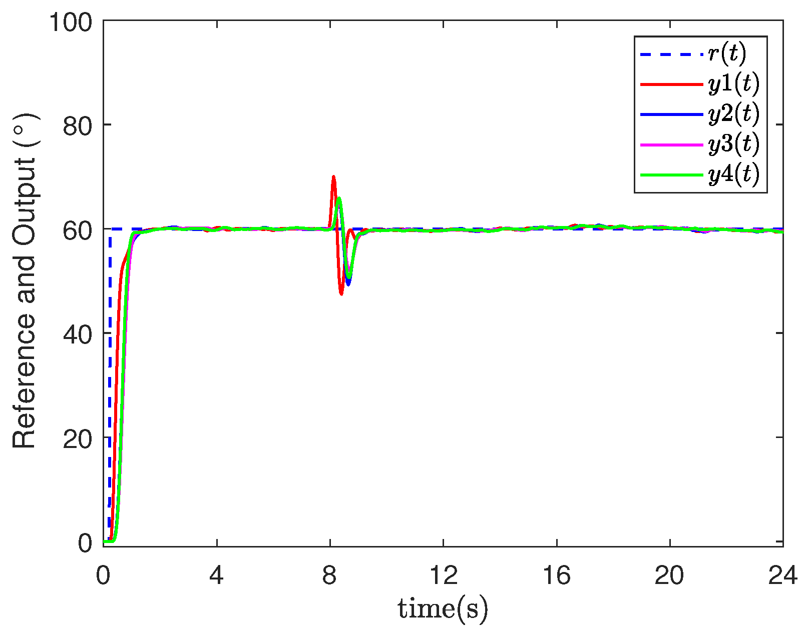
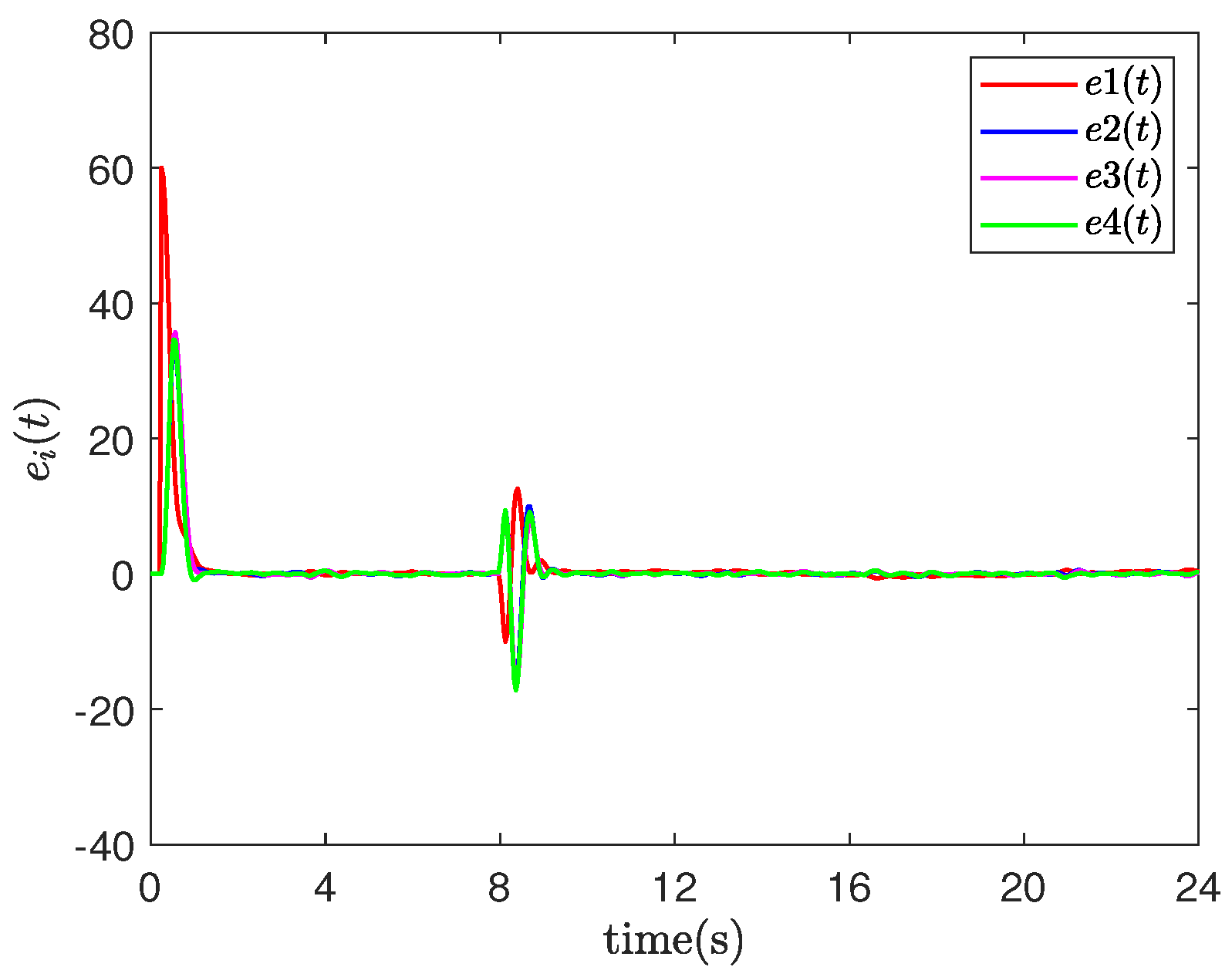
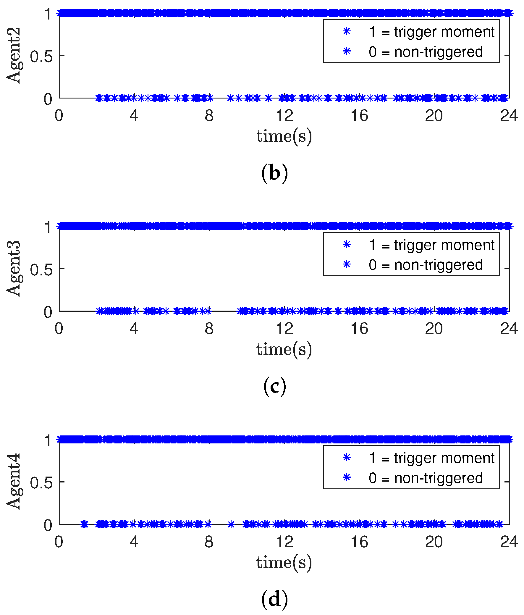
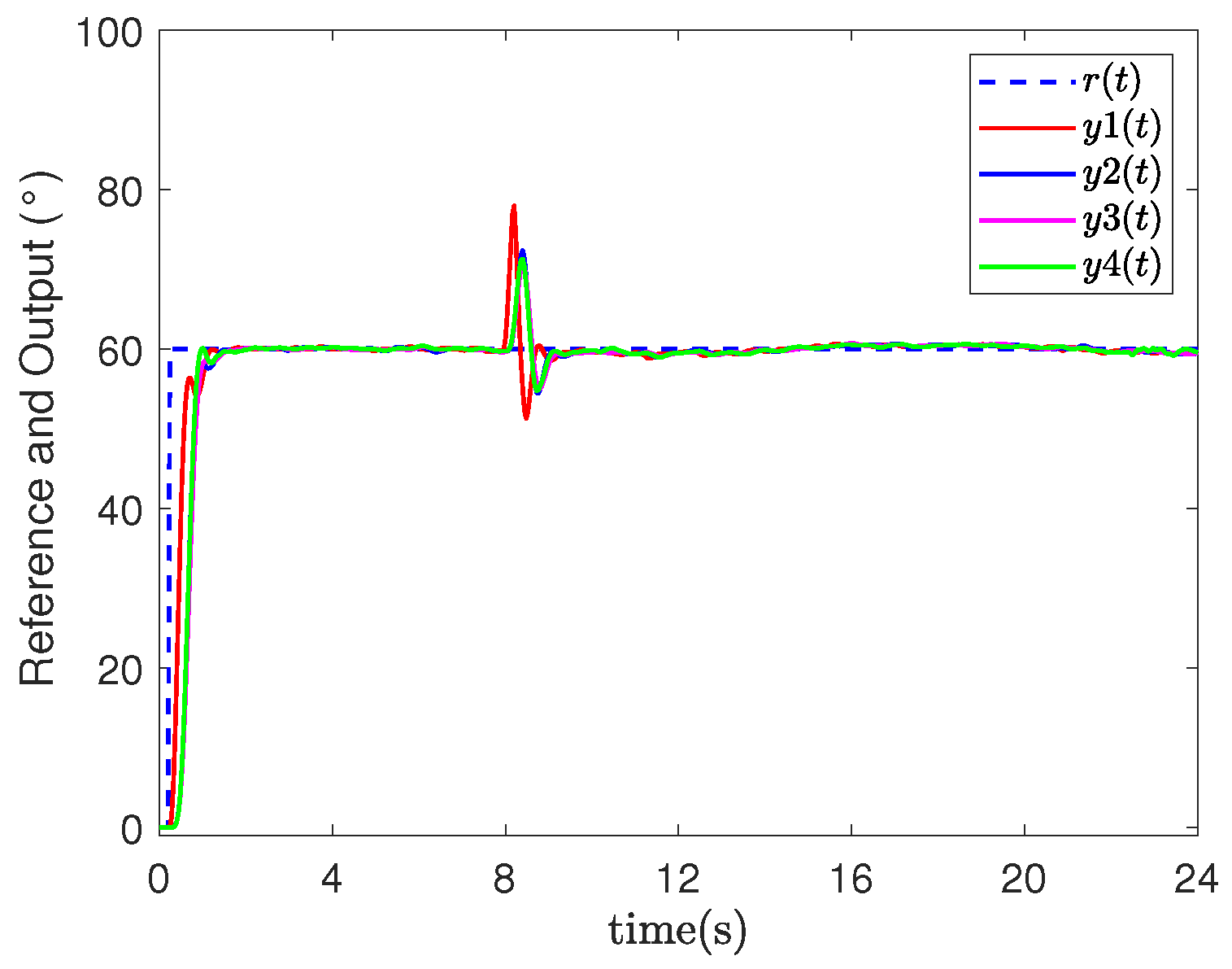
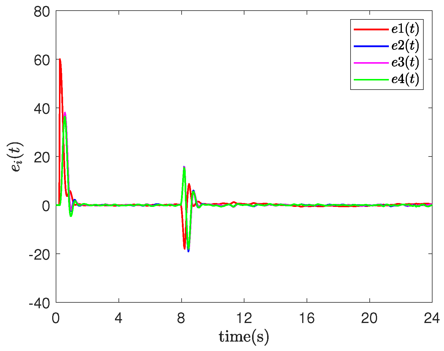
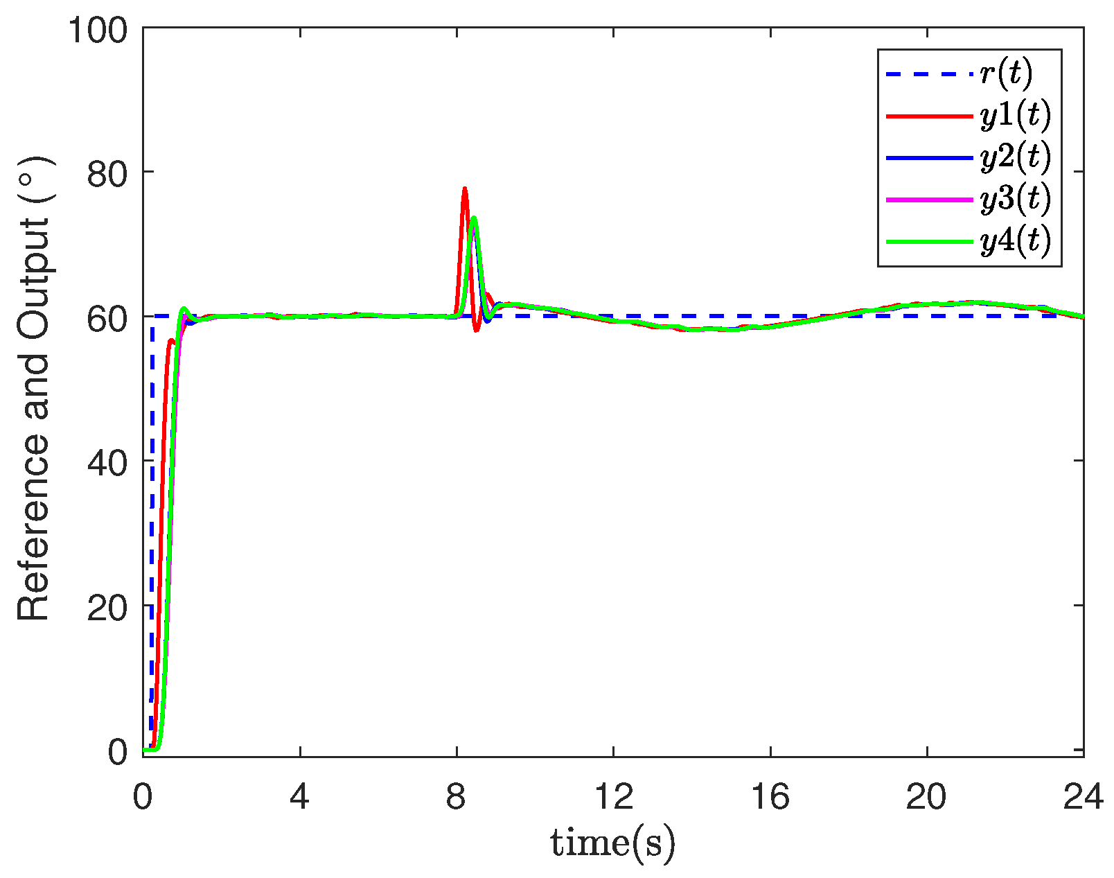
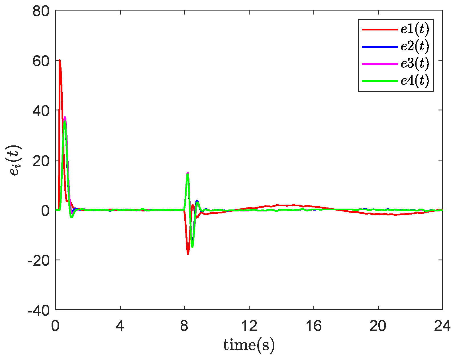
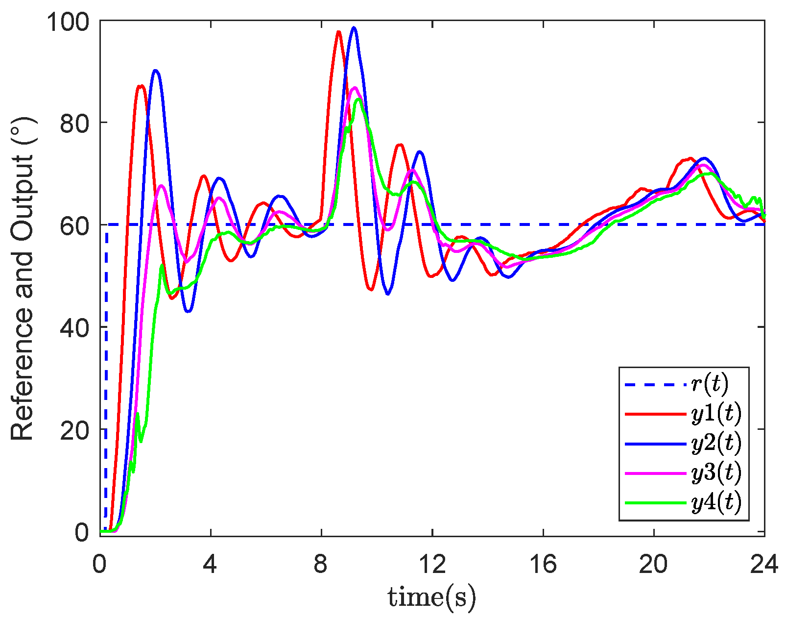
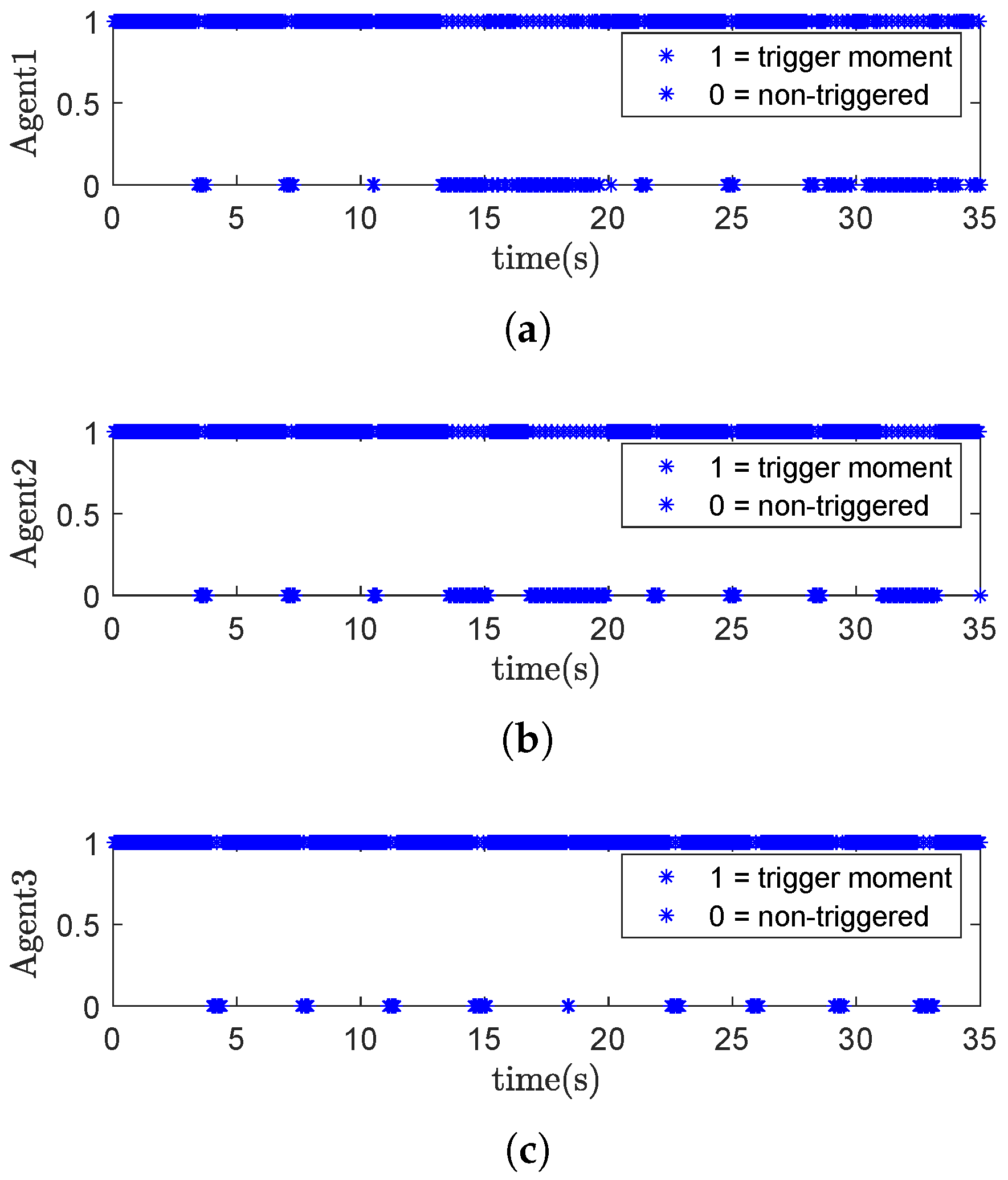
Event-triggered networked predictive fault-tolerant control (ENPFTC): When agent 1 encounters an actuator fault at 8 s, after compensation by the controller, the system output quickly returns to the vicinity of the reference value as shown in Figure 3, and the tracking error converges to near zero, while the maximum tracking error is less than 0.5 as shown in Figure 4, indicating that the designed fault-tolerant control method can actively compensate for actuator faults. When the system is stabilized, the event trigger effectively reduces the amount of data transmission in the feedback channel of the agent, the number of event triggers are 478/600, 483/600, 461/600 and 469/600, the statistics of event trigger counts show that the event trigger can reduce the data transmission volume by about 21 % , and the event trigger record is shown in Figure 5, where “1(0)” means that the event trigger is (not) triggered. In addition, we updated the actuator fault f 1 ( t ) to 1.2 sin ( 0.02 ( t 200 ) ) + 0.4 when t 200 , and repeated the simulation. The output result and tracking errors of ENPFTC are shown in Figure 6 and Figure 7, respectively.
(2)
Event-triggered networked predictive control (ENPC): This scheme only compensates for random communication constraints without active fault-tolerant control. As shown in Figure 8, once an actuator fault occurs, the system output fails to maintain a stable state near the reference value. This results in a large tracking error, with the deviation exceeding 1 for an extended period, as illustrated in Figure 9.
(3)
Event-triggered fault-tolerant control (EFTC): This scheme does not compensate for the random communication constraints of the system. As shown in Figure 10, the system output is quite bad compared to the previous two methods, while the tracking error has a deviation value exceeding 10 for most of the time, as shown in Figure 11.
In addition, the second numerical simulation is carried out using a networked multi-agent system in [9] to further verify the effectiveness of the proposed control method, and the communication topology G of the control scheme is shown in Figure 12.
The specific experimental parameters are set as follows:
a 21 = a 32 = 1 ,
a 13 = a 31 = a 12 = a 23 = 0 ,
W 1 = W 2 = W 3 = 5 ,
N 1 = N 2 = N 3 = I ,
η 1 = η 2 = η 3 = 0.125 10 3 ,
τ t , 1 ca [ 2 5 ] , τ t , 2 ca [ 3 5 ] , τ t , 3 ca [ 2 4 ] ,
τ t , 1 sc [ 4 6 ] , τ t , 2 sc [ 3 7 ] , τ t , 3 sc [ 3 8 ] .
The system sampling frequency is 0.05 s, and the desired relative positions are set as follows:
δ p 1 ( t ) = 0 4 + sin ( t ) 8 T δ p 2 ( t ) = 3 ( 4 + sin ( t ) ) / 2 ( 4 + sin ( t ) ) / 2 8 T δ p 3 ( t ) = 3 ( 4 + sin ( t ) ) / 2 ( 4 + sin ( t ) ) / 2 8 T .
At 20 s, the actuator fault applied to the agent 1 is as follows:
f 1 ( t ) = 0 , t < 400 4 , t 400 .
(1)
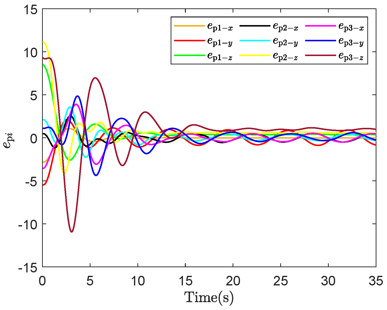
ENPFTC: As shown in Figure 13, the system tends to stabilize after running for a period of time. At 20 s, agent 1 experiences an actuator fault, and the output shows fluctuations. Due to the compensation action of the proposed controller, the tracking error converges to the neighborhood of zero, while the maximum tracking error is less than 0.2 , indicating that the designed fault-tolerant control method can actively compensate for actuator faults. In Figure 14, the number of event triggers are 516/700, 548/700 and 634/700, respectively, which show that the event trigger can reduce the data transmission volume by about 19 % .
(2)
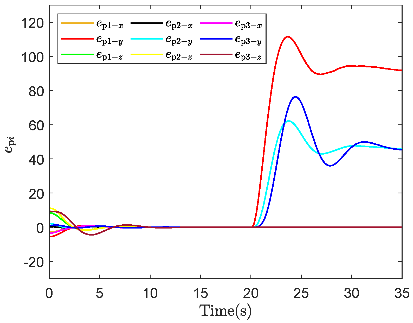
ENPC: As no fault handling measures are implemented, it can be observed from Figure 15 that the tracking error exceeded 40 after the occurrence of the fault.
(3)
EFTC: As can be observed in Figure 16, due to the influence of random communication constraints, the tracking error continues to oscillate persistently, failing to meet the required control performance.
(4)
Discussion: ENPC does not consider the impact of actuator faults on the system, while the EFTC method does not take network delay into account. Although both methods have relatively low controller computation loads, they exhibit poor tracking control performance. The ENPFTC method comprehensively considers the system’s data transmission volume, actuator faults, and random network delays. It can reduce data transmission volume by more than 19%, effectively conserving network resources, and achieves better tracking control performance. However, this comes at the cost of increased computational load on the controller. In addition, a performance metric i = 1 N t = 0 600 e i ( t ) 2 2 is defined to quantitatively analyze and compare the system’s tracking control performance. The corresponding values for Figure 4, Figure 9, and Figure 11 are 44,982.44, 48,001.29, and 433,741.75, respectively. In the second numerical simulation, the corresponding values of the performance metric i = 1 N t = 0 700 e p i ( t ) 2 2 of Figure 13, Figure 15, and Figure 16 are 2212.59 , 2,457,205.70 and 2533.19, respectively. These results demonstrate that the ENPFTC method proposed in this paper has better tracking control performance compared to the other two methods. Future work will consider offloading the controller to a cloud-based environment to reduce the local computational burden.

5. Conclusions

This paper has presented an innovative event-triggered networked predictive fault-tolerant control scheme for NMASs, designed to operate under the complex conditions of random communication constraints in both forward and feedback channels, as well as actuator faults. Comprehensive numerical simulations comparing the ENPC, EFTC, and ENPFTC methods clearly demonstrate the effectiveness of the proposed control scheme. The results show that the scheme successfully compensates for actuator faults and mitigates the impact of random communication constraints. Furthermore, the proposed event-triggered mechanism reduces data transmission volume by more than 19%. Future research could focus on developing adaptive and robust control strategies that can handle model uncertainties and further reduce the impact of event-triggered delays.

Author Contributions

Conceptualization, C.L. and P.L.; methodology, C.L.; software, P.L. and Z.D.; validation, C.L., P.L., and H.G.; formal analysis, C.-B.Z.; investigation, H.G.; resources, C.L.; data curation, P.L.; writing—original draft preparation, C.L.; writing—review and editing, C.-B.Z. and Z.D.; visualization, P.L.; supervision, C.L.; project administration, C.L.; funding acquisition, H.G. All authors have read and agreed to the published version of the manuscript.

Funding

This research was funded by the National Natural Science Foundation of China under Grant 62173002 and 62441304, the National Key R&D Program of China under Grant 2023YFC3306401, the Beijing Natural Science Foundation under Grant 4222045, the Natural Science Foundation of Henan Province under Grant 252300421506, the Key Scientific Research Projects of Henan Province’s Institutions of Higher Education under Grant 24A120001 and 25A120008, and the Scientific Problem Tackling of Henan Province under Grant 252102320053.

Institutional Review Board Statement

Ethical approval is not required for this study as it do not involve human participants.

Informed Consent Statement

Written informed consent is obtained from all participants involved in this study.

Data Availability Statement

All data supporting the findings of this study are included within the article.

Conflicts of Interest

The authors declare no conflicts of interest.

References

  1. Shen, H.; Wen, G.; Lv, Y. Collaborative parameter estimation of multiple unmanned surface vessels: A robust distributed estimator-based approach. IEEE Trans. Ind. Inf. 2024, 20, 1294–1303. [Google Scholar] [CrossRef]
  2. Pang, Z.-H.; Mu, T.; Yu, Y.; Guo, H.; Liu, G.-P.; Han, Q.-L. Networked predictive control: A survey. IEEE/CAA J. Autom. Sin. 2025; early access. [Google Scholar]
  3. Zheng, C.-B.; Pang, Z.-H.; Wang, J.-X.; Sun, J.; Liu, G.-P.; Han, Q.-L. Null-space-based time-varying formation control of uncertain nonlinear second-order multi-agent systems with collision avoidance. IEEE Trans. Ind. Electron. 2023, 70, 10476–10485. [Google Scholar] [CrossRef]
  4. Pang, Z.-H.; Liu, G.-P.; Zhou, D.; Chen, M. Output tracking control for networked systems: A model-based prediction approach. IEEE Trans. Ind. Electron. 2014, 61, 4867–4877. [Google Scholar] [CrossRef]
  5. Pang, Z.-H.; Du, T.; Gao, S.; Han, Q.-L.; Liu, G.-P. Cooperative tracking control of networked multi-agent systems: A dual-prediction plus correction approach. IEEE Trans. Ind. Inf. 2025, 21, 146–155. [Google Scholar] [CrossRef]
  6. Pang, Z.-H.; Luo, W.-C.; Liu, G.-P.; Han, Q.-L. Observer-based incremental predictive control of networked multi-agent systems with random delays and packet dropouts. IEEE Trans. Circuits Syst. II Express Briefs 2021, 68, 426–430. [Google Scholar] [CrossRef]
  7. Li, T.; Zhang, W.; Yu, L. Improved switched system approach to networked control systems with time-varying delays. IEEE Trans. Control Syst. Technol. 2019, 27, 2711–2717. [Google Scholar] [CrossRef]
  8. Li, L.; Yao, L. Fault tolerant control of fuzzy stochastic distribution systems with packet dropout and time delay. IEEE Trans. Autom. Sci. Eng. 2024, 21, 2638–2647. [Google Scholar] [CrossRef]
  9. Pang, Z.-H.; Zheng, C.-B.; Li, C.; Liu, G.-P.; Han, Q.-L. Cloud-based time-varying formation predictive control of multi-agent systems with random communication constraints and quantized signals. IEEE Trans. Circuits Syst. II Express Briefs 2022, 69, 1282–1286. [Google Scholar] [CrossRef]
  10. Zhu, Z.; Yin, Y.; Wang, F.; Liu, Z.; Chen, Z. Practical robust fixed-time containment control for multi-agent systems under actuator faults. Expert Syst. Appl. 2024, 245, 123152. [Google Scholar] [CrossRef]
  11. Ma, Y.; Jiang, B.; Wang, J.; Gong, J. Adaptive fault-tolerant formation control for heterogeneous UAVs-UGVs systems with multiple actuator faults. IEEE Trans. Aerosp. Electron. Syst. 2023, 59, 6705–6716. [Google Scholar] [CrossRef]
  12. Du, D.; Li, Z. Passive fault-tolerant control for discrete parameter system. IET Power Electron. 2023, 16, 1969–1983. [Google Scholar] [CrossRef]
  13. Shi, J.; Chen, X.; Xing, S.; Liu, A.; Chen, C. Robust cooperative fault-tolerant control for uncertain multi-agent systems subject to actuator faults. Sensors 2024, 24, 2651. [Google Scholar] [CrossRef] [PubMed]
  14. Li, H.; Zhang, N.; Wu, G.; Li, Z.; Ding, H.; Jiang, C. Active fault-tolerant control of a four-wheel independent steering system based on the multi-agent approach. Electronics 2024, 13, 748. [Google Scholar] [CrossRef]
  15. Feng, Z.; Hu, G. Connectivity-preserving flocking for networked Lagrange systems with time-varying actuator faults. Automatica 2019, 109, 108509. [Google Scholar] [CrossRef]
  16. Rahimi, F.; Esfanjani, R. Estimating tolerable communication delays for distributed optimization problems in control of heterogeneous multi-agent systems. IET Control Theory Appl. 2024, 18, 626–639. [Google Scholar] [CrossRef]
  17. Li, S.; Chen, Y.; Liu, X. Fault estimation and fault-tolerant tracking control for multi-agent systems with lipschitz nonlinearities using double periodic event-triggered mechanism. IEEE Trans. Signal Inf. Process. Networks 2023, 9, 229–241. [Google Scholar] [CrossRef]
  18. Xu, N.; Chen, Z.; Niu, B.; Zhao, X. Event-triggered distributed consensus tracking for nonlinear multi-agent systems: A minimal approximation approach. IEEE J. Emerging Sel. Top. Circuits Syst. 2023, 13, 767–779. [Google Scholar] [CrossRef]
  19. Wang, Y.; Yang, Y.; Wu, L. Adaptive fault-tolerant consensus control of multi-agent systems with event-triggered inputs. Inf. Sci. 2023, 650, 119594. [Google Scholar] [CrossRef]
  20. Wang, J.; Zheng, Y.; Deng, J.; Zhang, H.; Sun, J. Memory-based event-triggered fault-tolerant consensus control of nonlinear multi-agent systems and its applications. IEEE Trans. Autom. Sci. Eng. 2025, 22, 7941–7954. [Google Scholar] [CrossRef]
  21. Li, C.; Wang, S.; Pang, Z.; Zheng, C.; Sun, D.; Xu, S. Active fault-tolerant predictive control for networked multi-agent systems with actuator faults and random communication constraints. In Proceedings of the 2023 IEEE 12th Data Driven Control and Learning Systems Conference (DDCLS), Xiangtan, China, 12–14 May 2023; pp. 1859–1864. [Google Scholar]
  22. Pang, Z.-H.; Liu, G.-P.; Zhou, D.; Hou, F.; Sun, D. Two-channel false data injection attacks against output tracking control of networked systems. IEEE Trans. Ind. Electron. 2016, 63, 3242–3251. [Google Scholar] [CrossRef]
Figure 1. ENPFTC scheme.
Applsci 15 06317 g001
Figure 2. Communication topology G .
Applsci 15 06317 g002
Figure 3. Output result of ENPFTC.
Applsci 15 06317 g003
Figure 4. Tracking errors of ENPFTC.
Applsci 15 06317 g004
Figure 5. Event trigger moments of agents. (a) Event trigger moment of agent 1. (b) Event trigger moment of agent 2. (c) Event trigger moment of agent 3. (d) Event trigger moment of agent 4.
Applsci 15 06317 g005aApplsci 15 06317 g005b
Figure 6. Output result of ENPFTC when the fault amplitude is 1.6.
Applsci 15 06317 g006
Figure 7. Tracking errors of ENPFTC when the fault amplitude is 1.6.
Applsci 15 06317 g007
Figure 8. Output result of ENPC.
Applsci 15 06317 g008
Figure 9. Tracking errors of ENPC.
Applsci 15 06317 g009
Figure 10. Output result of EFTC.
Applsci 15 06317 g010
Figure 11. Tracking errors of EFTC.
Applsci 15 06317 g011
Figure 12. Communication topology G .
Applsci 15 06317 g012
Figure 13. Tracking errors of ENPFTC.
Applsci 15 06317 g013
Figure 14. Event trigger moments of agents. (a) Event trigger moment of agent 1. (b) Event trigger moment of agent 2. (c) Event trigger moment of agent 3.
Applsci 15 06317 g014
Figure 15. Tracking errors of ENPC.
Applsci 15 06317 g015
Figure 16. Tracking errors of EFTC.
Applsci 15 06317 g016
Disclaimer/Publisher’s Note: The statements, opinions and data contained in all publications are solely those of the individual author(s) and contributor(s) and not of MDPI and/or the editor(s). MDPI and/or the editor(s) disclaim responsibility for any injury to people or property resulting from any ideas, methods, instructions or products referred to in the content.

