Article

Displacement Patterns and Predictive Modeling of Slopes in the Bayan Obo Open-Pit Iron Mine

School of Resources and Civil Engineering, Northeastern University, Shenyang 110819, China
*
Author to whom correspondence should be addressed.
Appl. Sci. 2025, 15(11), 6068; https://doi.org/10.3390/app15116068
Submission received: 23 April 2025 / Revised: 21 May 2025 / Accepted: 26 May 2025 / Published: 28 May 2025
(This article belongs to the Special Issue Novel Technology in Landslide Monitoring and Risk Assessment)

Abstract

To address the limitations of traditional early warning methods in open-pit slope displacement monitoring—particularly their neglect of spatiotemporal correlations and their difficulty in analyzing multi-scale non-stationary sequences—this study proposes an early warning framework that integrates spatiotemporal clustering with multi-scale decomposition. Taking the southern slope of the Bayan Obo Main Pit as a case study, high-risk deformation zones were identified using DBSCAN-based spatiotemporal clustering applied to slope radar monitoring data. The displacement time series were decomposed using Variational Mode Decomposition (VMD) into trend and periodic components, for which Gated Recurrent Unit (GRU) and Long Short-Term Memory (LSTM) models were respectively developed. The results indicate that (1) DBSCAN effectively detects clusters characterized by high average cumulative displacement and broad spatial distribution, while filtering out isolated outliers. (2) The trend component prediction achieved a coefficient of determination (R2) of 0.99755, while the periodic component prediction yielded a root mean square error (RMSE) of just 0.0978 mm. The reconstructed total displacement achieved an R2 of 0.9973, verifying the proposed multi-scale decomposition and hybrid modeling framework’s high accuracy and robustness in slope deformation modeling and early warning.

1. Introduction

From the 1990s to the early 21st century, with the continuous exploitation and utilization of resources, deep concave open-pit mines have become a development trend for open-pit mining worldwide [1]. Because of the lack of effective landslide early warning methods, it is often impossible to issue timely warnings before landslides occur, resulting in severe casualties and economic losses, which seriously affect mine production and people’s daily lives. Traditional monitoring technologies—such as GNSS [2], 3D laser scanning [3], and total stations [4]—are limited by their single-point data acquisition modes [5,6] and delayed data processing mechanisms [7,8,9], making it difficult to fully capture the spatiotemporal evolution characteristics of slope deformation.
In recent years, slope radar has emerged as an important technical means for identifying, determining, and predicting landslide deformation fields because of its advantages of high-precision measurement, large-scale monitoring capability, and all-weather microwave remote sensing technology [10,11,12]. Existing early warning models primarily emphasize the temporal variation in displacement [13] while neglecting spatial correlations between monitoring points. In practical engineering applications, this often leads to insufficient accuracy in identifying deformation zones and an inability to accurately reflect the spatial distribution of slope deformation. Moreover, current methods lack consideration of the detailed evolution characteristics of displacement, making it easy to misinterpret isolated outliers caused by local disturbances or equipment errors as deformation signals. Such misjudgments not only increase the false alarm rate but may also obscure actual deformation trends, thereby undermining the reliability of early warning results. Therefore, to address this issue, this study employs the Density-Based Spatial Clustering of Applications with Noise (DBSCAN) algorithm to identify and select clusters of monitoring points with significant displacement and a certain degree of spatial distribution as early warning units.
The analysis of displacement curves within early warning units is complicated by the significantly non-stationary nature of slope displacement sequences, which results from the coupling of topographic, structural, and hydrogeological factors. Their evolution involves two key dynamic mechanisms: (1) long-term trend deformation dominated by geological structural stress, representing the long-term evolution of time-dependent damage accumulation in the rock mass, and (2) quasi-periodic responses induced by cyclical environmental disturbances (such as rainfall infiltration), reflecting the recurring effects of seasonal hydrological cycles. This multi-scale coupling feature poses fundamental challenges to traditional single-model prediction approaches: when a single model is used to directly fit the original displacement sequence, high-frequency noise can mask the underlying trend, while low-frequency trends may interfere with the extraction of periodic features, ultimately limiting the generalization capability of the predictive model. To address this issue, some researchers have proposed a “decomposition–prediction–reconstruction” framework, in which landslide displacement is first decomposed into different components, separate models are constructed for each component, and the results are finally reconstructed by summation to improve both prediction accuracy and model adaptability.
In the decomposition of displacement, traditional methods typically use wavelet analysis, empirical mode decomposition (EMD), and ensemble empirical mode decomposition (EEMD). For example, Li et al. [14] introduced wavelet analysis in their study of surface subsidence pattern recognition in underground metal mining areas. They analyzed the frequency variations in SBAS-InSAR-derived subsidence time series, identifying low-frequency signals to locate zones of stable subsidence and using high-frequency components to capture the frequency and amplitude of sudden deformation events. Zhou et al. [15] applied wavelet analysis to decompose landslide displacement series into components with distinct frequency characteristics, based on an analysis of the chaotic nature of the displacement time series. Huang et al. [16] investigated the displacement sequence at monitoring point D3 of the Baijiabao landslide, decomposing the original displacement series into low-, medium-, and high-frequency components using wavelet transform; the lowest frequency term was treated as the trend component, while the sum of the remaining terms represented the periodic component. Xu et al. [17] adopted empirical mode decomposition (EMD) to divide cumulative displacement into trend and periodic components, successfully extracting rainfall-related intrinsic mode functions (IMFs), which improved the performance of subsequent Long Short-Term Memory (LSTM)-based prediction. Zhang et al. [18] proposed a soft-sifting-criterion-optimized EMD approach, integrating K-means clustering and an FOA-LSSVM model to effectively predict “step-like” landslide displacements. While the model enhanced both the interpretability and accuracy of prediction, the method required complex parameter optimization. Yuan et al. [19] focused on the deformation characteristics of step-like landslides and used EMD to separately decompose multi-point monitoring data into trend and periodic components. To address the non-stationarity of displacement data, Liu et al. [20] employed ensemble empirical mode decomposition (EEMD) and embedded the decomposed features into a Convolutional Neural Network (CNN)–LSTM hybrid model, significantly boosting prediction accuracy. Kang et al. [21] utilized EEMD to reconstruct displacement series into physically interpretable trend and fluctuation components for spoil slopes with nonlinear and small-sample characteristics, thereby improving prediction robustness. Deng et al. [22] applied EEMD to decompose the surface displacement time series of the Baishuihe landslide into trend and fluctuation components, further illustrating the effectiveness of the method. Although these methods have achieved certain successes, they also exhibit notable shortcomings: for example, wavelet analysis relies on the empirical selection of basis functions, which limits its ability to capture the non-stationary characteristics of slope displacement and may result in energy leakage. EMD employs an adaptive decomposition approach that overcomes the dependency on predefined basis functions, but it still suffers from severe mode mixing and end effects, which can distort the decomposition results. EEMD introduces white noise and performs ensemble averaging to effectively mitigate mode mixing, yet it incurs high computational costs, and residual noise may still interfere with the accuracy of low-frequency components. Therefore, to address the limitations of the existing methods, after identifying early warning units using the DBSCAN algorithm, this study adopts Variational Mode Decomposition (VMD) [23] to decompose the landslide displacement within these units into trend and periodic components with clear physical interpretations [24]. Compared to traditional methods, such as wavelet analysis, EMD, and EEMD, VMD offers superior adaptability and frequency-domain constraints, effectively mitigating mode mixing while ensuring stable and controllable decomposition outcomes—making it well suited for handling non-stationary and nonlinear slope displacement data.
In terms of prediction models, traditional machine learning methods have been widely used. Li et al. [25] proposed a dynamic interval prediction method for landslide displacement based on the random forest algorithm, which enhanced prediction accuracy and reliability by automatically identifying deformation states and incorporating a state-transition model. Senanayake et al. [26] developed a regression-based machine learning approach using 3D photogrammetric models of open-pit highwalls to rapidly predict rockfall energy and run-out distances. Zhang et al. [27] applied ensemble learning techniques (RF and XGBoost) to slope stability prediction, achieving higher accuracy compared to support vector machines and logistic regression. Kardani et al. [28] employed a hybrid stacking ensemble method optimized by the artificial bee colony (ABC) algorithm, integrating finite element-derived synthetic data with 107 field cases, and achieved a prediction AUC of 90.4%, significantly outperforming single machine learning models (maximum AUC 82.9%) and basic ensemble methods. However, traditional machine learning models remain essentially static, suffering from limited modeling capacity, an inability to capture temporal dependencies, and high computational complexity.
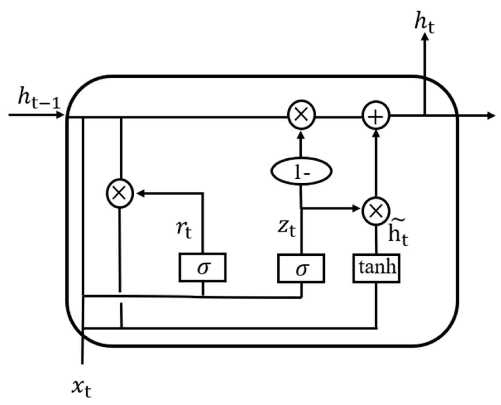
With the rapid advancement of deep learning technologies, LSTM and Gated Recurrent Unit (GRU) models have overcome the gradient vanishing and explosion problems associated with recurrent neural networks (RNNs). These models, which process data sequentially over time, are well suited for time series prediction tasks and have seen widespread application in various fields in recent years [29]. Xie et al. [30] employed LSTM to predict the periodic displacement of landslides, finding that LSTM exhibited excellent dynamic properties. Xing et al. [31] applied LSTM in displacement prediction for the Baishuihe landslide, demonstrating that LSTM outperformed the Extreme Learning Machine (ELM) in terms of prediction accuracy. Yang et al. [32] applied LSTM to landslide displacement analysis, revealing that compared to static models, LSTM better captured the dynamic characteristics of landslides and effectively utilized historical data. Zhang et al. [33] developed a landslide displacement prediction model using GRU and applied it to the Diaohuo landslide in the Three Gorges area, showing that GRU offered higher prediction accuracy than the Support Vector Machine (SVM). Zhang et al. [34] further applied GRU to predict displacement at the Jiuxianping landslide, demonstrating its superior performance in capturing dynamic displacement features and providing a more accurate representation of the Jiuxianping landslide’s deformation, with fewer outliers compared to static models. Inspired by previous studies, this research applies both LSTM and GRU models to displacement prediction and further introduces representative models, such as Temporal Convolutional Network (TCN), RNN, and Autoregressive Integrated Moving Average (ARIMA), for comparative analysis, aiming to systematically evaluate the performance of different modeling approaches in capturing displacement patterns.
This study focuses on the south slope of the main pit in the Bayan Obo open-pit mine. After identifying early warning units using the DBSCAN algorithm, the landslide displacement data of these units are decomposed by VMD into trend and periodic components with clear physical significance. The GRU model is then used to predict the trend component, while the LSTM model is applied to the periodic component. The final displacement prediction is obtained through weighted reconstruction to improve overall accuracy.
Accordingly, the objective of this study is to address the high rates of false and missed alarms by fully considering the spatiotemporal distribution characteristics of slope deformation. A displacement prediction framework is established to improve forecasting accuracy and to assign explicit physical meanings to the decomposed components. This work provides a novel solution to critical challenges in open-pit slope monitoring, particularly the inadequate consideration of spatiotemporal correlations and the difficulty in modeling multi-scale non-stationary sequences in conventional early warning systems.

2. Data and Methodology

2.1. Study Area and Engineering Background

The Bayan Obo Main Pit is located in central Inner Mongolia, 106 km south of the Mongolian People’s Republic and 149 km north of Baotou City. It covers a total area of 48 square kilometers, with the current slope height exceeding 200 m. The southern slope of the main pit features well-developed joint fissures and fault structures and contains a large amount of water-sensitive minerals such as mica and montmorillonite. These minerals remain relatively stable within the rock mass under dry conditions, but once exposed to water, they undergo disintegration and volume expansion. This results in additional tensile stress within the internal fissures of the rock mass, potentially leading to matrix dilatancy, joint opening, propagation, and interconnection—posing significant risks to the stability of the southern slope and threatening the safe mining operations at the Bayan Obo Iron Mine. The geological cross-section is shown in Figure 1.
Under the influence of intense rainfall, a major landslide occurred on the southern slope of the main pit on 29 August 2020. The location of the landslide is shown in Figure 2, situated between elevations 1626 m and 1570 m, with the collapsed material extending down to the 1458 m level. The sliding body had an approximate thickness of 40 m. As shown in the geological cross-section, the southern side of the main pit is primarily composed of north-dipping slate. The landslide was not only affected by fault zones but also mainly controlled by anti-dip structural planes. The landslide mode is identified as a toppling and fracturing failure induced by the combined effects of fault fracture zones and structural planes. The rear of the sliding mass was controlled by the dip-aligned F17 fault fracture zone, while the front was primarily affected by the F18 fault fracture zone. The anti-dip structural planes within the rock mass are the key factors causing the toppling-type failure of the landslide [35,36].
A ground-based synthetic aperture radar (GB-SAR) was deployed on the northern slope of the main pit. Monitoring was conducted by aligning differential interferometry measurements with point cloud models obtained via drone photogrammetry. Displacement cloud maps of the landslide area at different time intervals during the failure process are shown in Figure 3. The maps reveal that as time progressed, the displacement within the landslide zone continuously increased, which corresponds well with the actual landslide behavior.

2.2. Data

Radar monitoring data are stored in the cloud database in the form of point clouds. By selecting a date and querying via the web interface, the corresponding radar point cloud data are retrieved from the database, rendered into images, and projected onto a 3D model.
Using the 2020 landslide event on the southern slope of the Bayan Obo Iron Mine’s main pit as an example, a total of 114,283 radar displacement monitoring points were extracted. Each data point includes spatial coordinates ( X i , Y i , Z i ) and a time series of pre-landslide displacement values. The displacement time series is recorded hourly from 00:00 on 27 August to 00:00 on 29 August 2020, resulting in an initial dataset with 3 spatial dimensions and 48 temporal dimensions.
To meet DBSCAN’s density uniformity assumption and prevent regions with large displacement values from dominating the clustering result, the displacement data were standardized using Equation (1). The StandardScaler was applied to ensure all displacement variables have a mean of 0 and a variance of 1, eliminating the effect of differing data scales:
x s t d = x μ σ
where x s t d is the standardized displacement, μ is the mean, and σ is the standard deviation.
To eliminate unit differences among coordinate axes and avoid unequal weightings in distance calculations, the spatial coordinates were normalized using Equation (2):
x n o r m = z x x m i n x m a x x m i n
where x n o r m is the normalized spatial data, z is the scaling factor, x is the original spatial data from the time series, and x m a x and x m i n are the maximum and minimum values, respectively.
After clustering the radar data, early warning units were identified. Subsequently, the selected time series were decomposed using VMD. Each decomposed component was then used as input for the GRU and LSTM models. Prior to model training, the data used for each model were preprocessed accordingly. For the GRU model, the dataset was divided into training and test sets in an 8:2 ratio. After partitioning, the input data were normalized using Equation (3):
x n o r m = x min x max x min x
where m i n ( x ) and max x are the minimum and maximum values of the data, respectively.
For the LSTM model, 70% of the data was used as the training set and 30% as the test set, conforming to conventional practices in time series forecasting. After partitioning, the current rainfall (from 27 August 00:00 to 29 August 00:00) and the prior two-day rainfall (from 25 August 00:00 to 26 August 23:59) were introduced as influencing factors. The VMD-decomposed periodic displacement component and the rainfall data were standardized using Equation (1) to enhance the stability of LSTM training. The data were then reshaped into the format (time steps × features × dimensions × samples) to satisfy the input requirements of the LSTM model in MATLAB R2022a.

2.3. Methodology

2.3.1. Identification of Early Warning Units Based on the Clustering Algorithm

DBSCAN (Density-Based Spatial Clustering of Applications with Noise) is a density-based spatial clustering algorithm. Its core idea is to identify clusters with similar characteristics based on the spatial density of data points while effectively distinguishing noise points. The algorithm defines two key parameters—the neighborhood radius ε (Eps) and the minimum number of points in the neighborhood (MinPts)—to describe the density level of data distribution.
Given a dataset D, for any data point p, its ε-neighborhood is defined as follows (Equation (4)):
N ε p = q D d i s t p , q ϵ
where dist(p , q) is the distance between points p and q, typically measured by Euclidean distance (Equation (5)):
d i s t p , q = i = 1 n ( p i q i ) 2
Based on the number of points within the ε-neighborhood, DBSCAN classifies data points into three categories:
Core Point: If the ε-neighborhood of a point p contains at least MinPts points, as described in Equation (6)
N ε p M i n P t s
then p is a core point.
Border Point: A border point is a point that is not itself a core point but lies within the ε-neighborhood of a core point.
Noise Point: A point that is neither a core point nor a border point is considered a noise point.
The DBSCAN clustering process is based on the connectivity of core points. Specifically, if two core points have overlapping ε-neighborhoods, they belong to the same cluster. The algorithm recursively merges all core points and their neighborhood points to form a complete cluster. Border points belong to a core point’s cluster but do not contribute to further expansion. Noise points are not included in any cluster.
In implementation, DBSCAN randomly selects an unvisited point as a starting point and checks if it is a core point. If so, it begins expanding from that point to form a new cluster. The expansion involves adding all core points in the ε-neighborhood and their neighbors to the cluster, continuing until no more points can be added. Then, a new core point is selected from the remaining unvisited points, and the process is repeated until all points are labeled as part of a cluster or as noise.
DBSCAN is advantageous in identifying clusters of arbitrary shapes and does not require prior specification of the number of clusters. Compared with algorithms like K-means, DBSCAN is more suitable for complex data distributions. However, it also has limitations, such as sensitivity to the choice of ε and MinPts, and the risk of the “curse of dimensionality” when dealing with high-dimensional data. To address this, dimensionality reduction and parameter optimization were performed during data preprocessing.
In this study, Principal Component Analysis (PCA) was employed for dimensionality reduction. PCA is an unsupervised dimensionality reduction technique used for data compression, denoising, feature extraction, and visualization. PCA identifies the directions (principal components) that account for the most variance in the data and uses those as new feature axes.
The dimensionality reduction procedure involves combining the standardized displacement data and the normalized spatial coordinates into a mixed feature matrix as the input for PCA. The Scikit-learn PCA module uses Singular Value Decomposition (SVD) instead of the traditional covariance matrix, directly decomposing the standardized data into a left singular matrix, singular values, and a right singular matrix. The column vectors of the right singular matrix represent the principal directions, avoiding numerical instability from explicitly computing the covariance matrix.
The top 20 principal components, accounting for a cumulative variance contribution of over 92.2%, were selected (Figure 4). This shows that most of the information is preserved with minimal loss.
Using the PCA-reduced data, the 10th nearest neighbor distance for each point was calculated via K-Nearest Neighbors. These distances were sorted and plotted as a curve. By observing the “elbow” in the curve, a suitable range for ε could be intuitively estimated.
Candidate ε values were uniformly selected from the 50th to 99th percentiles of the sorted distances. The minimum number of samples MinPts was set between 30 and 90. For each parameter set, DBSCAN was run, and the resulting silhouette coefficient was calculated. The silhouette coefficient is defined as shown in Equation (7).
O i = w i u i m a x u i , w i
where u i and w i represent the similarity between data point P i and its current cluster and other clusters, respectively.
The silhouette coefficient measures the similarity of each point to other points within its own cluster and its dissimilarity to points in other clusters. Its value ranges from −1 to 1. The parameter selection is based on maximizing the overall silhouette coefficient. After parameter optimization, the clustering performance under different combinations of eps and MinPts was visualized using the silhouette coefficient heatmap, which helped verify the rationality of the parameter selection and marked the optimal parameter combination. Figure 5 and Figure 6 show the K-distance graph and the silhouette coefficient heatmap. As shown in the figures, when eps is set to 3.94 and MinPts is set to 70, the silhouette coefficient approaches 1, indicating a better clustering performance.

2.3.2. The Decomposition Principle and Process of PSO-VMD

Particle Swarm Optimization (PSO) [37] is a swarm intelligence-based optimization algorithm proposed by Kennedy and Eberhart in 1995, inspired by bird flock foraging and fish swarm predation behaviors. PSO seeks optimal solutions by simulating information sharing and collaboration among individuals (particles). It features simplicity, ease of implementation, and fast convergence, making it widely applicable to optimization problems such as parameter optimization, neural network training, and path planning.
The basic principle involves randomly generating a particle swarm, with each particle’s initial position x i and velocity v i randomly initialized. Each particle records its individual best position p b e s t i (the best position in the history of the particle) and the global best position g b e s t i (the best position in the history of the entire swarm). The individual best and global best are updated using the following velocity update Equation (8) and position update Equation (9):
v t + 1 i = ω · v t i + c 1 · r 1 · p b e s t i x t i + c 2 · r 2 · g b e s t x t i
where ω is the inertia weight, balancing global convergence and convergence speed; c 1 and c 2 are individual and social learning factors, respectively; and r 1 and r 2 are random numbers in [0, 1] to enhance exploratory randomness.
x t + 1 i = x t i + v t + 1 i
If the current fitness value surpasses the individual best, p b e s t i = x t + 1 i is updated. If a particle’s fitness exceeds the global best, g b e s t is updated. These steps are repeated until the termination criteria (fitness convergence) are met.
VMD is an adaptive signal decomposition method. Its core idea is to decompose raw signals into multiple Intrinsic Mode Functions (IMFs) with specific central frequencies by constructing a variational optimization problem. Unlike heuristic methods, such as EMD, VMD employs a rigorous mathematical framework solved iteratively via the Alternating Direction Method of Multipliers (ADMM).
Assuming a signal f(t) can be decomposed into K modes u k ( t ) , each with a central frequency ωk, VMD aims to minimize the total bandwidth of all modes while ensuring their sum equals the original signal. The constrained variational problem is formulated as (Equation (10)):
m i n u k , ω k k = 1 K t [ ( δ t + j π t ) u k ( t ) ] e j ω k t 2 2 s . t .   k = 1 K u k t = f t
where u k are mode components, f is the original signal, t is the time window, δ t is the Dirac function, ω k values are central frequencies, e j ω k t represents the estimated central frequency of analytic signals, k is the number of modes, j is the imaginary unit, and denotes convolution.
By introducing a quadratic penalty term α and Lagrange multiplier λ(t), the constrained problem is transformed into an unconstrained optimization (Equation (11)):
L u k , ω k , λ = α k = 1 K t [ ( δ t + j π t ) u k ] e j ω k t 2 2 + f t k = 1 K u k t 2 2 + λ t , f t k = 1 K u k t
The ADMM algorithm alternately updates u k , ω k , and λ until convergence. The update equations for u k and ω k are given in Equations (12) and (13):
u ^ n + 1 k ω = f ^ ω i k u ^ i ω + λ ^ ω 2 1 + 2 α ω ω k 2
ω k n + 1 = 0 ω u ^ n + 1 k ω 2 d ω 0 u ^ n + 1 k ω 2 d ω
where λ is the Lagrange multiplier, α is the bandwidth balancing parameter, and u ^ k ( ω ) , f ^ ω , and λ ^ ω are Fourier transforms of u k t , f ( t ) , and λ ( t ) , respectively.
Based on the above formulas, the original displacement data of the early warning unit was decomposed using VMD, allowing the total displacement to be separated into components with different physical meanings. Currently, the application of VMD faces the challenge that optimal parameter selection relies heavily on experience, and traditional trial-and-error methods are inefficient. The decomposition performance of VMD is significantly influenced by the choice of the penalty factor and the number of modes; improper selection may lead to overlapping or mixing of signals, thereby affecting prediction accuracy. Therefore, this study proposed using PSO to optimize the VMD parameters for improved decomposition performance.
The PSO-VMD workflow is illustrated in Figure 7.

2.3.3. GRU Model Construction

GRU is a deep learning-based time series modeling method. Through the hidden state transfer mechanism of recurrent neural networks, it dynamically captures trend features in non-stationary sequences. By coordinating the update gate and reset gate, it dynamically filters historical state information and reinforces memory retention. Its gating mechanism effectively captures cross-time-step dependencies in sequences. In this paper, GRU was used to predict the trend component curve, as it can effectively capture long-term trend features in sequences. Its basic principle can be found in Appendix A.
This paper constructed a GRU-based time series prediction model to capture temporal dependencies in displacement trend component data and perform regression prediction. The model architecture consists of an Input Layer, a GRU Layer, an Activation Layer, a Fully Connected Layer, and a Regression Layer.
Among these, the core component of the GRU Layer is defined as gruLayer (10, ‘OutputMode’, ‘last’), which is a GRU Layer with 10 hidden units. The output mode is set to ‘last’, meaning it only extracts the hidden state at the final time step of the entire input sequence. This final hidden state serves as the feature representation, effectively capturing global temporal dependencies. Compared to traditional RNNs, this structure offers stronger capabilities for modeling long-term dependencies, while being more computationally efficient and requiring fewer parameters. It also effectively alleviates the vanishing gradient problem.
The optimization algorithm used in this model is the Adam (Adaptive Moment Estimation) optimizer, which combines the advantages of momentum acceleration and the adaptive learning rate to improve the convergence speed. The maximum number of training epochs was set to 1000 to ensure sufficient iterations for the model to fully learn the data features. The initial learning rate (InitialLearnRate) was set to 5 × 10⁻3, and a piecewise adjustment strategy was adopted: after 500 epochs, the learning rate was reduced by a factor of 0.1 to enhance model stability and prevent overfitting. Before each training epoch, the data were reshuffled to prevent the model from learning fixed patterns and to improve generalization. Additionally, training visualization was enabled to monitor the loss function trend in real time, which helped in parameter tuning. The detailed parameter settings are shown in Table 1.

2.3.4. LSTM Model Construction

In time series analysis, LSTM networks are a variant of RNNs capable of capturing long-term dependencies. They effectively address gradient vanishing/explosion issues in standard RNNs for long-term dependency problems, particularly suitable for nonlinear sequence data with periodic, trending, or complex dynamic characteristics. For periodic component displacement prediction, LSTM dynamically regulates memory cell states through gating mechanisms, extracting short-term correlations between adjacent measurement points while capturing long-term seasonal hydrological cycle patterns and enabling precise predictions of future periodic variations. Its basic principle can be found in Appendix B.
The LSTM architecture resembles GRU but adopts a dual-layer design with added Dropout layers to prevent overfitting.
A two-layer LSTM architecture was employed to progressively abstract temporal patterns, balancing model capacity and overfitting risk. The first LSTM layer used 32 hidden units, with ‘OutputMode’ set to ‘sequence’, which outputs the entire sequence of hidden states to retain intermediate time step information for further processing. A subsequent Dropout layer with a rate of 0.2 was added to mitigate overfitting. The second LSTM layer used 16 hidden units and set ‘OutputMode’ to ‘last’, outputting only the hidden state at the final time step to focus on global temporal features, which is suitable for single-step prediction tasks.
The specific parameter settings of the LSTM model are shown in Table 2.
The model was trained using the trainNetwork function, employing the previously constructed LSTM network architecture (Input Layer + LSTM Layers + ReLU Activation Layer + Fully Connected Layer + Regression Layer) to learn from the data.

2.3.5. Model Prediction Evaluation

Prediction accuracy was quantified using root mean square error (RMSE), Mean Absolute Error (MAE), and the coefficient of determination (R2):
RMSE is the square root of the average of the squared differences between the predicted and true values, measuring the deviation between predictions and actual values, as shown in Equation (14).
R M S E = 1 N i = 1 N ( y i y i ^ ) 2
MAE is the average of the absolute differences between predicted and true values, quantifying the average magnitude of prediction errors, as shown in Equation (15).
M A E = 1 N i = 1 N y i y i ^
R2 measures the model’s ability to explain the variability in the target variable, with a range of [0, 1]. A value closer to 1 indicates better model fit, as shown in Equation (16).
R 2 = 1 i = 1 N ( y i y i ^ ) 2 i = 1 N ( y i y ¯ ) 2
where y i is the i-th true value, y i ^ is the i-th predicted value, y ¯ is the mean of true values, and N is the total number of samples.

3. Results

3.1. Cluster Characterization and Result Analysis

Using the optimized clustering parameters obtained from parameter tuning—eps = 3.94 and MinPts = 70—the radar displacement point cloud data were clustered. Based on the clustering results, several clusters of monitoring points were identified according to their spatiotemporal features. Each cluster was labeled in a different color to facilitate a detailed analysis of the clusters with the highest mean cumulative displacement and the largest area. 
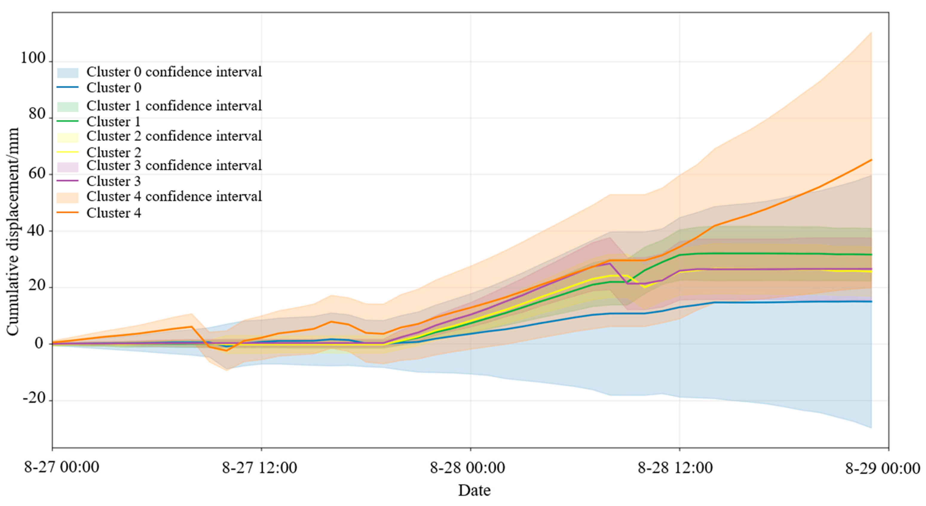
Figure 8 shows the clustering results of radar monitoring data from the slope. As seen in the figure, six clusters were identified from the Bayan Obo Mine southern slope radar monitoring point cloud, with Cluster −1 being classified as noise. Except for Clusters 0 and 4, the remaining clusters have relatively small surface areas and limited impact on overall slope stability.
By observing the clustering cloud map, it can be seen that there are clusters with a larger number of points and greater cumulative displacement between the 1650 m and 1570 m platforms. Among them, Cluster 4 is located between 1570 m and 1626 m. The displacement time series curve of this cluster is shown in Figure 9.
It is relatively clear from the above figure that the southern slope experienced a slow–rapid–accelerated deformation phase between 27 August and 29 August. All six clusters showed relatively small cumulative displacements in the early stage. Around 18:00 on 27 August, the displacement change of Cluster 0 began to lag behind the other five clusters. From 12:00 on 28 August onward, the cumulative displacement of Cluster 4 began to increase significantly, reaching over 60 mm on 29 August—the maximum displacement before the landslide occurred. According to the resistivity profile and geological cross-section along the survey line, the area where Cluster 4 is located contains a fault fracture zone and an adverse-dip structural plane, with a high degree of weathering. Under the combined influence of these factors, the slope in this area became unstable, which explains why Cluster 4 exhibited the greatest displacement.
These results indicate that the proposed method leverages the spatiotemporal continuity of radar remote sensing data from the slope surface, effectively avoiding false alarms caused by monitoring data from small areas or isolated points. It also allows for more accurate monitoring and early warning of landslide scale and deformation stages.
As shown in the figure, Cluster 4 exhibits the largest mean cumulative displacement, and its displacement curve shows non-stationary characteristics. In the subsequent analysis, VMD will be applied to decompose the displacement curve of Cluster 4. The low- and mid-frequency components after decomposition will be predicted using the GRU and LSTM neural networks in order to reveal the characteristics of their displacement evolution.

3.2. Slope Displacement Decomposition Results

The parameters for VMD decomposition were optimized using PSO. The specific parameter settings are shown in Table 3, and the PSO optimization results are presented in Table 4.
Using the optimized parameters, the total displacement was decomposed into trend component displacement (reflecting long-term trends influenced by geological conditions like lithology and structure) and periodic component displacement (driven by external factors such as rainfall).
The decomposition effect of trend component displacement is shown in Figure 10. As seen in the figure, the trend component displacement curve is smoother than the original displacement curve, with high-frequency components removed. The original displacement curve exhibits several minor declines, while the trend component does not follow these declines, indicating that VMD successfully filtered out short-term disturbances and focused on long-term trends. The close alignment between the trend component and the original curve demonstrates a clear and rapidly increasing trend during this stage.
The decomposition effects of periodic component displacement and rainfall data are shown in Figure 11. The periodic component displacement curve exhibits intense fluctuations with multiple peaks, representing high-frequency disturbance components. The current rainfall period shows multiple significant surges in rainfall, which align with the abrupt fluctuations in the displacement curve. The proximity of peaks between the two curves indicates that the current rainfall has a notable triggering effect, rapidly increasing the surface moisture content and pore water pressure, thereby inducing displacement disturbances. Rainfall fluctuations from the previous two days exhibit similarities to the displacement curve two days later, reflecting the lagged effect of rainfall.
The southern slope of the Bayan Obo Iron Mine features well-developed joint fractures and fault structures, along with water-sensitive minerals such as mica and montmorillonite. These minerals undergo disintegration and volume expansion upon water contact, confirming the significant impact of rainfall on landslide displacement. To visually quantify the correlation between rainfall and periodic component displacement, Grey Relational Degree analysis was employed. The specific workflow included using periodic component displacement, current rainfall, and prior two-day rainfall as input data; normalizing the data; calculating difference sequences and extremum values; and using these results to compute relational coefficients and GRD. A resolution coefficient ρ=0.5 was introduced to balance sensitivity and stability. The relationship between current rainfall, prior two-day rainfall, and periodic component displacement is illustrated in the figure, with GRD results listed in Table 5. The GRD values for current rainfall and prior two-day rainfall relative to periodic component displacement are 0.7008 and 0.5770, respectively, both exceeding 0.5, indicating strong correlations.

3.3. Trend Component Displacement Prediction

The training progress is shown in Figure 12, where RMSE and loss decrease and stabilize with increasing iterations. Figure 13 displays the prediction results, with the evaluation metrics shown in 
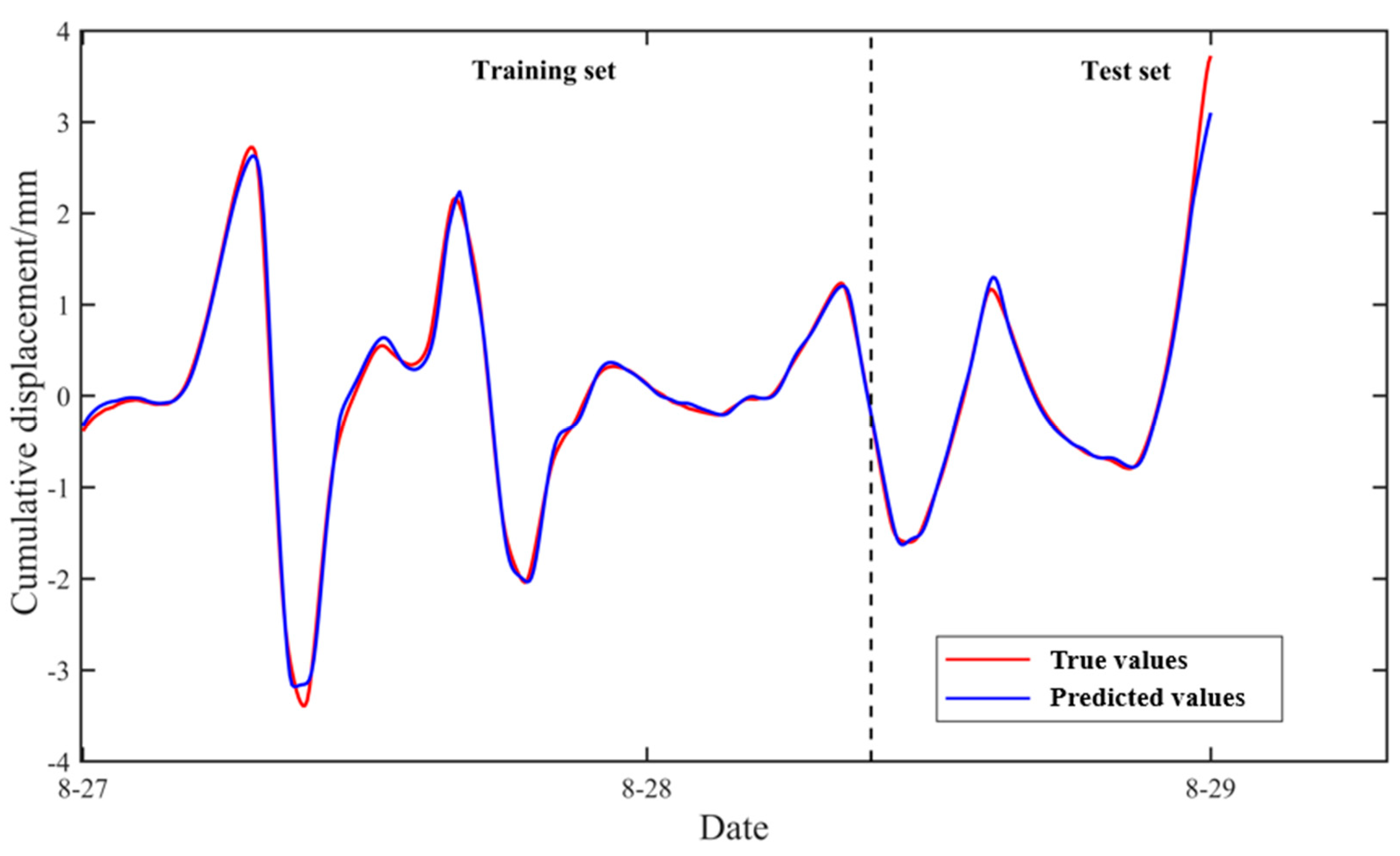
Table 6. RMSE = 0.94794, MAE = 0.46536, and R2 = 0.99755 validate the effectiveness of the GRU network in trend component prediction. During the training phase, the predicted and true values align closely, with nearly overlapping curves, indicating strong fitting capability on existing data. In the testing phase, despite using unseen data, the prediction curves closely match the true values with accurate overall trends, demonstrating robust generalization. Even in phases with rapid changes, GRU maintains stable trend tracking with minimal errors.
To further validate the GRU model’s performance, comparisons were made with the ARIMA, LSTM, and TCN models under the same dataset, as shown in Figure 14. GRU consistently adheres to the true value curve throughout the prediction period, particularly excelling in rapid growth phases with superior trend capture capability. Quantitative metrics (Table 7) show that GRU’s RMSE (0.94794) is significantly lower than the RMSE values of the other models, indicating minimal prediction error. Its R2 (0.99755) reflects near-perfect data variation explanation, while its MAE (0.46536) confirms the smallest average deviation from observed values. All models perform similarly in the early stages, but during rapid late-stage growth, ARIMA exhibits clear underfitting due to limited linear modeling for complex nonlinear sequences. The LSTM predictions are systematically low with delayed responses at trend inflection points, suggesting potential overfitting or insufficient learning. TCN fails to capture rapid displacement increases, revealing inadequate mid-to-long-term trend modeling.

3.4. Periodic Component Displacement Prediction

Since the data were normalized before training, the prediction results needed to be rescaled back to their original scale for comparison with the true values. Figure 15 and Figure 16 display the predicted results, and the corresponding evaluation metrics—RMSE, R2, and MAE—are presented in Table 8. For the LSTM model, the RMSE and MAE on the training set are 0.0816 and 0.0585, respectively, with an R2 value of 0.9948, indicating an excellent fit to the training data and demonstrating the model’s strong ability to capture temporal patterns.
On the test set, while the RMSE and MAE increase slightly to 0.1278 and 0.0635, and R2 drops to 0.9873, the performance remains at a high level, showing that the model maintains strong generalization and prediction capability when dealing with unseen data. For the entire dataset, the overall RMSE and MAE are 0.0978 and 0.0600, respectively, and R2 reaches as high as 0.9925, further validating the effectiveness of the LSTM network in periodic component prediction.
To intuitively evaluate the prediction performance of LSTM, three other models were used for comparison: RNN, GRU, and CNN. The prediction results are shown in Figure 17, and their evaluation metrics are listed in Table 9.
From both the figure and the table, it is clear that LSTM achieves the best prediction performance. Its predicted values are the closest to the actual observations, indicating that LSTM’s gating mechanism (forget gate, input gate, output gate) is highly effective in capturing long-term periodic patterns and mitigating gradient vanishing problems. LSTM has the lowest RMSE and highest R2, suggesting that it nearly perfectly fits the data.
GRU, with its simplified gating structure (update and reset gates), performs well on periodic sequences but is slightly less capable than LSTM when modeling complex periodic dynamics. Compared to RNN and CNN, GRU achieves a lower RMSE and MAE, supporting the effectiveness of gating mechanisms.
The standard RNN model struggles with long-term dependencies due to the gradient vanishing issue, leading to significantly higher errors than LSTM and GRU. Meanwhile, CNN, being more suited for spatial data, is not ideal for purely temporal periodic sequences. Its reliance on local convolution kernels limits its ability to directly capture global periodic patterns.

3.5. Total Displacement Prediction

After separately predicting the trend and periodic components of the displacement, the final landslide displacement prediction for Cluster 4 was obtained by reconstructing and superimposing the results. The total displacement prediction is illustrated in Figure 18. Quantitative evaluation using RMSE, MAE, and R2 yields RMSE = 0.9948 mm, MAE = 0.4960 mm, and R2 = 0.9973, indicating a high level of overall prediction accuracy.

4. Discussion

In multi-scale landslide displacement modeling, the quality of signal decomposition directly influences the stability and interpretability of prediction results. Compared to traditional methods, such as EMD, EEMD, and wavelet analysis [14,15,16,17,18,19,20,21,22], the VMD approach adopted in this study demonstrates significant advantages. It distinctly separates displacement sequences into a long-term trend component controlled by geological structures and a high-frequency periodic component influenced by rainfall disturbances, thereby providing physically meaningful intrinsic modes for subsequent modeling. Unlike EEMD, VMD eliminates the need for multi-round perturbation superposition and reconstruction during decomposition, resulting in higher computational efficiency. This makes it more suitable for rapid early warning modeling in practical engineering scenarios. Furthermore, the framework’s robust predictive performance confirms the superiority of VMD, demonstrating reliable capabilities in real-world slope monitoring applications.
For predictive modeling, this study employs a hybrid “trend component-GRU, periodic component-LSTM” strategy, which shows notable advantages over existing approaches that uniformly apply a single network model to all components. For instance, Xie et al. [30], Xing et al. [31], and Yang et al. [32] utilized LSTM models for full displacement sequence modeling, while Zhang et al. [33,34] applied GRU models to holistically predict landslide displacement. While these methods exhibit certain predictive capabilities in handling complex temporal data, they fail to distinguish the dynamic differences between trend and periodic components, often leading to feature ambiguity or structural underfitting during modeling. Through our component-specific matching strategy, the GRU model achieves an R2 value of 0.99755 in trend component prediction, significantly outperforming comparative models including ARIMA, TCN, and even LSTM (Table 7). This highlights GRU’s advantages in capturing slow-varying trends with fewer parameters and faster convergence. Simultaneously, the LSTM model attains the lowest RMSE (0.0978 mm) in periodic component prediction, surpassing the traditional RNN, CNN, and GRU models (Table 9), demonstrating its strength in modeling complex periodic disturbances and high-frequency responses. The final PSO-VMD-GRU/LSTM framework achieves an overall displacement prediction R2 of 0.9973, further validating the effectiveness of component-specific modeling in enhancing prediction accuracy and model generalization capabilities.
Although the proposed framework is constructed based on data from the Bayan Obo open-pit iron mine, its core methodology exhibits strong transferability. Notably, the DBSCAN algorithm identifies early warning units through spatiotemporal density distributions of monitoring points, independent of specific geological types. This makes the method applicable to other open-pit mine slopes with dense displacement monitoring data. However, broader implementation requires careful consideration of the following prerequisites: First, the method depends on high-temporal-resolution monitoring data as foundational support. This study utilizes hourly interval, ground-based radar data comprising 114,283 monitoring points, each containing 48 h of continuous displacement records, which provide the necessary data integrity for VMD decomposition and periodic feature extraction. It should be noted that the decomposition results and subsequent prediction model performance would be significantly degraded under conditions of sparse sampling intervals, data discontinuity, or abnormal missing values. Second, the prediction of periodic components is highly dependent on rainfall as an external driver. However, the rainfall–displacement coupling relationship is not universally applicable. In regions with minimal rainfall fluctuations, arid climates, or complex hydrogeological conditions, this coupling may exhibit weak correlations or significant time lags, necessitating the introduction of alternative drivers, such as groundwater levels or hydraulic pressures, or structural model adaptations to accommodate regional characteristics. Third, lithological characteristics fundamentally govern slope response mechanisms to external disturbances. The rock mass in the Bayan Obo mining area primarily contains water-sensitive minerals (e.g., mica, montmorillonite) with developed joint fractures. In contrast, regions with homogeneous lithology, compact structures, or dry stable conditions often show atypical rainfall-induced displacement responses, leading to difficulties in periodic component extraction and reduced prediction model stability. Finally, the framework exhibits sensitivity to multiple critical parameters: DBSCAN’s ε and MinPts settings, VMD’s mode number selection, and hyperparameter configurations in LSTM/GRU networks. Optimal parameter combinations may vary substantially across regions. Therefore, during implementation, cross-validation or sensitivity analysis should be conducted based on regional geological and climatic features.
To assess the computational feasibility of the proposed method for near-real-time warning systems, this study evaluates the computational demands of the PSO-VMD algorithm and the training efficiency of deep neural networks. On a standard computer equipped with an Intel Core i5-13400F CPU and 16GB RAM, the PSO-VMD algorithm completes one parameter optimization cycle (with particle swarm size set to 10 and maximum iterations to 100) in approximately 30 s on average, demonstrating low resource consumption without reliance on GPUs or high-performance servers. Under identical hardware conditions, the training processes of both LSTM and GRU models are completed within 1 min. Comprehensive tests confirm that the method achieves high prediction accuracy with low computational demands and rapid response times, meeting the essential computational performance criteria of near-real-time landslide early warning systems.

5. Conclusions

This study addressed the limitations of traditional landslide early warning methods in open-pit mines, specifically their insufficient consideration of spatiotemporal correlation and the challenges in modeling displacement sequences with multi-scale coupling. To tackle these issues, a novel landslide prediction framework was proposed, integrating DBSCAN clustering with PSO-VMD for multi-scale decomposition.
Using the southern slope of the Bayan Obo main open-pit mine as the research area, and leveraging the spatiotemporal continuity of radar monitoring data, high-risk deformation regions were identified through DBSCAN clustering. Combined with PSO-VMD decomposition and hybrid prediction models, the framework successfully revealed the multi-scale dynamic mechanisms underlying slope displacement evolution. The main conclusions are as follows:
1. By applying a parameter-optimized DBSCAN algorithm to radar point cloud data, Cluster 4—characterized by high average cumulative displacement and wide spatial distribution (located in the 1598–1626 m platform zone)—was successfully identified. This method effectively suppressed outlier interference, and the resulting early warning outputs closely matched the actual spatial–temporal patterns of the landslide.
2. The displacement of Cluster 4 was decomposed into trend and periodic components using VMD optimized by PSO. The trend component captured long-term displacement evolution, with the GRU model achieving a high prediction accuracy (R2 = 0.99755). The periodic component reflected the nonlinear response to hydrological disturbances, and the LSTM model achieved a superior performance with RMSE = 0.0978 mm, significantly outperforming the RNN, GRU, and CNN models. The reconstructed total displacement prediction reached an R2 of 0.9973, further confirming the effectiveness of the multi-scale decomposition framework.
Despite the above results, several limitations remain in the present study. While the Discussion Section highlighted potential challenges in applying the proposed framework to different geological contexts, the current stage of this research still presents certain limitations—particularly in terms of model validation. The proposed framework currently relies on radar displacement curves as the primary validation source. Although manual field inspections prior to the landslide revealed surface cracking and ground bulging in the predicted high-risk area (Cluster 4), no quantitative ground-based monitoring data were available for independent verification. In future work, we plan to incorporate GNSS-based displacement measurements, geological mapping, groundwater sensors, and crack meters to further enhance the model’s stability and generalizability under complex geological and hydrological conditions. Moreover, future developments may explore embedding the framework into real-time monitoring systems to support timely decision-making in mine slope management.
The proposed “Spatiotemporal Clustering–Multi-Scale Decomposition–Hybrid Prediction” framework enables the identification of landslide-prone regions on larger spatial scales and enhances both the accuracy and robustness of displacement prediction. This method offers a promising new technical solution for improving precursor identification of slope instability and ensuring the safety of slope monitoring in open-pit mining operations.

Author Contributions

Methodology, P.Z., Y.L. and H.L.; software, P.Z., Y.L. and X.D.; validation, P.Z. and Y.L.; formal analysis, P.Z., Y.L. and X.D.; investigation, P.Z., Y.L. and T.Y.; resources, Y.L., T.Y. and H.L.; data curation, Y.L., X.D. and H.L.; writing—original draft, Y.L.; writing—review and editing, P.Z. and T.Y.; supervision, P.Z. and X.D. All authors have read and agreed to the published version of the manuscript.

Funding

The work presented in this paper was financially supported by the National Key R&D Program of China (Grant No. 2022YFC2903903) and the National Natural Science Foundation of China (Grant No. 52174070).

Institutional Review Board Statement

Not applicable.

Informed Consent Statement

Not applicable.

Data Availability Statement

The raw data supporting the conclusions of this article will be made available by the authors on request.

Conflicts of Interest

The funders had no role in the design of this study; in the collection, analyses, or interpretation of data; in the writing of this manuscript; or in the decision to publish the results.

Appendix A

GRU contains two key gating structures:
Update Gate: The update gate determines how much of the previous hidden state is retained and how much new information is introduced, as shown in Equation (A1).
z t = σ W z · h t 1 , x t + b z
where x t is the current input, h t 1 is the previous hidden state, W z and b z are the weight matrix and bias term of the update gate, and σ is the Sigmoid activation function with outputs in [0, 1].
Reset Gate: The reset gate determines how much of the previous hidden state is “forgotten” to generate the candidate hidden state, as shown in Equation (A2).
r t = σ W r · h t 1 , x t + b r
where x t is the current input, h t 1 is the previous hidden state, W r and b r are the weight matrix and bias term of the reset gate, and σ is the Sigmoid activation function.
The core of GRU lies in the collaboration between the update gate and reset gate, as well as the progressive update of the hidden state. The candidate hidden state integrates information from the reset gate to generate a temporary hidden state at the current time step, as shown in Equation (A3).
h t ~ = t a n h W h · r t h t 1 , x t + b h
where denotes element-wise multiplication (Hadamard product) and W h and b h are the weight matrix and bias term.
The final hidden state combines the output of the update gate, fusing previous information with the current candidate state, as shown in Equation (A4).
h t = ( 1 z t ) h t 1 + z t h t ~
where z t controls the weights of old and new information. If z t approaches 0, more historical information is retained.
As shown in Figure A1, GRU first combines the current input x t and the previous hidden state h t 1 to generate two gating signals. Specifically, the update gate z t and reset gate r t output values between 0 and 1 via the Sigmoid function, corresponding to “the degree of retaining old states” and “the degree of forgetting historical information,” respectively.
Figure A1. Structure diagram of GRU.
Applsci 15 06068 g0a1
Next, the reset gate value r t acts on the previous hidden state h t 1 through element-wise multiplication ( r t h t 1 ), selectively filtering out irrelevant historical information. This operation resembles “resetting” certain long-term memories while retaining content useful for the current time step. Subsequently, the filtered historical state and current input x t are combined to generate a candidate hidden state h t ~ , which uses the tanh activation function to capture potential new information at the current time step, achieving preliminary fusion of current input and historical information.
Finally, the update gate z t performs a weighted average of the old state h t 1 and candidate state h t ~ . If the value of the update gate is close to 1, the candidate state dominates the current output, that is, it tends to learn new information. If it is close to 0, more historical states will be retained, that is, long-term dependence will be maintained.

Appendix B

LSTM introduces memory cells and gating mechanisms to control information storage/forgetting, overcoming traditional RNN limitations. LSTM primarily includes three gating structures:
Forget Gate: The forget gate determines the retention or discard of historical information, as shown in Equation (A5).
f t = σ W f · h t 1 , x t + b f
where x t is the current input, h t 1 is the previous hidden state, W f and b f are the weight matrix and bias term, and σ is the Sigmoid activation function with outputs in [0, 1].
Input Gate: The input gate controls whether the current input information is added to the memory cell, as shown in Equations (A6) and (A7).
i t ˙ = σ W i · h t 1 , x t + b i
C t ~ = tanh W C · h t 1 , x t + b C
where i t ˙ is the input gate activation value and C t ~ is the candidate cell state using tanh activation for information smoothness.
The memory cell state update is shown in Equation (A8).
C t = f t C t 1 + i t C t ~
where denotes element-wise multiplication (Hadamard product) and C t is the updated memory cell state.
Output Gate: The output gate determines current output by controlling information passed to the next hidden state h t , normalized via tanh, as shown in Equations (A9) and (A10).
o t = σ W o · h t 1 , x t + b o
h t = o t tanh C t
where o t is the output gate activation value and h t is the hidden state at current time step.
As shown in Figure A2, each line connecting one node’s output to another node’s input represents a complete vector. The circles denote pointwise operations, such as vector addition, while the boxes indicate the neural network layers that are learned during training.
Figure A2. Structure diagram of LSTM.
Applsci 15 06068 g0a2
The core of LSTM is the cell state, represented by the horizontal line running across the top of the diagram. The cell state functions somewhat like a conveyor belt. It flows through the entire chain with only minor linear interactions, making it easy for information to pass unchanged along it. LSTM has the ability to add or remove information from the cell state, carefully regulated by structures called gates.
The gates are mechanisms that selectively allow information to pass through. Each gate consists of a sigmoid neural network layer and a pointwise multiplication operation. The sigmoid layer outputs values between 0 and 1, indicating the proportion of each component that should be allowed through. A value of 0 means “block everything”, while 1 means “let everything through”. LSTM contains three such gates to protect and control the cell state.
The first step in an LSTM analysis is to decide what information to forget from the cell state. This decision is made by the forget gate layer, a sigmoid layer that takes h t 1 and x t as inputs and outputs values between 0 and 1 for each component of the cell state. The next step is to decide what new information to store in the cell state. First, the input gate layer, another sigmoid network, determines which values will be updated. Then, a tanh layer generates a vector of candidate values, C t ~ , that could be added to the state. In the following step, these two components are combined to update the state. This update is governed by the cell state update equation (Equation (A8)), where the old state is partially forgotten and the new candidate values are added, each scaled by how much we decided to update that state component.
Finally, the information is output. This output will be based on the cell state. First, a Sigmoid layer is run to determine which parts of the cell state we want to output. Then, the cell state is converted to a value between −1 and 1 through tanh and multiplied by the output of the Sigmoid gate. In this way, the parts we decide to output can be output.

References

  1. Yang, T.-H.; Zhang, F.-C.; Yu, Q.-L.; Cai, M.-F.; Li, H.-Z. Current research status and development trends of high and steep slope stability in open-pit mines. Rock Soil Mech. 2011, 32, 1437–1451, 1472. [Google Scholar]
  2. Hu, S.-S.; Xiao, Y.-H.; Wen, T.; Wei, H.-N.; Li, W. Application of GNSS technology in monitoring bedding slopes of open-pit mines. Min. Technol. 2023, 23, 122–126. [Google Scholar]
  3. Zhang, H.-H. Study on Multi-Source Collaborative Monitoring Method for Large Deformation Landslides in the Xilu Open-Pit Mine of Fushun. Ph.D. Thesis, Northeastern University, Shenyang, China, 2019. [Google Scholar]
  4. Liu, X.-S.; Zhang, X.-Z.; Wang, A.-G. Automatic monitoring system for slope stability. J. China Coal Soc. 2007, 32, 473–476. [Google Scholar]
  5. Cui, X.; Yang, S.-L. Surface rock movement evolution and stability analysis induced by underground mining. Min. Res. Dev. 2023, 43, 78–83. [Google Scholar]
  6. Qin, X.-S.; Zhang, D.; Cao, H. Current research status and development trends of monitoring technology for high and steep slopes in open-pit mines. China Min. Mag. 2017, 26, 107–111. [Google Scholar]
  7. Li, Y.-Z.; Shen, J.-H.; Zhang, W.-X.; Zhang, K.-Q.; Peng, Z.-H.; Huang, M. Slope deformation partitioning and monitoring points optimization based on cluster analysis. J. Mt. Sci. 2023, 20, 2405–2421. [Google Scholar] [CrossRef]
  8. Cai, W.-Z.; Li, C.; Zhang, R.-T.; Wu, L.-L.; Zhang, X.-Z.; Cheng, F.; Li, S.-J.; Xiao, Z.-Y. Study on probabilistic early warning model for slope monitoring based on catastrophe theory. Sci. Technol. Eng. 2023, 23, 10229–10235. [Google Scholar]
  9. Zhou, Y.; Wang, X.-R.; Zhu, Y.-P.; Li, J.-B.; Jiang, X.-K. Monitoring and numerical simulation of high slopes with strongly weathered interbedded soft and hard rock. Rock Soil Mech. 2018, 39, 2249–2258. [Google Scholar]
  10. Wang, J.; Chen, K.; Li, T.; Li, M.; Jiang, R.; Zhang, H.; Song, T. A new method of monitoring slope displacement using millimeter wave radar. Landslides 2025, 22, 1693–1706. [Google Scholar] [CrossRef]
  11. Zhan, J.; Yang, K.; Dong, X.; Wang, Z.; Zhu, H.; Duan, C. New modeling method of millimeter-wave radar considering target radar echo intensity. Proc. Inst. Mech. Eng. 2021, 235, 2857–2870. [Google Scholar]
  12. Manconi, A.; Jones, N.; Loew, S.; Strozzi, T.; Caduff, R.; Wegmueller, U. Monitoring surface deformation with spaceborne radar interferometry in landslide complexes: Insights from the Brienz/Brinzauls slope instability, Swiss Alps. Landslides 2024, 21, 2519–2533. [Google Scholar] [CrossRef]
  13. Tan, W.-X.; Wang, Y.-D.; Huang, P.-P.; Qi, Y.-L.; Xu, W.; Li, C.-M.; Chen, Y.-J. A method for predicting landslides based on micro-deformation monitoring radar data. Remote Sens. 2023, 15, 826. [Google Scholar] [CrossRef]
  14. Li, J.; Tan, Z.; Zeng, N.; Xu, L.; Yang, Y.; Siddique, A.; Dang, J.; Zhang, J.; Wang, X. Wavelet-based analysis of subsidence patterns and high-risk zone delineation in underground metal mining areas using SBAS-InSAR. Land 2025, 14, 992. [Google Scholar] [CrossRef]
  15. Zhou, C.; Yin, K.-L.; Huang, F.-M. Application of Chaos-Based WA-ELM Coupled Model in Landslide Displacement Prediction. Rock Soil Mech. 2015, 36, 2674–2680. [Google Scholar]
  16. Huang, F.-M.; Yin, K.-L.; Zhang, G.-R.; Gui, L.; Yang, B.-B.; Liu, L. Landslide Displacement Prediction Using Discrete Wavelet Transform and Extreme Learning Machine Based on Chaos Theory. Environ. Earth Sci. 2016, 75, 1376. [Google Scholar] [CrossRef]
  17. Xu, S.-L.; Niu, R.-Q. Displacement Prediction of Baijiabao Landslide Based on Empirical Mode Decomposition and Long Short-Term Memory Neural Network in Three Gorges Area, China. Comput. Geosci. 2018, 111, 87–96. [Google Scholar] [CrossRef]
  18. Zhang, K.; Zhang, K.; Bao, R.; Liu, X.-H.; Qi, F.-F. Intelligent Landslide Displacement Prediction Based on Optimized Empirical Mode Decomposition and Cluster Analysis. Rock Soil Mech. 2021, 42, 211–223. [Google Scholar]
  19. Yuan, W.; Sun, R.-F.; Zhong, H.-Y.; Jiao, H.-M.; Hu, H.-H.; Lin, H. Study on Comprehensive Deformation Prediction and Monitoring–Early Warning Method for Step-like Landslides. J. Hydraul. Eng. 2023, 54, 461–473. [Google Scholar]
  20. Liu, H.-Y.; Chen, W.-T.; Li, Y.-Y.; Xu, Z.-Y.; Li, X.-J. Application of a Novel EEMD-CNN-LSTM Integrated Model in Landslide Displacement Prediction. J. Geomech. 2024, 30, 633–646. [Google Scholar]
  21. Kang, E.-S.; Zhao, Z.-X.; Meng, H.-D. Landslide Displacement Prediction of Dump Slope Based on EEMD-HW-PSO-ELM Coupled Model. Gold Sci. Technol. 2022, 30, 594–602. [Google Scholar]
  22. Deng, D.-M.; Liang, Y.; Wang, L.-Q.; Wang, C.-S.; Sun, Z.-H.; Wang, C.; Dong, M.-M. Displacement Prediction Method Based on Ensemble Empirical Mode Decomposition and Support Vector Regression: A Case Study of a Landslide in the Three Gorges Reservoir Area. Rock Soil Mech. 2017, 38, 3660–3669. [Google Scholar]
  23. Dragomiretskiy, K.; Zosso, D. Variational Mode Decomposition. IEEE Trans. Signal Process. 2014, 62, 531–544. [Google Scholar] [CrossRef]
  24. Huang, F.-M.; Yin, K.-L.; Yang, B.-B.; Li, X.; Liu, L.; Fu, X.-L.; Liu, X.-W. Step-Like Landslide Displacement Prediction Based on Time Series Decomposition and Multivariable Chaos Model. Earth Sci. 2018, 43, 887–898. [Google Scholar]
  25. Li, L.-W.; Wu, Y.-P.; Miao, F.-S.; Xue, Y.; Huang, Y.-P. Interval Prediction Method for Step-like Landslide Displacement Considering Dynamic Switching of Deformation States. Chin. J. Rock Mech. Eng. 2019, 38, 2272–2287. [Google Scholar]
  26. Senanayake, I.P.; Hartmann, P.; Giacomini, A.; Huang, J.; Thoeni, K. Prediction of Rockfall Hazard in Open Pit Mines Using a Regression-Based Machine Learning Model. Int. J. Rock Mech. Min. Sci. 2024, 177, 105727. [Google Scholar] [CrossRef]
  27. Zhang, W.-G.; Li, H.-R.; Han, L.; Chen, L.-L.; Wang, L. Slope Stability Prediction Using Ensemble Learning Techniques: A Case Study in Yunyang County, Chongqing, China. J. Rock Mech. Geotech. Eng. 2022, 14, 1089–1099. [Google Scholar] [CrossRef]
  28. Kardani, N.; Zhou, A.; Nazem, M.; Shen, S.-L. Improved Prediction of Slope Stability Using a Hybrid Stacking Ensemble Method Based on Finite Element Analysis and Field Data. J. Rock Mech. Geotech. Eng. 2021, 13, 188–201. [Google Scholar] [CrossRef]
  29. Baghbani, A.; Choudhury, T.; Costa, S.; Reiner, J. Application of Artificial Intelligence in Geotechnical Engineering: A State-of-the-Art Review. Earth-Sci. Rev. 2022, 228, 103991. [Google Scholar] [CrossRef]
  30. Xie, P.-H.; Zhou, A.-G.; Chai, B. The Application of Long Short-Term Memory (LSTM) Method on Displacement Prediction of Multifactor-Induced Landslides. IEEE Access 2019, 7, 54305–54311. [Google Scholar] [CrossRef]
  31. Xing, Y.; Yue, J.; Chen, C. Interval Estimation of Landslide Displacement Prediction Based on Time Series Decomposition and Long Short-Term Memory Network. IEEE Access 2020, 8, 3187–3196. [Google Scholar] [CrossRef]
  32. Yang, B.-B.; Yin, K.-L.; Lacasse, S.; Liu, Z.-Q. Time Series Analysis and Long Short-Term Memory Neural Network to Predict Landslide Displacement. Landslides 2019, 16, 677–694. [Google Scholar] [CrossRef]
  33. Zhang, Y.-G.; Tang, J.; He, Z.-Y.; Tan, J.-K.; Li, C. A Novel Displacement Prediction Method Using Gated Recurrent Unit Model with Time Series Analysis in the Erdaohe Landslide. Nat. Hazards 2021, 105, 783–813. [Google Scholar] [CrossRef]
  34. Zhang, W.-G.; Li, H.-R.; Tang, L.-B.; Gu, X.; Wang, L.-Q.; Wang, L. Displacement Prediction of Jiuxianping Landslide Using Gated Recurrent Unit (GRU) Networks. Acta Geotech. 2022, 17, 1367–1382. [Google Scholar] [CrossRef]
  35. Li, J.-D.; Gao, Y.; Yang, T.-H.; Zhang, P.-H.; Zhao, Y.; Deng, W.-X.; Liu, H.-L.; Liu, F.-Y. Integrated Simulation and Monitoring to Analyze Failure Mechanism of the Anti-Dip Layered Slope with Soft and Hard Rock Interbedding. Int. J. Min. Sci. Technol. 2023, 33, 1147–1164. [Google Scholar] [CrossRef]
  36. Li, J.-D.; Yang, T.-H.; Deng, W.-X.; Du, S.-G.; Zhang, Z.-R.; Ma, H.-T.; Wang, H.; Guo, J.-T.; Liu, L.-J. Evaluating Failure Mechanisms of Excavation-Induced Large-Scale Landslides in Xinjing Open-Pit Coal Mine Through Integrated UAV Imagery and 3D Simulation. Landslides 2025, 22, 2021–2036. [Google Scholar] [CrossRef]
  37. Feng, Q.; Li, Q.; Quan, W.; Pei, X.-M. Review of Multi-Objective Particle Swarm Optimization Algorithm. J. Eng. Sci. 2021, 43, 745–753. [Google Scholar]
Figure 1. Cross-sectional view at the middle part of the landslide.
Applsci 15 06068 g001
Figure 2. Current status of the southern slope landslide.
Applsci 15 06068 g002
Figure 3. Radar cloud maps at different time periods.
Applsci 15 06068 g003
Figure 4. Cumulative variance explained rate curve.
Applsci 15 06068 g004
Figure 5. K-distance plot.
Applsci 15 06068 g005
Figure 6. Silhouette coefficient heatmap. The red star indicates the optimal parameter.
Applsci 15 06068 g006
Figure 7. Basic flowchart of PSO-VMD.
Applsci 15 06068 g007
Figure 8. Clustering effect diagram of slope radar monitoring data.
Applsci 15 06068 g008
Figure 9. Cumulative displacement curve.
Applsci 15 06068 g009
Figure 10. Trend component displacement.
Applsci 15 06068 g010
Figure 11. Relationship between periodic displacement and rainfall.
Applsci 15 06068 g011
Figure 12. Training progress diagram.
Applsci 15 06068 g012
Figure 13. Prediction results.
Applsci 15 06068 g013
Figure 14. Comparison of multi-model displacement predictions.
Applsci 15 06068 g014
Figure 15. Prediction results.
Applsci 15 06068 g015
Figure 16. Ratio of the predicted values to the true values. (a) The ratio of the predicted values to the true values in the training set; (b) the ratio of the predicted values to the true values in the test set.
Applsci 15 06068 g016
Figure 17. Comparison of multi-model predictions for the periodic component.
Applsci 15 06068 g017
Figure 18. Total displacement prediction results.
Applsci 15 06068 g018
Table 1. Parameter settings for the GRU model.
Optimization AlgorithmMaximum Number of EpochsInitial Learning RateLearning Rate Drop FactorLearning Rate Drop Period
Adam10005 × 10⁻30.1500
Table 2. Parameter settings for the LSTM model.
Optimization AlgorithmMaximum Number of EpochsInitial Learning RateLearning Rate Drop FactorLearning Rate Drop Period
Adam10005 × 10⁻30.1300
Table 3. Parameter settings for PSO.
Population SizeMaximum
Number of
Iterations
Learning
Factor
Learning
Factor
Inertia Weight
101001.51.50.8
Table 4. PSO optimization results.
Value of KAlphaBest Fitness Value
21500.014949
Table 5. GRD results.
RainfallGRD
Current Rainfall0.7008
Previous two-day rainfall0.5770
Table 6. Evaluation metrics of the GRU model.
DataRMSER2MAE
Training Set0.145440.999840.11474
Test Set2.09760.898381.8645
Overall Data0.947940.997550.46536
Table 7. Evaluation metrics of four models.
Predictive ModelRMSER2MAE
GRU0.947940.997550.46536
ARIMA4.3790.920982.9068
LSTM4.50710.944532.1568
TCN5.87630.905712.7592
Table 8. Evaluation metrics of the LSTM model.
DataRMSER2MAE
Training Set0.08160.99480.0585
Test Set0.12780.98730.0635
Overall Data0.09780.99250.0600
Table 9. Evaluation metrics of four models.
Predictive ModelRMSER2MAE
LSTM0.09780.99250.06000
RNN0.112650.99020.06494
GRU0.108290.990860.053993
CNN0.145890.983530.094195
Disclaimer/Publisher’s Note: The statements, opinions and data contained in all publications are solely those of the individual author(s) and contributor(s) and not of MDPI and/or the editor(s). MDPI and/or the editor(s) disclaim responsibility for any injury to people or property resulting from any ideas, methods, instructions or products referred to in the content.

