
Intelligent Dimension Annotation in Engineering Drawings: A Case-Based Reasoning and MKD-ICP Algorithm Approach


Abstract
1. Introduction
- We propose an innovative intelligent method for engineering drawing dimensioning, based on Case-Based Reasoning (CBR), K-Dimensional Tree (KD-Tree), and the improved Iterative Closest Point (ICP) algorithm.
- We propose a new method, the MKD-ICP algorithm, by combining the spatial search capability of KD-Tree with the point cloud matching technology of ICP, enabling the mapping and alignment of dimension information.
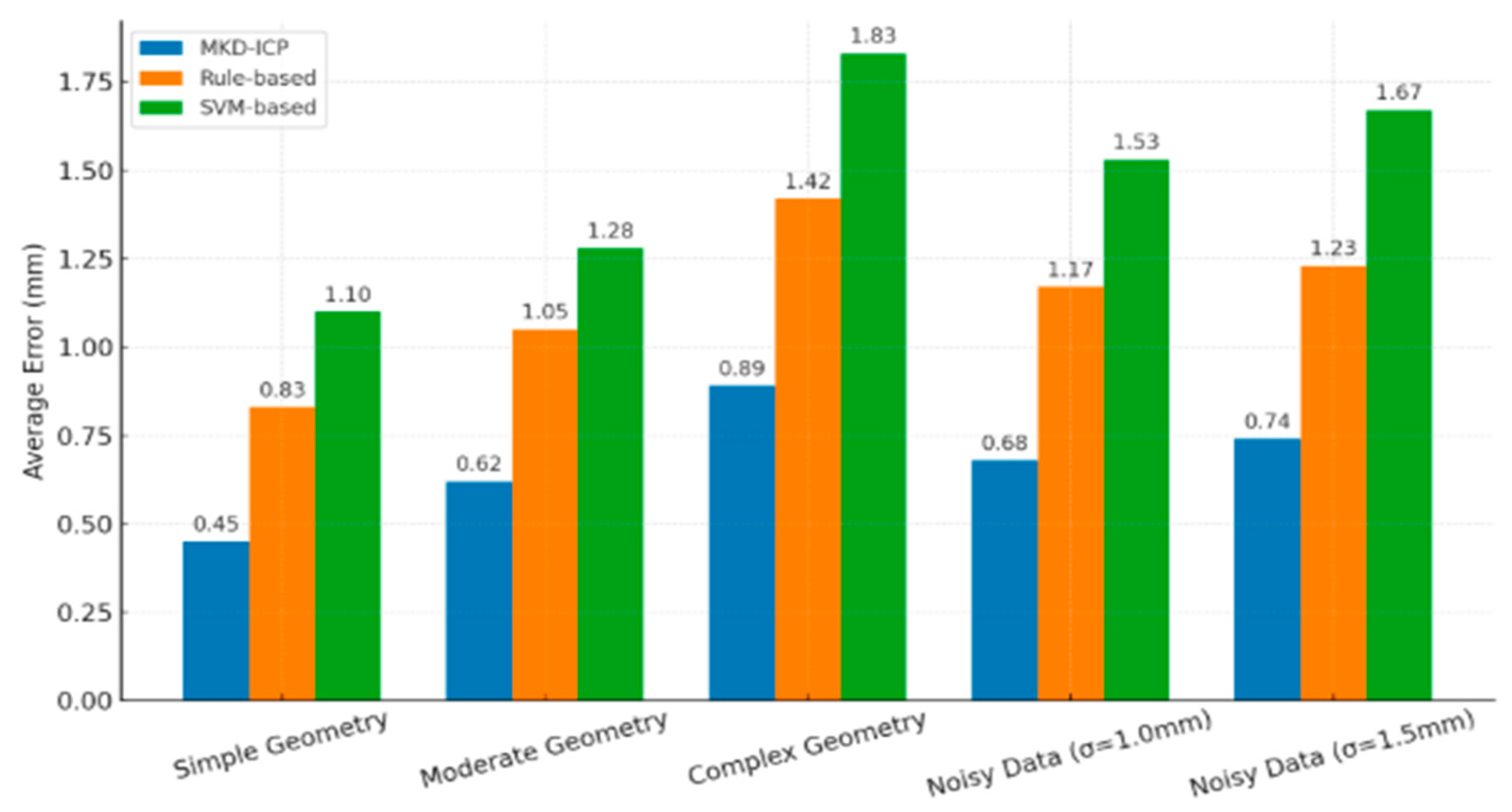
- We conducted an empirical study using a refrigerated van as a case, and the experimental results show that the proposed method significantly reduces human intervention and errors, accurately achieving automatic dimensioning of engineering drawings.
2. Related Works
2.1. Automatic Dimensioning of Engineering Drawings
2.2. Layout of Dimensions in Engineering Drawings
2.3. Dimension Completeness and Redundancy Checks
3. Methods
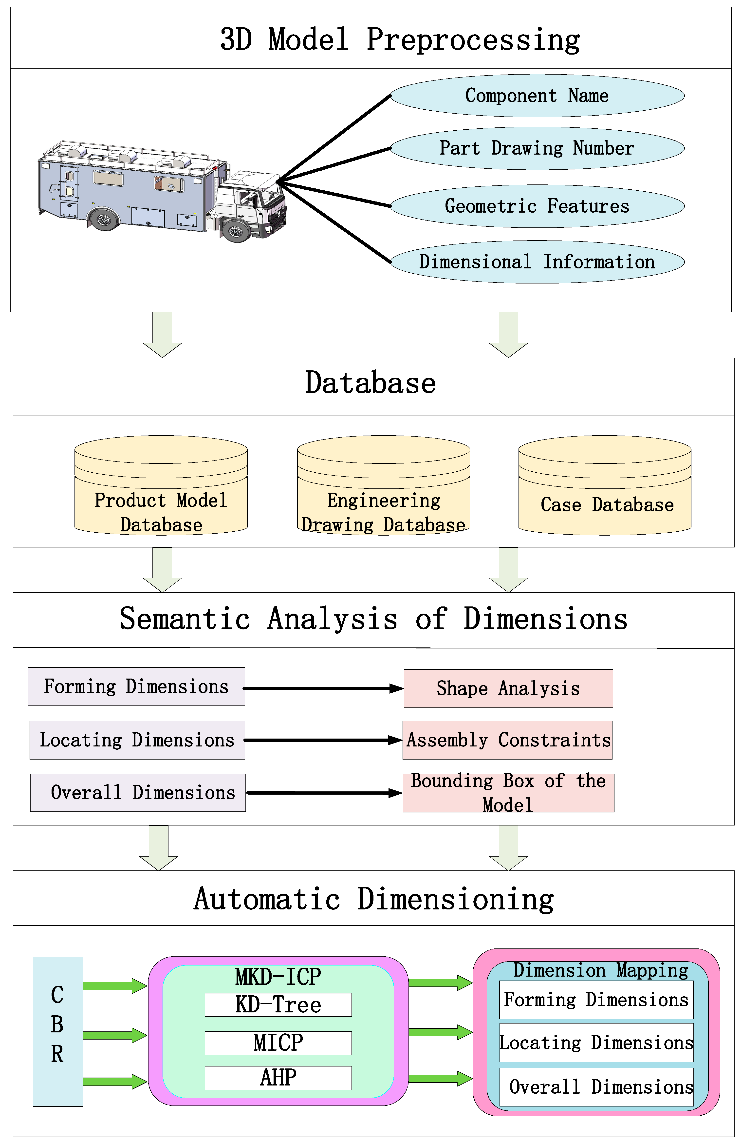
3.1. The Proposed Method
3.2. Dimensional Functional Semantic Analysis
- (1)
- Forming Dimensions: These describe the geometric features of an object, determining its fundamental shape and ensuring that the overall appearance of the product meets design requirements.
- (2)
- Locating Dimensions: These specify the relative positional features of an object, typically in reference to other features or reference points. They determine the relative positions of basic entities, ensuring the precision of component assembly.
- (3)
- Overall Dimensions: These describe the overall shape and size of the object, representing the total dimensions of all parts combined. They define the external size boundaries of the object, ensuring that the part fits the spatial requirements of the design environment.
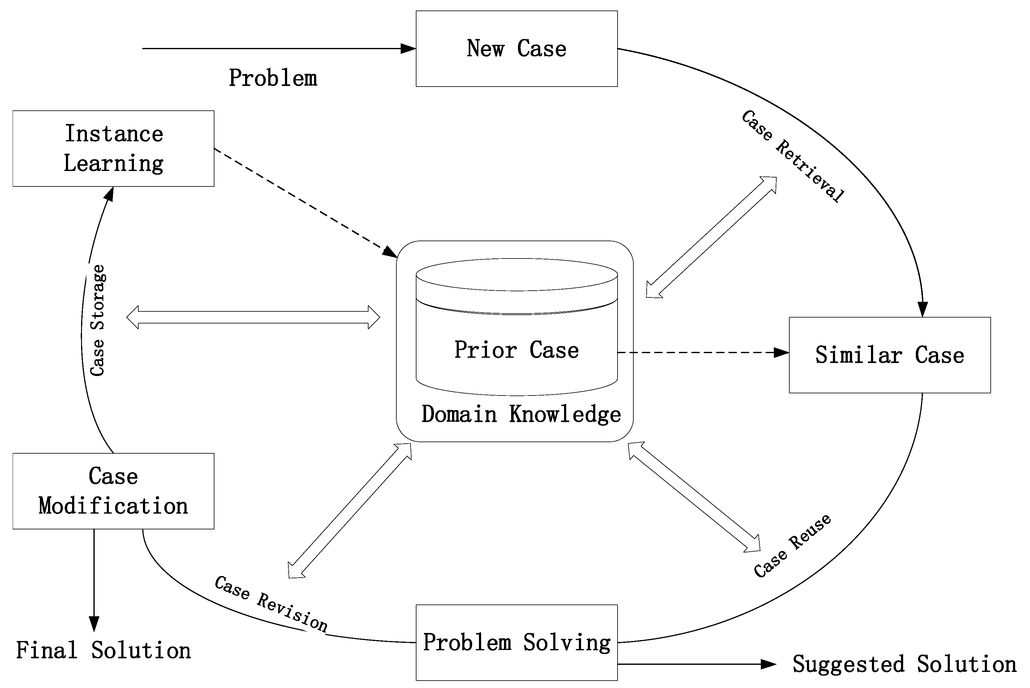
3.3. Case-Based Reasoning Technology
3.4. The Proposed Algorithm
3.5. Engineering Drawing Dimension Mapping
4. Results
5. Conclusions and Future Work
Author Contributions
Funding
Institutional Review Board Statement
Informed Consent Statement
Data Availability Statement
Conflicts of Interest
References
- Wang, Y.; Zhang, C.; Li, K.; Zhang, S. Research on Dimension Redundancy Checking Technology of Engineering Drawings Based on SolidWorks Secondary Development. Manuf. Technol. Mach. Tool 2023, 04, 72–77. [Google Scholar]
- Wu, S.; Yang, K. Research on Secondary Development of Parametric Assembly Design Based on Solid Edge. Boil. Technol. 2023, 54, 32–38. [Google Scholar]
- Ding, L.; Li, G.; Yang, P.; Peng, H. Geometric Modeling and Dimensional Annotation of Fully Parameterized Features for Shaft Parts. J. Mach. Des. 2022, 39, 15–21. [Google Scholar]
- Bei, C.; Yang, Z.; Wang, L.; Chen, H. Overview and Prospect of Dimensional Engineering Technology. Comput. Integr. Manuf. Syst. 2014, 20, 464–470. [Google Scholar]
- Liu, X.; Cheng, Y.; Xing, J.; Ni, Z. Development Overview of 3D Dimensional Annotation and Completeness Checking Technology. Mach. Manuf. Autom. 2017, 46, 1–5+20. [Google Scholar]
- Liu, J.; Sheng, S.; Dong, L.; Zhou, H.; Liu, X. A Rapid Dimension Annotation Method for Intelligent Design of 3D Part Processes. China Mech. Eng. 2022, 33, 707–717. [Google Scholar]
- Li, Y.; Zhou, M.; Lei, H.; Yang, Q. 3D Dimensioning Automatic Generation Technology and Application for Ship Iron Fittings Installation. Ship Ocean. Eng. 2024, 53, 1–4. [Google Scholar]
- Xu, J.; Wang, B. Rapid 3D Dimensional Annotation Technology Based on GB/T24734. J. Graph. 2013, 34, 138–142. [Google Scholar]
- Wang, B.; Zeng, G.; Duan, L. Automatic 3D Dimensional Annotation Algorithm for Shaft Parts. J. Beijing Univ. Aeronaut. Astronaut. 2013, 39, 829–834. [Google Scholar]
- Sun, X.; Zhong, L. Research on Batch Adjustment of Engineering Drawing Positions Based on Secondary Development. Agric. Equip. Veh. Eng. 2020, 58, 133–135. [Google Scholar]
- Sun, D.; Hu, Y. Research on Automatic Dimensioning of the Engineering Drawing Based on CBR. IOP Conf. Ser. Earth Environ. Sci. 2019, 252, 052118. [Google Scholar] [CrossRef]
- Li, G. Automated Dimensioning Method of Engineering Drawings for Mechanical Products Based on Curve Chain. Comput. Mater. Contin. 2020, 65, 847–863. [Google Scholar] [CrossRef]
- Dori, D.; Pnueli, A. The grammar of dimensions in machine drawings. Comput. Vis. Graph. Image Process. 1988, 42, 1–18. [Google Scholar] [CrossRef]
- Yuen, M.F.; Tan, S.T.; Yu, K.M. Scheme for automatic dimensioning of CSG defined parts. Comput.-Aided Design 1988, 20, 151–159. [Google Scholar] [CrossRef]
- Suzuki, H.; Ando, H.; Kimura, F. Geometric constraints and reasoning for geometrical CAD system. Coputer Graph. 1990, 14, 56–61. [Google Scholar] [CrossRef]
- Bond, A.H.; Ahmed, S.Z. Knowledge-based automatic dimensioning. Artif. Intell. Eng. 1989, 4, 32–40. [Google Scholar] [CrossRef]
- Chen, K.Z.; Feng, X.A.; Lu, Q.S. Intelligent dimensioning for mechanical parts based on feature extraction. Comput.-Aided Des. 2001, 33, 949–965. [Google Scholar] [CrossRef]
- Chen, K.Z.; Feng, X.A.; Lu, Q.S. Intelligent location-dimensioning of cylindrical surfaces in mechanical parts. Comput.-Aided Des. 2002, 34, 185–194. [Google Scholar] [CrossRef]
- Cheng, Y.; Ni, Z.; Liu, T.; Liu, X. An intelligent approach for dimensioning completeness inspection in 3D based on transient geometric elements. Comput.-Aided Des. 2014, 53, 14–27. [Google Scholar] [CrossRef]
- Li, C.L.; Lee, Y.H.; Yu, K.M. Automatic datum dimensioning for plastic injection mould design and manufacturing. Int. J. Adv. Manuf. Technol. 2006, 28, 370–378. [Google Scholar] [CrossRef]
- An, H.; Yan, G.; Lei, Y. 3D Automatic Dimensioning Based on GB/T 24734. J. Beihang Univ. 2012, 38, 416–421. [Google Scholar]
- Hou, B.; Guo, J. 3D Automatic Dimensioning for Simple Parts. Mech. Des. Manuf. Eng. 2014, 43, 72–75. [Google Scholar]
- Liu, J.; Wang, J.; Ma, X.; Lian, W.; Ye, J. 3D Part Drawing Automatic Dimensioning. J. Xi’an Technol. Univ. 2008, 28, 526–530. [Google Scholar]
- Wang, B.; Zheng, G.; Duan, L. Automatic Dimensioning Algorithm for Shaft Parts. J. Beihang Univ. 2013, 39, 829–834. [Google Scholar]
- Guo, J.; Wan, J.; Qu, L.; Li, L.; Zhang, J. Automatic Dimensioning Method for Array Features Aimed at Digital Inspection. Manuf. Autom. 2018, 40, 89–91. [Google Scholar]
- Liu, M. Algorithm for Checking Dimension Closure in Engineering Drawings. J. Eng. Graph. 2005, 150, 31–35. [Google Scholar]
- Yuan, B.; Huang, G.; Sun, J. An Automatic Layout Algorithm for Dimensions. J. Tsinghua Univ. 2000, 40, 61–64. [Google Scholar]
- Huang, X.; Chen, G.; Chen, L.; Wang, Q. Grid-Based Method for Automatic Layout of Annotations. J. Comput.-Aided Des. Graph. 2008, 20, 1070–1077. [Google Scholar]
- Tian, J.; Liu, X.; Tang, W.; Liu, S. Automatic Annotation Algorithm for Node Diagrams in Steel Structures. J. Comput.-Aided Des. Graph. 1999, 11, 210–213. [Google Scholar]
- Wang, T.; Mo, R.; Wan, N. Automatic Layout Algorithm and Implementation of Dimension Annotations in Engineering Drawings. Aviat. Comput. Technol. 2010, 40, 73–76. [Google Scholar] [CrossRef]
- Ping, X. Research on Adaptive Methods for Dimension Annotations in Engineering Drawings. J. East China Jiaotong Univ. 1999, 1999, 61–65. [Google Scholar]
- Zhang, S.; Ji, Y.; Tan, J.; Peng, Q. Adaptive Processing of Interference for Non-Associative Dimension Annotations. J. Zhejiang Univ. 2001, 35, 676–680. [Google Scholar]
- Lu, Y.; Yang, J.; Wen, G.; Zhou, B.; Zhong, Z. Anti-Interference Method for Coordinate Dimensions in Engineering Drawings Based on Layout Optimization. J. Cent. South Univ. 2010, 41, 546–552. [Google Scholar]
- Chen, L.; Chen, L.; Lang, P.; Ding, W. Automatic Adjustment Technology for Parametric Dimension Annotations in Engineering Drawings. Mech. Des. Res. 2016, 2016, 73–76. [Google Scholar]
- Ouyang, S.; Niu, Q.; Liu, W.; Zhou, X. Automatic Annotation and Layout of Dimensions in Engineering Drawings Based on 3D Parametric Models. Mould Ind. 2014, 40, 17–22. [Google Scholar]
- Li, X.; Hou, B.; Liu, F. Research on Automatic Adjustment Methods for 3D Dimension Annotation Positions Based on Variant Design. Mod. Manuf. Eng. 2018, 2018, 11–17. [Google Scholar]
- Liu, F.; Geng, L.; Jiang, Y.; Wu, Q. A Method for Adaptive Adjustment of Dimension Annotations in Engineering Drawings. Mech. Des. Manuf. Eng. 2022, 458, 186–190. [Google Scholar]
- He, J.; Xu, Y.; Zhang, Z. A New Method for Automatic Detection of Dimension Closure Loops. Mech. Electron. 1997, 74, 5–6. [Google Scholar]
- Liu, C.; Wang, S. A New Algorithm for Dimension Closure Check. J. Comput.-Aided Des. Graph. 1997, 9, 84–89. [Google Scholar]
- Shang, W.; Sui, T.; Hua, L.; Zhou, C. Intelligent Path Search Algorithm for Dimension Closure Check. J. Shenyang Univ. Technol. 2003, 22, 80–83. [Google Scholar]
- Tan, Z.; Sui, T.; Wang, L.; Gu, X.; Ren, Z. A method for completeness testing of dimensioning in 2D drawing. Mech. Mater. 2013, 319, 351–355. [Google Scholar]
- Yan, Z.; Dong, Y.; He, J.; Gui, X.; Tao, G. Algorithm for Completeness Check of Dimension Annotations in 3D Models. China Mech. Eng. 2023, 34, 1967–1974. [Google Scholar]
- Zhang, S.; You, Y.; Li, B.; Cheng, D. Research on 3D MBD Model Dimension Completeness Check and Analysis Technology in Digital Design and Manufacturing. J. Graph. Sci. 2020, 42, 599–605. [Google Scholar]
- Luo, L.; Liu, Y.; Zheng, G. Algorithm for Checking Engineering Dimension Completeness in 3D Part Models. J. Comput.-Aided Des. Graph. 2018, 30, 1748–1754. [Google Scholar] [CrossRef]
- Fu, C.; Chen, Z.; Peng, Y.; Yang, W. A Method for Reviewing 3D Geometric Tolerance Annotation Information. J. Comb. Mach. Tools Autom. Process. Technol. 2020, 06, 142–146. [Google Scholar]
- Kang, J.; Yang, C. Fast Annotation Based on Freeman Chain Code Model Features. J. Comb. Mach. Tools Autom. Process. Technol. 2022, 06, 67–71. [Google Scholar]
- Stefenon, S.F.; Cristoforetti, M.; Cimatti, A. Automatic digitalization of railway interlocking systems engineering drawings based on hybrid machine learning methods. Expert Syst. Appl. 2025, 213, 127532. [Google Scholar] [CrossRef]
- Ou, E.; Kim, M.; Loh, P.-L.; Allen, T.; Agasie, R.; Liu, K. Automatic recognition system for document digitization in nuclear power plants. Nucl. Eng. Des. 2022, 398, 111975. [Google Scholar] [CrossRef]
- Wu, Q.; Liu, Y.; Chang, Y. Comprehensive Dimension Synthesis Method for Disc Cam Mechanisms with Flat-Faced Followers. J. Eng. Des. 2016, 23, 116–123. [Google Scholar]
- Bai, W.; Li, Q.; Chen, W.; Liu, S. Topology Optimization Maximum Dimension Control Method Based on Mapping. Eng. Mech. 2017, 34, 18–26. [Google Scholar]
- Chen, X.; Zheng, C.; Chang, B. Multi-Objective Word Joint Framework Semantic Analysis Model Integrating Knowledge. J. Chin. Inf. Process. 2024, 38, 25–33. [Google Scholar]
- Gao, C.; Tang, H.; Shi, Z.; Zhang, R.; Yang, B. Semantic Element Method for Constructing Evolution Routes. J. Chin. Eng. Mach. 2024, 22, 421–426. [Google Scholar]
- Wei, W.; Ding, X.; Guo, M.; Yang, Z.; Liu, H. Overview of Text Similarity Calculation Methods. Comput. Eng. 2024, 50, 18–32. [Google Scholar]
- Yang, L.; Xiang, Z.; Zhao, C.; Xu, J.; Gao, P. Study on Air-Rail Appearance Design Integrating Feature Semantics and Fuzzy Hierarchical Analysis. Packag. Eng. 2024, 45, 150–157+167. [Google Scholar]
- Meister, F.; Khanal, P.; Daub, R. Digital-Supported Problem Solving for Shopfloor Steering Using Case-Based Reasoning and Bayesian Networks. Procedia CIRP 2023, 119, 140–145. [Google Scholar] [CrossRef]
- Raja, K.V.; Siddharth, R.; Yuvaraj, S.; Kumar, K.A.R. An Artificial Intelligence Based Automated Case-Based Reasoning (CBR) System for Severity Investigation and Root-Cause Analysis of Road Accidents–Comparative Analysis with the Predictions of ChatGPT. J. Eng. Res. 2024, 12, 895–903. [Google Scholar] [CrossRef]
- Wu, T.; Yu, G.; Yuan, D.; Liu, J.; Li, J.; Sun, H. Intelligent Control Method for Aeration Process Based on Case-Based Reasoning. Control Eng. 2023, 30, 2041–2047. [Google Scholar]
- Deng, J.; Ye, Z.; Xie, B.; Zeng, X. Case-Based Reasoning Design Method for Extrusion Casting Process Parameters. Mach. Des. Manuf. 2024, 02, 140–145. [Google Scholar] [CrossRef]
- Hu, Y.; Wan, Y.; Li, Z.; Qi, Z. Research on Gas Emergency Decision Support System Integrating Knowledge Graphs and Case-Based Reasoning. Fire Sci. Technol. 2024, 43, 143–148. [Google Scholar]
- Theodorakos, I.; Andersen, M.S. Improving Ultrasound-Based Bone Registration Using the Iterative Closest Point Algorithm Paired with a Complex Optimization Solver. Med. Eng. Phys. 2024, 126, 104153. [Google Scholar] [CrossRef]
- Yu, J.; Wu, X.; Zhao, H. Improved Euclidean Distance Clustering Center-Based ICP Point Cloud Registration Method. Laser Infrared 2024, 54, 1541–1546. [Google Scholar]
- Fotsing, C.; Menadjou, N.; Bobda, C. Iterative Closest Point for Accurate Plane Detection in Unorganized Point Clouds. Autom. Constr. 2021, 125, 103610. [Google Scholar] [CrossRef]
- Kozjek, D.; Porter, C.; Carter, F.M.; Bhattad, P.; Brackman, P.; Lisovich, A.; Mogonye, J.E.; Cao, J. Iterative Closest Point-Based Data Fusion of Non-Synchronized In-Situ and Ex-Situ Data in Laser Powder Bed Fusion. J. Manuf. Syst. 2022, 66, 179–199. [Google Scholar] [CrossRef]
- Lopez, D.; Haas, C.; Narasimhan, S. Specific Object Finding in Point Clouds Based on Semantic Segmentation and Iterative Closest Point. Autom. Constr. 2023, 156, 105116. [Google Scholar] [CrossRef]
- Chen, Z.; Ren, W.; Wu, L. Surface Curvature-Driven Steel Billet Point Cloud Simplification Algorithm Guided by KD-Tree. Laser Optoelectron. Prog. 2025, 62, 0215006. [Google Scholar]
- Tang, J.; Lin, S.; Zhou, Z.; Si, W.; Wang, T.; Zheng, Z. Fast Point Cloud Registration Method Based on Feature Transformation Combined with KD-Tree Improved ICP. Comput. Sci. 2023, 50 (Suppl. S2), 260–264. [Google Scholar]
- Wu, Y.; Zhu, D.; Wang, X. Tree Enhanced Deep Adaptive Network for Cancer Prediction with High Dimension Low Sample Size Microarray Data. Appl. Soft Comput. 2023, 136, 110078. [Google Scholar] [CrossRef]
- Sun, C.; Lian, H.; Shi, X.; Tong, F. DBR-RANSAC Target Tracking Algorithm Based on KD-Tree Optimization in Dense Clutter Environment. Mod. Radar 2021, 43, 16–23. [Google Scholar]
- Zhao, F.; Ma, Y.; Dai, C. Point Cloud Segmentation Algorithm Based on Improved RANSAC. Sci. Technol. Eng. 2021, 21, 9455–9460. [Google Scholar]
- Zhao, X.; Ma, J.; Chen, S.; Guo, L.; Xu, C. Scene-Oriented KD-Tree Point Cloud Filtering Algorithm. Laser J. 2021, 42, 74–78. [Google Scholar]


| Dimension Functional Engineering Semantics | Function | Acquisition Method |
|---|---|---|
| Forming Dimensions | Determines the fundamental shape of the model | Model shape analysis |
| Locating Dimensions | Defines the positional relationship between basic elements | Model mating relationships |
| Overall Dimensions | Determines the overall size of the model | Model external bounding box |
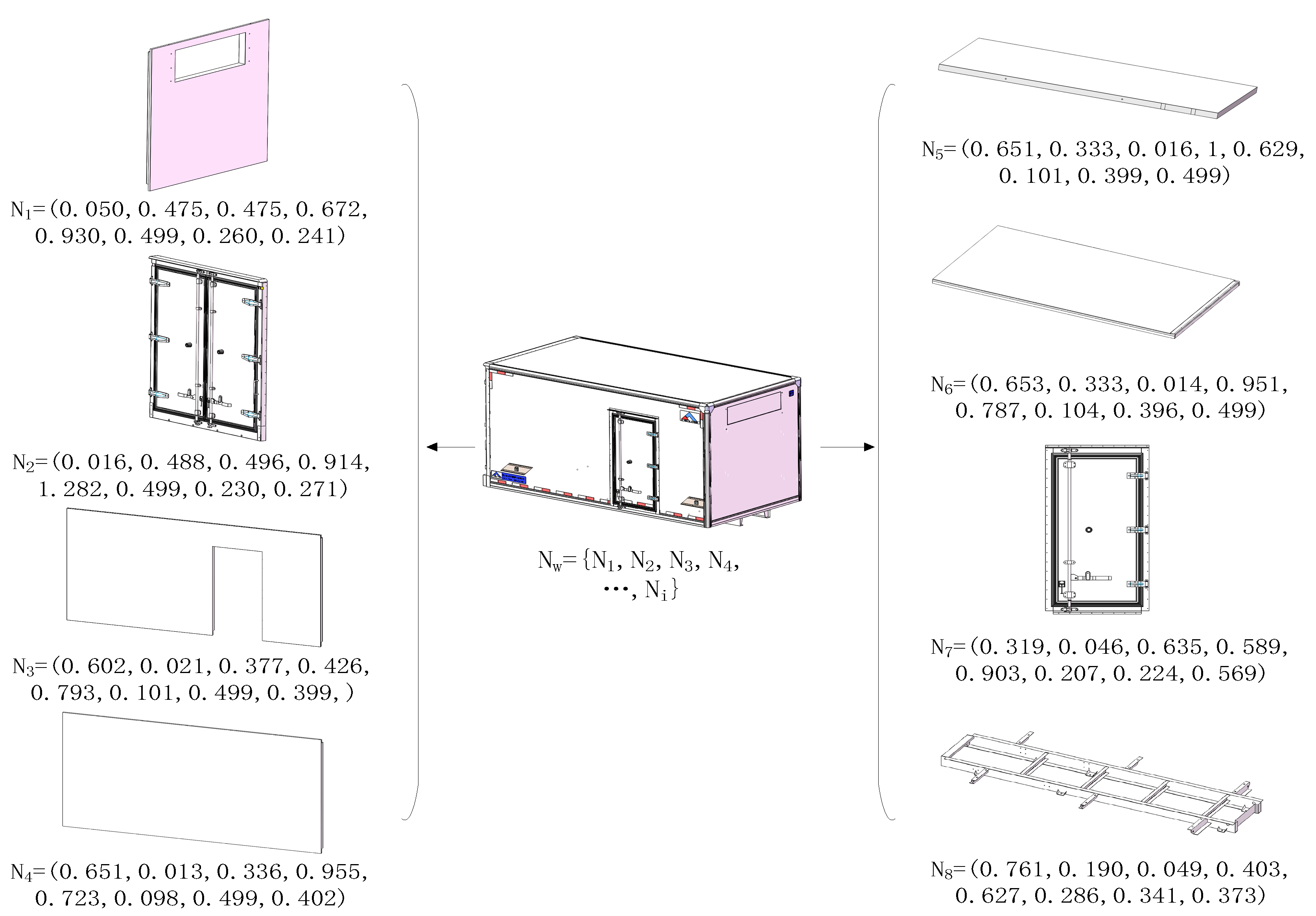
| Element Symbol | Model Name | Number | Vector Set Parameters |
|---|---|---|---|
| N1 | Foam | KF7.491 | (0.555, 0.330, 0.045, 0.110, 0.375, 0.520) |
| N2 | Outer Skin | KF9.652 | (0.645, 0.295, 0.005, 0.140, 0.505, 0.400) |
| N3 | Inner Skin | KF9.651 | (0.710, 0.250, 0.010, 0.520, 0.200, 0.265) |
| N4 | Framework | KF9.610 | (0.870, 0.060, 0.070, 0.020, 0.480, 0.485) |
| Element Symbol | Model Name | Number | Weight Value |
|---|---|---|---|
| N1 | Foam | KF7.491 | 0.438 |
| N2 | Outer Skin | KF9.652 | 0.273 |
| N3 | Inner Skin | KF9.651 | 0.209 |
| N4 | Framework | KF9.610 | 0.080 |
| Node | sim(MTZ,MiHZ), i = 1, 2, 3, 4… | ||||
|---|---|---|---|---|---|
| Foam | 0.912 | 0.896 | 0.878 | 0.863 | … |
| Outer Skin | 0.948 | 0.915 | 0.893 | 0.875 | … |
| Inner Skin | 0.921 | 0.898 | 0.864 | 0.847 | … |
| Framework | 0.870 | 0.903 | 0.889 | 0.856 | … |
| S(MT,MiH) | 0.9186 | 0.9020 | 0.8801 | 0.8621 | … |
| Dimension Number | Extract Name Information | Relevant Components |
|---|---|---|
| No.1 | D2@Sketch 8@Split Non-Independent Rear Inner Skin-1@Split Non-Independent Rear | Inner Skin |
| No.2 | D3@Sketch 8@Split Non-Independent Rear Inner Skin-1@Split Non-Independent Rear | Inner Skin |
| No.3 | D4@Sketch 8@Split Non-Independent Rear Inner Skin-1@Split Non-Independent Rear | Inner Skin |
| No.4 | D5@Sketch 8@Split Non-Independent Rear Inner Skin-1@Split Non-Independent Rear | Inner Skin |
| No.5 | D1@Sketch 1@Split Non-Independent Rear Outer Skin-1@Split Non-Independent Rear | Outer Skin |
| No.6 | D2@Sketch 1@Split Non-Independent Rear Outer Skin-1@Split Non-Independent Rear | Outer Skin |
| Target Model | Key Component Selection Results |
|---|---|
| Rear Wall Assembly | Inner Skin, Outer Skin, Foam Componen, Wooden Framework |
| Modle Name | Manual Annotation/min | Algorithmic Annotation/min | Efficiency Improvement Factor |
|---|---|---|---|
| Left Wall Foam Assembly | 6.03 | 0.79 | 7.6 |
| Left Wall Outer Skin | 5.13 | 0.68 | 7.5 |
| Left Wall Inner Skin | 4.87 | 0.62 | 7.8 |
| Left Wall Framework | 5.85 | 0.81 | 7.2 |
| Left Wall Assembly | 7.23 | 1.07 | 6.7 |
Disclaimer/Publisher’s Note: The statements, opinions and data contained in all publications are solely those of the individual author(s) and contributor(s) and not of MDPI and/or the editor(s). MDPI and/or the editor(s) disclaim responsibility for any injury to people or property resulting from any ideas, methods, instructions or products referred to in the content. |
© 2025 by the authors. Licensee MDPI, Basel, Switzerland. This article is an open access article distributed under the terms and conditions of the Creative Commons Attribution (CC BY) license (https://creativecommons.org/licenses/by/4.0/).
Share and Cite
Bai, Z.; Fang, X.; Feng, B.; Liu, Q. Intelligent Dimension Annotation in Engineering Drawings: A Case-Based Reasoning and MKD-ICP Algorithm Approach. Appl. Sci. 2025, 15, 5992. https://doi.org/10.3390/app15115992
Bai Z, Fang X, Feng B, Liu Q. Intelligent Dimension Annotation in Engineering Drawings: A Case-Based Reasoning and MKD-ICP Algorithm Approach. Applied Sciences. 2025; 15(11):5992. https://doi.org/10.3390/app15115992
Chicago/Turabian StyleBai, Zhengqing, Xifeng Fang, Bingyu Feng, and Qinghua Liu. 2025. "Intelligent Dimension Annotation in Engineering Drawings: A Case-Based Reasoning and MKD-ICP Algorithm Approach" Applied Sciences 15, no. 11: 5992. https://doi.org/10.3390/app15115992
APA StyleBai, Z., Fang, X., Feng, B., & Liu, Q. (2025). Intelligent Dimension Annotation in Engineering Drawings: A Case-Based Reasoning and MKD-ICP Algorithm Approach. Applied Sciences, 15(11), 5992. https://doi.org/10.3390/app15115992