1. Introduction
This paper proposes a hybrid energy storage system, combining supercapacitors with lead–acid accumulators, as a further step towards higher demands on efficient and adaptive energy storage. This hybrid approach [
1,
2] uses the complementary benefits of these two technologies [
3]: supercapacitors provide very fast charging/discharging capabilities with high power density, suitable for sudden surges in power demand. At the same time, accumulators ensure higher energy capacity for stable power supply over longer periods [
4,
5,
6]. Together, these form a very robust storage solution capable of handling steady-state and fluctuating power demands that are highly suitable for applications whose energy needs vary.
The novelty of this work is the design, implementation, and practical evaluation of a hybrid energy storage system [
7] that can optimally combine SC modules with lead–acid accumulators. Unlike previously used approaches, the system described herein includes an interconnect board that links the SC module with a bidirectional DC/DC converter [
8,
9,
10] and an accumulator to enable smooth transitions in power delivery [
11,
12] and real-time monitoring of system variables. The measurement circuitries are disposed on the interconnect board for precision monitoring of voltage and current, both for the SC module, accumulator, and converter for reliable systems management under diversified operating conditions. The originality of this paper is a practical implementation of HESS with a small power output and a bidirectional operation. Adding the SC module to the circuit with an accumulator significantly improves the current waveform from the accumulator regarding the lower ripple. This will dramatically extend the battery lifetime.
In
Section 2, the specific requirements of the SC module are detailed, together with the overall design of the hybrid system.
Section 3 extensively discusses the calculations and design of the SC module and the layout and features of the interconnect board.
Section 4 presents a control algorithm specifically designed for hybrid energy management applications that optimize the usage of SC modules for supplying high-current surges. In contrast, the accumulator can ensure continuous power delivery.
Section 5 is devoted to the experimental evaluation of the system with the proposed control algorithm from the results obtained in terms of current and voltage measurements at defined operating conditions. The introduced system proposes a new hybrid storage solution for energy management in applications demanding fast response and stable power delivery.
3. Design Procedure of the HESS
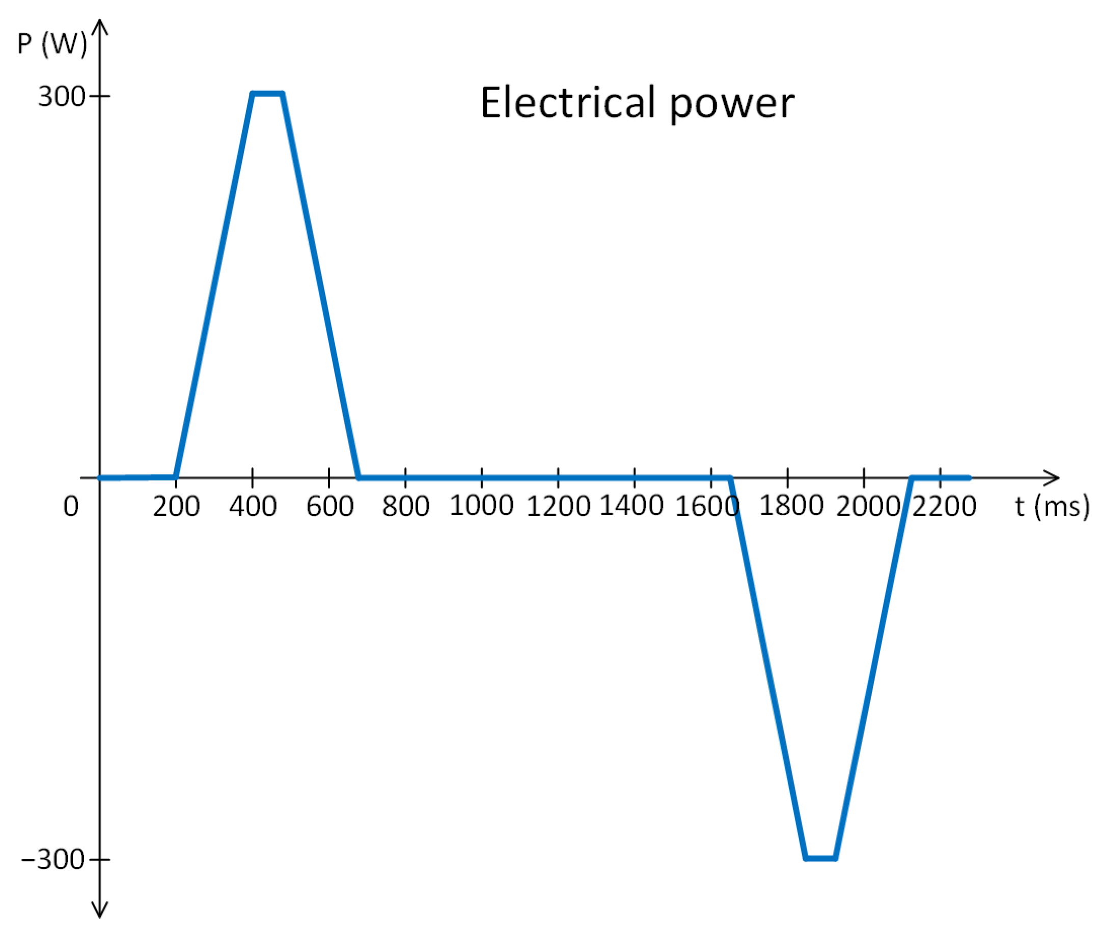
Based on the profile,
Figure 1, and the data from
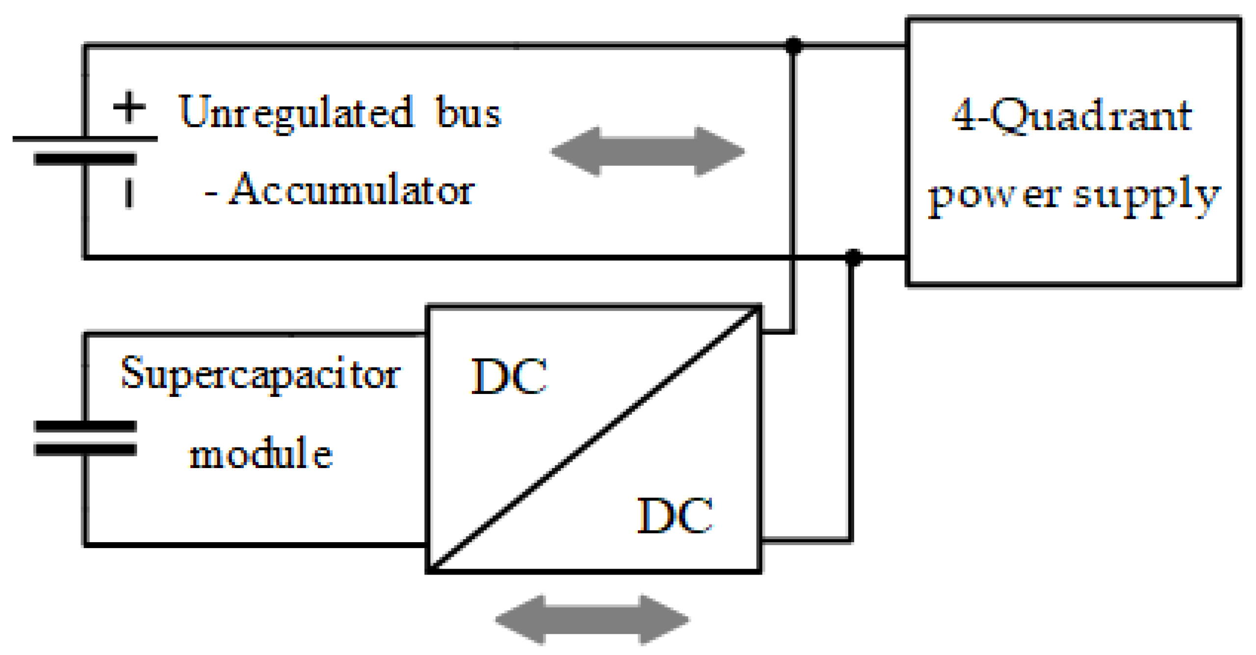
Table 1, the following concept,
Figure 2, of the HESS was designed.
In the laboratory setup, the four-quadrant power supply was used to simulate the SMPM motor drive, which is used in the practical scenario, but it was unavailable at the time of the system verification.
The next step in the design is calculating the minimum required SC module capacitance. The calculation of the SC module capacity is based on the energy criterion and power profile from
Figure 1. The area under the power profile is the required energy. For the simplicity of the calculation, it can be divided into two triangles and one rectangle. According to the general formula, the energy of the triangle and rectangle is given by Equations (1) and (2):
The total energy of the power profile in one direction is:
Primarily, the SC module was designed for a different profile. This profile had an energy
Ereq2 = 420 J. This part considered that the capacitor was discharged to 50% of its energy during operation. Therefore, the allowable energy of the SC module was doubled:
The value of the capacity, which allows storing energy of 840 J at a voltage of 13 V, is derived from the equation for calculation energy on the capacitor [
14] as follows:
Therefore, the SC module used for the mentioned profile is realized with a 10 F SC module. For the profile from
Figure 1, the expected minimum voltage and maximum current are recalculated using Equations (6) and (7):
Based on the calculations of the supercapacitors, the BCAP0010P270X01 was selected [
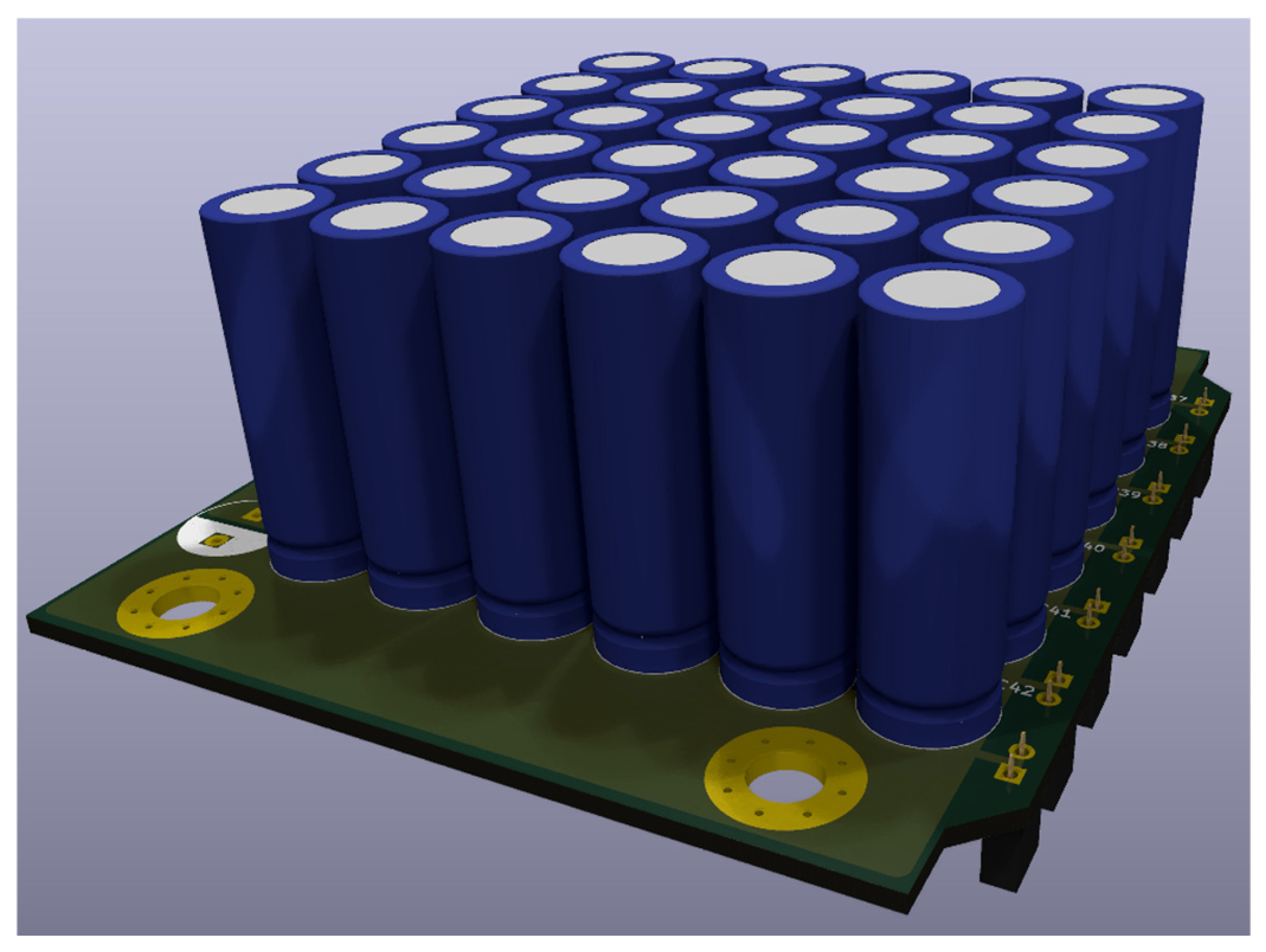
15]. Based on the datasheet rating and calculations, the 6S6P configuration was selected with the following parameters of the whole SC pack module. This configuration meets the requirements regarding capacity, maximum voltage, and maximum current. The parameters of the designed SC module are shown in
Table 2.
The configuration in
Figure 3 shows a 3D model of the designed SC module.
For rapid development purposes, the commercially available bidirectional interleaved DC/DC converter kit was used because it has all the required parameters for this application. The used evaluation board is Texas Instruments LM5170EVM-BIDIR (Dallas, TX, USA) [
16].
It is a dual interleaved bidirectional DC/DC converter with integrated control IC LM5170 (Dallas, TX, USA), which can be controlled in multiple ways [
17]. This controller provides current control of inductor currents. The parameters of the used converter are listed in
Table 3.
The SC module was connected to the boost side of the converter because the unregulated bus has voltages in the range of 20–34 V, and the SC module has a maximum working voltage of 13.5 V, so the voltage needs to be boosted. At the buck side, the load and unregulated bus were connected because if the load recuperates, the voltage needs to be stepped down to store energy in the SC module properly.
Because the eval board is universally designed by the manufacturer, the interconnecting board was designed to provide a power path to the SC module, unregulated bus, and load. Also, the control signals need to be wired to the eval board from the custom control board based on the C2000 DSP from Texas Instruments, where the control algorithm is executed. Because of the control algorithm, additional measurements and sensors must be added to the board to monitor voltages and currents properly. The following values are observed in
Table 4.
The interconnecting board was designed as a four-layer board with final dimensions of 158 × 153 mm.
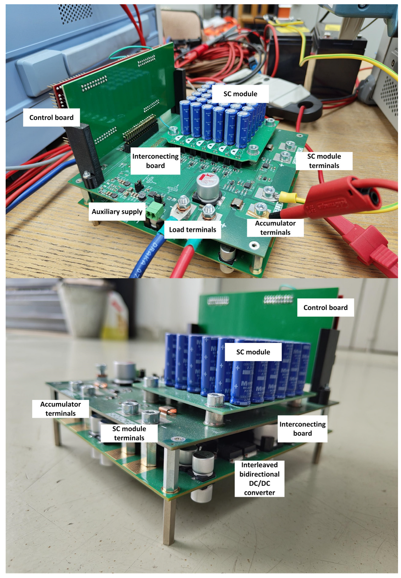
Figure 4 shows the final setup consisting of a DC/DC converter, an interconnecting board with an SC module, and a control board with a C2000 kit (Dallas, TX, USA).
The system comprises three interconnected boards, which manage energy flow between an accumulator, an SC module, and a load. The primary role of this system is efficient energy management and monitoring system variables. The PCB Stack-up consists of:
The interconnect PCB is placed between the control and DC/DC converter PCBs. Circuits placed on the board monitor critical electrical parameters such as currents, voltages, and individual supercapacitor cell voltages. Subcircuits are:
Input port for an unregulated bus (accumulator)—This port connects to the main power source, in this case, the accumulator, which provides a limited amount of current. This port also serves as a measuring point for the unregulated bus voltage and is shared with the buck side of the bidirectional DC/DC converter.
Port for the load—This port connects the load to the system. Because the load can sink and source power, the current measurement is designed to be bidirectional. Voltage is also measured to calculate the load power.
Input port for the SC module—This port connects the SC module with the boost side of the bidirectional DC/DC converter. This port also monitors the voltage and current of the SC module. Current measurement is also designed as bidirectional.
Measurement and auxiliary circuits—This board is also populated with another measurement circuit for monitoring individual cell voltages to implement an overvoltage protection of the supercapacitor cell, which is susceptible to overvoltage conditions. The connector for the control board is also populated on this board, together with the auxiliary power supply, which provides the necessary voltages for the measurement and control circuits.
The bidirectional DC/DC converter board, located beneath the interconnect board, contains all the power circuits necessary for the bidirectional power transfer between the load and SC module. The control board controls this module.
The control board, located at the top of the interconnect board, is responsible for the operation of the bidirectional converter and is based on the C2000 real-time DSP, specifically TMS320F28069M (Dallas, TX, USA). Measurements are made on this DSP, which are then fed to the control loops, explained later in this paper. A communication interface is also present to communicate with the PC or send the data.
4. System Control Algorithm
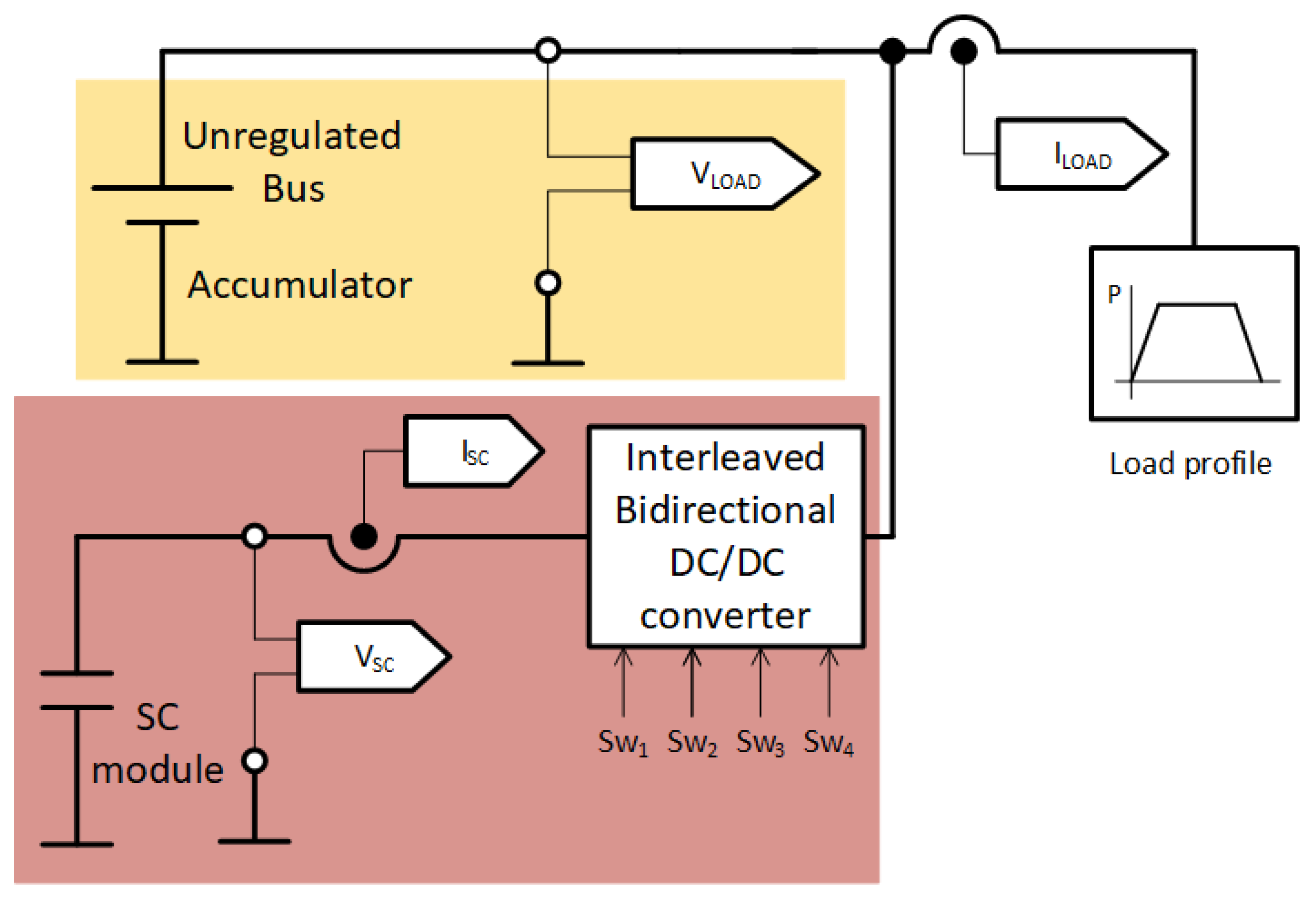
Figure 5 depicts the electrical connection of the proposed system. The main source of energy is an accumulator. There is no requirement to maintain a constant voltage on the given accumulator, so this source is designated as an unregulated bus. The designed SC module represents the additional energy source of the hybrid energy system. The load voltage (accumulator voltage), load current, SC module current, and voltage were measured to regulate the system. The DSP measures voltages and currents in the system. Based on the values, power is calculated, and then, based on the load power direction, a specific operation mode is selected, as shown in
Figure 6. The bidirectional converter current is controlled by the PWM output of the DSP.
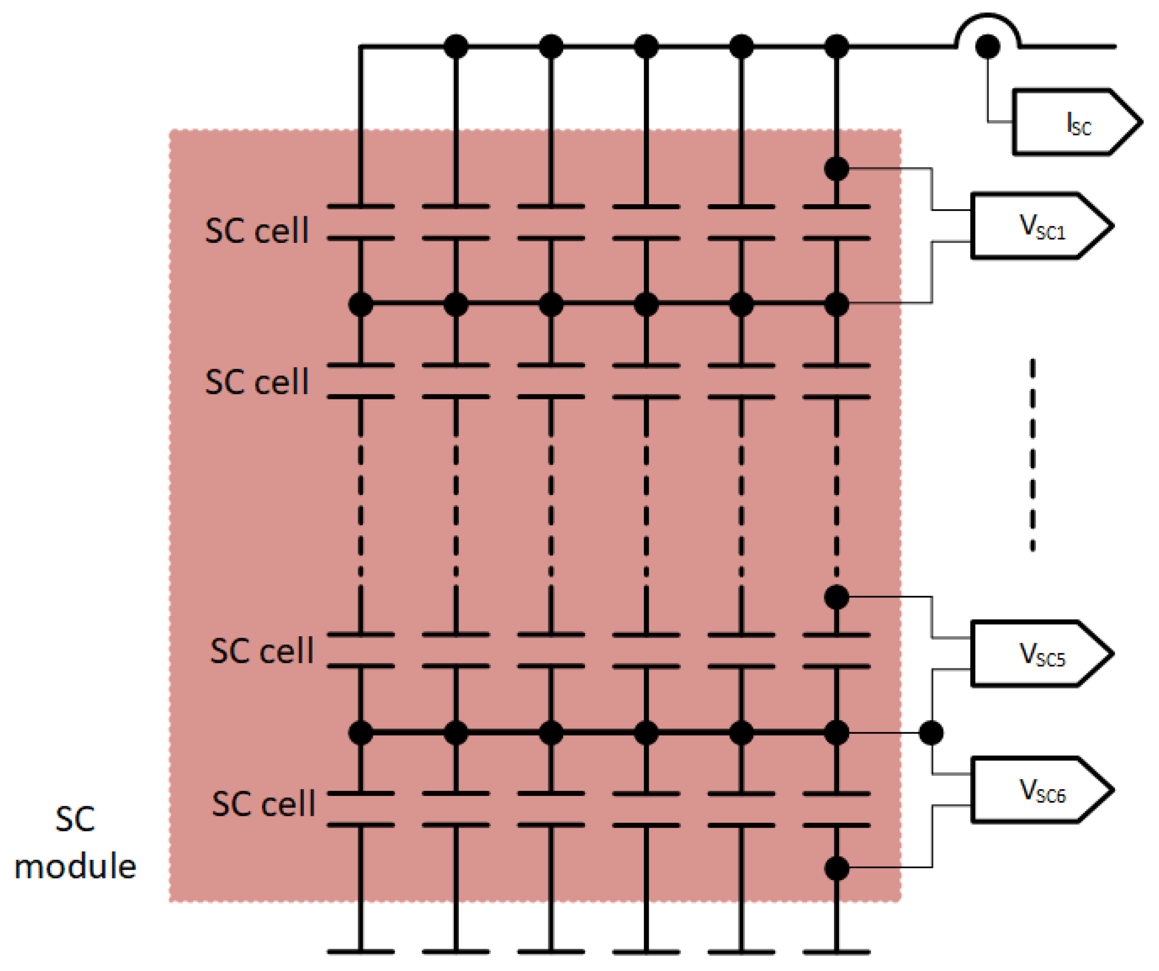
Figure 7 shows the block scheme of the SC module. Six SC modules are connected in series and six in parallel. Each parallel branch contains a voltage measurement. Therefore, it is possible to measure/observe the voltage distribution on individual branches. The sum of all voltages gives the voltage of the entire SC module. The current measurement from the SC module is connected to the positive clamp.
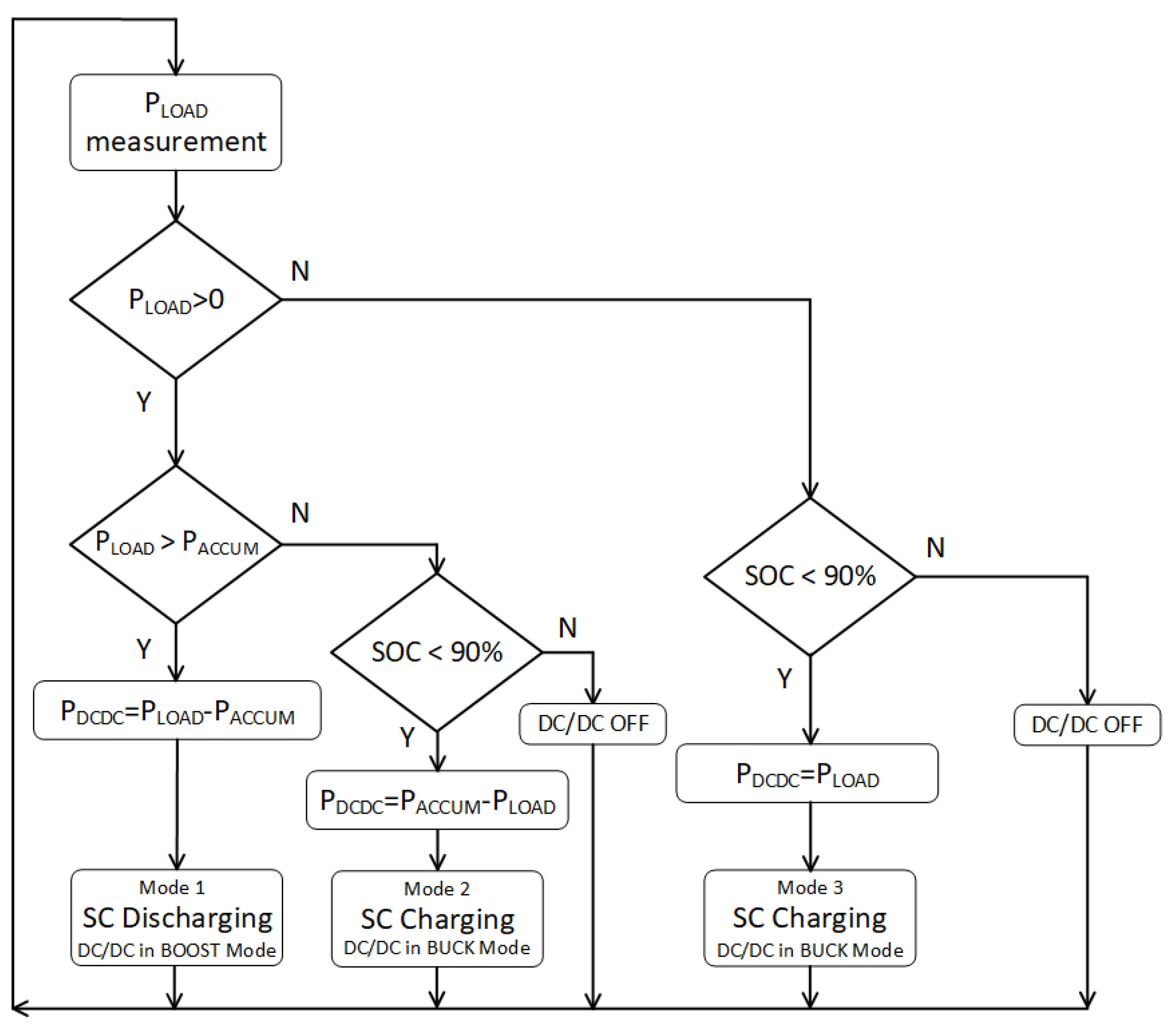
The control of the bidirectional DC/DC converter is divided into three modes, shown in
Figure 6. Two of them mean the operation of the converter is in buck mode, and one is in boost mode. The basic principle of the control algorithm is to deliver average power from the accumulator and residual power from the SC module to the load.
The control algorithm is dependent on the load power measurement. The load power is calculated based on the battery voltage VLOAD since the DC bus is common, and the load current ILOAD. If the load power is positive, the load is a consumption device. Another important decisive parameter is the supplied power from the accumulator PACCUM, which is selectable/adjustable. If the power of the load PLOAD is greater than the adjustable power from the accumulator PACCUM, then the differential power is supplied from the SC module, and the inverter works in Mode 1. If the load power is less than the allowable power from the accumulator and at the same time the SOC level of the SC module is less than 90%, then the SC module is recharged with the remaining power from the battery, and thus, the bidirectional converter is in Mode 2. If the SC module is charged (SOC > 90%), then the bidirectional converter is switched off, and only the required power PLOAD flows from the accumulator. If the load power PLOAD is negative, the load becomes a source, and all power is supplied to the SC module as long as the SOC is less than 90%. If the SOC of the SC module reaches 90%, the entire recovered power flows into the accumulator, and the bidirectional converter is disabled.
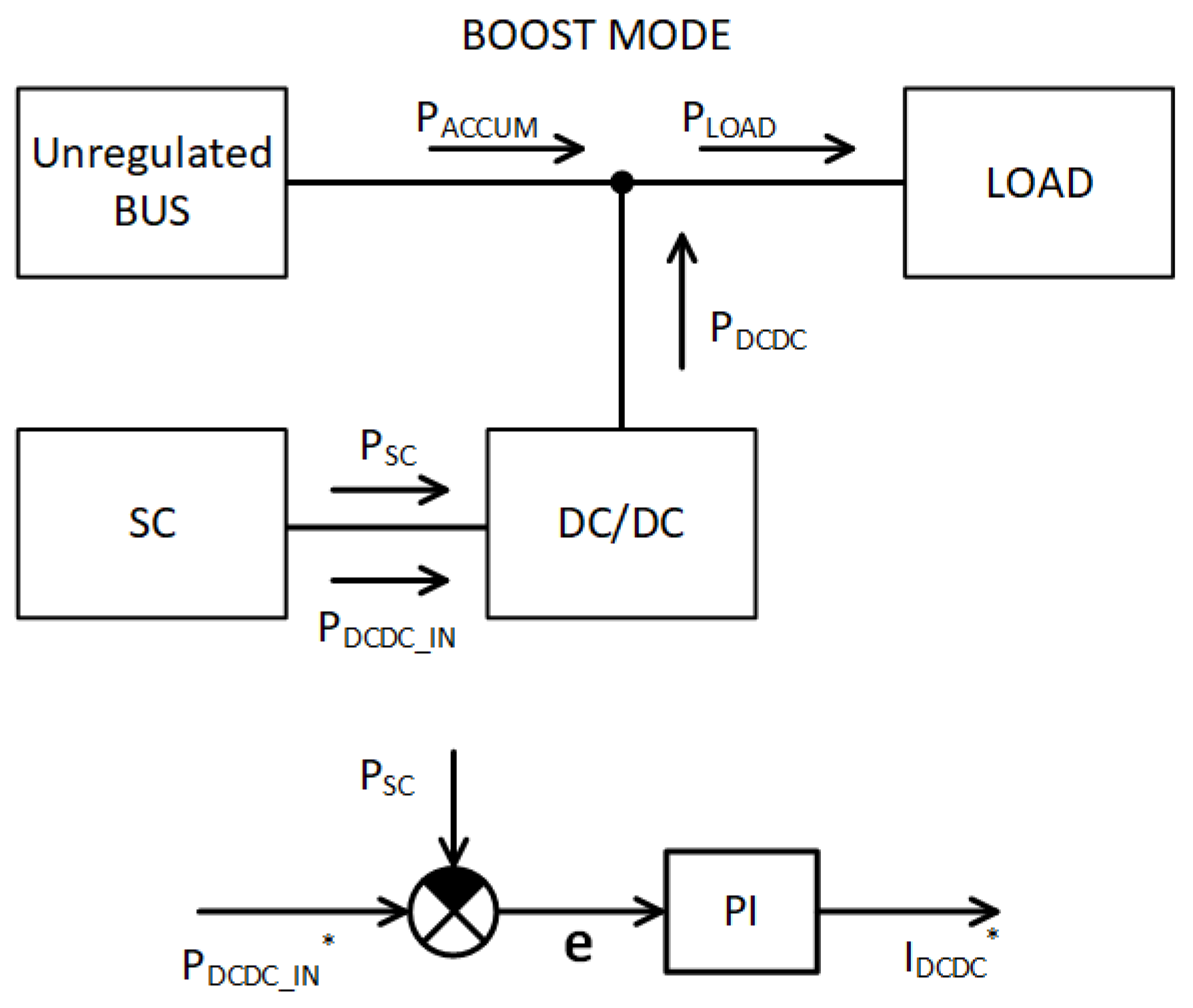
The accumulator power value is optional, and then the SC module power is calculated as the difference between load and accumulator power; see Equation (8). The basic scheme of the control algorithm for the boost mode is depicted in
Figure 8. The problem is that the current at the output of the DC/DC converter is not measured, so it is impossible to determine the power of the
PDCDC directly. The
PDCDC power represents the output power of the bidirectional DC/DC converter. However, only the voltage and current of the SC module are measured, which represents the SC module/input power of the DC/DC converter
PDCDC_IN or
PSC. Therefore, the output power of the converter is converted to input power
PDCDC_IN using the measured efficiency characteristic of the converter in boost mode. This value is also understood as the desired power value
PDCDC_IN*; see Equation (9). Then, the desired
PDCDC_IN* power is compared to the measured input/SC module power
PSC. The regulation error enters the PI controller, whose output is the desired current
IDCDC*, which enters the internal current loop of the inverter. Then, the output of the internal current loop is the desired duty cycle value. The equations for calculating power components are as follows:
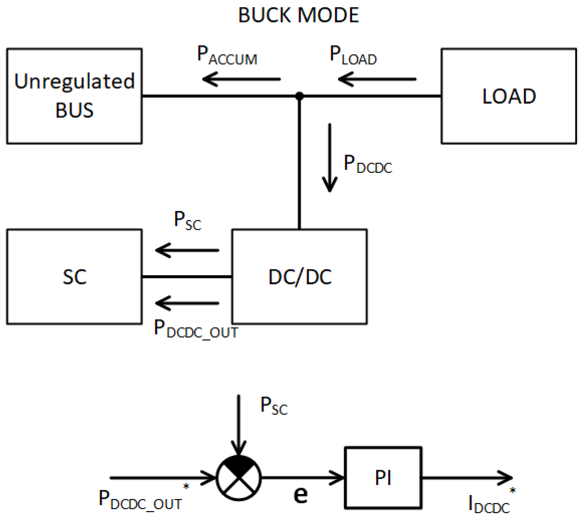
The bidirectional converter operates in buck mode when the load power PLOAD is smaller than the allowable power PACCUM (Mode 2) or less than zero (Mode 3).
Mode 2 also charges the SC module, but the difference is that it is charged from the accumulator, not the load. The block scheme of the algorithm is shown in
Figure 9, and equations for calculating the desired value of SC module power
PDCDC_OUT* are given in Equations (11) and (12):
In Mode 3, the direction of the load power PLOAD has changed, and thus, the direction of the accumulator and SC module power (PACCUM and PDCDC_OUT or PSC) has also changed, as is seen in
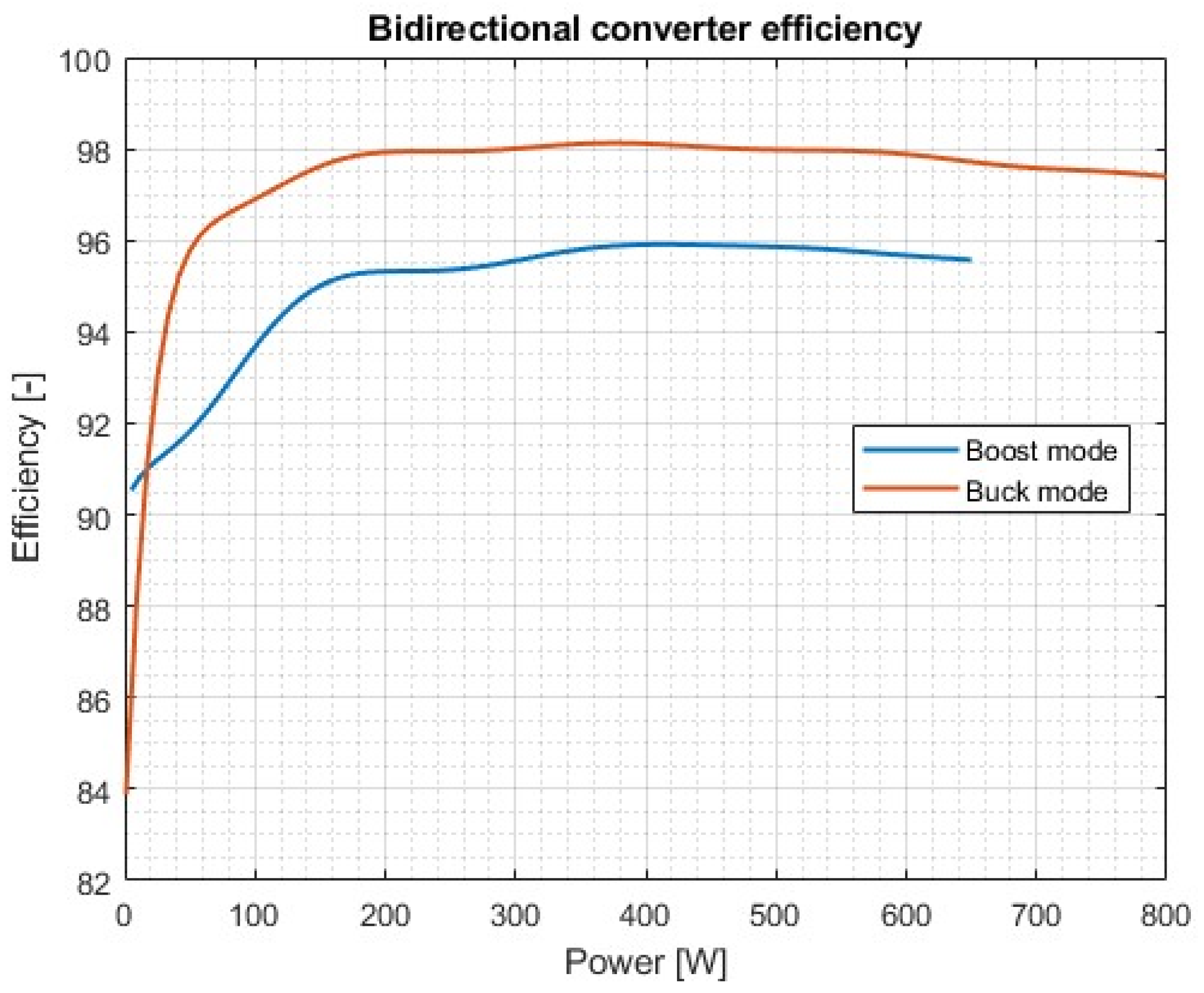
Figure 10. As in boost mode, here in buck mode, it is impossible to determine the power of PDCDC directly; therefore, it is recalculated using the efficiency characteristic of the buck converter. These statements are shown in Equations (13) and (14), and efficiency characteristics are shown in
Figure 11:
Figure 11 shows the converter efficiency in both modes of operation. These values were imported as a one-dimensional array to the DSP and used as the calculation parameter of the bidirectional converter power.
5. Experimental Results
For the experimental setup, the required load profile must be imported into the source in one direction and into the load in the opposite direction. For this scenario, a four-quadrant power supply was used to sink and source power. In this power supply, the load profile was programmed to reflect the proposed profile shown in
Figure 1. Firstly, the constants of the PI regulators were tuned to obtain the proper response of the system. This experiment used a lead–acid 24 V accumulator to substitute the unregulated bus accumulator. The advantage of a lead–acid accumulator is that it can be charged, so the operation where power is delivered from the load to the SC module and the accumulator simultaneously can be tested. The testing plan was divided into several sections:
Testing of the SC module. The procedure involved inspecting the accuracy of the measured signal and subsequently verifying the even distribution of voltages on the individual cells of the SC module.
Testing the DC/DC converter in a supply mode to the load. The primary goal was the verification of a full-power operation in boost mode.
Testing of the DC/DC converter in a recovery energy mode. The primary goal was the verification of a full-power operation in buck mode.
Testing bidirectional mode with a designed SC module and parallel-connected 24 V accumulator.
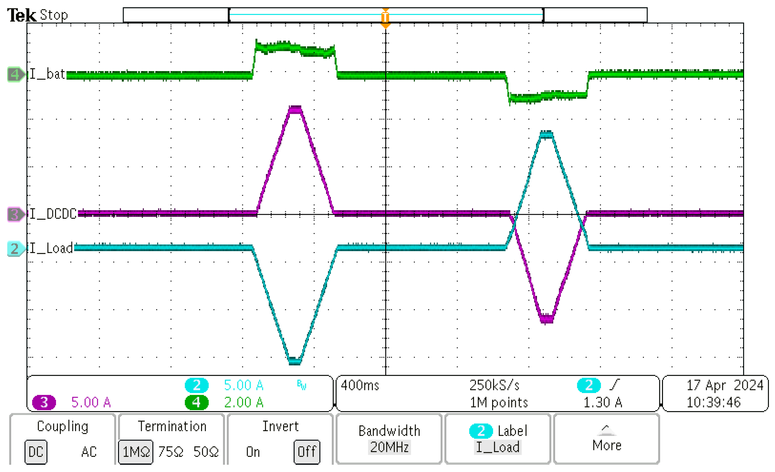
Figure 12 shows the results of the measurement for scenario 1. The profile is divided into two sections. The first section is when the load is sinking power. It represents the negative value of the load current
I_Load (blue waveform). In this section, the accumulator provides a nearly constant output current
I_bat of 1 A (green waveform) as set in the control algorithm, and the remaining current
I_DCDC is supplied from the SC module and bidirectional DC/DC converter. In section 2, when the load is sourcing power, the accumulator is charged with a value of current 1 A, and the remaining current flows through the DC/DC converter to the SC module (magenta waveform). The load voltage is identical to the unregulated bus voltage, which is 24 V.
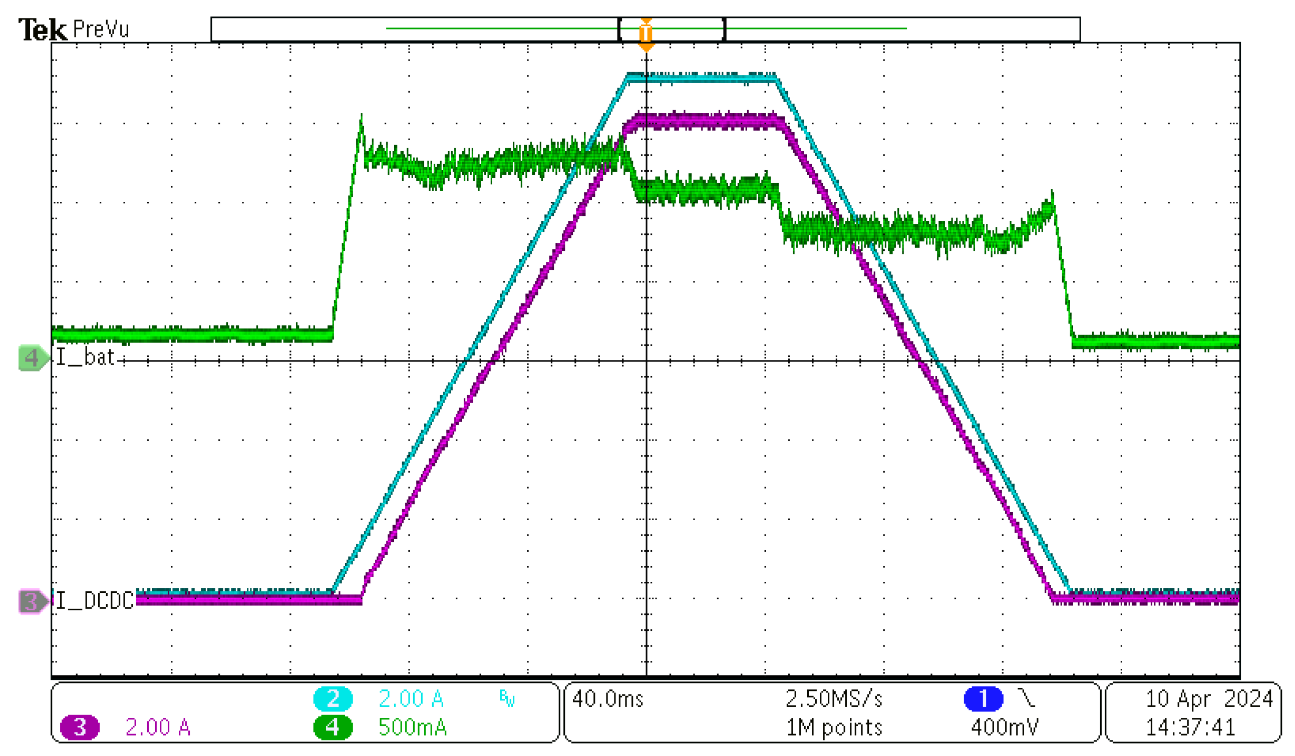
In the other case, when the load is sourcing current/power (blue waveform in
Figure 13) is positive, the current is delivered to the SC module to recharge it and to the unregulated bus. In this scenario, the accumulator current was set to 1 A, and as can be seen, the accumulator was charging with a constant current of 1 A. The detailed waveform in
Figure 13 shows the regulator response to the load waveform in detail.
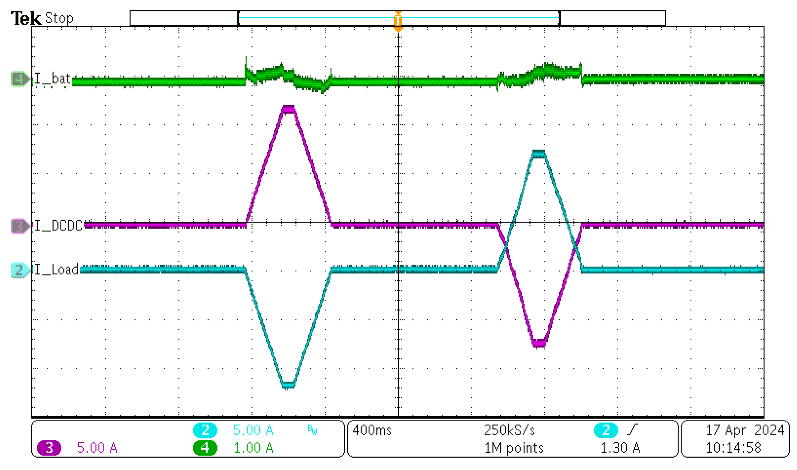
In the second experiment,
Figure 14, the unregulated bus current was set to 0 A in both scenarios, where the load is sinking and sourcing power. This means the whole power to the load is delivered from the SC module, and during the recuperation, the entire power is used to charge the SC module. The results from the measurement can be seen in the following figure:
The green waveform shows that the accumulator current is nearly zero. The entire power flows from and to the SC module. As mentioned, the internal variables at the distribution board were also monitored. The system sampling frequency is 2 kHz and can simultaneously log four variables.
Figure 15 shows the SC module voltage and current in the scenario, where the accumulator current was set to 0 A in both ways.
As can be seen, the initial SC module voltage was 13 V (blue waveform). The load is sinking current from time 4.5 s to 5 s, and the SC module is discharged. The peak current during this operation is 25 A. After the discharge cycle, the steady-state voltage is 12.3 V, which confirms the results calculated in Equations (6) and (7). In the second cycle, where the load is sourcing power, the SC module is charged. The peak current is around 22 A, and the SC module is charged from 12.3 V to 12.9 V. The lower value of the SC module voltage at the end of the second cycle reflects losses in the system, mainly in the bidirectional DC/DC converter.
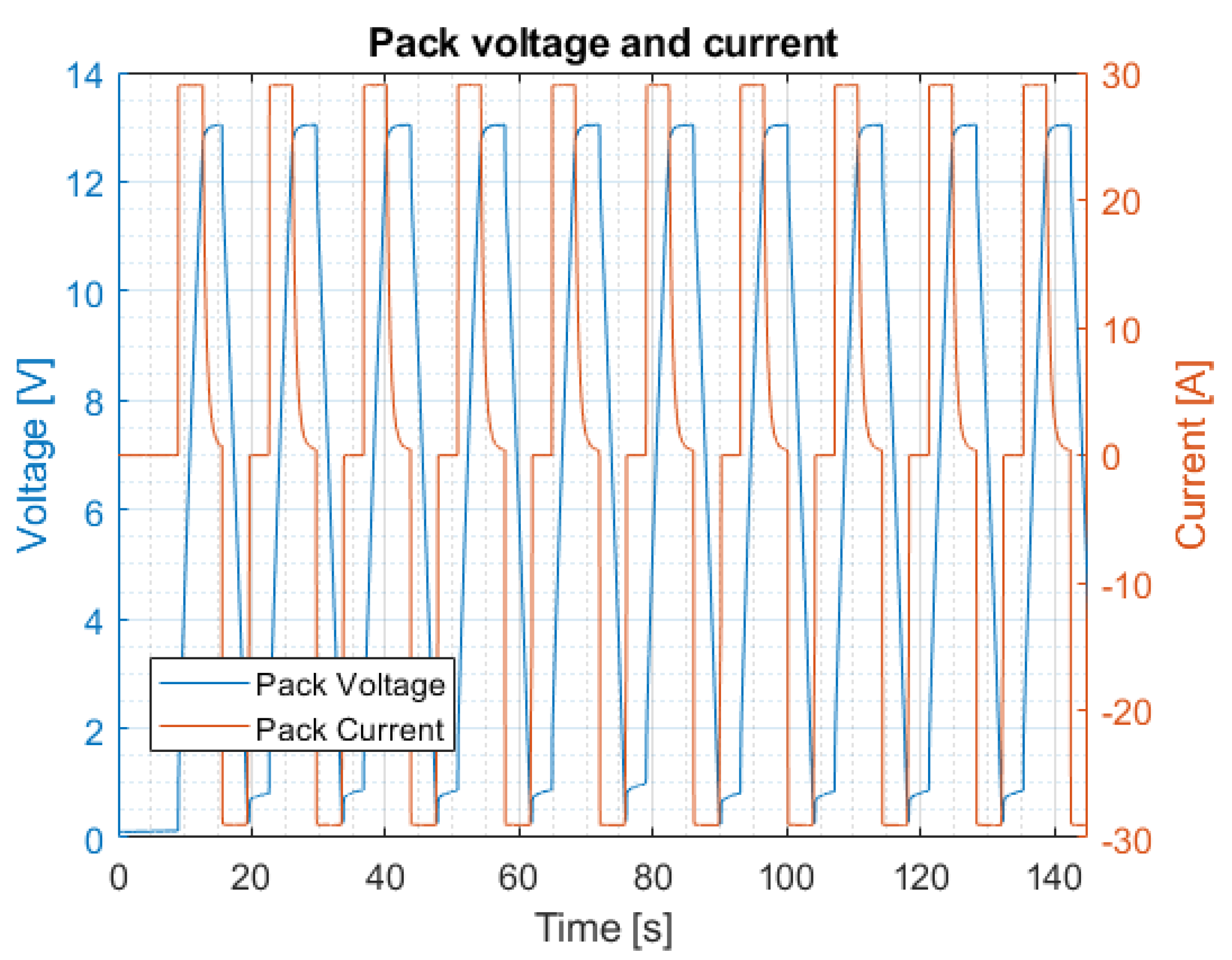
To properly test the SC module, it was constantly charged and discharged with a current of 30 A to monitor the cell balance. Cell balance is the most important factor in series-connected cells because if the cell voltage drifts during cycles, the weaker cells can be damaged by the overvoltage condition. The test was performed for 150 s (10 periods of operation), during which time, cell voltages and temperature were monitored. The pack voltage and current can be seen in
Figure 16.
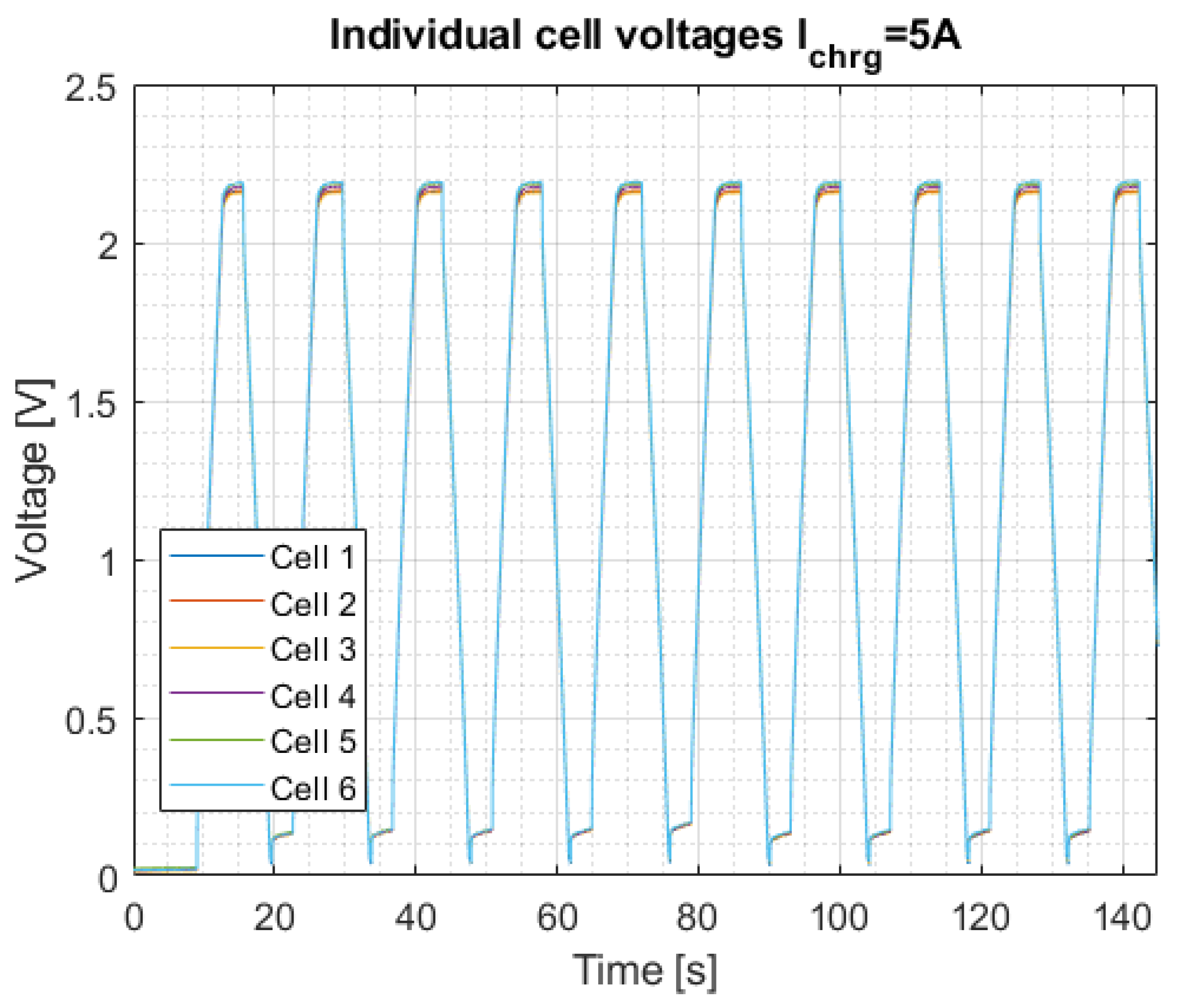
The SC module was constantly charged and discharged from around 1.5 V to 13 V, with a current of 30 A. Individual cell voltages can be seen in
Figure 17.
The I
chrg = 5 A is relevant to the one-cell series group. Because the pack has six series groups, the total charging current of the pack is 30 A, as shown in
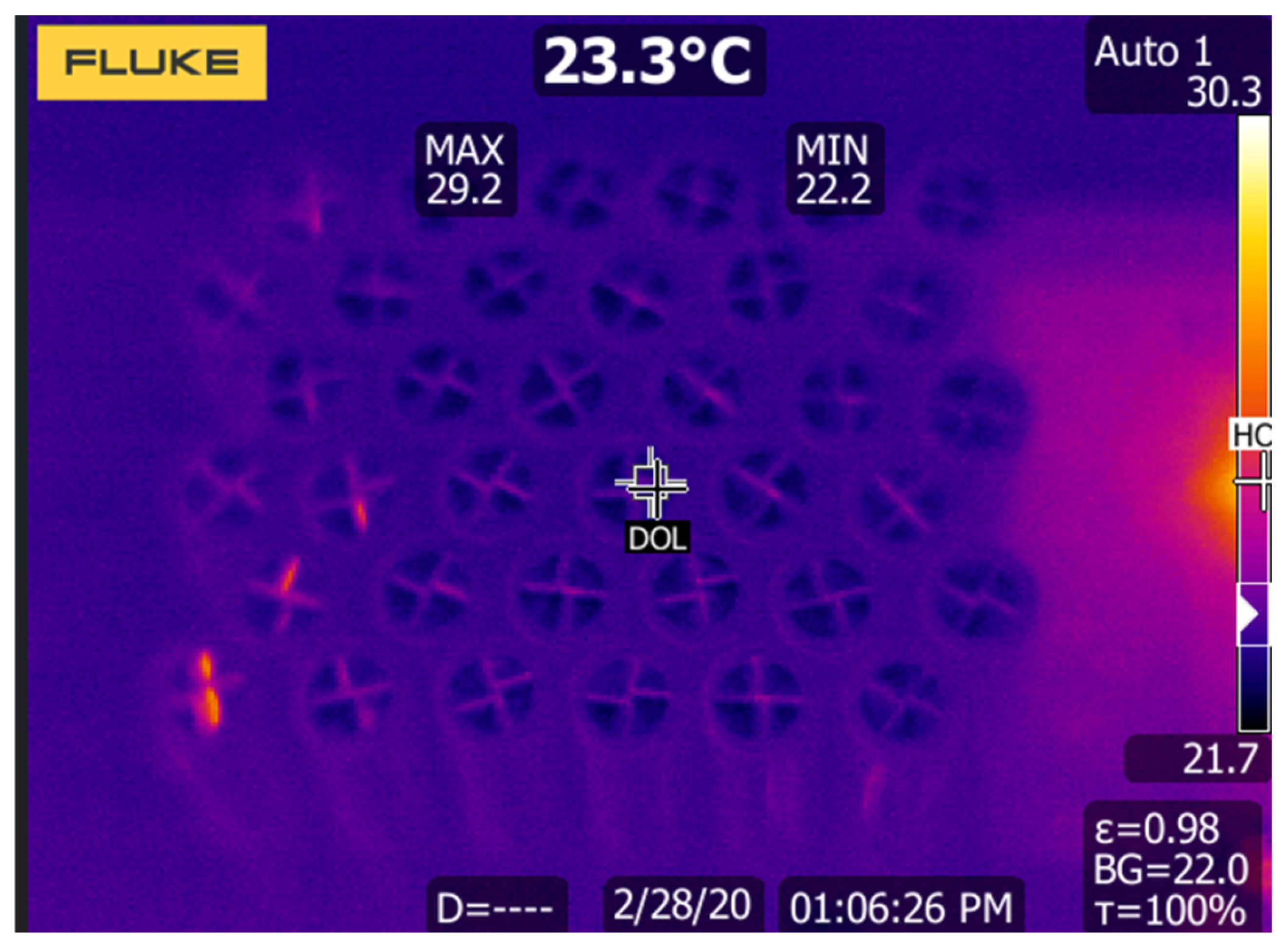
Figure 16. As can be seen, the cell balancing is excellent, and individual cell voltages are not drifting from each other. This proves a good match for the supercapacitors. Finally, the temperature of the module was monitored. The following
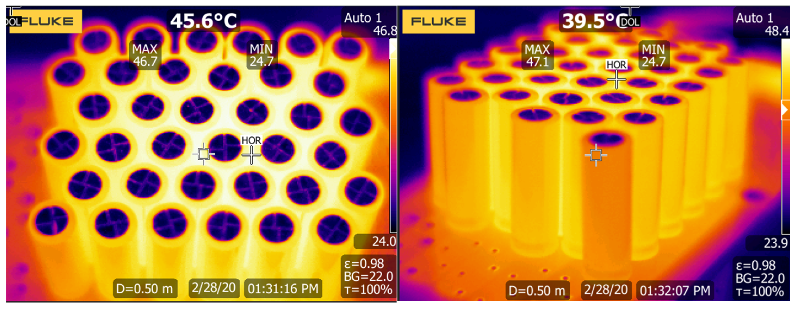
Figure 18 shows the temperature before the cycle measurement.
The average temperature is around 25 °C before the test. After the test, the maximum temperature reached 47 °C, which is within the tolerance provided by the manufacturer; see
Figure 19. This temperature rise is mainly caused by the internal ESR of the supercapacitors and the fact that a current of around 30 A was flowing through the module. The average power loss in the SC module was around 11 W. This experiment was designed to measure the absolute limit of the developed modules. In practical application, the modules will not be cycled so often.
6. Conclusions
This paper presents the design of a power system using a HESS with an SC module and a bidirectional converter to deliver the required power according to the load requirements. The DSP controls the presented system, which offers much flexibility in this application. The SC module was calculated and designed according to the specifications with a final capacitance of 10 F. After selecting the bidirectional DC/DC converter, the interconnect board was designed to properly connect the DC/DC converter, SC module, accumulator, and load. The measurement circuits were added to this board to monitor all required parameters. Finally, the presented setup was verified in the practical scenario with the help of the four-quadrant power supply simulating sink/source load. The measurement results clearly show that the proposed solution works perfectly and meets all the required criteria of the application. The dynamic test of the SC module shows a small amount of heat generated, but this test was designed to test the thermal limits of the module, and these conditions never arise in practical applications.
One possible improvement is increasing the number of series supercapacitors to increase the overall SC module voltage. This results in a lower current through the SC module and the DC/DC converter. This leads to lower conduction losses, thus improving efficiency. This step leads to higher SC module prices at the expense of slightly enhanced efficiency. The improved control algorithm can use progressive decision techniques to store and deliver energy stored in the SC module properly. This can lead to optimal energy storage and its availability in different scenarios.
Future work will focus on verifying this concept with the final profile using the SMPM drive, which can dynamically sink or source power based on external conditions.


