Abstract
In recent years, there has been a significant amount of research on tiltrotor multicopter unmanned aerial vehicles (TM-UAVs) in aerial robotics. Despite the varying frame types of TM-UAVs, they all still aim to decouple the propeller from the body, which means that the propeller’s attitude control is independent of the body’s attitude control. On the one hand, this solves the issue of multicopter unmanned aerial vehicles (M-UAVs) being limited by small roll and pitch angles, thereby improving flight performance. On the other hand, it addresses the drawbacks of M-UAVs as typical underactuated systems. However, the fact still remains that it cannot significantly change thrust direction, thus providing the necessary wrench direction for aerial manipulation. This paper presents a pitch-axis tiltrotor quadcopter unmanned aerial vehicle (UAV) design named Tilt-X, which can maximize horizontal pulling force and yaw moment when used as an aerial manipulator. This design contributes to tasks such as pushing, pulling, and twisting. The reliability of the design has been demonstrated through dynamic modeling and experimental validation.
1. Introduction
This section includes the research motivation and reveals the shortcomings of the state-of-the-art (SOTA), leading to the proposal of a novel TM-UAV design.
1.1. Motivation
Multicopter unmanned aerial vehicles (M-UAVs) utilize multiple propellers to provide thrust perpendicular to the direction of the body, enabling vertical takeoff and landing (VTOL). Horizontal movement is not directly driven by the thrust of the propellers but is achieved by tilting the body to change the direction of the propeller thrust. There is a similar issue with yaw motion, which is achieved through the moment difference between propellers rotating in opposite directions. This incomplete actuation results in low efficiency in horizontal flight and yaw motion. A tiltrotor quadcopter unmanned aerial vehicle (UAV) named TJ-FlyingFish has addressed these issues through experiments in water []. Water is a higher resistance medium compared to air and amplifies the disadvantages of the quadcopter as an underactuated system. Therefore, the wrench that M-UAVs can apply to the environment is limited. The main reason for these deficiencies in M-UAVs is the coupling between the propellers and the body. Excessive body attitude angles affect stability, necessitating limiting the propeller’s attitude. Thus, research on tiltrotor multicopter unmanned aerial vehicles (TM-UAVs), which aims to decouple the propellers from the body, has gradually emerged.
1.2. State of the Art
TM-UAVs can be categorized into fixed TM-UAVs and variable TM-UAVs. The fixed TM-UAVs have an inclined surface that is installed at the ends of the cantilever arms, thereby they can tilt the propellers. For example, the Hex-rotor’s inclined surfaces are not parallel so that it resists wind gusts more efficiently [], and the Tilt-Hex supports horizontal flight and maintains a level attitude []. Another design is to mount the propellers on inclined cantilever arms, such as the omnidirectional aerial vehicle [], which has an eight-rotor configuration that maximizes the vehicle’s agility in any direction, possessing full force and moment authority in all three dimensions. Variable TM-UAVs can be divided further into two types of mechanisms: those with specific mechanisms and those with additional servomotors to tilt the propellers. An example of the former is the Gemini II bi-copter [], which controls attitude by using a cyclic flapping response in hinges that connect the blades. The -multirotor combines the advantages of both specific mechanisms and additional servomotors by using two servomotors to create a universal joint connecting the propeller part and the body part, transforming the quadcopter from an underactuated system into a fully actuated system []. The TM-UAVs with additional servomotors are usually overactuated systems. Although they increase battery consumption, their contribution to fully actuated motion makes them meaningful. For example, the Gemini bi-copter utilizes two servomotors for yaw and roll control []. Using servomotors for yaw motion is more efficient, as the torsion originally produced by the moment difference between counter-rotating propellers is directly provided by the horizontal component of the propeller thrust. A classic example of a tiltrotor quadcopter is the Holocopter, designed for actuated flight in both the roll and pitch axes []. The Fast-Hex tiltrotor hexacopter is another example, converting an underactuated system into a fully actuated system []. The tiltrotor omnidirectional micro-aerial vehicle (OMAV) can exert a wrench in any orientation while maintaining efficient flight configurations []. Besides TM-UAVs, there are also foldable M-UAVs, aimed at reducing size for navigating through tight spaces, such as the foldable drone [] and the midair reconfigurable quadcopter [].
As an extension of M-UAV research, aerial physical interaction (APhI) involves interactions in the vertical plane, curved surfaces, and horizontal plane. Research related to vertical plane interactions includes brushing for cleaning [], installing a sensor on a tree [], moving the manipulator on the surface of a glass wall [], performing an ‘aerial-writing’ task [], and performing a cleaning operation on a vertical surface []. These tasks share the commonality of being achieved through a fixed manipulator, as the vertical movement of M-UAVs is directly driven by the thrust of the propellers, making vertical plane interactions feasible. Research related to curved surface interactions includes cleaning an exhaust shaft [], rolling along a curved surface [], and force feedback control []. The design of TM-UAVs allows them to interact beyond flat surfaces. Research related to horizontal interactions includes pulling a drawer knob [], pushing a rolling cart and hinged door [], and extracting a wedged object []. However, the wrench in the horizontal direction is underactuated for M-UAVs. To address the potential issues of insufficient pulling and push force, the degrees of freedom (DOF) for these manipulators are three, two, and two, respectively. Another solution is to achieve horizontal interactions by tilting the propellers while still using a fixed manipulator, such as pushing a cart in an uncertain environment []. This approach’s advantage is that it only considers the TM-UAV system itself. Similarly, when performing aerial torsional tasks, such as turning valves [,], there may be insufficient torsion since the yaw motion of M-UAVs is also not fully actuated.
1.3. Contribution
Regarding the TM-UAVs in performing APhI tasks such as aerial horizontal interaction, the paper on the Tilt-Hex [] claimes that a fixed TM-UAV has a laterally bounded force capability, and research on the omnidirectional aerial vehicle [] mentions that it possesses full force and torque controllability in all three dimensions, while the paper on the tiltrotor OMAV [] explains that a variable TM-UAV can exert omnidirectional wrench on the environment. However, considering the torque and power of the actuators used, the horizontal pulling force could be further maximized. This limitation arises because not all propellers can tilt in the same direction. Other TM-UAVs face similar constraints. Additionally, fixed TM-UAVs struggle to adjust the magnitude of horizontal pulling force while hovering, indicating that merely changing the thrust force of the propellers without altering their tilt angle is insufficient. Therefore, it is evident that TM-UAVs should be capable of tilting all propellers in the same direction to maximize horizontal pulling force.
Therefore, to address the issue of insufficient horizontal pulling force of M-UAVs as aerial manipulators, this paper proposes a design for an aerial robotics system featuring a tiltrotor quadcopter UAV, named Tilt-X, as shown in Figure 1. As shown in Figure 1a, since the M-UAVs have under-actuation properties, they find it difficult to exert a horizontal pulling force on the environment, making it hard to separate an attached object from the wall. The proposed Tilt-X is designed to be suitable for performing aerial horizontal interactions. Thus, it can exert a maximized horizontal pulling force on the environment, as shown in Figure 1b, by tilting all propellers in the same direction backward from a wall. In addition, it is also suitable for performing aerial torsional interactions. It can maximize vertical torsional wrench, i.e., yaw moment. While the underactuated M-UAVs find it challenging to exert a large vertical torsional wrench, making it difficult to turn a valve, as shown in Figure 1c, the proposed Tilt-X can generate a bigger yaw moment to turn the valve by tilting two pairs of propellers symmetrically in opposite directions, as illustrated in Figure 1d.
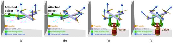
Figure 1.
APhI tasks such as aerial horizontal interaction and aerial torsional interaction. (a) A M-UAV may be unable to separate an attached object from the wall due to insufficient horizontal pulling force. (b) Tilt-X can separate an attached object from the wall since tilting propellers maximize the horizontal pulling force. (c) A M-UAV may be unable to turn the valve due to insufficient yaw moment. (d) Tilt-X can turn the valve since tilting propellers maximize the yaw moment.
2. Modeling
This Section describes the mathematical models of Tilt-X, providing the theoretical basis for the experiments presented in Section 3.
2.1. Definition
2.1.1. Assumption
- The cantilever arms of Tilt-X are rigid body;
- The mass and moments of inertia of Tilt-X are constant;
- The geometric center and the center of gravity (COG) of Tilt-X are the same.
2.1.2. Notation
For ease of reading, the definitions of all symbols mentioned in this paper are shown in Table 1.

Table 1.
Definitions of all symbols.
2.2. Kinematics
2.2.1. Kinematic Model
The body coordinate frame (BCF) of Tilt-X, consisting of , and the earth coordinate frame (ECF), consisting of , are shown in Figure 2a; the origin coincides with the COG. For the attitude angles, roll is the rotation of the body around the x-axis, denoted by , pitch is the rotation of the body around the y-axis, denoted by , and yaw is the rotation of the body around the z-axis, denoted by . The distance from each propeller to is d.
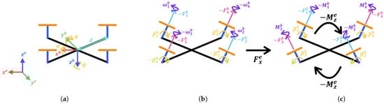
Figure 2.
(a) Coordinate systems BCF and ECF, and the attitude angles , , and . Two ways of tilting propellers to maximize (b) the horizontal pulling force by tilting propellers 1 to 4 in the same direction, and (c) the yaw moment by tilting propellers 1 and 4, and propellers 2 and 3 in opposite directions, respectively.
Figure 2b shows the situation where all four propellers tilt at the same angle toward the negative x-axis, i.e., the pitch-axis, of the BCF. The tilt angles are denoted as (i = 1, 2, 3, 4). Servo motors 1 and 4, which tilt propellers 1 and 4, and servo motors 2 and 3, which tilt propellers 2 and 3, are symmetrically installed at the ends of the cantilever arms of Tilt-X. The tilt angles of the former are assigned to positive signs and those of the latter to negative signs. Propellers 1 and 2 are counterclockwise (CCW) propellers with angular velocities denoted as and , respectively, while propellers 3 and 4 are clockwise (CW) propellers with angular velocities denoted as and . Since the thrust direction of the propellers is along the negative z-axis, their signs are negative. Tilting all the propellers in this manner results in a horizontal pulling force, , acting on the environment. Figure 2c shows the situation where propellers 1 and 4 tilt at the same angle toward the negative x-axis of the BCF, while propellers 2 and 3 tilt at the same angle toward the positive x-axis of the BCF. Each propeller generates a moment in the direction opposite to its angular velocity, denoted as . M-UAVs achieve yaw motion in the CCW and CW directions through the difference in the magnitudes of these moments. Tilting all the propellers in this manner results in a yaw moment, , acting on the environment.
For an object like Tilt-X that moves in three dimensions, mathematical modeling typically requires considering the transformation relationships between coordinate systems, which are the BCF and the ECF. The transformation relationships for velocity and angular velocity are expressed as follows:
where the transformation matrices for velocity and angular velocity are:
2.2.2. Rigid Body Transformation
According to the assumptions in Section 2.1.1, Tilt-X is assumed to be geometrically symmetric, and it has its moment of inertia expressed as:
Considering the position vector and the attitude kinematics, the rigid body model of the Tilt-X is written as:
Based on the roll angle and pitch angle of Tilt-X being very small, the transformation matrix of angular velocity in Equation (4) can also be considered a diagonal matrix, then Equation (6) can be re-written as:
To simplify the rigid body model, gyroscopic torque is typically neglected. The expressions for the sum of thrust force , , and the sum of moment , , in the x, y, and z directions are presented in Section 2.3.2.
2.3. Dynamics Equations
2.3.1. Aerodynamic Model
The propeller thrust force and propeller moment of Tilt-X are influenced by the propeller blade area, propeller radius, air density, square of the propeller angular velocity, and either the propeller thrust force coefficient or the propeller moment coefficient []. Their relationships are expressed as:
Equations (8) and (9) can be simplified to:
2.3.2. Dynamic Model
The wrench refers to the force and moment applied to the environment during aerial manipulation. Compared to quadcopters, Tilt-X can additionally apply and maximize horizontal pulling force and maximize yaw moment. The wrench can be written as:
The dynamic model considering the propellers’ tilting as shown in Figure 2b can be expressed as:
3. Experiment
This section includes the remote control, experimental setup, and results, along with an analysis of the experimental results.
3.1. Remote Control
Flight control that controls rotors is managed by the flight controller Pixhawk 4 with firmware ArduCopter V4.5.1 Quad, with the frame type of Tilt-X being set to quadcopter with X-configuration. The translation experiment and rotation experiment in Section 3.3 are conducted under ArduPilot’s altitude hold mode (AltHold). This mode maintains the body’s attitude level of Tilt-X without GPS, keeping the roll angle, , and pitch angle, , small, thus enhancing stability. Additionally, the Pixhawk 4’s internal IMU can obtain real-time attitude angles of Tilt-X. The pulse width (PW) values of each rotor and the PW values of each servo motor can also be obtained through Pixhawk 4. This allows calculating the propeller tilt angles and the theoretical values of horizontal pulling force and yaw moment.
Propeller tilt control that control servo motors is also managed by the flight controller Pixhawk 4. The propellers’ rotational speeds and tilt angles are manually controlled via a remote controller (RC), whose model is [FrSky] Taranis X9D Plus 2019. Both propeller tilting ways shown in Figure 2b,c are operated by the RC. Figure 3 shows the channel (CH) mapping of the RC. In the translation experiment and rotation experiment mentioned in Section 3.3, the propellers’ rotational speeds are controlled by the throttle stick (CH 1), the propellers’ tilt angles are controlled by the servos control rotary knob (CH 5), and the flight mode is switched to AltHold mode using the flight mode button (CH 7). The motor emergency stop button (CH 6) is used for emergency braking. Firmware installation and setup are conducted in Mission Planner. It is worth noting that the RC needs to maintain a distance of 1 m or more from the receiver to prevent signal interruption. The control implement for the translation experiment and rotation experiment is as follows:
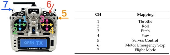
Figure 3.
Channels (CH) mapping on RC.
- In AltHold mode, the throttle stick is raised to 50% and maintained.
- The servos control rotary knob is rotated to a certain position to tilt the propellers to a certain angle.
- The servos control rotary knob is rotated to a larger position to tilt the propellers to a greater angle.
The two different degrees of propeller tilt will generate different magnitudes of horizontal pulling force and yaw moment. In Section 3.2, the theoretical calculation methods for horizontal pulling force and yaw moment are presented based on the rigid body transformation and dynamic model from Section 2. In Section 3.3, the experimental values of horizontal pulling force and yaw moment are presented and compared with the theoretical values.
3.2. Experimental Setup
Figure 4a shows the prototype of the proposed TM-UAV, Tilt-X. The body frame is printed with a 3D printer using ABS-A100 material with a filling density of 100%. Tilt-X has a mass of 2048 g, and the maximum thrust of all four propellers exceeds 7200 g. Figure 4b illustrates the wiring diagram of Tilt-X. All four rotors and all four servo motors are connected to the same power module. Electronic speed controllers (ESCs) are used to control the speed and direction of the rotors, adjusting the current based on commands from the flight controller. BECs are used to convert battery voltage to a stable lower voltage, supplying power to the flight controller and servo motors. Propellers 1 and 2 are CCW propellers, and propellers 3 and 4 are CW propellers. Thus, rotors 1 and 2 are connected to ESCs 1 and 2 differently from the way rotors 3 and 4 are connected to ESCs 3 and 4. Telemetry is used to transmit real-time data, including the positions and status of Tilt-X to the Mission Planner, for monitoring and control purposes.
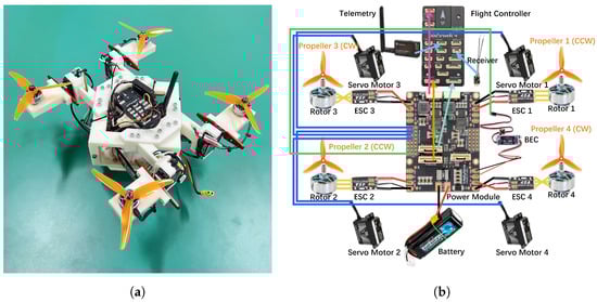
Figure 4.
(a) Prototype of Tilt-X, and (b) its wiring diagram.
In terms of the design of Tilt-X, to ensure that there is no airflow interference between adjacent propellers, the distance between the center of each propeller should be greater than 0.1 []. The maximum propeller radius is calculated as in (14), where max(i) is 4 for Tilt-X as a quadcopter.
The experimental setups are shown in Figure 5. The base of a force/torque (F/T) sensor is fixed to a heavy table to ensure it does not move. A fixed part is attached to the top of the F/T sensor, on which the Tilt-X is placed. This setup allows the F/T sensor to obtain the vertical component of thrust force, , horizontal pulling force, , and yaw moment, , of Tilt-X in the ECF. The experiment of tilting all the propellers in the same direction to apply the horizontal pulling force to the environment is shown in Figure 5a, which is the translation experiment. The experiment of tilting two pairs of propellers symmetrically in opposite directions to maximize yaw moment is shown in Figure 5b, which is the rotation experiment. The horizontal pulling force and yaw moment can be simplified according to Equations (7) and (13) as:
where t, i.e., , is represented this way because, as mentioned in Section 3.1, both the translation experiment and rotation experiment are conducted under AltHold mode. This mode keeps the attitude angles of Tilt-X very small. Therefore, Equations (15) and (16) can be further simplified. Additionally, in AltHold mode, the rotational speeds of each propeller are nearly equal to keep the body’s attitude level, so the moments generated by each propeller cancel each other out. Therefore, Equation (16) is valid only under this condition. In other words, when the attitude angles of Tilt-X are very small and can be ignored, the vertical component of thrust force obtained by the F/T sensor in the ECF is equal to the vertical component of thrust force in the BCF. In this case, Equations (15) and (16) can be simplified to:
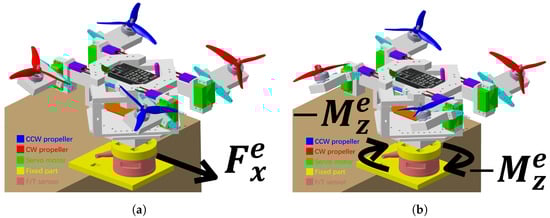
Figure 5.
Configurations of (a) translation experiment for measuring horizontal pulling force, and (b) rotation experiment for yaw moment using an F/T sensor.
To calculate the maximum tilt angle of the propellers, the thrust required for hovering should be considered. An excessive tilt angle will result in insufficient thrust. The range of the propeller tilt angle is thus obtained as:
From Equation (19), the maximum tilt angle of the propellers is calculated to be approximately 73.5 degrees.
The components of Tilt-X are listed in Table 2. The experiments were conducted indoors, as shown in Figure 6. See the supplementary video S1 for the experimental setup and procedure. To measure the horizontal pulling force and yaw moment, a 6-DOF F/T sensor Gamma (SI-130-10, ATI Industrial Automation Co., Apex, NC, USA) was fixed to the table. A jig with a protrusion, i.e., a fixed part, was also fixed on the F/T sensor. Tilt-X was placed on the top of the jig without fixing. The experimental results were compared with Equations (15) and (16). Figure 6a shows the initial calibration step to eliminate the biased F/T signal. In both experiments, the total thrust of all four propellers was always kept less than the mass of Tilt-X to ensure that Tilt-X remained in contact with the F/T sensor to obtain the vertical component of thrust force , horizontal pulling force , and yaw moment of Tilt-X in real-time, as shown in Figure 6b.
Table 2.
The components of Tilt-X.
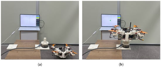
Figure 6.
Experimental environment. (a) Initial calibration of the F/T sensor without the load of Tilt-X. (b) Tilt-X placed on the F/T sensor.
3.3. Experimental Result
To compare the differences between theoretical and experimental values, in both experiments, all four propellers were tilted at specific angles at 20 s and 40 s. For the theoretical values, the horizontal pulling force was calculated using Equation (15) and the yaw moment was calculated using Equation (16). When the attitude angles of Tilt-X were very small, the horizontal pulling force was calculated using Equation (17) and the yaw moment was calculated using Equation (18). For the experimental values, both the horizontal pulling force and the yaw moment were directly measured by the F/T sensor. Figure 7 shows experimental data obtained from the Pixhawk 4. Figure 7a presents the results of the translation experiment, with the propellers tilted as illustrated in Figure 5a. Figure 7b displays the results of the rotation experiment, with the propellers tilted as illustrated in Figure 5b. Both experiments were conducted in AltHold mode.
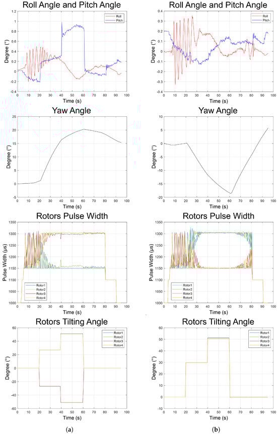
Figure 7.
Experimental data from Pixhawk 4, including roll angle, , pitch angle, , yaw angle, , each rotor’s PW, which indirectly reflects each propeller’s rotational speed, i.e., each propeller’s angular velocity, , and each rotor’s tilting angle, . (a) Experimental results of translation. (b) Experimental results of rotation.
Since the Tilt-X is connected to the telemetry, and the telemetry communicates with the ground station, i.e., Mission Planner, throughout both experiments, the flight log file ‘.tlog’ was converted to a ‘.mat’ file via Mission Planner. In MATLAB, the real-time roll, pitch, and yaw radians measured by the IMU in Pixhawk 4 are obtained from roll_mavlink_attitude_t, pitch_mavlink_attitude_t, and yaw_mavlink_attitude_t, respectively. After converting radians to degrees in units, the results are shown in the ‘Roll Angle and Pitch Angle’ and ‘Yaw Angle’ graphs of Figure 7. The PW of rotors 1 to 4 are obtained from servo1_raw_mavlink_servo_output_raw_t, servo2_raw_mavlink_servo_
output_raw_t, servo3_raw_mavlink_servo_output_raw_t, and servo4_raw_mavlink_servo
_output_raw_t, respectively, and can be directly exported as shown in the ‘Rotors Pulse Width’ graph of Figure 7. The PW of rotor 1 to 4 are obtained from servo9_raw_mavlink_servo_ output_raw_t, servo10_raw_mavlink_servo_output_raw_t, servo11_raw_mavlink_servo_
output_raw_t, and servo12_raw_mavlink_servo_output_raw_t, respectively. Using these PW values, the tilt angles of rotors 1 to 4 can be calculated as shown in the ‘Rotors Tilting Angle’ graph of Figure 7.
As shown in the ‘Roll Angle and Pitch Angle’ graph of Figure 7, the roll, pitch, and yaw angles in both experiments were all small. Consequently, the impact of the attitude angle of the Tilt-X on the horizontal pulling force and yaw moment is limited. To calculate the theoretical values of the horizontal pulling force and yaw moment, Equations (17) and (18), which were simplified from Equations (15) and (16), can be used when the attitude angles can be ignored. Regarding the validity of Equation (16), i.e., whether or not the simplified yaw moment derived from Equations (7) and (13) is feasible, depends on the similarity of the angular velocities of each propeller. Since it is difficult to measure the angular velocity of each propeller directly, its PW signal was used to estimate its angular velocity. Although this indirect method does not provide the exact value, it gives a general understanding of their rotational speeds. CCW rotating propellers generate a CW moment, while CW rotating propellers generate a CCW moment. As shown in the ’Rotors Pulse Width’ graph of Figure 7, the PW values of the CCW rotating propeller 1 and propeller 2 are similar to those of the CW rotating propeller 3 and propeller 4 in both experiments. This symmetry indicates that the angular velocity of each propeller is similar, and the total moment of the propellers is close to zero. Specifically, the c and c generated by the CCW rotating propellers 1 and 2 cancel out the c and c generated by the CW rotating propellers 3 and 4. Therefore, the simplified Equation (16) is valid. In the translation experiment shown in the ‘Rotors Tilting Angle’ graph of Figure 7a, the tilt angles of all four propellers were manually set to be 27 degrees and 51.4 degrees, respectively. However, there were slight deviations in the actual tilt angles of propellers 2 and 4. The actual tilt angles for propeller 2 were measured to be 27 degrees and 50.9 degrees, and those for propeller 4 were 27 degrees and 50.4 degrees. In this work, these small deviations are negligible. In the rotation experiment shown in the ‘Rotors Tilting Angle’ graph of Figure 7b, the tilt angles of all four propellers were set to be 29.8 degrees and 51.4 degrees, respectively. However, there were also slight deviations in the actual tilt angles of propellers 2, 3, and 4 of less than 1.0 degrees.
The experimental data obtained from the F/T sensor and the filtered data are shown in Figure 8. Figure 8a presents the force data measured during the translation experiment, which includes the vertical component of thrust force , as shown in the ‘Vertical Component of Thrust Force’, the horizontal pulling force , as shown in the ‘Horizontal Pulling Force’, their comparison after smoothing with a Gaussian filter, as shown in the ‘Filtered Force’, and the comparison between the measured horizontal pulling force from the translation experiment and the theoretically calculated horizontal pulling force, as shown in the ‘Horizontal Pulling Force Comparison’. Figure 8b shows the force data measured during the rotation experiment, which includes the vertical component of thrust force , as shown in the ‘Vertical Component of Thrust Force’, the yaw moment , as shown in the ‘Yaw Moment’, their comparison after smoothing with the Gaussian filter, as shown in the ‘Filtered Force/Moment’, and the comparison between the measured yaw moment from the rotation experiment and the theoretically calculated yaw moment, as shown in the ‘Yaw Moment Comparison’.
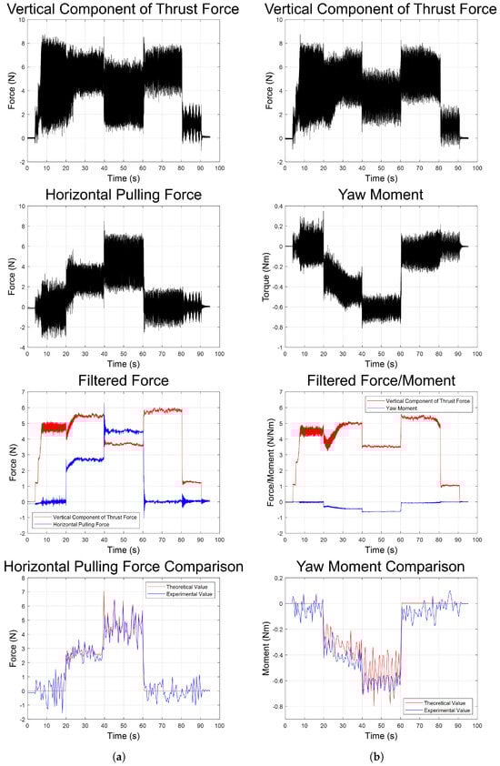
Figure 8.
Experimental data from the F/T sensor, including the vertical component of thrust force , horizontal pulling force , and yaw moment , as well as filtered , , and for observation. Finally, the filtered values, i.e., experimental values, were compared with the theoretical values. (a) Experimental results of translation. (b) Experimental results of rotation.
In both experiments, the tilting angle of the propellers varied while maintaining the throttle stick at 50%. As shown in the ’Vertical Component of Thrust Force’ graph of Figure 8, the vertical component of the thrust of all four propellers in both experiments did not differ significantly. In the translation experiment, when the tilt angle of all four propellers was 27 degrees, the maximum horizontal pulling force was measured to be 5.74 N. When the tilt angle was 51.4 degrees, the maximum horizontal pulling force was measured to be 8.50 N. In the rotation experiment, when the tilt angle was 29.8 degrees, the maximum yaw moment was measured to be approximately 0.65 Nm. When the tilt angle was 51.4 degrees, the maximum yaw moment was measured to be approximately 0.81 Nm. For easier comparison, a Gaussian filter was applied to smooth the high-frequency noise. The Gaussian filter with the standard deviation of 100 was used in this work.
Finally, the theoretical values of pulling force and yaw moment, calculated using Equations (17) and (18), were compared with the experimental values obtained from the F/T sensor. It is worth noting that the calculation of theoretical values involves the attitude angles of Tilt-X and the rotors’ tilting angles. Since the data acquisition frequency of the F/T sensor is much higher than that of the Pixhawk 4, the lowest data acquisition frequency of the rotors tilting angle was used. In the translation experiment, 662,801 Gaussian-filtered vertical components of thrust force and pulling force data were evenly divided into 190 data points based on time. In the rotation experiment, 664,985 Gaussian-filtered vertical components of thrust force and yaw moment data were evenly divided into 191 data points based on time. Due to the significant reduction in the amount of data after downsampling, the standard deviation, , of the filter was set to 5 to retain more of the original sharpness and minor fluctuations, thereby allowing us to see the fine details. From the ‘Filtered Force’, ‘Filtered Force/Moment’, ‘Horizontal Pulling Force Comparison’, and ‘Yaw Moment Comparison’ graphs of Figure 8, it was verified that the filtered horizontal pulling force and yaw moment matched the calculated and the measured values.
4. Conclusions
This paper introduces a novel TM-UAV to maximize the horizontal pulling force and the yaw moment. Compared to extensive research on existing TM-UAVs, the pitch-axis tilting mechanism called Tilt-X is proposed. Compared to other TM-UAVs, it could maximize the horizontal pulling force, since all rotors tilt in the same direction, and the yaw moment, since two rotors tilt in one direction and the other two tilts in the other direction, resulting in producing the moment in the yaw axis. Based on this configuration, it is expected that the proposed Tilt-X can be applied in the following aerial manipulation scenarios:
- Performing aerial horizontal interactions to attach or detach objects on a wall, including surveillance equipment, environmental monitoring instruments, and building inspection devices;
- Performing aerial torsional interactions to turn valves, such as fire hydrant valves and pipeline valves.
In addition, this work presented the rigid body model and the dynamic model of the proposed mechanism. A series of experiments demonstrate the capabilities of this design and verify the accuracy of the mathematical model. However, there are still some discrepancies between the theoretical values and the experimental values, which are unavoidable with manual open-loop control without feedback. Future work will involve designing an automatic feedback closed-loop controller to reduce the error between the experimental and theoretical values of pulling force and yaw moment by real-time control of the propeller tilt angles. This will improve the accuracy of the wrench applied to the environment through force and moment control. Additionally, the Tilt-X experiments presented in this paper for the translation experiment and rotation experiment are not actual flight experiments. Whether or not Tilt-X can perform the aforementioned aerial horizontal interactions and aerial torsional interactions in a real environment remains to be verified. Therefore, research on Tilt-X performing actual APhI tasks will be conducted in the future.
Supplementary Materials
The following supporting information can be downloaded at: https://www.mdpi.com/article/10.3390/app14146181/s1, Video S1: Movie clip about experimental setup and procedure
Author Contributions
Conceptualization, S.Y.K.; methodology, X.T. and S.Y.K.; software, X.T.; validation, X.T.; formal analysis, X.T. and S.Y.K.; writing—original draft preparation, X.T.; writing—review and editing, X.T. and S.Y.K.; visualization, X.T.; supervision, S.Y.K.; project administration, S.Y.K.; funding acquisition, S.Y.K. All authors have read and agreed to the published version of the manuscript.
Funding
This paper was supported by the National Research Foundation of Korea (NRF) grant funded by the Korea government (MSIT) (No. 2022R1A2C2008422) and by the “Regional Innovation Strategy (RIS)” through the National Research Foundation of Korea (NRF) funded by the Ministry of Education (MOE) (2021RIS-002).
Institutional Review Board Statement
This article does not contain any studies with human participants or animals performed by any of the authors.
Informed Consent Statement
This article does not contain patient data.
Data Availability Statement
The data presented in this study are available on request from the corresponding author.
Conflicts of Interest
The authors declare no conflicts of interest.
Abbreviations
The following abbreviations are used in this manuscript:
| TM-UAVs | Tiltrotor multicopter unmanned aerial vehicles |
| M-UAVs | Multicopter unmanned aerial vehicles |
| UAV | Unmanned aerial vehicle |
| SOTA | State-of-the-art |
| VTOL | Vertical takeoff and landing |
| OMAV | Omnidirectional micro-aerial vehicles |
| APhI | Aerial physical interaction |
| DOF | Degrees of freedom |
| COG | Center of gravity |
| BCF | Body coordinate frame |
| ECF | Earth coordinate frame |
| CCW | Counterclockwise |
| CW | Clockwise |
| AltHold | Altitude hold |
| PW | Pulse width |
| RC | Remote controller |
| CH | Channel |
| ESCs | Electronic speed controllers |
| F/T | Force/Torque |
References
- Liu, X.; Dou, M.; Huang, D.; Gao, S.; Yan, R.; Wang, B.; Cui, J.; Ren, Q.; Dou, L.; Gao, Z.; et al. TJ-FlyingFish: Design and Implementation of an Aerial-Aquatic Quadrotor with Tiltable Propulsion Units. In Proceedings of the 2023 IEEE International Conference on Robotics and Automation (ICRA), London, UK, 29 May–2 June 2023; pp. 7324–7330. [Google Scholar]
- Jiang, G.; Voyles, R. A Nonparallel Hexrotor UAV with Faster Response to Disturbances for Precision Position Keeping. In Proceedings of the 2014 IEEE International Symposium on Safety, Security, and Rescue Robotics (2014), Hokkaido, Japan, 27–30 October 2014; pp. 1–5. [Google Scholar]
- Franchi, A.; Carli, R.; Bicego, D.; Ryll, M. Full-Pose Tracking Control for Aerial Robotic Systems with Laterally Bounded Input Force. IEEE Trans. Robot. 2018, 34, 534–541. [Google Scholar] [CrossRef]
- Brescianini, D.; D’Andrea, R. Design, modeling and control of an omni-directional aerial vehicle. In Proceedings of the 2016 IEEE International Conference on Robotics and Automation (ICRA), Stockholm, Sweden, 16–21 May 2016; pp. 3261–3266. [Google Scholar]
- Qin, Y.; Chen, N.; Cai, Y.; Xu, W.; Zhang, F. Gemini II: Design, Modeling, and Control of a Compact Yet Efficient Servoless Bi-copter. IEEE/ASME Trans. Mechatronics 2022, 27, 4304–4315. [Google Scholar] [CrossRef]
- Lee, S.J.; Lee, D.; Kim, J.; Kim, D.; Jang, I.; Kim, H.J. Fully Actuated Autonomous Flight of Thruster-Tilting Multirotor. IEEE/ASME Trans. Mechatronics 2021, 26, 765–776. [Google Scholar] [CrossRef]
- Li, Y.; Qin, Y.; Xu, W.; Zhang, F. Modeling, Identification, and Control of Non-minimum Phase Dynamics of Bi-copter UAVs. In Proceedings of the 2020 IEEE/ASME International Conference on Advanced Intelligent Mechatronics (AIM), Boston, MA, USA, 6–9 July 2020; pp. 1249–1255. [Google Scholar]
- Ryll, M.; Bülthoff, H.H.; Giordano, P.R. A Novel Overactuated Quadrotor Unmanned Aerial Vehicle: Modeling, Control, and Experimental Validation. IEEE Trans. Control. Syst. Technol. 2015, 23, 540–556. [Google Scholar] [CrossRef]
- Ryll, M.; Bicego, D.; Giurato, M.; Lovera, M.; Franchi, A. FAST-Hex—A Morphing Hexarotor: Design, Mechanical Implementation, Control and Experimental Validation. IEEE/ASME Trans. Mechatronics 2022, 27, 1244–1255. [Google Scholar] [CrossRef]
- Allenspach, M.; Bodie, K.; Brunner, M.; Rinsoz, L.; Taylor, Z.; Kamel, M.; Siegwart, R.; Nieto, J. Design and Optimal Control of a Tiltrotor Micro-aerial Vehicle for Efficient Omnidirectional Flight. Int. J. Robot. Res. 2020, 39, 1305–1325. [Google Scholar] [CrossRef]
- Falanga, D.; Kleber, K.; Mintchev, S.; Floreano, D.; Scaramuzza, D. The Foldable Drone: A Morphing Quadrotor that Can Squeeze and Fly. IEEE Robot. Autom. Lett. 2019, 4, 209–216. [Google Scholar] [CrossRef]
- Bucki, N.; Tang, J.; Mueller, M.W. Design and Control of a Midair-Reconfigurable Quadcopter Using Unactuated Hinges. IEEE Trans. Robot. 2023, 39, 539–557. [Google Scholar] [CrossRef]
- Albers, A.; Trautmann, S.; Howard, T.; Nguyen, T.A.; Frietsch, M.; Sauter, C.S.C. Semi-autonomous flying robot for physical interaction with environment. In Proceedings of the 2010 IEEE Conference on Robotics, Automation and Mechatronics, Singapore, 28–30 June 2010; pp. 441–446. [Google Scholar]
- Hamaza, S.; Georgilas, I.; Fernandez, M.; Sanchez, P.; Richardson, T.; Heredia, G.; Ollero, A. Sensor Installation and Retrieval Operations Using an Unmanned Aerial Manipulator. IEEE Robot. Autom. Lett. 2019, 4, 2793–2800. [Google Scholar] [CrossRef]
- Meng, X.; He, Y.; Han, J. Hybrid Force/Motion Control and Implementation of an Aerial Manipulator towards Sustained Contact Operations. In Proceedings of the 2019 IEEE/RSJ International Conference on Intelligent Robots and Systems (IROS), Macau, China, 3–8 November 2019; pp. 3678–3683. [Google Scholar]
- Tzoumanikas, D.; Graule, F.; Yan, Q.; Shah, D.; Popović, M.; Leutenegger, S. Aerial manipulation using hybrid force and position nmpc applied to aerial writing. In Proceedings of the Robotics: Science and Systems 2020, Corvalis, OR, USA, 12–16 July 2020. [Google Scholar]
- Wopereis, H.W.; Ridder, W.L.W.v.d.; Lankhorst, T.J.W.; Klooster, L.; Bukai, E.M.; Wuthier, D.; Nikolakopoulos, G.; Stramigioli, S.; Engelen, J.B.C.; Fumagalli, M. Multimodal Aerial Locomotion: An Approach to Active Tool Handling. IEEE Robot. Autom. Mag. 2018, 25, 57–65. [Google Scholar] [CrossRef]
- Jiang, G.; Voyles, R.; Sebesta, K.; Greiner, H. Mock-up of the exhaust shaft inspection by dexterous hexrotor at the DOE WIPP site. In Proceedings of the 2015 IEEE International Symposium on Safety, Security, and Rescue Robotics (SSRR), West Lafayette, IN, USA, 18–20 October 2015; pp. 1–2. [Google Scholar]
- Bodie, K.; Brunner, M.; Pantic, M.; Walser, S.; Pfändler, P.; Angst, U.; Siegwart, R.; Nieto, J. An Omnidirectional Aerial Manipulation Platform for Contact-Based Inspection. In Proceedings of the Robotics: Science and Systems 2019, Freiburg im Breisgau, Germany, 22–26 June 2019. [Google Scholar]
- Nava, G.; Sablé, Q.; Tognon, M.; Pucci, D.; Franchi, A.; Nava, G.; Sablé, Q.; Tognon, M.; Pucci, D.; Franchi, A. Direct Force Feedback Control and Online Multi-Task Optimization for Aerial Manipulators. IEEE Robot. Autom. Lett. 2020, 5, 331–338. [Google Scholar] [CrossRef]
- Kim, S.; Seo, H.; Kim, H.J. Operating an unknown drawer using an aerial manipulator. In Proceedings of the 2015 IEEE International Conference on Robotics and Automation (ICRA), Seattle, WA, USA, 26–30 May 2015; pp. 5503–5508. [Google Scholar]
- Lee, D.; Seo, H.; Jang, I.; Lee, S.J.; Kim, H.J. Aerial Manipulator Pushing a Movable Structure Using a DOB-Based Robust Controller. IEEE Robot. Autom. Lett. 2021, 6, 723–730. [Google Scholar] [CrossRef]
- Byun, J.; Jang, I.; Lee, D.; Kim, H.J. A Hybrid Controller Enhancing Transient Performance for an Aerial Manipulator Extracting a Wedged Object. IEEE Trans. Autom. Sci. Eng. 2023, 1–10. [Google Scholar] [CrossRef]
- Benzi, F.; Brunner, M.; Tognon, M.; Secchi, C.; Siegwart, R. Adaptive Tank-based Control for Aerial Physical Interaction with Uncertain Dynamic Environments Using Energy-Task Estimation. IEEE Robot. Autom. Lett. 2022, 7, 9129–9136. [Google Scholar] [CrossRef]
- Orsag, M.; Korpela, C.; Bogdan, S.; Oh, P. Dexterous Aerial Robots—Mobile Manipulation Using Unmanned Aerial Systems. IEEE Trans. Robot. 2017, 33, 1453–1466. [Google Scholar] [CrossRef]
- Martinez, R.R.; Paul, H.; Shimonomura, K. Aerial Torsional Work Utilizing a Multirotor UAV with Add-on Thrust Vectoring Device. Drones 2023, 7, 551. [Google Scholar] [CrossRef]
- Valavanis, K.P. Advances in Unmanned Aerial Vehicles: State of the Art and the Road to Autonomy, 2007th ed.; Springer: Berlin/Heidelberg, Germany, 2007; p. 176. [Google Scholar]
- Quan, Q. Introduction to Multicopter Design and Control, 1st ed.; Springer Nature: Singapore, 2017; p. 62. [Google Scholar]
Disclaimer/Publisher’s Note: The statements, opinions and data contained in all publications are solely those of the individual author(s) and contributor(s) and not of MDPI and/or the editor(s). MDPI and/or the editor(s) disclaim responsibility for any injury to people or property resulting from any ideas, methods, instructions or products referred to in the content. |
© 2024 by the authors. Licensee MDPI, Basel, Switzerland. This article is an open access article distributed under the terms and conditions of the Creative Commons Attribution (CC BY) license (https://creativecommons.org/licenses/by/4.0/).