1. Introduction
As comprehensive products of the global rapid arrival concept and high-speed flight technology, hypersonic vehicles have the characteristics of high speed, strong maneuverability, long flight ranges, and strong penetration ability [
1]. As a typical hypersonic vehicle configuration, hypersonic waveriders exhibit fast time variance, strong nonlinearity, and uncertainty during flight, which pose challenges to flight control [
2]. In modern scenarios, flight environments and missions are imposed with more complexity and diversity, which creates more stringent requirements for the flight performance of the aircraft [
3,
4]. Due to the fixed configuration of these vehicles, the flight range and maneuverability of traditional hypersonic waveriders are often limited. By combining morphing technology with hypersonic vehicles, a hypersonic morphing waverider (HMW) can be designed. Since the advantages of both morphing technology and hypersonic vehicles are integrated in HMWs, an HMW can change its geometric configuration adaptively according to different flight environments and missions, which enables it to achieve the best performance at hypersonic speed throughout the entire flight [
5,
6]. For instance, to achieve a larger downrange, the configuration with the best lift-to-drag ratio can be obtained for HMWs. Similarly, a low drag configuration can be obtained to reduce the velocity loss, thus maintaining the attack kinetic energy. In the past few decades, with the advancement of novel materials, structural mechanisms, and actuation devices, as well as the large-scale integration and application of them in aircraft design, morphing aircraft have ushered in a new development climax [
7,
8].
The U.S. Naval Research Laboratory (NRL) has conducted extensive research on morphing waveriders in recent years. In reference [
9], a morphing bottom surface was used to design a morphing waverider, and the aerodynamic performance was analyzed in terms of the constant dynamic pressure and constant altitude under different Mach numbers. The feasibility of the NRL morphing waverider concept was further investigated, and it demonstrated that by deforming the lower stream surface, a morphing waverider could obtain optimal aerodynamic performance across Mach numbers ranging from Mach 5 to Mach 10 [
10]. In [
11], control requirements and performance were investigated in a morphing waverider under a range of Mach numbers from Mach 3.5 to Mach 5. In addition, some other morphing waveriders have been designed. In [
12], a waverider with a variable swept wing was designed to achieve the best flight performance. In [
13], a multistage waverider was designed based on conical flow theory, and the aerodynamic performance was analyzed.
The studies above mainly focus on configuration and aerodynamic characteristics, which is one basic part of HMWs [
14]. Considering the strong coupling caused by deformation, HMWs have higher nonlinearity, stronger time variance, and larger uncertainty than conventional hypersonic waveriders, and it is difficult to satisfy the high stability, robustness, and control accuracy requirements with traditional control methods. Therefore, the establishment of a motion model of an HMW and the design of a controller with strong robustness are great challenges.
Up to now, various control algorithms have been applied to morphing aircraft controller designs. Reference [
15] introduced the modeling of a large-scale planform altering flight vehicles systematically and discussed the principles of flight control. Sliding-mode control is widely used in nonlinear control because of its robustness [
16]. In reference [
17], a sliding-mode controller was proposed for a tailless morphing wing aircraft to track the maneuver reference command to avoid difficulty in precise aerodynamic modeling. To address the control and control allocation problem of a morphing aircraft, the NDOISMC method, which combined a nonlinear disturbance observer and incremental sliding-mode control, was proposed for morphing aircraft, and an SOCP-based control allocation was used to allocate the control of different actuators [
18]. In reference [
19], a super-twisting sliding-mode controller was designed for HMW trajectory tracking. In [
20], an explicit model of a variable-swept-wing aircraft was proposed, considering the variations in aerodynamics, mass, and inertia, and an adaptive super-twisting sliding-mode controller was designed to track the reference trajectory. A morphing aircraft dynamic model based on the KANE method was also established, and an adaptive integral sliding-mode controller was proposed, which could stabilize the LPV system in finite time [
21]. In addition, several advanced algorithms have been developed for morphing aircraft control. To address the control of morphing aircraft in a full envelope, a switching polytopic linear parameter-varying (SPLPV)-based gain-scheduled controller was proposed in [
22]. In reference [
23], a six-DOF model of a variable-swept-wing waverider was established, and a nonlinear model predictive controller considering system disturbance was proposed. Lateral weaving simulation showed that the morphing waverider had better ability in different flight conditions. To realize autonomous morphing and aerodynamic performance optimization for a new bionic morphing UAV, a deep deterministic policy gradient (DDPG) algorithm was developed for deformation control [
24]. Aside from attitude and trajectory tracking control, some scholars have carried out research on the integrated guidance and control (IGC) of hypersonic morphing vehicles (HMVs). In reference [
25], an IGC model with a terminal angular constraint of a hypersonic variable-span missile was established, and an adaptive dynamic surface control backstepping method was proposed. A simulation showed that span variety is useful for the fast and stable control of hypersonic morphing missiles. Similarly, an adaptive dynamic surface method was proposed with the IGC system for an HMV; the simulation results indicated that the HMV had lower velocity loss and larger terminal velocity than an invariable-span vehicle [
1].
For HMWs, the system states are expected to converge in a short time. In the abovementioned control approaches of morphing aircraft, the closed-loop system is usually finite-time stable, which means the system states will reach equilibrium in a finite time. However, for such a finite-time system, the settling time depends on the initial state. Since the states of the HMW in near space are under great uncertainty, there is an urgent need to develop a controller with a small bounded convergence time independent of initial states.
Based on the finite-time convergence theory, Polyakov [
26] first proposed the fixed-time convergence concept and the stability analysis methods. Compared with the finite-time convergence system, the convergence time of the fixed-time system is independent of the initial system states. In reference [
27], an adaptive fixed-time guidance law with attack angle constraint was proposed for intercepting maneuvering targets. In [
28], a fixed-time cooperative guidance law with a desired terminal attack angle was proposed. A non-singular terminal sliding mode (NFTSM) controller was proposed for missile agile turning, and a fixed-time extended state observer (ESO) was applied to eliminate the chattering by online estimation of the disturbance [
29]. In [
30], a novel ESO-based NFTSM controller was proposed for a vertical take-off and vertical landing (VTVL) reusable launch vehicle. For a rigid spacecraft, a novel fixed-time attitude controller based on a backstepping technique and power integrator was proposed [
31]. In [
32], an event-triggered fixed-time attitude controller based on a multivariable sliding mode manifold was designed for an HMV. Currently, research on morphing aircraft has mainly focused on aerodynamic design and attitude–trajectory control. The typical control method is the sliding mode control (SMC), and other control techniques are not common; moreover, the current mainstream SMC methods for morphing aircraft are often based on the finite-time stability theory, and such controllers are unable to guarantee that the system states will converge in a bounded time since HMW dynamics have serious uncertainty and complex disturbance. Therefore, there are still challenges in fixed-time control algorithm design for HMWs.
Motivated by the aforementioned outstanding studies and discussions. In this article, a dynamic model of an HMW with a variable-span wing based on multi-body dynamics is established while taking additional forces and moments into account. Next, the HMW longitudinal dynamic model is transformed into a strict feedback form, and a fixed-time backstepping controller is proposed for the HMW attitude tracking. To overcome the influence of disturbances, a fixed-time disturbance observer is used to perform the disturbance online estimation. Moreover, a nonlinear filter is proposed to address the “explosion of terms” problem while guaranteeing the system’s fixed-time convergence property. The proposed fixed-time backstepping controller has good robustness in response to time variance and uncertainty of the HMW with the advantage of overcoming the total disturbance. Above all are the main contributions of this paper.
The remainder of this paper is organized as follows: In
Section 2, a dynamic model of the HMW is established considering additional forces and moments.
Section 3 presents a novel fixed-time backstepping controller for the HMW. In
Section 4, the numerical demonstrations are conducted to validate the effectiveness of the controller.
Section 5 concludes this paper.
3. Controller Design
3.1. Preliminaries
Since the HMW has strong nonlinearity and uncertainty and is easily affected by external disturbances, a small bounded convergence time is necessary for the controller. Nevertheless, traditional methods based on finite-time stability are unable to guarantee the system states to converge within a bounded settling time, which has led to limitations in the application of such methods. Afterward, the introduction of the fixed-time stability concept provides new techniques. Before starting controller design, it is necessary to introduce relevant concepts and lemmas.
Consider the following system:
where
is the system state vector, and
is a nonlinear function. The solutions of Equation (21) are defined in the sense of Filippov, and it is assumed that the system has a zero equilibrium point.
Definition 1 ([
26])
. The equilibrium point of the system (21) is said to be a fixed-time stable equilibrium point if it is finite-time stable with a bounded settling-time function whose upper bound is a positive number ; thus, . Definition 2 ([
26])
. The set M is said to be a fixed-time attractive for the system (21) if it is globally finite-time attractive with a bounded settling-time function whose upper bound is a positive number ; thus, . Lemma 1 ([
26,
31])
. Suppose that there exists a Lyapunov function satisfying where , , , and are some positive constants satisfying , ; then, the equilibrium point is fixed-time stable, and the settling time satisfying . In Lemma 1, set , and the following corollary can be obtained.
Corollary 1. Suppose that there exists a Lyapunov function satisfying
where , , , are some positive constants satisfying , ; then, the equilibrium point is fixed-time stable, and the settling time . Lemma 2 ([
33])
. Suppose that there exists a Lyapunov function satisfyingwhere , , , and are some positive constants satisfying , , and is a small positive number; then, the system is fixed-time stable and the system states will converge to an arbitrarily small neighborhood of the origin, i.e., with in fixed time bounded by Lemma 3 ([
34])
. Consider the following system:where , are system states; , are positive constants satisfying and ; is the amplification factor; denotes the uncertain disturbance, satisfying and .
The nonlinear function is defined as follows:where , .
Then, the system (26) will converge to a neighborhood of the origin in fixed time.
3.2. Fixed-Time Backstepping Controller Design
Generally, to achieve the desired flight profile of the HMW, the purpose of controller design is to track the AOA command precisely. And the backstepping control is a feasible method with the step-by-step recursive design process for this nonlinear system [
35,
36]. Therefore, in order to apply the backstepping technique, the longitudinal short-period dynamic equations with a strict feedback form are considered as
where
;
;
; and
and
are disturbances in the AOA channel and pitch rate channel, respectively.
Assumption 1 ([
37,
38])
. The unknown disturbance and its first-time derivatives are bounded, satisfying and , where and are the upper bound. According to the backstepping control methodology, there are two steps for the attitude controller design.
Step 1: Define the AOA tracking error as
where
is the reference AOA command.
Taking the time derivative and substituting (28), the AOA tracking error dynamic equations can be obtained as
The virtual control input
is designed as
where
,
, and
are positive constants,
,
.
To avoid the problem of the “explosion of terms” caused by directly differentiating the virtual control
, the idea of dynamic surface control [
39] (DSC) is used. Different from the traditional DSC which uses a first-order filter, in this article, a nonlinear first-order filter is designed, to guarantee the fixed-time stability of the overall system. The nonlinear first-order filter is given as
where
is the time constant of the filter and
is the output of
after being filtered.
Define the filtering error
and pitch rate tracking error
as follows:
Then, the AOA tracking error dynamic equation becomes
Step 2: The pitch rate tracking error dynamic equation can be expressed as
Substituting (28) into (35) gives
To achieve fixed-time convergence, the control input
is designed as
where
,
, and
are positive constants.
3.3. Fixed-Time Disturbance Observer Design
The HMW has strong nonlinearity and fast time variance, and there are strong aerodynamic uncertainties under hypersonic flight; at the same time, there are problems such as system non-modeling dynamics and internal and external perturbations during the flight of the HMW. Therefore, is a total disturbance considering various uncertainties. It should be noted that the disturbances are different in different environments, and the disturbances are also different at different moments in the same environment; thus, the disturbances have strong randomness.
To ensure the robustness of the controller, in the control law shown in Equations (31) and (37), in order to eliminate the influence of disturbance , the switching gain is utilized. Under this circumstance, the design of this control law depends highly on the estimation of the upper bound of the disturbance since the upper bound of the disturbance is hard to obtain. In addition, due to the strong randomness of disturbance, its upper bound is possibly large, thus leading to a large switching gain , causing serious chattering in the control system, which is not applicable in practical engineering.
In order to improve the robustness of the system and avoid chattering, the extended state observer [
40] technique is used to estimate disturbances online and to compensate for the control laws accordingly. In this paper, the fixed-time extended disturbance observer for the AOA channel is designed as follows:
Similarly, the fixed-time disturbance observer for the pitch rate channel can be designed as
where
,
,
, and
are the estimations of
,
,
, and
, respectively;
,
,
,
are positive constants, satisfying
,
and
,
;
are amplification factors.
The nonlinear functions
and
are defined as
And the nonlinear functions
and
are defined as
where
,
.
Theorem 1. Consider the system of the first equation of Equation (28), and design the fixed-time disturbance observer as Equations (38) and (39) with the appropriate parameters; then, the disturbance estimation errors and will converge to a neighborhood of the origin in fixed time.
Proof of Theorem 1. Firstly, define the observer estimation errors as
Taking the time derivative of Equation (42) and substituting Equation (28) result in the following error dynamics:
It follows from Assumption 1 and Lemma 3 that the estimation errors and will converge to the neighborhood of the origin in fixed time.
Similarly, we can define the disturbance observer errors
and
, and then fixed-time convergence of disturbance observer for the pitch rate channel can be proven with the same steps above. Suppose that the convergence times of
and
are bounded by
and
, respectively, and the detailed derivation process can be found in reference [
34]; thus, this paper will not elaborate on it further. The proof is completed. □
Using the disturbance estimations
and
to compensate for control laws (31) and (37), the new control laws become
where
and
are the disturbance observer estimation bounds, satisfying
and
.
3.4. Stability Analysis
Theorem 2. Consider system (28) with the control laws (44), (45), and the nonlinear first-order filter (32) under Assumption 1. Then, the closed-loop system is fixed-time stable, and the tracking errors can be stabilized in an arbitrarily small neighborhood of the origin.
Before proving Theorem 2, the following necessary lemma that contributes to the derivation process needs to be stated:
Lemma 4 ([
33])
. If and , then Proof of Theorem 2. Define a Lyapunov function candidate as follows:
Taking the time derivative of
gives
Since the disturbance estimation error dynamics are unrelated to control inputs, the estimation errors and will converge to the neighborhood of the origin in fixed time and , respectively, according to Theorem 1.
When
, we have
,
,
. Then, substituting Equations (32), (34), (36), (44) and (45) into Equation (48), we have
where
is the upper bound of
.
Using Young’s inequality for
and
in the above equation, we can obtain
Consider the following inequality:
where
,
, and
. Then, we can obtain
where
.
Therefore, we have the following inequality:
Substituting Equations (53) and (54) into Equation (50), we obtain
where
,
,
.
Assumption 2. The control parameters are selected appropriately so that
,
,
are positive. Since
and
hold, according to Lemma 4, for the first two terms in Equation (55), we have
For the terms with the same power in Equation (58), using Lemma 4, we have
Then, we can obtain
where
,
,
.
Following Assumption 2 and Lemma 2, we can conclude that the system is fixed-time stable and the system states will converge to an arbitrarily small neighborhood of the origin. The attractive region is
with
, and the convergence time
is bounded by
In summary, the closed-loop system is fixed-time stable with the convergence time bounded by . The proof is completed. □
4. Numerical Demonstrations
This section presents numerical demonstrations that were conducted on MATLAB R2022a software (version: 9.12.0.1884302) to demonstrate the effectiveness of the proposed fixed-time backstepping controller. The initial conditions of the HMW are given as follows:
m/s,
deg,
rad/s. Five scenarios are considered in this article. The designed parameters of the controller and observers are shown in
Table 1 and
Table 2, the simulation step size is set as 0.0001 s.
The AOA command is set as
deg; the wing morphing law is given as
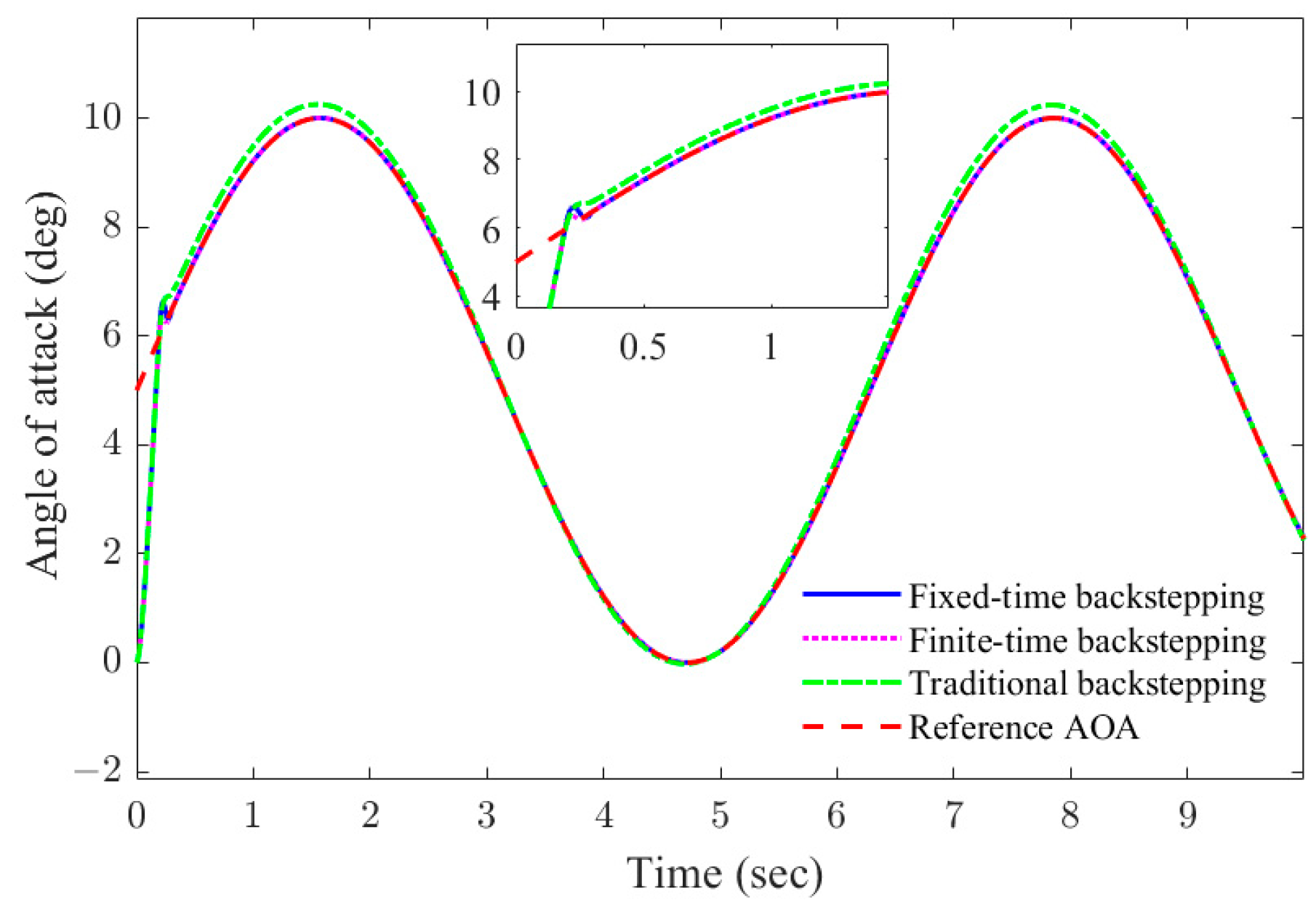
Scenario 1. In this scenario, in the case of symmetrical morphing of left and right wings, comparisons between the proposed observer-based fixed-time backstepping controller of Case1, finite-time backstepping controller (by making ) of Case2, and traditional backstepping controller (by making ) of Case3 are conducted without disturbance and uncertainty, and .
Figure 3 and
Figure 4 show that both the fixed-time and finite-time backstepping controllers can track the reference angle of attack command accurately with comparable response speeds, while the basic backstepping controller has a small tracking error. For three controllers, the elevator deflections experience brief chattering at the beginning and then quickly become smooth as shown in
Figure 5.
Scenario 2. During the flight process of the HMW, there are strong disturbances. Meanwhile, due to the complex flight environment and limited accuracy of aerodynamic estimation methods, there are often estimation errors in aerodynamic data, resulting in strong aerodynamic uncertainty. Both the disturbance and uncertainty have a significant impact on HMW flight performance. Therefore, in this scenario, strong disturbance and aerodynamic uncertainty are introduced to the HMW dynamics, and comparisons between the three controllers are conducted. And
is given as 8 s. The aerodynamic uncertainty is set as
, and the strong disturbances of AOA channel and pitch rate channel are given as
Figure 6 and
Figure 7 reveal that the proposed observer-based fixed-time backstepping controller can track AOA command precisely; it responds faster than other methods, and the tracking error can converge to a range of zero quickly. It also can be seen that the finite-time and basic backstepping controllers are unable to guarantee tracking accuracy, especially for the latter one which has a large tracking error.
Figure 8 shows the elevator deflection of each controller; it is obvious that the elevator deflection of the fixed-time controller is smooth apart from the initial short chattering, while the finite-time controller still has severe chattering in the later stages of control.
Figure 9 and
Figure 10 demonstrate the estimations of disturbances of
and
. Obviously, the fixed-time disturbance observer of each channel has a good estimation for disturbance, and it is the key to the proposed method being able to accurately track the AOA command.
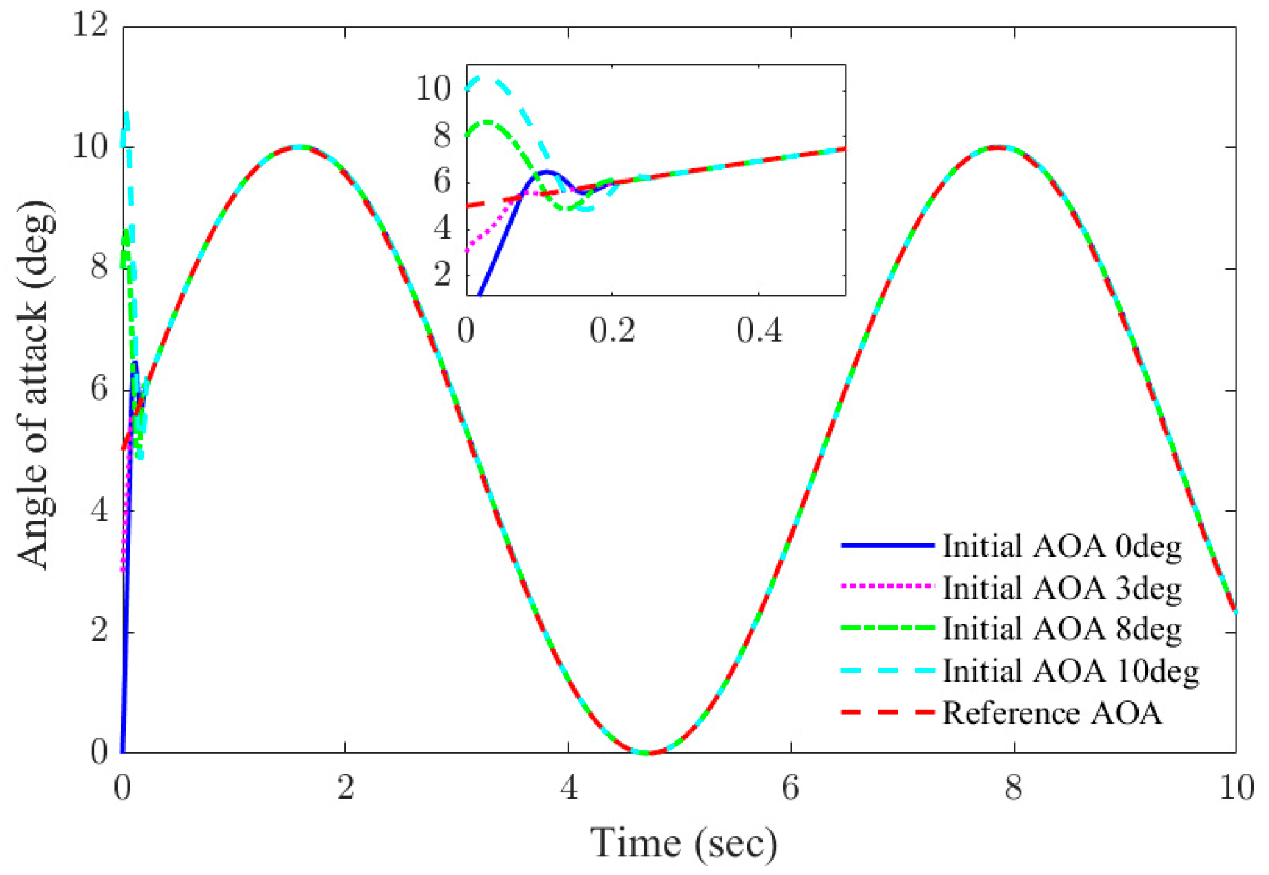
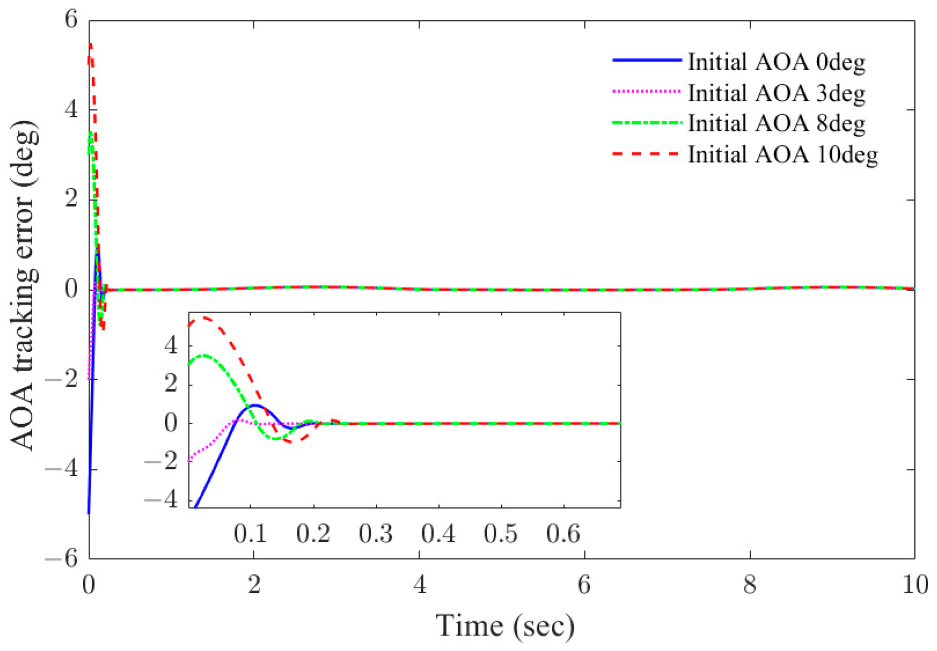
Scenario 3. To demonstrate the advantage of fixed-time convergence of the proposed controller independent of initial conditions, four cases with different initial conditions are considered as shown in
Table 3.
is set as 8 s, the aerodynamic uncertainty is set as
, and the strong disturbances of the AOA channel and pitch rate channel are given as Equations (64) and (65).
As shown in
Figure 11 and
Figure 12, the AOA tracking errors will converge to a neighborhood of origin in a short time under different initial conditions in the presence of disturbances and uncertainty, and this verifies the fixed-time convergence of the proposed controller.
Figure 13 shows the elevator deflection under different cases; the elevator deflections are smooth and change slowly due to the AOA command apart from the initial short chattering. As shown in
Figure 14 and
Figure 15, the disturbance estimation errors of the proposed disturbance observer can converge to the neighborhood of the origin instantaneously.
Scenario 4. For the HMW, the symmetrical wing morphing has a significant impact on the flight state of the aircraft. Therefore, it is necessary to verify the controller’s ability to guarantee flight stability at different morphing speeds. Therefore, four cases with different morphing speeds are chosen as shown in
Table 4. The aerodynamic uncertainty is set as
, and the strong disturbances are the same as those in Scenario 3.
The additional forces and moments caused by wing morphing are shown in
Figure 16; it is obvious that the morphing will result in significant additional forces and moments, which will change with the aircraft’s attitude.
As shown in
Figure 17 and
Figure 18, the AOA can track the command accurately, and the AOA tracking errors will converge to a neighborhood of origin under different morphing speeds in the presence of disturbances and uncertainties; this indicates that the proposed controller has good adaptability in response to different morphing speeds. The elevator deflection is smooth and changes slowly, as shown in
Figure 19. As shown in
Figure 20 and
Figure 21, the disturbance estimation errors of the proposed disturbance observer can converge to the neighborhood of the origin in a short time. In summary, for the proposed controller, symmetrical morphing speed has little influence on the attitude control of the HMW.
Scenario 5. In the HMW flight process accompanied by high dynamics, the actuators often face harsh environments, which in turn lead to the dangerous situation of different wing extension lengths on both sides, jeopardizing the HMW flight stability. This scenario focuses on the dangerous situation of asymmetric morphing of wings. In this scenario, in order to check the adaptive capability of the proposed controller in response to dangerous situations of asymmetric wing morphing, the reference angle of attack command is tracked based on the proposed controller in the presence of strong external disturbances and uncertainties. Therefore, four cases with different asymmetry morphing are chosen, as shown in
Table 5. The aerodynamic uncertainty is set as
, and the strong disturbances of the AOA channel and pitch rate channel are given as Equations (64) and (65). The asymmetry morphing rate is defined as
where
and
denote the wing span of the left wing and the right wing, respectively.
The additional forces and moments caused by wing asymmetry morphing are shown in
Figure 22; it can be seen that the additional moments and the additional force along the body axial direction of the HMW change significantly as the asymmetric deformation rate is changed.
As shown in
Figure 23 and
Figure 24, the AOA can track the command accurately, and the AOA tracking errors will converge to a neighborhood of origin simultaneously under different asymmetry morphing rates in the presence of strong disturbances and uncertainties; this reveals that the proposed controller has good adaptability in response to asymmetric morphing situations. The elevator deflections are smooth and change slowly, as shown in
Figure 25. As shown in
Figure 26 and
Figure 27, the disturbance estimation errors of the proposed disturbance observer can converge to the neighborhood of the origin instantaneously. In summary, for a well-designed controller, asymmetrical morphing has little influence on the attitude control of the HMW.
From the five scenarios, we can draw the following conclusions: (1) the proposed fixed-time backstepping controller has a faster convergence, less chattering, and higher accuracy than a finite-time or basic backstepping controller; (2) the fixed-time disturbance observer can estimate disturbances precisely, which improves the controller’s robustness; (3) the overall closed-loop system can achieve fixed-time convergence which does not depend on the initial states; (4) for a well-designed controller, the asymmetry and symmetry morphing rates of the HMW have little influence on the HMW longitudinal fight performance.


