Article

The Electromagnetic Exposure Level of a Pure Electric Vehicle Inverter Based on a Real Human Body

Key Laboratory of Opto-Electronic Technology and Intelligent Control of the Ministry of Education, Lanzhou Jiaotong University, Lanzhou 730070, China
*
Author to whom correspondence should be addressed.
Appl. Sci. 2024, 14(1), 32; https://doi.org/10.3390/app14010032
Submission received: 15 November 2023 / Revised: 13 December 2023 / Accepted: 14 December 2023 / Published: 20 December 2023

Abstract

:
In order to quantitatively analyze the electromagnetic exposure dose of an inverter in a pure electric vehicle to the driver’s body and assess the safety of the electromagnetic exposure, based on a real human anatomy model in the virtual home project, a real human model with several organs and tissues, including muscles, bones, a heart, lungs, a liver, kidneys, a bladder, a skull, a scalp, white matter, and a cerebellum, was constructed. The inverter of a pure electric vehicle is considered to be the electromagnetic exposure source; for this study, an equivalent electromagnetic environment model composed of a real human body, an inverter, and a vehicle body was built. The distribution of induced fields in the driver’s tissues and organs was calculated and analyzed using the finite element method. The results show that the distribution of the magnetic flux density, induced electric field, and induced current density in the driver’s body was affected by the spatial distance of the inverter. The farther the distance was, the weaker the value was. Specifically, due to the different dielectric properties of the different tissues, the induced field in the different tissues was significantly different. However, the maximum magnetic flux density over the space occupied by the driver’s body and induced electric field in the driver’s trunk and central nervous system satisfied the exposure limits of the International Commission on Non-Ionization Radiation Protection, indicating that the electromagnetic environments generated by the inverter proposed in this paper are safe for the vehicle driver’s health. The numerical results of this study could also effectively supplement the study of the electromagnetic environments of pure electric vehicles and provide some references for protecting the drivers of pure electric vehicles from electromagnetic radiation.

1. Introduction

Vehicles are the world’s second largest source of carbon emissions [1]. Pure electric vehicles (PEVs) have entered a stage of explosive development [2] with the new round of technological and industrial revolution, as well as the proposal of ‘zero emissions’ and ‘carbon neutrality’ goals in many countries. They will help to cope with the challenges of climate change and improve the global ecological environment [3].
The PEV power system mainly consists of high-power electrical components, such as inverters [4], converters, high-voltage power harnesses, and power battery packs [5,6]. The compact space inside the PEVs brings the passengers closer to these high-power devices. So, both the driver and passengers are exposed to the electromagnetic environment generated by the high-power devices when driving. According to statistical data, the average time spent driving for a member of the general public on weekdays is about 1–2 h [7]. In the context of pure electric vehicles, when the human body is exposed to the low-frequency electromagnetic field, the human body is affected due to Faraday’s law of electromagnetic induction, and induced fields will form inside the human body. Once these induced fields exceed a certain threshold inside the human body, they may have an impact on human health [8].
For the assessment of human electromagnetic exposure, the Institute of Electrical and Electronics Engineers (IEEE) and the International Commission on Non-Ionizing Radiation Protection (ICNIRP) have defined the human limits for electromagnetic exposure [9,10,11]. Different countries or regions generally refer to the exposure limit guidelines/standards defined by the two major international organizations when it comes to issues related to electromagnetic exposure limits. The exposure limits defined by the ICNIRP are adopted in this paper. The ICNIRP has established occupational and general public exposure limits for electromagnetism in different frequency bands to assess the safety of human electromagnetic exposure and has defined basic restrictions (BRs) for the electric fields induced within the tissues and reference levels (RLs) for the environmental fields [10].
Relevant epidemiological studies have found that many diseases may be related to long-term exposure to electromagnetic fields [12,13]. However, other studies have also found that exposure to electromagnetic fields can have positive effects (e.g., on memory recovery in organisms and in treating stroke patients) [14,15,16]. Actually, a consensus has not been reached regarding the effects of electromagnetic exposure on human health. For the electromagnetic environment of electric vehicles, Li et al. [17] measured the magnetic flux density near the rear seats of different electric vehicles. These measurements were used to calculate the induced electric fields of adult and infant passengers. Sztafrowski and Winiarz [18] studied the distribution of magnetic flux density in different seating positions of electric and hybrid electric vehicles under different operating conditions. Bae and Park [19] studied the electromagnetic environment generated by the wired charging systems of electric vehicles with different charging speeds and showed that the magnetic flux density generated by standard chargers was higher than that of fast chargers. Tell and Kavet [20] and Wyszkowska et al. [21] measured the different distribution characteristics of electromagnetic fields in the carriages of electric, hybrid, and fuel vehicles, and the measurement results all satisfied the RLs defined by the ICNIRP. Atanasov et al. [22] studied the distribution of electric fields inside a vehicle for different wireless communication scenarios and explored the possibility of collecting energy from electromagnetic fields inside the vehicle. Jeladze et al. [23] studied the electromagnetic exposure level of wireless communication equipment to the human body in a vehicle. The results of this study showed that the specific absorption rate of the human tissue showed an increasing trend due to the resonance phenomenon and high response field in the vehicle. Some researchers have investigated the exposure level of the electromagnetic environment generated by vehicles’ wireless charging systems to the human body, and the results of these studies show that the exposure level is within the ICNIRP limits [24,25,26,27]. Mou and Lu [28] studied the influence of vehicle bodies with different materials on the electromagnetic exposure dose of passengers in a PEV and found that the aluminum alloy body could reduce the magnetic flux density over the space occupied by the driver’s body inside the vehicle by 99.76%.
In response to the complexity of the electromagnetic environment inside electric vehicles and to prevent potential health risks, many researchers have studied the use of protective materials [29,30,31] to minimize the impact of this electromagnetic environment on the human bodies of passengers.
Thus far, in the context of studying human electromagnetic dosimetry, some studies have used approximate simple human models [32,33], but more studies have used an anatomical real human model based on high-resolution MRI scanning [34,35,36]. In order to better understand the effects of electromagnetic exposure in pure electric vehicles on real human tissues and organs, this study incorporated a real human anatomy model with detailed organ and tissue characteristics [37,38]. Comsol Multiphysics 6.0 software, based on the finite element method (FEM), was used; the inverter in the PEV was considered to be the electromagnetic exposure source. The magnetic flux density (B-field) over the space occupied by the driver’s body, as well as the electric field (E-field) and the induced current density (J) in different tissues and organs of the driver’s body, were calculated by the FEM. In this paper the B-field and the E-field are compared with the exposure limits stipulated by the ICNIRP to assess the exposure level to the driver’s body in the electromagnetic environment of the inverter. This study could help to further clarify the human exposure limit for the electromagnetic environment generated by PEV inverters, as well as the effects that the electromagnetic environment of PEVs have on different tissues and organs of the human body, and effectively supplement studies on electromagnetic exposure in the context of PEVs.

2. Materials and Methods

Using the epidemiological survey method to assess the safety of human electromagnetic exposure, considering individual differences and sample size, is not ideal, as it has a long cycle and the results produced can be uncertain. However, the experimental measurement method cannot obtain the field distribution in different tissues of a living human body. The bioelectromagnetic dosimetry method, based on numerical calculations, precisely avoids the shortcomings of the two methods in the context of studying human electromagnetic exposure [39]. Thus, through using electromagnetic dosimetry, the limits of different tissues in the human body to electromagnetic exposure from the electromagnetic environment generated by a PEV inverter was studied.

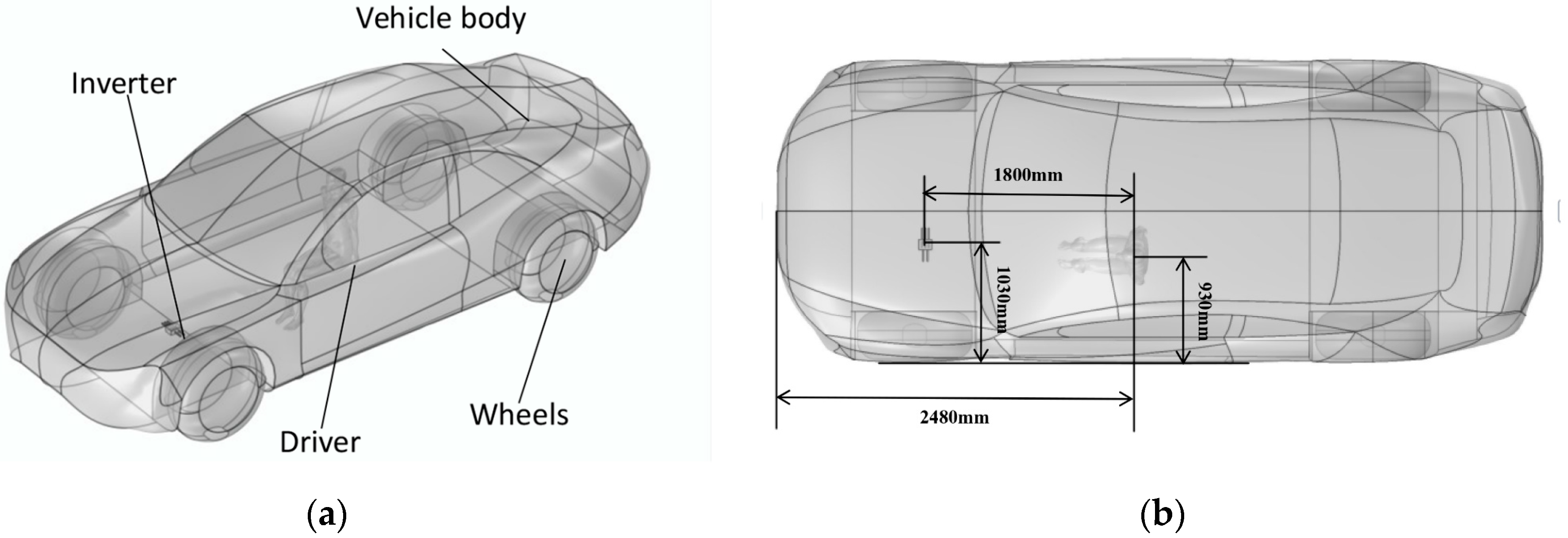
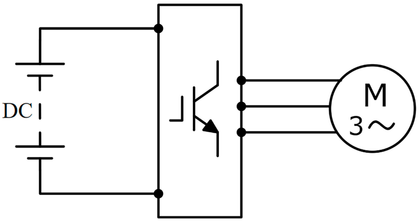
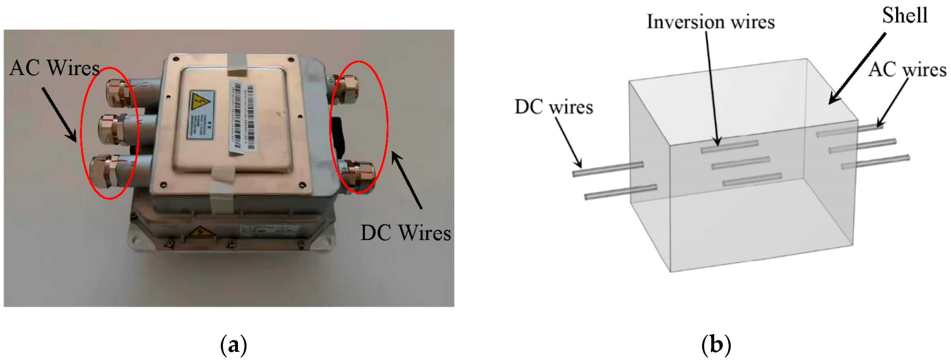
2.1. The PEV Inverter Model

For this study, a pure electric vehicle body model was established according to the actual size of the PEV. In the model, the size of the vehicle body was about 5207 mm × 2034 mm × 1655 mm, as shown in Figure 1a [40], and the material of the vehicle body was an aluminum alloy. The model also included the driver’s body and the inverter model.
The position of the driver and the inverter in the vehicle is shown in Figure 1b. The distance from the driver’s body to the front of the vehicle was about 2480 mm; the distance to the inverter center was about 1800 mm. The vertical distance from the left door to the driver’s body was about 930 mm, and the distance to the inverter center was about 1030 mm.
The PEV inverter is an important electronic device, as it can convert a DC into an AC and provide the AC power to the driver motors. As a device that connects battery packs and driver motors, PEV inverters are high-powered and have multi-frequency currents. Figure 2 shows a schematic diagram of the inverter connection [41].
The exposed source was a vehicle inverter with a power of 12 kW (Semikron, Nuremberg, Germany), a size of 320 mm × 249 mm × 234 mm, and a maximum input DC voltage of 650 V; the output voltage was 400 Vrms, and the maximum output current was 60 Arms (f = 100 Hz). The operating frequency of the inverter was 5400 Hz [42].

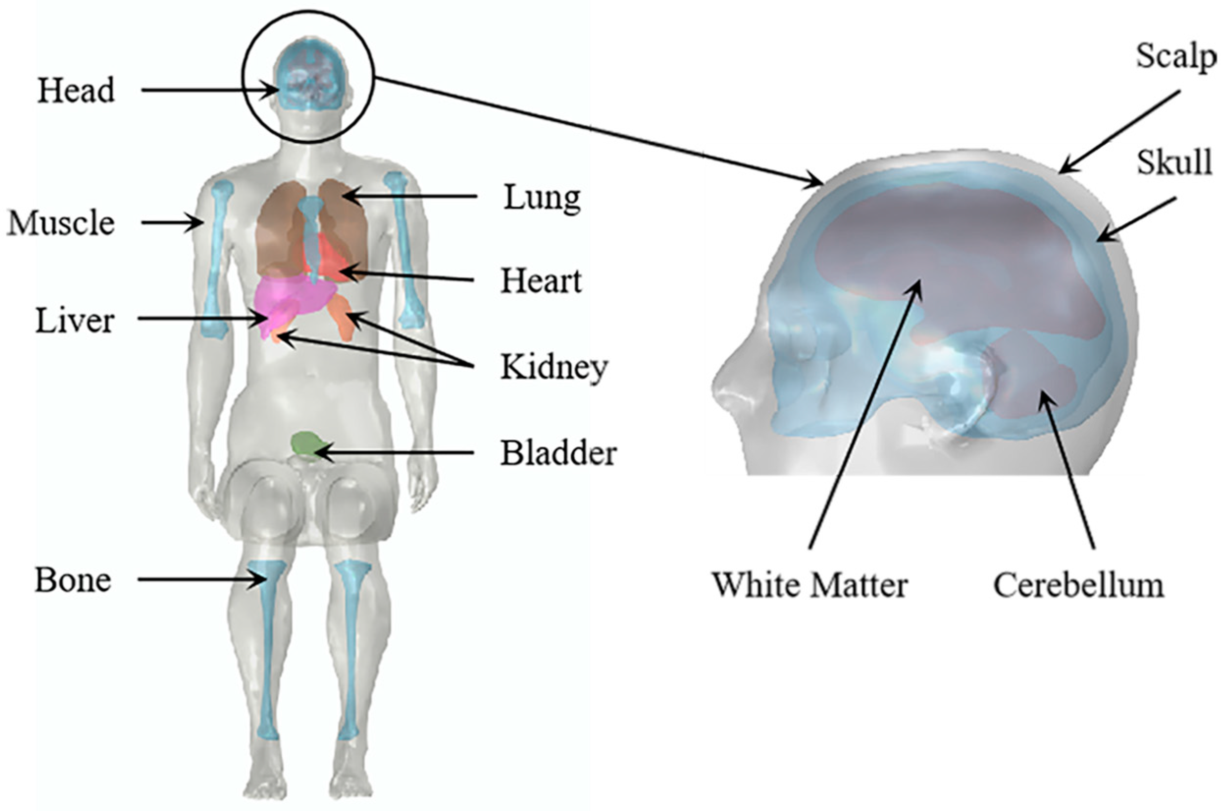
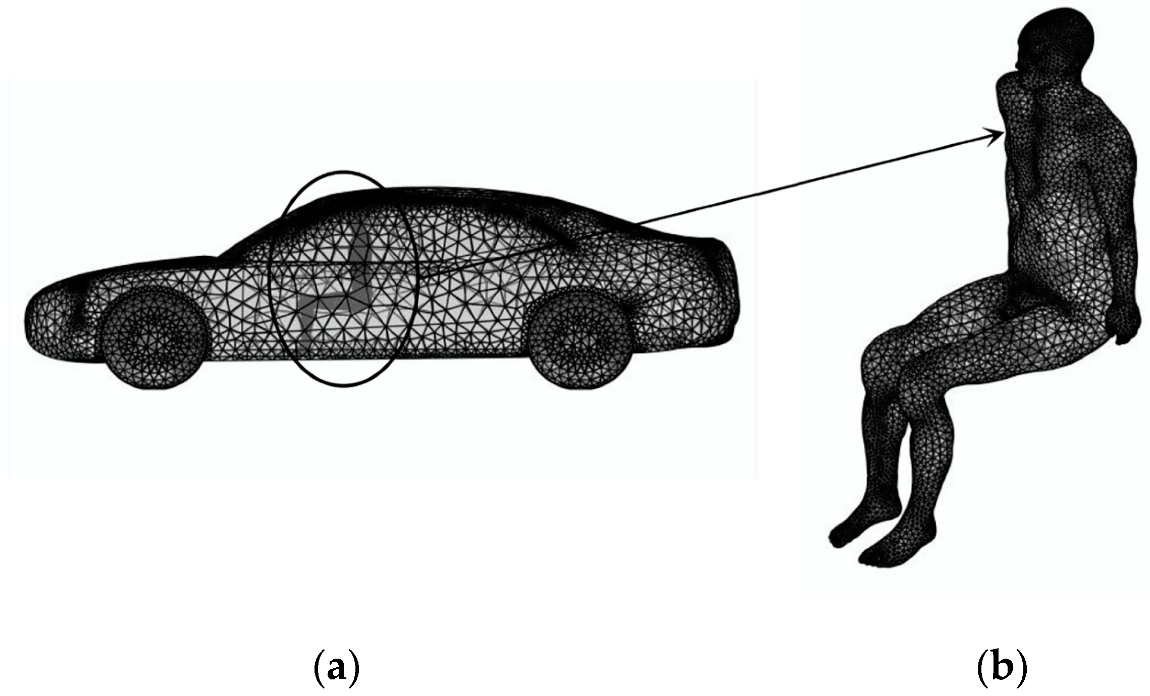
2.2. The Human Anatomy Model

The virtual family project is based on whole-body anatomical models with different ages and genders. Models for the project were originally developed for electromagnetic exposure assessment, specifically for the study of RF radiation from external sources. But these models have also been widely used in the field of medical research. The human model in this paper is derived from Duke, a real human anatomical model based on high-resolution MRI scanning in the virtual family project. Duke is a 34-year-old adult male with a standing height of 177 cm and a weight of 72.4 kg [37,38]. Based on the original anatomical model, several major organs and tissues, including muscle, bone, heart, lung, liver, kidney, bladder, skull, scalp, white matter, and cerebellum, were extracted from the standing model. Then, the standing model was modified to a sitting model in Materialize Magics 24.0 software, as shown in Figure 3. The modification process was mainly carried out to segment the standing human model from the joint parts and rotate the segmented model with the corresponding angle. Finally, the human sitting-posture model was synthesized by using the surface fitting function.
The dielectric parameters of tissues are generally calculated by the fourth-order Cole–Cole model [43,44], as described in Formula (1).
ε ^ r = ε r j ε r = ε r + n = 0 4   Δ ε n 1 + j ω τ n 1 α + σ i j ω ε 0
ε r is the relative dielectric constant at the optical frequency; n is the Debye dispersion number; Δ ε n is the relative dielectric constant increment; τ n is the center relaxation time (s); α is the time of relaxation distribution (0 ≤ α ≤ 1); ε 0 is vacuum dielectric constant (F/m); ω is the circular frequency (rad/s); σ i is conductivity (S/m).
The effects of electromagnetic exposure in several main tissues and organs are studied in this paper. Table 1 shows the dielectric parameters of the ten human tissues and organs at different frequencies.

2.3. Numerical Method

To solve the composite electromagnetic problem, the electromagnetic field of the PEV inverter was calculated in Comsol Multiphysics 6.0 with the coaction of the DC input, high-frequency inverter, and AC output current, meeting the following equations:
× H = J
B = × A
J = σ E + j ω D
E = j ω A
where H is the magnetic field strength (A m−1); J is the induced current density (A m−2); E is the electric field strength (V m−1); B is the magnetic flux density (T); D is the electric flux density (C m−2); A is the vector magnetic potential (Wb m−1); ω is the angular frequency; μ is the relative permeability (H m−1); and σ is the electrical conductivity (S m−1).
To achieve the best compromise between accuracy and computational efficiency, the inverter model was simplified, and only the most relevant parts were retained. The current was the only source of the magnetic field in the inverter. The simplified inverter was composed of two input DC wires, three inversion wires (simplified semiconductor model responsible for the inversion of the DC), and three output AC wires and encased in an aluminum alloy shell, as shown in Figure 4. In this study, the rated operating state of the inverter was used for numerical calculation, and the load was the 15 kW AC motor. So, the DC current in the DC wires was 34 A with a 350 V battery pack voltage, the AC current in the AC wires was 30 Arms with a frequency of 100 Hz, and the high-frequency pulse current in the inversion wires was 45 Arms with a frequency of 5.4 kHz.
Then, the three-dimensional geometric models (the human body, vehicle, and inverter models) were divided into tetrahedral meshes [45,46] in Comsol Multiphysics 6.0, which is a general numerical calculation tool for solving electromagnetic field problems. Based on Equations (2)–(5), the magnetic field interface under the AC/DC module of the Comsol Multiphysics 6.0 was adopted. The meshes of the human tissues and organs were divided more finely to improve the computing accuracy of the field distribution in different human tissues. In Comsol Multiphysics 6.0, the vehicle body model was divided into approximately 440,000 elements, and the human body model was divided into approximately 180,000 elements. The meshes of the calculation model are shown in Figure 5.
The entire calculation process was carried out on a computer with a main frequency of 2.5 GHz and 16 GB RAM, and the calculation time was approximately 2.5 h. The magnetic flux density near the inverter is shown in Figure 6. From the figure, we can see that the magnetic flux density in the central region of the inverter was the strongest, and the maximum magnetic flux density was about 1460 µT, while the general public exposure RL defined by the ICNIRP was 27 µT (the smaller of the 100 Hz and 5.4 kHz exposure limits) [10], meaning that the maximum magnetic flux density far exceeded the RL. However, as the spatial distance from the inverter increased, the magnetic flux density sharply decreased. Considering that the driver’s body would be exposed to this electromagnetic environment for a long time, in order to evaluate the safety of the driver’s body, the electromagnetic exposure doses in the different tissues and organs inside the driver’s body are calculated in this paper.

3. Results

The AC/DC calculation module of Comsol Multiphysics 6.0 was used to calculate the magnetic flux density (B-field) over the space occupied by the driver’s body, as well as the induced electric field (E-field) and the induced current density (J) in different tissues and organs. The calculated results were compared with the BRs and RLs defined by the ICNIRP. Thus, in this section, the exposure doses for the different tissues and organs are assessed.

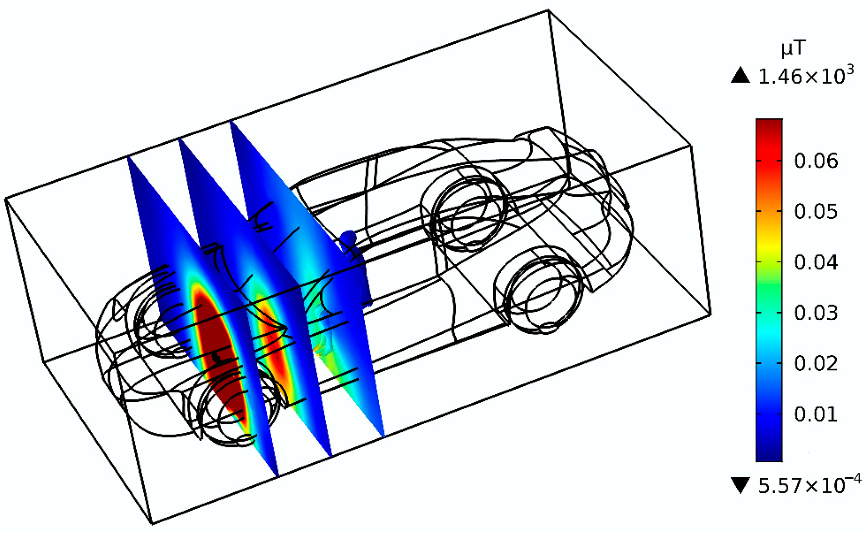
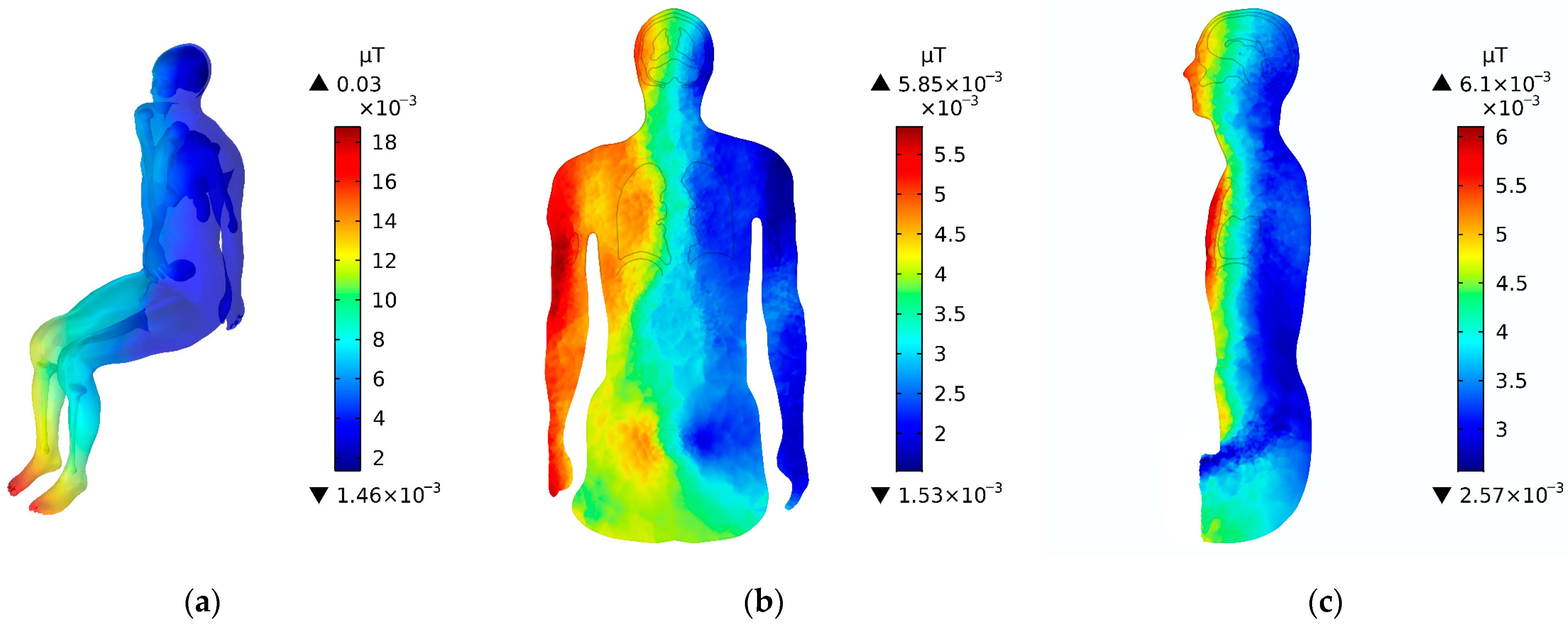
3.1. The B-Field in the Driver’s Body

For the magnetic fields, the permeability of human tissues and organs is the same as that of air, so the field in the tissues is the same as the external field. The human body does not significantly perturb the field. The safety guideline defined by the ICNIRP for magnetic flux density is the RL. So, we only calculated the B-field over the space occupied by the driver’s body in the paper through spatially averaging the B-field on the human body model. Figure 7a shows the B-field over the space occupied by the driver’s body with the influence of the electromagnetic fields. The stronger area of the B-field was mainly over the space occupied by the foot and crus area, whereas the other parts of the body were remarkably weaker than the foot region. The maximum B-field was about 0.03 μT, which is well below the RL of 27 μT (the smaller of the 100 Hz and 5.4 kHz exposure limits) defined by the ICNIRP for general public exposure [10]. The B-field of the frontal section and the sagittal section of the space occupied by the driver’s body are shown in Figure 7b and c, respectively. At this time, the B-field on the right side of the space occupied by the body was significantly stronger than that on the left side, and the B-field in the front side of the space occupied by the body was also obviously stronger than that of the back side. This is because the exposed source inverter was located in front of the driver’s body, and the distance from the exposed source inverter would directly affect the distribution of the B-field.

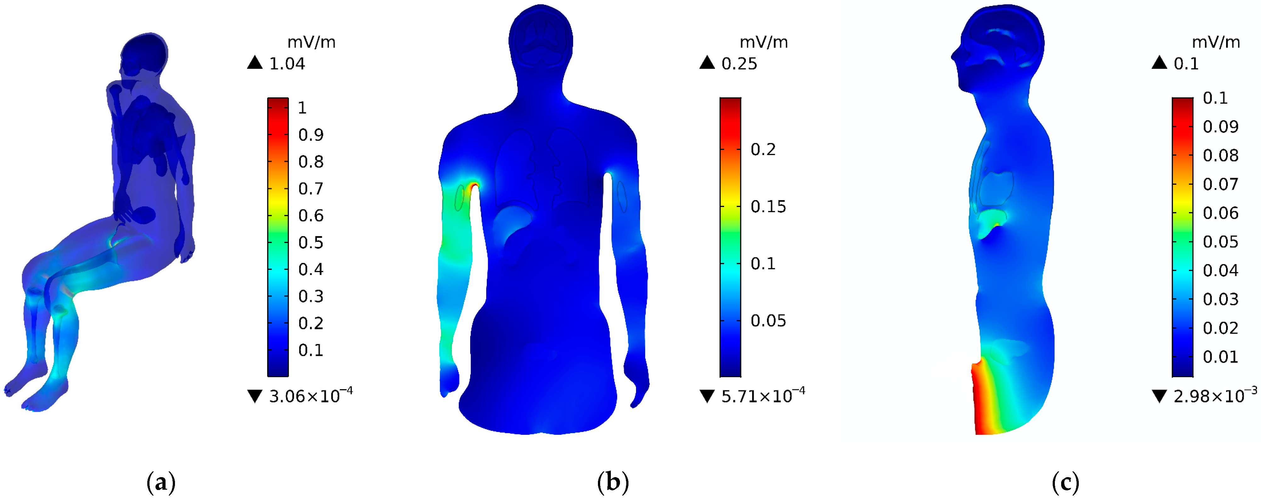
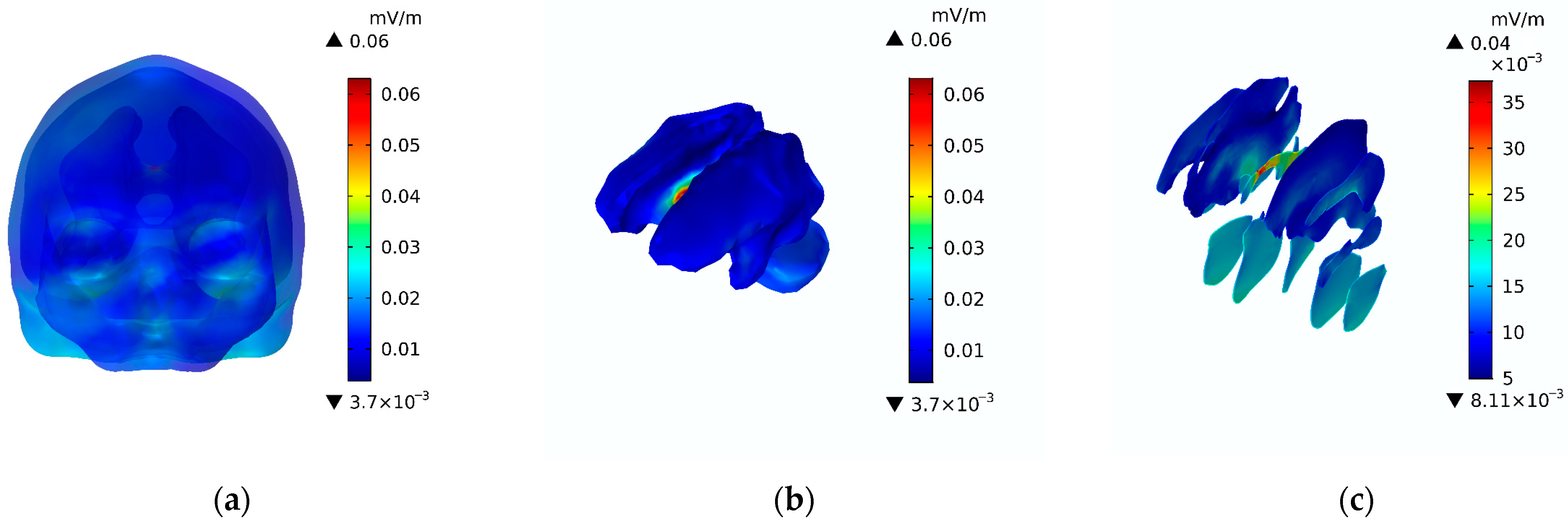
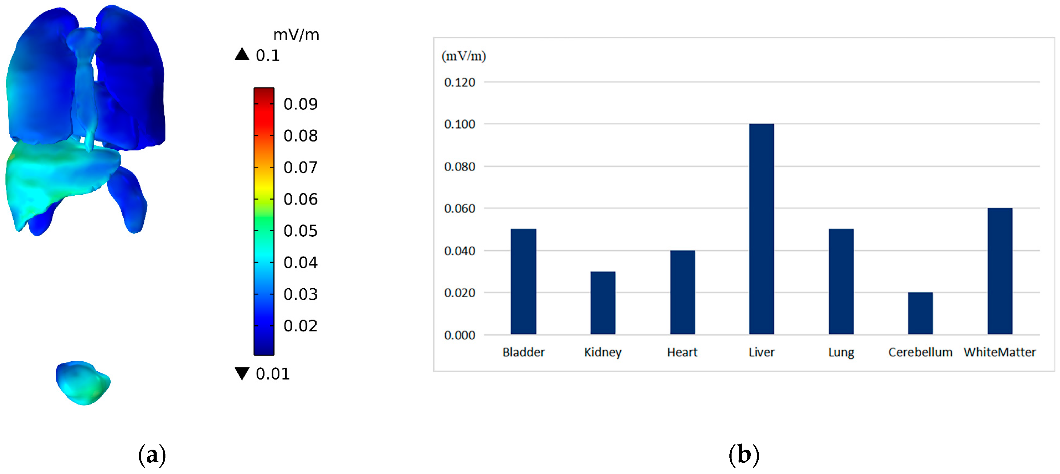
3.2. The E-Field in the Driver’s Body

The induced electric field in the human tissues were averaged over a small continuous tissue volume with a volume of 2 mm × 2 mm × 2 mm. Figure 8a shows the E-field in the driver’s body. The larger area of the electric field was predominately located near the legs; the other parts of the body were significantly weaker than the leg area. The maximum E-field was about 1.04 mV/m, which is well below the BR of 400 mV/m (the smaller of the 100 Hz and 5.4 kHz exposure limits) defined by the ICNIRP for general public exposure in the trunk [10]. Figure 8b and c shows the E-field in the frontal and sagittal sections of the driver’s body, respectively. The E-field on the right arm was stronger than that of other parts, and the maximum value was 0.25 mV/m. The E-field was also related to the distance to the inverter; the closer the distance to the inverter, the stronger the E-field.
Figure 9a shows the E-field in the driver’s head. There was no significant difference in E-field in the scalp, skull, and brain of the human head. The E-field was significantly below the BR of 40 mV/m (the smaller of the 100 Hz and 5.4 kHz exposure limits) defined by the ICNIRP for general public exposure in the central nervous system (CNS) [10]. Figure 9b and c show the E-field inside the brain tissues and in different sections of the brain tissues, respectively. As shown, the large area of the E-field in the brain is in the cerebellum. The distribution was also affected by the spatial distance of the cerebellum to the inverter and the dielectric parameters of the cerebellum.
Figure 10a,b show the E-field in the main organs and a comparison of the maximum E-field in different organs, respectively. As shown, the E-field in the liver was significantly larger, with the maximum being approximately 0.1 mV/m. The maximum E-field values in the kidney and heart were approximately 0.03 and 0.04 mV/m, respectively. The distribution characteristic was not only affected by the distance from the inverter but also related to the dielectric parameters of different organs.

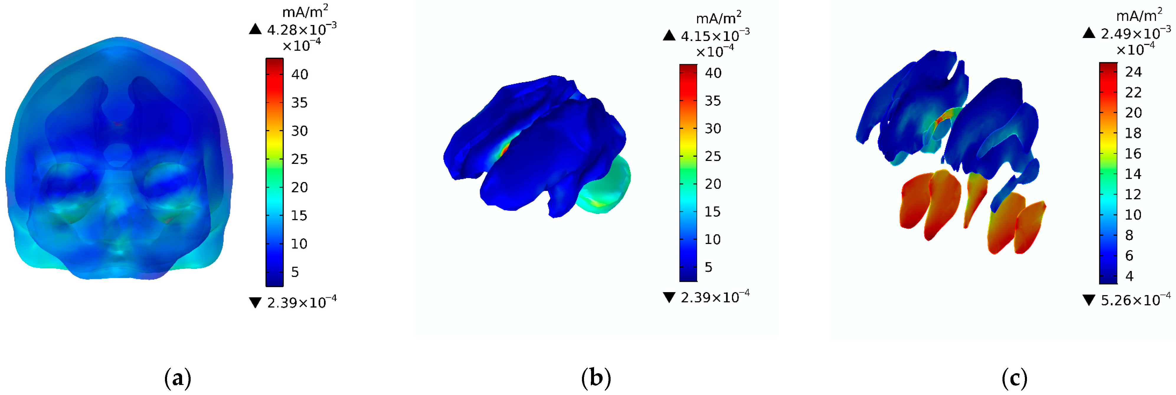
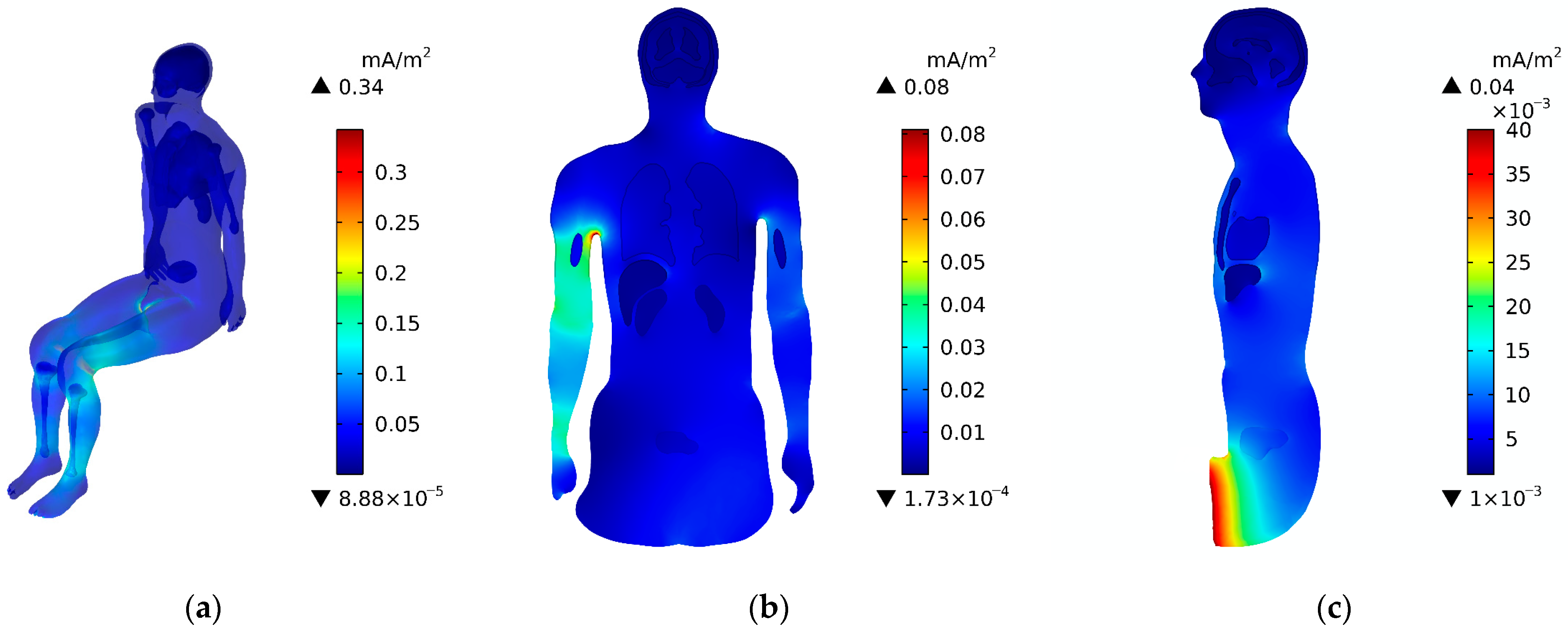
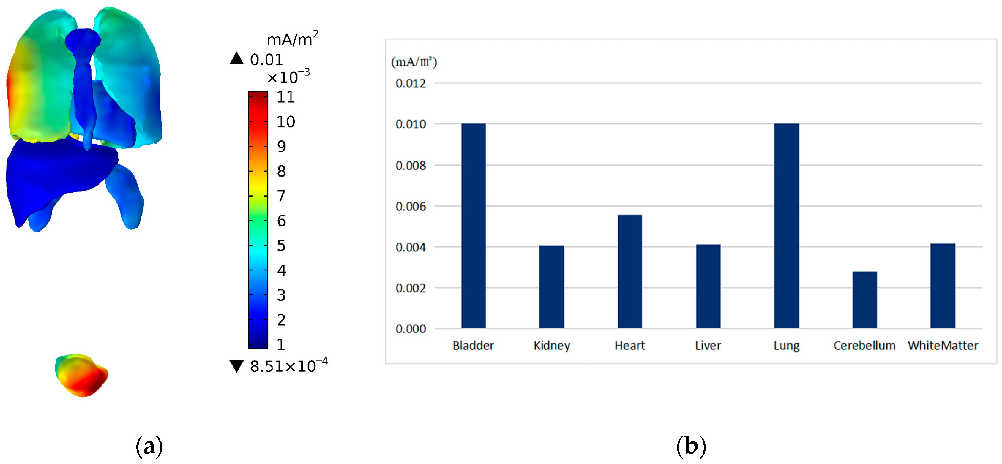
3.3. The J in the Driver’s Body

Figure 11a shows the induced current density (J) in the driver’s body. The larger area of the J was mainly located in the legs, and the other parts of the body were significantly smaller than that in the leg area. The maximum J in the legs was about 0.34 mA/m2. Figure 11b and c show the J in the frontal and sagittal sections of the driver’s body, respectively. The maximum J was near the right arm and the thigh, and the maximum values were 0.08 mA/m2 and 0.04 mA/m2. The closer the distance to the inverter, the stronger the induced current density.
The J in the head is shown in Figure 12a. The figure shows no evident difference in the distribution of the J in the scalp, skull, and brain tissues (white matter and cerebellum). The J in the cerebellum was slightly stronger than that in white matter. Figure 12b,c show the J in the brain and different sections of the brain tissue, respectively. As shown, the J in the cerebellum was larger than that in the white matter, and the maximum J in the cerebellum was approximately 2.49 × 10⁻³ mA/m2.
In addition, Figure 13a,b show the J in the main organs of the driver’s body and a comparison of the maximum J in the different organs, respectively. As shown, the value of the J in the bladder and lung was larger, whereas that in the other organs was smaller. The maximum value was approximately 0.01 mA/m2. The J was also affected by the distance to the inverter and the dielectric parameters of different organs.

4. Discussion

In recent years, with the continuous development of PEVs, the electrical devices inside these types of vehicles are becoming more and more complex. The electromagnetic exposure of these electrical devices to the passenger when driving has gradually attracted extensive attention. To calculate the distribution of the electromagnetic exposure doses in different organs and tissues of the real human body, for this paper, a real human model with 11 organs and tissues (muscle, bone, heart, lung, liver, kidney, bladder, skull, scalp, white matter, and cerebellum) was built based on the real human anatomy model in the human virtual family project. The inverter of the PEV served as the exposure source, and an equivalent electromagnetic environment model was established in the finite element software Comosol Multiphysics 6.0. The level of electromagnetic exposure that the driver was subjected to was calculated, as was the distribution of the B-field over the space occupied by the driver’s body and the E-field and J in the driver’s trunk, head, and main organs. The results show that the distribution of the B-field over the space occupied by the driver’s body and the E-field and J in the driver’s body were affected by the spatial distance to the exposure source: the PEV inverter. The farther the distance, the weaker the fields. Specifically, due to the different dielectric properties of the different tissues and organs, the values of the E-field and the J in the different tissues also show different distribution characteristics.
In addition, compared with the previous studies, the main innovative aspects of this paper include the fact that a PEV inverter was used as the electromagnetic exposure source and the electromagnetic dosimetry method was adopted to calculate the electromagnetic exposure levels of different organs and tissues in the driver’s body. The results of this study could supplement further studies on human bodies being subjected to electromagnetic exposure inside PEVs. Table 2 shows a comparison between the results of this paper and some existing studies.
In 1998, the ICNIRP evaluated the safety of electromagnetic exposure to time-varying electric and magnetic fields for frequencies below 100 kHz based on the J in the human body for their BRs. In 2010, the ICNIRP revised the time-varying electric field and magnetic field exposure limits for frequencies below 100 kHz and conducted an electromagnetic exposure safety assessment based on the E-field values inside the human body for their BRs. So, it is worth comparing the E-field with the BR outlined by the ICNIRP. The maximum E-field in the driver’s trunk and CNS were about 1.04 mV/m and 0.06 mV/m, respectively, which are well below the BRs defined by the ICNIRP for the human trunk and CNS for general public exposure. The maximum B-field over the space occupied by the driver’s body was about 0.03 μT, which is also well below the RL defined by the ICNIRP for general public exposure. However, due to the fact that the human body is a good conductor, when the human body is in a time-varying magnetic field environment, according to Faraday’s law of electromagnetic induction, an induced electric field and corresponding induced current will be generated within the human body. The J in the driver’s body was also calculated in this study. The maximum J in the driver’s trunk was about 0.34 mA/m2, and the maximum value in the CNS was 4.28 × 10⁻³ mA/m2.

5. Conclusions

Based on the numerical results, we found that although the B-field in the central region of the inverter exceeds the reference level of the ICNIRP for general public exposure, when the distance from the inverter is increased, the B-field values sharply decrease. The maximum B-field over the space occupied by the driver’s body and the E-field in the driver’s trunk and CNS are all below the exposure limits defined by the ICNIRP for general public exposure. The electromagnetic environment generated by the inverter adopted in this study (12 kW, Semikron, Germany), at its rated state in the paper, is therefore safe and would not affect the PEV driver’s health. Additionally, the results of this study could effectively supplement research regarding the electromagnetic environment of PEVs and provide references for the formulation of industry standards for electromagnetic exposure and the design of vehicles that are safe in terms of electromagnetic exposure.

Author Contributions

Conceptualization, X.D. and M.L.; Methodology, X.D.; Investigation, X.D.; Writing—Original Draft, X.D. and Y.G.; Calculation, Y.G.; Data analysis, Y.G.; Funding Acquisition, X.D. and M.L.; Supervision, X.D. and M.L. All authors have read and agreed to the published version of the manuscript.

Funding

This research was funded by the Natural Science Foundation of Gansu Province, China (Grant No. 20JR10RA217, Grant No. 23JRRA889) and 2023 Outstanding graduate student “Innovation Star” project in Gansu Province (2023CXZX-552).

Institutional Review Board Statement

Not applicable.

Informed Consent Statement

Not applicable.

Data Availability Statement

The data that support the findings of this study are available from the corresponding author upon reasonable request. The data are not publicly available due to privacy.

Acknowledgments

The authors would like to thank the technical team of the Key Laboratory of Opto-Electronic Technology and Intelligent Control of the Ministry of Education, Lanzhou Jiaotong University for their technical support.

Conflicts of Interest

The authors declare no conflict of interest.

References

  1. Bai, M.; Zhang, M.Y.; Wang, X.C. Policies and Trends of Global New Energy Vehicle Industry Development in the Context of Carbon Neutrality. Inf. Technol. Stand. 2021, 444, 13–20. [Google Scholar]
  2. Li, Q.M. The Shift from “policy-oriented” to “consumer-oriented” in the Pure Electric Vehicle Industry. Intell. Connect Veh. 2023, 27, 78–80. [Google Scholar]
  3. Hong, J.C.; Liang, F.W.; Yang, J.S.; Li, K.R. New Energy Vehicle Industry and Technology Development Status. Sci. Technol. Rev. 2023, 41, 49–59. [Google Scholar] [CrossRef]
  4. Wang, J.; Zeng, Z.; Tang, G.D.; Ou, K.H.; Wang, L.; Yu, Y. Mission Profile Oriented Lifetime Assessment of SiC Inverter for Electric Vehicle Application. Proc. CSEE 2021, 41, 2507–2519. [Google Scholar] [CrossRef]
  5. Martyushev, N.V.; Malozyomov, B.V.; Khalikov, I.H.; Kukartsev, V.A.; Kukartsev, V.V.; Tynchenko, V.S.; Tynchenko, Y.A.; Qi, M. Review of Methods for Improving the Energy Efficiency of Electrified Ground Transport by Optimizing Battery Consumption. Energies 2023, 16, 729. [Google Scholar] [CrossRef]
  6. Li, X.; Shu, X.; Shen, J.; Xiao, R.; Yan, W.; Chen, Z. An On-Board Remaining Useful Life Estimation Algorithm for Lithium-Ion Batteries of Electric Vehicles. Energies 2017, 10, 691. [Google Scholar] [CrossRef]
  7. Moreno-Torres, P.; Lafoz, M.; Blanco, M.; Arribas, J.R. Passenger Exposure to Magnetic Fields in Electric Vehicles In Modeling and Simulation for Electric Vehicle Applications. In Modeling and Simulation for Electrical Vehicle Applications; Fakhfakh, M.A., Ed.; InTech: Rijeka, Croatia, 2016; pp. 50–51. [Google Scholar]
  8. Pang, X.F. Bioelectromagnetic, 1st ed.; National Defense Industry Press: Beijing, China, 2008; pp. 135–152. [Google Scholar]
  9. IEEE International Committee on Electromagnetic Safety. IEEE Standard for Safety Levels with Respect to Human Exposure to Electric, Magnetic, and Electromagnetic Fields, 0 Hz to 300 GHz; IEEE: Piscataway, NJ, USA, 2019. [Google Scholar] [CrossRef]
  10. ICNIRP. Guidelines for Limiting Exposure to Time-varying Electric and Magnetic Fields (1 Hz to 100 kHz). Health Phys. 2010, 99, 818–836. [Google Scholar] [CrossRef]
  11. ICNIRP. Guidelines for Limiting Exposure to Electromagnetic Fields (100 kHz to 300 GHz). Health Phys. 2020, 118, 483–524. [Google Scholar] [CrossRef]
  12. Kheifets, L.; Ahlbom, A.; Crespi, C.M.; Draper, G.; Hagihara, J.; Lowenthal, R.M.; Mezei, G.; Oksuzyan, S.; Schüz, J.; Swanson, J.; et al. Pooled Analysis of Recent Studies on Magnetic Fields and Childhood Leukaemia. Br. J. Cancer 2010, 103, 1128–1135. [Google Scholar] [CrossRef]
  13. Li, C.Y.; Thériault, G.; Lin, R.S. Epidemiological Appraisal of Studies of Residential Exposure to Power Frequency Magnetic Fields and Adult Cancers. Occup. Environ. Med. 1996, 53, 505–510. [Google Scholar] [CrossRef]
  14. Liu, T.; Wang, S.; He, L.; Ye, K. Chronic Exposure to Low-intensity Magnetic Field Improves Acquisition and Maintenance of Memory. Neuroreport 2008, 19, 549–552. [Google Scholar] [CrossRef]
  15. Cichoń, N.; Bijak, M.; Miller, E.; Saluk, J. Extremely Low Frequency Electromagnetic Field (ELF-EMF) Reduces Oxidative Stress and Improves Functional and Psychological Status in Ischemic Stroke Patients. Bioelectromagnetics 2017, 38, 386–396. [Google Scholar] [CrossRef]
  16. Moya Gómez, A.; Font, L.P.; Brône, B.; Bronckaers, A. Electromagnetic Field as a Treatment for Cerebral Ischemic Stroke. Front. Mol. Biosci. 2021, 8, 742596. [Google Scholar] [CrossRef]
  17. Li, C.; Lin, J.; Lei, J.; Wu, T.; Qi, D.; Chen, R. Dosimetry Assessment for Human Exposure to Extremely Low Frequency Magnetic Fields in the Electric Vehicles. In Proceedings of the 12th International Symposium on Antennas, Propagation and EM Theory (ISAPE), Hangzhou, China, 3–6 December 2018. [Google Scholar] [CrossRef]
  18. Sztafrowski, D.; Winiarz, J. Electromagnetic field in electric and hybrid cars. In Journal of Physics: Conference Series; IOP Publishing: Bristol, UK, 2021; Volume 2408, p. 012018. [Google Scholar] [CrossRef]
  19. Bae, H.; Park, S.W. Assessment of the Electromagnetic Radiation Exposure at EV Charging Facilities. Sensors 2023, 23, 162. [Google Scholar] [CrossRef]
  20. Tell, R.A.; Kavet, R. Electric and Magnetic Fields <100 kHz in Electric and Gasoline-Powered Vehicles. Radiat. Prot. Dosim. 2016, 172, 541–546. [Google Scholar] [CrossRef]
  21. Wyszkowska, J.; Szczygiel, M.; Trawinski, T. Static Magnetic Field and Extremely Low-frequency Magnetic Field in Hybrid and Electric Vehicles. Prz. Elektrotech. 2020, 96, 60–62. [Google Scholar] [CrossRef]
  22. Atanasova, G.L.; Gârdan, D.A.; Gârdan, I.P. Experimental Assessment of Electromagnetic Fields Inside a Vehicle for different Wireless Communication Scenarios: A New Alternative Source of Energy. Energies 2023, 16, 5622. [Google Scholar] [CrossRef]
  23. Jeladze, V.B.; Nozadze, T.R.; Tabatadze, V.A.; Petoev-Darsavelidze, I.A.; Prishvin, M.M.; Zaridze, R.S. Electromagnetic Exposure Study on a Human Located Inside the Car Using the Method of Auxiliary Sources. J. Commun. Technol. Electron. 2020, 65, 457–464. [Google Scholar] [CrossRef]
  24. Ding, P.P.; Bernard, L.; Pichon, L.; Razek, A. Evaluation of Electromagnetic Fields in Human Body Exposed to Wireless Inductive Charging System. IEEE Trans. Magn. 2014, 50, 1037–1040. [Google Scholar] [CrossRef]
  25. Xu, G.Z.; Li, C.X.; Zhao, J.; Zhang, X. Electromagnetic Environment Safety Study of Wireless Electric Vehicle Charging. Trans. China Electrotech. Soc. 2017, 32, 152–157. [Google Scholar] [CrossRef]
  26. Park, S.W. Evaluation of Electromagnetic Exposure during 85 kHz Wireless Power Transfer for Electric Vehicles. IEEE Trans. Magn. 2018, 54, 1–8. [Google Scholar] [CrossRef]
  27. Wang, Q.D.; Li, W.L.; Kang, J.W.; Wang, Y.C. Electromagnetic Safety Evaluation and Protection Methods for a Wireless Charging System in an Electric Vehicle. IEEE Trans. Electromagn. Compat. 2019, 61, 1913–1925. [Google Scholar] [CrossRef]
  28. Mou, W.T.; Lu, M. Research on Electric Vehicle Electromagnetic Protection Considering Radiation of Two Wireless Chargers. WEVJ 2022, 13, 95. [Google Scholar] [CrossRef]
  29. Guo, H.T.; Chen, Y.M.; Li, Y.; Zhou, W.; Xu, W.H.; Pang, L. Electrospun Fibrous Materials and their Applications for Electromagnetic Interference Shielding: A review. Compos. Part A Appl. Sci. Manuf. 2021, 143, 106309. [Google Scholar] [CrossRef]
  30. Uddin, M.J.; Ullah, M.H.; Islam, S.Z. A Broadband Polarized Metamaterial Absorber Driven by Strong Insensitivity and Proximity Effects. IEEE Access 2021, 9, 131672–131684. [Google Scholar] [CrossRef]
  31. Uddin, J.; Shakib, M.N.; Islam, S.Z.; Hasan, M.M.; Ullah, H.; Rahman, M.A. A Scalable Power Splitter using High Sheet Polysilicon Resistor Suitable for RFIC Application. In Proceedings of the International Conference on Intelligent Technology, System and Service for Internet of Everything (ITSS-IoE), Hadhramaut, Yemen, 3–5 December 2022. [Google Scholar] [CrossRef]
  32. Tian, R.; Lu, M. Safety Assessment of Electromagnetic Exposure in High-Speed Train Carriage with Full Passengers. Ann. Work Expo. Health 2020, 64, 838–851. [Google Scholar] [CrossRef] [PubMed]
  33. Wang, Q.D.; Li, W.L.; Kang, J.W.; Wang, Y.C. Electromagnetic Safety of Magnetic Resonant Wireless Charging System in Electric Vehicles. In Proceedings of the 2017 IEEE PELS Workshop on Emerging Technologies: Wireless Power Transfer, Chongqing, China, 20–22 May 2017. [Google Scholar] [CrossRef]
  34. De Santis, V.; Giaccone, L.; Freschi, F. Influence of Posture and Coil Position on the Safety of a WPT System While Recharging a Compact EV. Energies 2021, 14, 7248. [Google Scholar] [CrossRef]
  35. Kos, B.; Valič, B.; Miklavčič, D.; Kotnik, T.; Gajšek, P. Pre- and Post-natal Exposure of Children to EMF Generated by Domestic Induction Cookers. Phys. Med. Biol. 2011, 56, 6149–6160. [Google Scholar] [CrossRef]
  36. Hardy, B.M.; Banik, R.; Yan, X.; Anderson, A.W. Bench to Bore Ramifications of Inter-subject Head Differences on RF Shimming and Specific Absorption Rates at 7T. Magn. Reson. Imaging 2022, 92, 187–196. [Google Scholar] [CrossRef]
  37. Haussmann, N.; Mease, R.; Zang, M.; Stroka, S.; Hensel, S.; Clemens, M. Efficient High-resolution Electric and Magnetic field Simulations Inside the Human body in the Vicinity of Wireless Power Transfer Systems with Varying Models. COMPEL 2023, 42, 903–913. [Google Scholar] [CrossRef]
  38. Gosselin, M.C.; Neufeld, E.; Moser, H.; Huber, E.; Farcito, S.; Gerber, L.; Jedensjö, M.; Hilber, I.; Gennaro, F.D.; Lloyd, B.; et al. Development of a New Generation of High-resolution Anatomical Models for Medical Device Evaluation: The Virtual Population 3.0. Phys. Med. Biol. 2014, 59, 5287–5303. [Google Scholar] [CrossRef]
  39. Niu, Z.Q.; Hou, J.Q.; Zhou, Y.J.; Wang, H.B.; Lu, Z.Y. The Bioelectromagnetics Dosimetry and Numerical Analysis of Electromagnetic Dose Absorbed by Human Body. Chin. J. Biomed. Eng. 2006, 25, 580–584+589. [Google Scholar] [CrossRef]
  40. Peng, Y.H. Morden Car Design; China Machine Press: Beijing, China, 2011. [Google Scholar]
  41. Jin, D.; Zhang, H.S.; Li, J.Q.; Jiang, J.J.; Wang, A. Research and Simulation of Three-phase Inverter Control Strategy. Res. Explor. Lab. 2022, 41, 114–118+217. [Google Scholar] [CrossRef]
  42. Moreno-Torres, P.C.; Lourd, J.; Lafoz, M.; Arribas, J.R. Evaluation of the Magnetic Field Generated by the Inverter of an Electric Vehicle. IEEE Trans. Magn. 2013, 49, 837–844. [Google Scholar] [CrossRef]
  43. Gabriel, C.; Gabriel, S.; Corthout, E. The Dielectric Properties of Biological Tissues: I. Literature Survey. Phys. Med. Biol. 1996, 41, 2231–2249. [Google Scholar] [CrossRef]
  44. Gabriel, S.; Lau, R.W.; Gabriel, C. The Dielectric Properties of Biological Tissues: II. Measurements in the Frequency Range 10 Hz to 20 GHz. Phys. Med. Biol. 1996, 41, 2251–2269. [Google Scholar] [CrossRef]
  45. Conchin Gubernati, A.; Freschi, F.; Giaccone, L.; Scorretti, R. Analysis of Numerical Artifacts Using Tetrahedral Meshes in Low Frequency Numerical Dosimetry. Appl. Sci. 2022, 12, 6526. [Google Scholar] [CrossRef]
  46. Diao, Y.L.; Rashed, E.A.; Giaccone, L.; Laakso, I.; Li, C.S.; Scorretti, R.; Sekiba, Y.; Yamazaki, K.; Hirata, A. Intercomparison of the Averaged Induced Electric Field in Learning-Based Human Head Models Exposed to Low-Frequency Magnetic Fields. IEEE Access 2023, 11, 38739–38752. [Google Scholar] [CrossRef]
Figure 1. The PEV model and the related dimensions: (a) PEV model; (b) relative position of the driver and inverter.
Applsci 14 00032 g001
Figure 2. Schematic diagram of inverter connection.
Applsci 14 00032 g002
Figure 3. Model of a human body in a seated position.
Applsci 14 00032 g003
Figure 4. The inverter of the PEV: (a) the inverter; (b) the simplified model of the inverter.
Applsci 14 00032 g004
Figure 5. Meshes of the model: (a) meshes of the whole model; (b) meshes of the human body.
Applsci 14 00032 g005
Figure 6. The distribution of the magnetic flux density near the inverter.
Applsci 14 00032 g006
Figure 7. Distributions of the B-field: (a) the B-field over the space occupied by the driver’s body; (b) the B-field over the frontal section of space occupied by the body; (c) and the B-field over the sagittal section of space occupied by the body.
Applsci 14 00032 g007
Figure 8. Distributions to the E-field: (a) the E-field in the driver’s body; (b) the E-field in the frontal section of the body; and (c) the E-field in the sagittal section of the body.
Applsci 14 00032 g008
Figure 9. Distributions of the E-field: (a) the E-field in the head; (b) the E-field in the brain tissues; and (c) the E-field in different sections of the brain tissues.
Applsci 14 00032 g009
Figure 10. Distributions of the E-field: (a) the E-field in different organs; and (b) the maximum E-field in different major organs.
Applsci 14 00032 g010
Figure 11. Distributions of the J: (a) the J in the driver’s body; (b) the J in the frontal section of the body; and (c) the J in the sagittal section of the body.
Applsci 14 00032 g011
Figure 12. Distributions of the J: (a) the J in the head; (b) the J in the brain tissues; and (c) the J in different sections of the brain tissue.
Applsci 14 00032 g012
Figure 13. Distributions of the J: (a) the J in different organs; (b) the maximum of J in different major organs.
Applsci 14 00032 g013
Table 1. Dielectric parameters of the different tissues and organs of the human body.
Tissues of
Human Model
Relative
Permeability
Relative
Permittivity
(100 Hz)
Electrical
Conductivity
(S/m) (100 Hz)
Relative
Permittivity
(5400 HZ)
Electrical
Conductivity
(S/M) (5400 HZ)
Bladder1192,8400.2112,4670.21
Bone1217,0300.0827910.08
White Matter11,667,7000.0619,7930.07
Cerebellum13,906,4000.1139,7200.13
Scalp145,2980.000529,9190.0015
Heart13,163,7000.09120,1700.14
Kidney13,518,1000.1065,2070.13
Liver1678,4700.0441,0510.05
Lung1567,0800.2161,1560.24
Muscle19,329,0000.2747,9820.34
Table 2. Comparison between the results of this study and those of other studies (with the relevant references listed).
References
(Exposure Source)
B (µT)
(Head Area)
E (mV/m)
(CNS)
Reference [17] (equivalent source)0.0400.20
Reference [23] (wireless charging coil)0.0030.30
This paper (inverter)0.0050.18
Disclaimer/Publisher’s Note: The statements, opinions and data contained in all publications are solely those of the individual author(s) and contributor(s) and not of MDPI and/or the editor(s). MDPI and/or the editor(s) disclaim responsibility for any injury to people or property resulting from any ideas, methods, instructions or products referred to in the content.

