Featured Application
Complementary energy principle with mixed variables, Complex underground space structure with the Track Panel Tunnel.
Abstract
The control parameter of the complex underground space structure with the Track Panel Tunnel and wall columns was studied. An analysis method of the control parameter was established based on the complementary energy principle with mixed variables. The general analytical solution of the structure under the trapezoidal load was obtained. Then, the correctness of the solution was verified by two-dimensional finite element simulation. The three-dimensional global model is built to analyze models with different story heights, the distance of two adjacent wall columns, and the thickness of the earth covering; the consequences prove the assumptions’ rationality and the engineering applicability of the analytical solution. The sensitive region of the control parameter is found through the analytical solution, which is meaningful in determining the reasonable stiffness ratio of column and beam for structural design optimization with cost savings. It can be the reference for complex underground space engineering designs.
1. Introduction
The construction of large-scale subway stations and tunnel integration projects further promotes the research of complex underground structure engineering. The rationality of design, durability of structures, and safety of construction [1,2] have been widely concerned. Different soil parameters, including the soil–water characteristic [3], nonlinear stress–strain relationship of soils [4], and structured soil types [5], can have an impact on the design of subway stations and the shield construction [6]. This paper will analyze the control parameters of the underground space structure with the Track Panel Tunnel and wall columns using the complementary energy principle with mixed variables.
The track panel, shown in Figure 1, is assembled by two rails on the ground first and hoisted to the metro station for track laying in the process of metro construction. Hence, using the central station’s top plates with one or several large openings offers an engineering solution for track laying called the Track Panel Tunnel (TPT) [7], as shown in Figure 2. In addition, the openings are usually set right above the metro line for safety and high hoisting efficiency. As the length of each rail section is almost 25 m, the length and the width of the net size of openings are about 27~30 m and 3.5~5 m, respectively. Therefore, the number of openings is determined according to the needs of the track panel lifting.
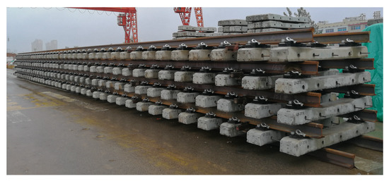
Figure 1.
Picture of track panel.
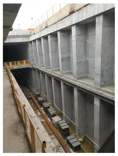
Figure 2.
Picture of metro station with reserved large-size openings.
Side walls near the openings lose the support of the structural slabs and become the weak region [8]. The combination of frame beams around the openings and wall columns of the side wall is widely used in metro station design to improve the out-of-plane stiffness of the structure [9,10,11,12]. The system can resist high water and soil pressures on the outside side walls and satisfy the normal usage requirements of the metro station [1]. The maximal bending moment at the bottom of the column in the middle of the Track Panel Tunnel (TPT) opening plays a controlling role in the design of the cross-section size and the reinforcement area of the wall column [13]. There are two extreme tendencies in determining the position of the opening in engineering projects generally. One is setting the opening close to the side wall simply for the convenience of track panel lifting. However, such an approach will commonly make the stiffness of the frame beam insufficient, as the opening limits its height and results in an enormous waste of the cross section or the quantity of reinforcement of the wall column further. The other is establishing the opening away from the side wall for effectively supporting without considering the convenience of lifting [14]. The lack of theoretical research about the relationship between the controlling bending moment and the position of reserved openings is due to a weak understanding of this changing law and makes the design of TPT difficult in balancing the convenience of using and the safety and economy of designing.
The complementary energy principle with mixed variables is an unconditional variational principle based on the classical minimum complementary energy principle [15], which takes stress and displacement as the auto-variable functions [16]. The complex structural system is reduced to a variational problem of finding the extreme value of the function through the energy conservation idea. It applies to analyzing complex structural systems coupled with various structural components with different performances [17,18].
This paper draws out the mechanical model for calculating the control parameter of the TPT structure system under the premise of appropriate assumptions. It derives the general analytical solution of the control bending moment for the TPT column under trapezoidal loadings by the complementary energy principle with mixed variables. Then, it verifies the correctness of the solution by the two-dimensional finite element simulation and proves the rationality of the assumption and the engineering applicability of this solution by three-dimensional global model analysis. It obtains a control parameter of the wall column about the column–beam stiffness ratio after an in-depth analysis of the structural stress mechanism through the analytical result. This parameter is crucial to determine the reasonable column–beam stiffness ratio and balance the openings’ convenience and the structure’s safety and economy.
2. Theoretical Analysis of the Control Parameter of Complex Underground Space Structure with Reserved Large-Size Openings
2.1. Mechanical Model and Basic Assumptions
We take the side wall near the opening as the research object, as shown in Figure 3. There are effective restraints on the side wall at the end, considering the reinforcement of hidden columns at the side wall’s entrance and the side wall’s box-section form. Therefore, we can simplify the research object’s restraint boundaries as three fixed boundaries and one free boundary. Currently, the system comprises three members: the wall columns, the walls, and the frame beams.
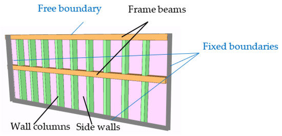
Figure 3.
Side walls of the opening.
In the analysis of underground structures, the boundary problem of soil–structure interaction is also a crucial factor affecting the accuracy of structural calculations [19]. The soil properties, changes in the groundwater level, and ground loads can all impact the underground structure. The commonly used calculation methods for underground systems include the load-structure and stratum-structure methods [20]. The load-structure method considers that the action of soil on underground systems is only to generate loads acting on them, including active soil pressure and passive soil resistance. It is commonly used in theoretical analysis of the static characteristics of underground structures and is currently widely used in engineering. The commonly used elastic methods for underground systems, such as the elastic continuous frame method, assumed resistance method, and elastic foundation beam method, are based on this, and this paper considers the earth pressure as a linearly distributed load acting on the side wall based on the load-structure method.
Only the earth pressure load factor needs to be adjusted when encountering changes in the groundwater level or ground surcharge. Moreover, the soil can be considered homogeneous in theoretical analysis, which has good applicability for the buried depth of the underground space structure of about 15 m. Now, external loads such as lateral water and soil pressure outside the side wall are applied to the system. Side walls, beams, and wall columns next to the soil should meet the serviceability requirements (crack width control), satisfying the antiseepage requirement, i.e., the system can be considered elastic. Therefore, the bending moment at the bottom of the wall column in the middle of the large opening is the control bending moment in the structural design and the necessary condition for calculating the structural section size and reinforcement. The theoretical analysis aims to obtain the control bending moment of the wall column using the sub-zone and sub-item mixed-energy principle.
The system can be divided into different sub-zones, i.e., the i-th wall column belongs to the (I = 1 − n) zone, the j-th wall belongs to the (j = 1 − n) zone, and the k-th frame beam belongs to the (k = 1 − 2) zone. According to the complementary energy principle with mixed variables, the complementary energy functional of the system can be expressed as Equation (1).
where , , and represent the sum of the complementary energy functional of wall columns, walls, and frame beams, respectively.
, , and represent the sum of additional complementary energy functional on the interface of the adjacent partition between wall columns and their adjacent wall, wall columns and their adjacent frame beams, and frame beams and their adjacent walls, respectively.
The complementary energy of any region is expressed as Equation (2).
where represent any zone of wall columns, walls, and beams, respectively.
- represents the possible static stress of the elastomer in the specified zone.
- represents the generalized flexibility of the specified zone and satisfies the stress–strain relationship .
- is the static boundary condition on the free boundary and satisfies the equation of .
- where is the surface force on the free boundary.
The complementary energy functional on the boundary of adjacent zones a and b can be expressed as Equation (3).
where represents the boundary of two zones a and b.
represents the displacement vector on the boundary of zone a.
Furthermore, we can regard the frame beam as the elastic support of the wall column in the elastic deformation range because of the coordinated deformation of the frame beam and the wall column at their beam–column joint. In addition, the stiffness of flexible support depends on the resistance to deformation of frame beams. Therefore, the system comprises two parts of side walls and wall columns, with elastic support constraints of frame beams at the beam–column joint. The complementary energy functional of the system can be simplified as Equation (4).
According to the sub-zone complementary energy principle, the complementary energy functional of the system satisfies Equation (5) as long as it meets all the equilibrium equations both in the elastic sub-zones and at their interfaces.
where represents the variational operation.
In addition, the side wall’s restraint on the adjacent wall column is weak enough to neglect, since the rigidity of the side wall is far less than that of the wall column. The variation of additional complementary energy functional on the interface between the wall and the wall column is approximately zero, shown as Equation (6).
The above assumption ignores the interaction between walls and columns. Then, we bring Equation (6) into Equation (5) and obtain Equation (7).
Due to the coordination of overall deformation of the system, the variation of residual energy of each wall column is positive or negative under external load, so the residual energy variation of each pillar is zero, shown as Equation (8).
The frame beam’s deformation is the largest in the middle of the hole, so the bearing reaction of the wall column in the middle of the hole is the largest, as shown in the simplified model of Figure 4. The corresponding bending moment at the bottom of this wall column is the maximum value of all wall columns, and it is the control parameter for the structural design of the wall column. Therefore, the middle wall column of the hole is the crucial point of this research, and it can be further simplified as an elastic column, as shown in Figure 5.
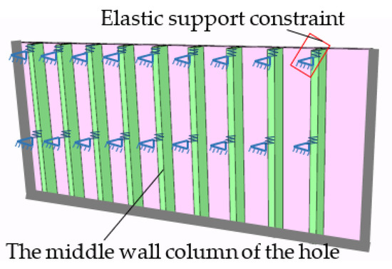
Figure 4.
The simplified system composed of wall columns and walls.
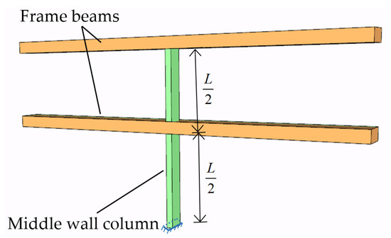
Figure 5.
The middle wall column of the hole.
Because of the actual functional requirements of the metro station, there is usually little difference in height between the two layers [21]. The following basic assumptions are made to facilitate the analysis and derivation:
- The influence of wall thickness is ignored;
- The cross sections of the upper and lower frame beams are the same;
- The heights of the upper and lower layers of the station are the same;
- The connection between the wall column and the bottom plate of the station is rigid. The beam and the end of the wall are also rigidly connected.
- The bending stiffness of the wall column is , the shear stiffness is , and the compressive modulus of elasticity is .
- The rigidity of elastic support provided by the frame beam is .
On condition that the rigid ability of elastic support depends on the frame beam’s deformation-resistant capacity, the displacement of the fixed-supported beam at both ends under the action of unit concentrated force in the middle can be expressed as Equation (9), and the free-body diagram is shown in Figure 6.
where
is the elastic modulus of the frame beam.
is the section moment of the frame beam.
is the calculated length of the frame beam.

Figure 6.
Free-body diagram of the fixed-supported beam.
Figure 6.
Free-body diagram of the fixed-supported beam.

The stiffness of elastic support is the reciprocal of its flexibility; that is, the reciprocal of displacement under the action of the unit concentrated force is calculated in Equation (10), and the mechanical model of the wall column is shown in Figure 7, in which the constraints of the column is simplified as a fixed constraint at the bottom and elastic bearings both in the middle and on the top. The deformation of the wall column depends on its deformation characteristics and elastic support constraints.
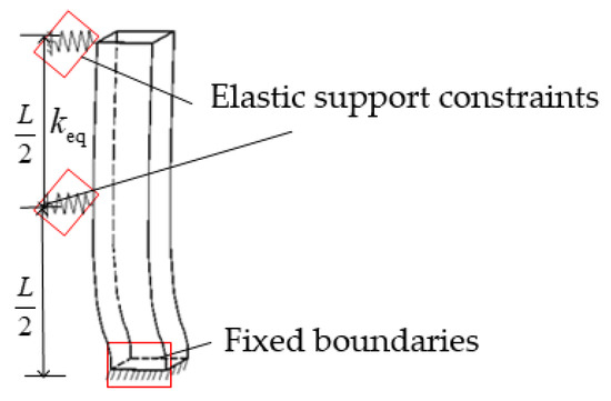
Figure 7.
Mechanical model of wall column.
2.2. Theoretical Analysis of the Control Bending Moment at the Bottom of the Column
Considering various loads such as soil weight [22], water pressure, and surface vehicle loads [23,24], we can simplify the distribution of these pressures on the side walls of the underground metro stations as the trapezoidal distributed load [25]. In addition, we can facilitate the control bending moment of the target-wall column as a mechanical problem in which the column is fixed-supported at the end and elastic-supported both in the middle and on the top under a trapezoidal distributed load with a specific gradient [26].
Based on the Code for metro design, the impermeability grade of the side wall of the metro station is P10, and the tolerated range of deformation is 0.2 mm, accordingly. Under this condition, the inner forces of side walls satisfy the linear superposition principle when the element is in the elastic stage [27]. Therefore, the trapezoidal distributed load can be decomposed into uniformly distributed load q and triangularly distributed load Q, as shown in Figure 8.
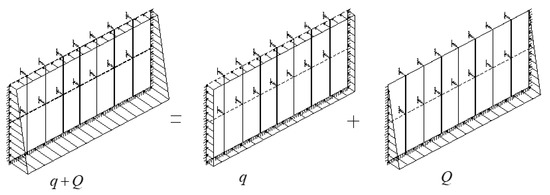
Figure 8.
Simplified calculation model of wall column.
Under the uniformly distributed load, elastic supports at the top and the middle can be removed and replaced by unknown forces X1 and X2, respectively, as shown in Figure 9. Thus, the statically indeterminate structure is simplified as a statically determinate structure with additional unknown forces X1 and X2 [28], and then the basic structure of force method under the uniformly distributed load is obtained (shown as Figure 9).
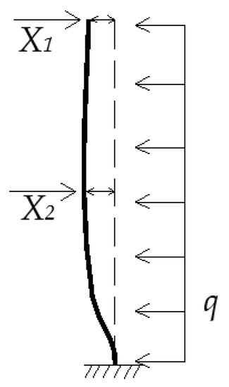
Figure 9.
Basic structure of force method under uniformly distributed load of wall column.
Because the deformation of the basic system is in the elastic stage, the internal forces of the basic system satisfy linear superposition, which means that the internal forces (axial force, shear force, and bending moment) can be expressed as the sum of the internal forces of the loads X1, X2, and q acting alone, as shown in Equation (11).
where , , and represent the axial force, the shear force, and the bending moment of the system, respectively.
, , , , , and represent the axial force, the shear force, and the bending moment on conditions of and , respectively.
, , and represent the axial force, the shear force, and the bending moment caused by load q.
It is assumed that the initial normal strain, the shear strain, and bending strain of the system are , respectively.
Then, the residual energy of the system under the state of static possible internal force is expressed as Equation (12).
where indicates the strain residual energy of the system under the possible internal force state, which is related to the internal force, expressed as Equation (13).
indicates the residual energy of the support displacement and is the negative value of the sum of the virtual work of the corresponding support reactions on the support seat, expressed as Equation (14).
where and represent the virtual work by the support reaction.
Bring Formula (11) into Formula (13), and the residual energy of the statically indeterminate structure is shown as Equation (15).
where
- indicates the virtual displacement of the i-th support of the system when is acting alone ().
- indicates the virtual displacement of the j-th support of the system when is acting alone (; or ).
- indicates the displacement of the i-th support under the load ().
- indicates the displacement of the i-th support during initial deformation ().
The fixed end of the structure may experience displacement due to some poor fixation under the action of external forces. Assume that the horizontal bearing displacement, the vertical bearing displacement, and the angular displacement of the structure fixed end are , , and , respectively, and corresponding support reactions are , , and , respectively.
where , , , , , and represent support reactions in , , and directions on conditions and , respectively.
, , represent support reactions by the load q.
The residual energy of the support displacements can be expressed as Equation (17).
where
equals the displacement of , , and in the direction .
The residual energy of the structure is shown as Equation (18).
Apply the residual energy stationary condition of Equation (19).
We can obtain Equation (20).
Equation (21) can be concluded by the reciprocal theorem between the reaction and displacement.
The deformation of the structure under the action of its weight is minimal and negligible, so it can be assumed that the system has no initial strain, that is, the initial normal strain, shear strain, and bending strain are all zero, shown as Equation (22).
Then .
Then we can obtain . Then Equation (20) can be simplified as Equation (23).
When the bending deformation is the main form of the wall column, we can ignore the influence of axial force and shear force, and conclude Equations (24) and (25).
where , , and are the elastic modulus, the section moment of inertia, and the calculated length of the wall column, respectively.
Let , , and .
Then, the rigidity k can be obtained, shown as Equation (26).
Substituting Equation (26) into Equation (23), we obtain the solutions of and , respectively, shown as Equations (27) and (28).
The bending moment at the bottom of the wall column is obtained as Equations (29) and (30):
where and are bending moments at the wall column bottom for basic structure under the unit forces on points X1 and X2, respectively. is the bending moment under the action of .
X1 and X2 are brought into Formula (29), and the analytical solution of the bending moment at the wall column bottom under uniformly distributed load can be obtained, as shown in Equation (31).
where , , and under the action of triangular load Q can be obtained in the same way, shown as Equations (32) and (33), respectively.
Formulas (32) and (33) are brought into Formula (23), and the reaction forces at the top and middle elastic bearings on the wall column are obtained under triangular load Q, respectively, shown as Equations (34) and (35).
X1 and X2 are brought into Formula (29), and the analytical solution of the bending moment at the wall column bottom under triangular load Q can be obtained, as shown in Equation (36).
Let
Then, under the combined action of uniformly distributed load and triangular load, the analytical solution of the bending moment at the wall column bottom is obtained by linear superposition of bending moments, as shown in Equation (38).
where
- is the column–beam stiffness ratio, as shown in Equation (26).
- is the ratio of triangularly distributed load and uniformly distributed load , indicates the gradient change degree of the distributed load.
- is the calculated length of the wall column.
3. Simulations for the Model Verification
3.1. Basic Parameters of the Model
Taking a newly built metro station as an example, a reserved large-size opening with a cross section of 5 m × 28 m is set up on the roof of the metro station. The cross-section size of the wall column is 600 mm × 1800 mm, the distance between two adjacent wall columns is 3 m, and the strength grade of concrete used for the columns is C50. In addition, the cross-section size of the upper and lower frame beams is 800 mm × 1850 mm, and the thickness of the side wall is 600 mm with the C35 grade of concrete. The thickness of the earth covering above the roof is 1.5 m. The coefficient of active earth pressure is supposed to be 0.38, the groundwater is located below the bottom board, the ground vehicle load is supposed to be 20 kPa, the unit weight of the earth is 20 kN/m3, and other parameters are shown in Figure 10 and Figure 11.
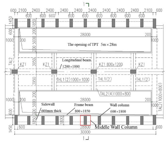
Figure 10.
Plan of the metro station with a reserved large-size opening (unit: mm).
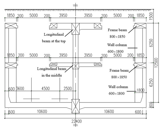
Figure 11.
Section of the opening (unit: mm).
3.2. Two-Dimensional Model for Verification
The two-dimensional model is built by the finite element software Midas gen [29], in which the beam element is used to simulate frame beams and the wall columns [30], and fixed constraints are applied at the bottom of the wall column. The wall column model with the frame beam is shown in Figure 12a (both ends of the beam and the bottom of the wall column are fixed constraints, and trapezoidal distributed load is exerted). Figure 12b–d shows the wall column models with elastic supports at the top and middle and fixed constraints at the bottom of the wall column. The stiffness of elastic supports is calculated by Equation (27). Moreover, Figure 12b–d represents the trapezoidal distributed load, the uniformly distributed load, and the triangularly distributed load acting alone on the wall column, respectively. Figure 13a–d shows the calculation results of bending moments under the corresponding model, respectively.
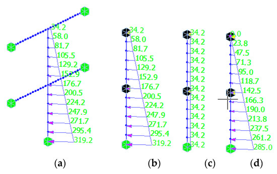
Figure 12.
Two-dimensional simplified simulation model of the wall column (unit: kN/m). (a) The wall column model with the frame beam and trapezoidal distributed load; (b) The wall column model with elastic supports and trapezoidal distributed load; (c) The wall column model with elastic supports and uniformly distributed load; (d) The wall column model with elastic supports and triangularly distributed load.
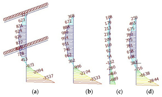
Figure 13.
Bending moment diagram of wall column under two-dimensional simulation model (unit: kN·m). (a) Bending moment diagram of the model of Figure 12a; (b) Bending moment diagram of the model of Figure 12b; (c) Bending moment diagram of the model of Figure 12c; (d) Bending moment diagram of the model of Figure 12d.
Based on the analytical solution of Equation (38), control bending moments at the bottom of the column and some significant parameters under various working conditions are obtained and shown in Table 1. In addition, soil pressure within the 3 m range in the horizontal direction is taken into account and converted into line load on the wall column, as the distance in the horizontal direction between two adjacent wall columns is 3 m.

Table 1.
Calculation sheet of analytic solutions by theoretical analysis.
As displayed in Figure 13a,b, after the beams are simplified as elastic support, the control bending moment at the bottom of the column is almost the same by theoretical equations and two-dimensional simulation, which indicates that regarding beams as elastic supports is rational and feasible. Meanwhile, it also verifies the correctness of the stiffness of the support deduced in this paper. Combined with the results in Table 1 and Figure 13, we can see that the analytical solution of control bending moments at the bottom of the wall column is the same as the finite element software simulation results. Thus, it certifies the validity of the analytical solution of control bending moments at the bottom of the wall column deduced in this paper.
3.3. Three-Dimensional Model for Verification
The two-dimensional model’s calculation only considers the structure’s deformation in the stress plane, ignoring the out-of-plane deformation, finite stiffness constraints of boundaries, and the interaction of walls, beams, and wall columns. The impact of the above factors on the accuracy of the structural calculation needs to be further discussed. Therefore, the rationality and accuracy of the two-dimensional model will be verified through three-dimensional modeling calculations.
The three-dimensional global model is built by the finite element software Midas gen [31]. The beam element is used to simulate frame beams and wall columns, and the shell element simulates the wall in the model. The structure can deform both in and out of plane, and the interaction of walls, beams, and columns is simulated through common node coupling. The essential parameters of this model are the same as those in Section 2.1. In addition, the impact of envelopes on the main construction of the metro station is ignored. The overall deformation of the three-dimensional simulation and the bending moment of the wall column is shown in Figure 14 and Figure 15, respectively.
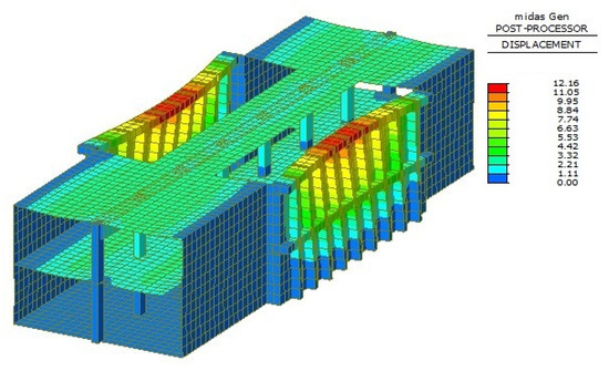
Figure 14.
Three-dimensional global deformation (unit: mm).
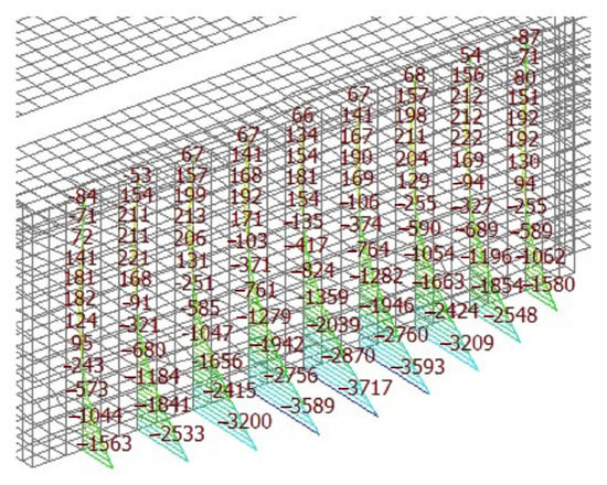
Figure 15.
The bending moment of the wall column under three-dimensional simulation model (unit: kN·m).
We can see from the overall deformation (Figure 14) that the deformation of the upper frame beam is greater than that of the middle frame beam. Meanwhile, the wall column’s deformation is the largest in the middle of the opening and decreases successively to both sides. The whole deformation characteristics of the side wall at the opening are similar to the plate: freedom at the top and consolidation at the other three sides. As illustrated in Figure 12, the maximum bending moment at the bottom of the central wall column (3717 kN·m) is the control bending moment of the wall column. The control bending moment of the wall column deduced by the analytical solution in this paper is 3533 kN·m. The error between the two methods is 4.95%, which agrees with the range of allowable errors in engineering. Thus, it verifies that the assumption of the analytical solution for the bending moment of the wall column is rational. Furthermore, it indicates that analytical solutions have better applicability and better predictive validity in determining cross-section sizes of beams and columns without three-dimensional analysis. Using this solution will significantly improve work efficiency in preliminary structural design engineering.
In addition, the main reason that the analytical solution is slightly less than the three-dimensional calculation result is that the limited rotational restriction of side walls at both ends of the frame beam and boundary columns cannot meet the hypothesis of absolute rigid connection. Therefore, the stiffness of the elastic support in the analytical model is slightly larger than that in the actual frame beam, and the corresponding bending moment at the bottom of the column is marginally smaller than that in reality.
The three-dimensional model that takes into account solid structures can simulate actual projects in a better way. The consistency between the calculation results of the two-dimensional model and the three-dimensional model further validates the basic assumptions of the two-dimensional calculation. The two-dimensional model can be used for efficient calculation during the preliminary structural selection analysis. Using three-dimensional models is more accurate when conducting quantitative structural analysis.
4. Discussions of Engineering Applicability of Theoretical Solutions
To fully demonstrate the engineering applicability of approximate analytical solutions derived in this paper, more simulations with different vital parameters such as distance between two adjacent wall columns, story height of the metro station, and the thickness of earth covering are completed. Moreover, the analytical result is compelling enough to predict the bending moment at the bottom of the wall column in possible practical engineering.
4.1. The Influence of the Story Height of the Metro Station
Based on parameters of the example in Section 3.1, only the story height of the station is changed. As height differences between two adjacent layers cannot exceed 2 m in subway station, height difference values of 2 m, 1 m, 0 m, −1 m, and −2 m are considered. In addition, the control-bending moments at the bottom of column under these height differences are obtained by three-dimensional simulation via software. Meanwhile, the analytical solution is still computed on the assumption of 0m height difference via Equation (38) (i.e. the upper and the lower story heights are equal). Bending moments at the bottom of the column under different conditions are shown in Figure 16. The comparison between simulation and analytical solution is shown in Table 2.
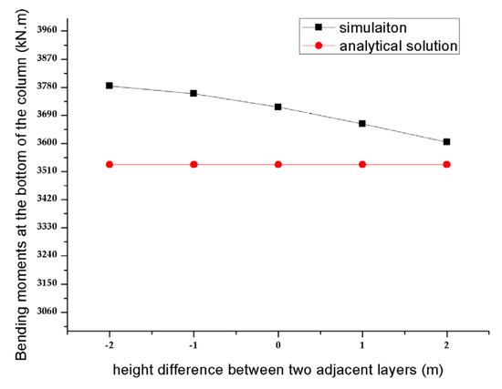
Figure 16.
Relation curve of the column bottom bending moment with different story heights of the metro station.
Table 2.
The comparison between simulation and analytical solution within different heights of two layers.
It can be seen from Figure 16 and Table 2 that the error between analytical solutions and the simulation results ranges from 2.0% to 6.6%, which indicates that the slight changes in the height difference of the metro station cannot play a decisive role in the control bending moment at the column bottom. In addition, it can be certified that the assumption of the same story height of the upper and lower layers of the metro station is rational in theoretical analysis.
4.2. The Influence of the Distance between Two Adjacent Wall Columns
Based on the parameters of the example in Section 3.1, the distance between two adjacent wall columns is adjusted to 2.5 m, 3 m, 3.5 m, 4 m, and 4.5 m, respectively. The relationships between the bending moment at the bottom of the column and the distance of two adjacent wall columns are calculated by three-dimensional Midas gen software, and analytical solutions are obtained via Equation (38), as shown in Figure 17.
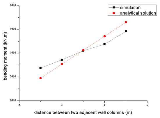
Figure 17.
Relation curve of the column bottom bending moment with the distance between the wall columns.
We can see in Figure 17 and Table 3 that analytical solutions are well coincident with the results obtained by software under the different distances between the wall columns, and the maximum error is less than 13%. Hence, it shows that the analytical solution of Equation (38) applies to various column spacing.
Table 3.
The comparison between simulation and analytical solution with different distances between two wall columns.
4.3. The Influence of the Thickness of Earth Covering
Different soil types affect the structure differently. In structural analysis, the impact of soil is mainly reflected by soil pressure. Different types of soil produce different soil pressure distributions. Still, the distribution rules of soil pressure have similar characteristics, which can be simplified as trapezoidal distributed loads or segmented trapezoidal distributed loads. Furthermore, the influence of segmented trapezoidal distributed loads on structural response can be considered the superposition of trapezoidal distributed loads in structural analysis.
This study focuses on analyzing control parameters for the location of TPT openings in complex underground spaces. The research object is a two-layer subway station with a buried depth of no more than 21 m. In the practical engineering of subway stations, the soil properties within this range are almost uniform. This article discusses the primary working conditions for the soil to be homogeneous and focus on the relationship between the opening position and the control bending moment under different thicknesses of earth covering trapezoidal distributed earth pressure.
Let us take parameters in Section 3.1 as an example, and only the values of thickness of the earth covering are considered as 1.5 m, 2 m, 3 m, 4 m, 5 m, and 6 m. The relationships between the bending moment at the bottom of the column and the thickness of the earth covering are gained by three-dimensional Midas gen software, and analytical solutions are obtained via Equation (38), as shown in Figure 18.
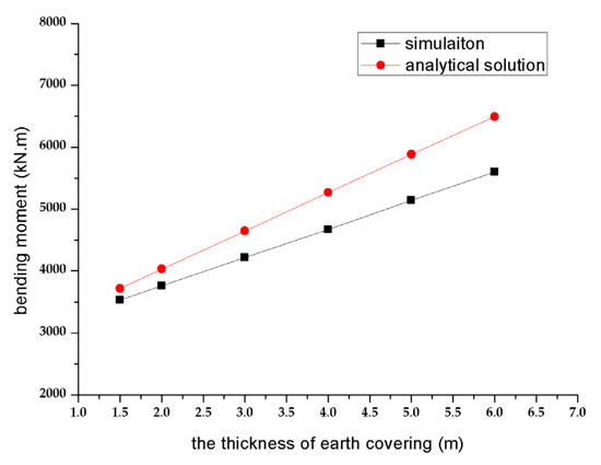
Figure 18.
Relation curve of the column bottom bending moment with the thickness of earth covering.
From Table 4, the error between analytical solutions and the simulation results ranges from 4.9% to 13.7% under the different thicknesses of the earth covering. The error increases with the thickness of the earth covering in the acceptable scope, and the analytical solution has the advantage of high goodness of fit and satisfactory effect.
Table 4.
The comparison between simulation and analytical solution within different thickness of earth covering.
In addition, the approximate analytical solutions deduced in this paper are very close to three-dimensional simulation results compared to the above key factors, such as the distance between wall columns, the story height of the metro station, and the thickness of the earth covering in the actual engineering. Equation (38) is engineering applicable and can be quickly and easily applied to most similar projects.
5. Discussions about the Control Parameter of the Complex Underground Structure System Design
As the floor height and overburden thickness of the station are fixed values after the determination of the functional requirements of the subway station and the external environment, parameters , , and are determined in Equation (38). Engineers can actively adjust the section sizes of the wall columns and the frame beams, that is, the stiffness ratio between the wall column and the frame beam , which can be named as the column–beam stiffness ratio. A correct and comprehensive understanding of the influence law of the parameter is essential to improve the personal initiative of engineers in engineering design. Now, we will try to discuss .
(1) Let us suppose that the column–beam stiffness ratio approaches infinity, which means that the cross section of the frame beam of the side wall is so tiny that the stiffness can be ignored compared with the column. Then, the limit of the analytical solution formula can be expressed as Equation (39) when approaches infinity.
If we let , that is, there is only uniform linear load applied, Equation (39) is simplified to Equation (40).
(2) On the contrary, if the opening is far away from the frame beam of the side wall, the cross section of the frame beam of the side wall is large enough to bear any deformation. The column–beam stiffness ratio decreases to infinitely small consequently, and Equation (38) can be expressed as Equation (41) by taking the limit .
Set , i.e., there are only uniform distributed linear loads applied, then Equation (40) can be simplified to Equation (42):
which agrees with the calculation of the hogging bending moment value at the root of the beam with the fixed support at one end, the hinged support at the other end, and the mid-span under the uniform distributed load. In addition, the correctness of the derivation in this paper is also verified from the perspective of the limit.
(3) Taking the parameters in Section 3.1 as an example, let and substitute different values into Equation (38). The relationship diagram between the column bottom bending moment of the wall column and the stiffness ratio between the wall column and the frame beam is obtained, as shown in Figure 19.
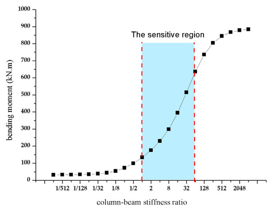
Figure 19.
Relation curve of the column bottom bending moment with column–beam stiffness ratio.
The wall column’s control bending moment increases remarkably with the increase of in the range of 1–64 from Figure 19, which means that there is a sensitive region of the column’s control bending moment to the column–beam stiffness ratio , and the change of the bending moment is not noticeable out of this region. Therefore, it is beneficial to reduce the concentration of the bending moment at the bottom of the wall column by taking the Track Panel Tunnel (TPT) openings a little closer to the middle longitudinal beam under the condition of meeting the functional requirements. However, the mechanical performance of the structure cannot be remarkably improved if the opening of the track panel well is too close to the middle longitudinal beam blindly, and this action will make the track panel inconvenient to be lifted. The determination of the reasonable column–beam stiffness ratio in the sensitive region is critical for structure designers to create a balance between the convenience and the mechanical performance of the structure.
Taking the metro station in Section 3.1 as an example, when the distance between the edge of the opening and the outside wall of the metro station is 3 m, the column–beam stiffness ratio is 1.92. The corresponding bending moment at the bottom of the column is 131.3 kN·m, with 42.8% fall compared with the original design distance of 1.85 m (α = 8.2, M = 229.5 kN·m). It is observed that a clear understanding of the relationship between the control bending moment of the wall column and the position of openings is essential for rational structure design, which is vital to improve the mechanical performance of the structure and save on the project cost for engineering.
(4) Because the story height of the station is 5.5~7 m, determined by the subway station’s functional requirements, the opening’s size is 27~30 m because of the standard length of the rail, the length-to-height ratio of the side wall in the opening range is generally greater than 2. Therefore, the mechanical characteristic of a double-story station’s side wall in the middle with an opening is similar to the one-way slab. The simplified model in the paper can be established and in good agreement with the simulation. Whether this implicit condition is satisfied affects the accuracy of the analytic solution directly and should be paid attention to in design.
(5) Variability of soil properties is a major source of uncertainty in assessing the seismic response of geotechnical systems [19], which makes the dynamic characteristics of the system more complex and needs to be analyzed in the future. This paper uses the load-structure method to consider the soil impact, which is appropriate in the static calculation results of this paper. The stratum-structure rule is more suitable for the numerical calculation of dynamic analysis, which treats the underground structure and soil as a whole under the unified stress and deformation and calculates the deformation of the underground structure and surrounding soil based on continuum mechanics. In dynamic analysis, the range of the soil is often taken as the calculation area 5 times the size of the underground structure if the fixed boundary is used, which can eliminate the impact of boundary effects. Moreover, the research results of Zhang Zhiying et al. show that the soil–structure interaction system exhibits significant classical damping system characteristics under small magnitude loads, which means that the system can be solved by classical dynamic analysis methods such as the mode superposition method [32].
6. Conclusions
The design of the reserved large-size openings is a crucial point in complex underground space structure design, because this opening leads to its surroundings being the weakest part of the structure. The convenience, safety, and economy of the station with large-openings design cannot be considered comprehensively because of limited research about the relationship between the control bending moment at the bottom of the wall column and the position of the openings.
In this paper, the simplified calculation model of the control bending moment of the wall column under rational assumptions is abstracted, and an approximate analytical solution of the control bending moment of the wall column under soil and water pressure loadings is deduced. Then, the correctness of the formula is certified by two-dimensional finite element simulation. The three-dimensional simulation proves the assumptions’ rationality and the engineering applicability of the analytical solution. Meanwhile, the sensitive region of the control bending moment to the column–beam stiffness ratio is found through the analytical solution, which can be the critical point in determining the column–beam stiffness ratio reasonably while meeting the requirements of the actual design. It is useful for designers to determine the reasonable column–beam stiffness ratio to provide the basis for structural design optimization with cost savings in the preliminary design stage.
In addition, it is worth noting that basic assumptions and corresponding analytical solutions are obtained on the basis that the length-to-height ratio of the side is engineering applicable wall in the opening range should be generally greater than 2.
Author Contributions
Conceptualization, H.L. and Y.L.; methodology, H.L.; software, Y.L.; validation, Y.L.; formal analysis, Y.L. and H.L.; resources, H.L.; data curation, H.L. All authors have read and agreed to the published version of the manuscript.
Funding
This research was funded by the Scientific Research Program Funded by the Education Department of Shaanxi Provincial Government, grant number 20JK0741. Natural Science Basic Research Plan in Shaanxi Province of China, grant number 2021JQ-891. And the National Natural Science Foundation of China, grant numbers 51879212 and 41630639.
Institutional Review Board Statement
Not applicable.
Informed Consent Statement
Not applicable.
Data Availability Statement
All data are available in the paper.
Acknowledgments
This work was supported in part by the Youth Innovation Team of Shaanxi Universities. We would like to thank Xiaohua Liu for the help of the software, validation, and formal analysis.
Conflicts of Interest
The authors declare no conflict of interest. The funders had no role in the design of the study; in the collection, analyses, or interpretation of data; in the writing of the manuscript, or in the decision to publish the results.
References
- Shen, S.L.; Lin, S.S.; Zhou, A. A cloud model-based approach for risk analysis of excavation system. Reliab. Eng. Syst. Saf. 2023, 231, 108984. [Google Scholar] [CrossRef]
- Zheng, Q.; Shen, S.L.; Zhou, A.; Lyu, H.M. Inundation risk assessment based on G-DEMATEL-AHP and its application to Zhengzhou flooding disaster. Sustain. Cities Soc. 2022, 86, 104138. [Google Scholar] [CrossRef]
- Fu, Y.P.; Liao, H.J.; Chai, X.Q.; Li, Y.; Lv, L.L. A Hysteretic Model Considering Contact Angle Hysteresis for Fitting Soil-Water Characteristic Curves. Water Resour. Res. 2019, 57, eWR026889. [Google Scholar] [CrossRef]
- Shen, S.L.; Zhang, N.; Zhou, A.; Yin, Z.Y. Enhancement of neural networks with an alternative activation function tanhLU. Expert Syst. Appl. 2022, 199, 117181. [Google Scholar] [CrossRef]
- He, Y.-Q.; Wang, S.; Liao, H.-J.; Wu, W. A hypoplastic constitutive model for structured soils. Comput. Geotech. 2022, 151, 104935. [Google Scholar] [CrossRef]
- Yan, T.; Shen, S.L.; Zhou, A.; Chen, X.S. Prediction of geological characteristics from shield operational parameters using integrating grid search and K-fold cross validation into stacking classification algorithm. J. Rock Mech. Geotech. Eng. 2022, 14, 1292–1303. [Google Scholar] [CrossRef]
- Luo, Z. Design of Track Panel Shaft in Metro Tunneling Interval. Chin. J. Undergr. Space Eng. 2009, 5, 152–157. [Google Scholar]
- Huo, H.; Bobet, A.; Fernández, G.; Ramirez, J. Load transfer mechanisms between underground structure and surrounding ground: Evaluation of the failure of the Daikai station. J. Geotech. Geoenvironmental Eng. 2005, 131, 1522–1533. [Google Scholar] [CrossRef]
- Fuentes, R. Internal forces of underground structures from observed displacements. Tunn. Undergr. Space Technol. 2015, 49, 50–66. [Google Scholar] [CrossRef]
- Chen, Z.-Y.; Liu, Z.-Q. Effects of central column aspect ratio on seismic performances of subway station structures. Adv. Struct. Eng. 2017, 1, 14–29. [Google Scholar] [CrossRef]
- Xue, J.; Wang, Y.; Huang, X.; Dai, W.; Lou, G. Mechanical Performance of Subway Atation with Large Size of Holes in the Floor. J. Guangxi Univ. 2018, 43, 1–7. [Google Scholar] [CrossRef]
- Ministry of Railways of the People’s Republic of China. Code for Design on Retaining Structures of Railway Subgrade: TB 10025—2006; China Railway Publishing House: Beijing, China, 2009. (In Chinese) [Google Scholar]
- Iida, H.; Hiroto, T.; Yoshida, N.; Iwafuji, M. Damage to Daikai subway station. Soils Found. 1996, 36, 283–300. [Google Scholar] [CrossRef] [PubMed]
- Zhao, D. The Analysis and Discussion about Simplified Plane-strain Model for the Structure with a Large-size Hole. Spec. Struct. 2010, 27, 18–21. [Google Scholar] [CrossRef]
- Mikkola, M.J. Complementary energy theorem in geometrically non-linear structural problems. Int. J. Non-Linear Mech. 1989, 24, 499–508. [Google Scholar] [CrossRef]
- Fu, B.-L. Variational Principles for Dual and Triple Mixed Variables of Linear Elasticity with Finite Displacements and the Application. Appl. Math. Mech. 2017, 38, 1251–1268. [Google Scholar] [CrossRef]
- Goodman, R.F.; Tayor, R.L.; Brekke, T.L. A model for the mechanics of jointed rock. J. Soil Mech. Found. Div. 1968, 94, 637–660. [Google Scholar] [CrossRef]
- Wang, M.C.; Shao, M. Basic Principles and Numerical Methods of Finite Element Method; Tsinghua University Press: Beijing, China, 1999. (In Chinese) [Google Scholar]
- Das, B.; Saha, R.; Haldar, S. Probabilistic Seismic Design of Soil-Pile Raft-Superstructure System. Geotechnical Special Publication. In IFCEE; American Society of Civil Engineers: Reston, VI, USA, 2015. [Google Scholar] [CrossRef]
- Lu, F. Research on Stratum Spring Parameters and Stratum Boundary in Dynamic Calculation of Underground Structure; Zhejiang University: Hangzhou, China, 2020. [Google Scholar] [CrossRef]
- Fu, B.-L. Variational Principle and Application of the Elastic Mechanics Mixed Variables. National Defence Industry Press: Beijing, China, 2010. (In Chinese) [Google Scholar]
- Wang, L.; Lu, Z.-R.; Liu, Z.-Q. Complementary energy principle for elastodynamics: Free of volumetric locking. Int. J. Solids Struct. 2017, 120, 103–114. [Google Scholar] [CrossRef]
- Chen, Y.J. Bending of thick rectangular plates with different boundaries under concentrated load. Adv. Mater. Res. 2011, 163–167, 1440–1444. [Google Scholar] [CrossRef]
- Chen, Y.-J.; Li, Z.-H.; Fu, B.-L. Apply the principles of complementary energy with mixed variables to solve the bending of the rectangular plate with simply supported on four sides under different loads. Chin. J. Comput. Mech. 2015, 32, 287–292. [Google Scholar]
- Chen, Y.J.; Wu, J.Y.; Wang, C.; Lei, Z.; Song, J.W. Seismic Performance Upgrading for Underground Structures by Introducing Shear Panel Dampers. Adv. Struct. Eng. 2014, 9, 1343–1357. [Google Scholar] [CrossRef]
- Jadhav, P.; Singh, M.; Prashant, A. Permanent displacement based seismic design chart for cantilever retaining walls. In Proceedings of the GeoShanghai 2018 International Conference: Advances in Soil Dynamics and Foundation Engineering, Shanghai, China, 27–30 May 2018; Springer: Berlin/Heidelberg, Germany, 2018; pp. 543–550. [Google Scholar] [CrossRef]
- Jia, J.W.; Peng., F.L. Characteristics of earth pressure and soil displacement surrounding the deep underground structures. Tunn. Undergr. Constr. 2014, 122, 134–142. [Google Scholar] [CrossRef]
- Kim, Y.W.; Kim, N.I.; Lee, J. Damage identification of truss structures based on force method and free vibration analysis. Adv. Struct. Eng. 2016, 1, 3–13. [Google Scholar] [CrossRef]
- Abdullah, M.; Kulkarni, P. Behaviour of Multi-Storey RC Building Under Seismic Load Using Pushover Analysis. IOP Conf. Ser. Mater. Sci. Eng. 2021, 1197, 012012. [Google Scholar] [CrossRef]
- Qin, X.-J.; Zhang, X.-A.; Liu, X.-A.; Wang, X.-B. Investigation of Wind Vibration of the Additional Columns Stiffness Ratio on the Mega-sub Controlled Structure. Earthq. Resist. Eng. Retrofit. 2009, 31, 26–31. [Google Scholar] [CrossRef]
- Zhu, C.; Zhang, W. Structural Mechanics, 3rd ed.; Higher Education Press: Beijing, China, 2016. (In Chinese) [Google Scholar]
- Zhang, Z.; Li, Y.; Yin, Y.; Han, Z. Study on Identification Method of Motion States at Interface for Soil-Structure Interaction Damping System. Appl. Sci. 2022, 12, 1729. [Google Scholar] [CrossRef]


Disclaimer/Publisher’s Note: The statements, opinions and data contained in all publications are solely those of the individual author(s) and contributor(s) and not of MDPI and/or the editor(s). MDPI and/or the editor(s) disclaim responsibility for any injury to people or property resulting from any ideas, methods, instructions or products referred to in the content. |
© 2023 by the authors. Licensee MDPI, Basel, Switzerland. This article is an open access article distributed under the terms and conditions of the Creative Commons Attribution (CC BY) license (https://creativecommons.org/licenses/by/4.0/).