Abstract
Chromonic liquid crystals have recently received a lot of attention due to their spontaneous self-assembly in supramolecular columnar structures that, depending on their concentration in water, align to form a nematic liquid crystalline phase. The chirality may be induced in chromonics by adding chiral moieties to the nematic phase or enhanced by confining them in curved geometrical constraints. This review summarizes the recent research developments on chiral chromonic liquid crystals confined in spherical geometry, relating the results to what was observed for thermotropic liquid crystals in the same conditions. The review focuses on the studies carried out on commercially available nematic chromonics, investigating the effects on their topologies in different anchoring conditions and different chiral dopants and suggesting an application in the sensor field.
1. Introduction
This review is focused on a peculiar state of matter: chromonic liquid crystals. These materials are columnar liquid crystals that self-assemble in water. One typical example is DNA. There are several reasons to study them. First of all, the molecules are biocompatible and their mesophases could be applied in sensor and food safety fields. However, the self-aggregation mechanism is not fully understood and the behavior of these compounds when confined among two glasses is unpredictable. Furthermore, apart from native cholesteric chromonics, the chirality can be induced in the nematic compounds doping them with a suitable chiral amino acid. However, the connection between the chirality at the molecular scale and the macroscopic chiral structure of the liquid crystalline phases is not yet understood [1].
In recent years, researchers demonstrated that chromonics assume a spontaneous torque when they are confined to cylindrical or spherical geometries. Most of the studies focused on tactoids or cylindrical capillaries [2,3,4,5].
Tactoids are spindle-like droplets in which an ordered nematic phase appears when cooling the isotropic phase. The nematic phase coexists with the isotropic phase in a broad range of concentrations and temperatures. The director configuration and the shape of the tactoids are determined by the balance between the elastic volume and the surface energies [2]. Since chromonics have a small twist elastic constant with respect to the splay and bend constants, the nematic director field is twisted. Since the system is not natively chiral, the number of tactoids with the left and right twist is approximately the same. In 2015, Peng and Lavrentovich [5] demonstrated that a small amount of R or S chiral molecules can amplify the chirality, turning chiral tactoids into either right- or left-twisted structures. The chirality amplification is demonstrated by an increased optical activity of these structures.
In the last twenty years, there has been an increasing interest in thermotropic chiral liquid crystals confined in curved geometries. Several investigations have been carried out allowing researchers to theoretically predict and experimentally observe a plethora of topological configurations [6,7,8,9].
In particular, the optical properties of chiral nematic microspheres have been exploited in several application fields. For example, chiral microdroplets can be used as tunable microlasers. Microdroplets containing a dye-doped cholesteric liquid crystal exhibit omnidirectional lasing from the center of the drop when they are optically pumped, with the lasing wavelength that depends on the pitch of the cholesteric. [10,11].
Additionally, it is possible to create band edge lasers using dye-doped chiral nematic liquid crystals emulsified within a polymer matrix and deposited onto a rigid and flexible substrate [12] or encapsulated in free-standing films [13].
CLC droplets can be used not only for laser application but also for sensing. Lee et al. demonstrated their use as biosensors [14]. Petriashvili et al. investigated the possibility of using an emulsion of dye-doped chiral liquid crystals microdroplets dispersed in a glycerol matrix as a sensor for the presence of nitric acid molecules [15].
Finally, in 2016, Geng et al. proposed an anti-counterfeiting system based on the optical properties of a cholesteric liquid crystal emulsion [16]. The different chiral microspheres and microshells in random positions when illuminated by visible light, owing to the cross talk and selective reflection phenomena, exhibited a peculiar optical pattern that was irreproducible and could not be tampered with.
In this perspective, the possibility of confining or encapsulating the chromonics materials in the microspheres represents an opportunity for the creation of biocompatible devices to be exploited, expanding the aforementioned applications into the biological and pharmaceutical fields.
This type of confinement has been achieved in chromonics using tactoids encapsulated in a polymeric matrix.
In 2016, MacLachlan and co-workers presented a successful attempt to encapsulate chromonic liquid crystals [17]. The polymerization of polyacrylamide (PAAm) hydrogels in inverse emulsions was used to capture the chiral nematic structure of the cellulose nanocrystals in the microspheres. Chiral tactoids formed in the water droplets of an inverse emulsion system in the presence of the PAAm precursors, and the photopolymerization of PAAm solidified these droplets with the encapsulated chiral nematic tactoids.
Even if these structures are extremely interesting from a fundamental point of view, they are not easily tunable in terms of the optical properties and are not attractive for practical applications with respect to what can be obtained using emulsification or microfluidics technologies.
This review collects the latest experimental results present in the literature on the optical textures observed in the chiral chromonic microspheres prepared using mixtures of chromonics and chiral dopants for thermotropic liquid crystals. The review starts from a detailed description of chromonics, provides an overview of the theoretical models that describe the topological defects that can arise in thermotropic liquid crystals confined in the microspheres with different anchoring conditions and reports the experimental validation of these models on chromonics in their nematic and chiral-induced mesophases. The possibility to vary the anchoring conditions at the surface using different oils provides an opportunity to observe different interesting features and it is a step toward the comprehension of the self-assembling mechanism of these fascinating compounds. Finally, we provide a brief description of the possible applications.
2. Brief Description of Chromonics
Chromonics are a subset of lyotropic liquid crystals. Their name is derived from the Greek word “chroma” meaning color, indicating that many chromonics are colored [18].
They usually consist of a rigid hydrophobic discotic core that is composed of hydrophobic aromatic rings with hydrophilic groups [19]. Some examples of chromonic LCs include drugs, such as disodium chromoglycate, that are often used in anti-asthmatic treatments; dyes, such as Sunset Yellow, that are used in the food industry; DNA nucleotides such as guanine derivatives; DNA itself and cellulose. The interest in chromonic materials relies on the fact that their molecules are able to self-assemble.
The driving force for molecular aggregation appears to be an enthalpically driven face-to-face adhesion between the aromatic rings [20]. Not only are the π–π interactions between the aromatic complexes involved in the aggregation but the flexibility and nature of the chains connecting the complexes, the nature of the other functional groups around the complexes and the electrostatic and dipolar interactions between the complexes also define the organization between the molecules [21]. These interactions (electrostatic, excluded volume, hydrophobic) constrain the aromatic complexes to arrange themselves in very specific orientations relative to each other [22]. Then, during stacking, chromonic molecules can position themselves on each other, so the stack is perpendicular to the flat chromonic molecule, or they can undergo displacement, so the stack is angled. In other cases, the arrangement is even more complex.
However, for chromonic self-assemblies, there is neither an optimum aggregation size nor a critical temperature for the onset of the aggregation. Additionally, the energy of the assembly is high [20,21,22]; hence, there are significant energy barriers for the dynamic dissociation and re-association of these molecules.
Due to the presence of these elongated aggregates, chromonics are able to form two mesophases (Figure 1): the nematic (N) phase at low concentrations, consisting of a nematic matrix of columns, and the M phase at higher concentrations, in which the columns pack into a regular two-dimensional hexagonal lattice.
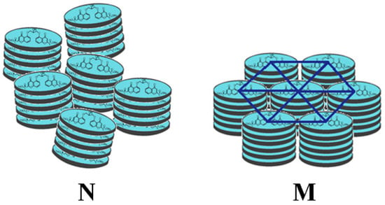
Figure 1.
Scheme of the N (left) and M phases (right) for a chromonic liquid crystal.
The best way to illustrate the mesophase existence intervals of a chromonic material in water is to consider its phase diagram, which identifies them as a function of their temperature and concentration [23,24].
Figure 2a shows the molecular structure of disodium chromoglycate (DSCG), whose phase diagram in a deionized water solution is reported Figure 2b. DSCG is the disodium salt of dibasic acid: 1,3-bis (2-carboxychromon-5-yloxy)-2-hydroxypropane [25]. Its crystals are an interstitial solid solution, with water as the interstitial component. In the solution, the unit cell expands to accommodate up to approx. nine water molecules before collapsing to form liquid crystalline hydrates. The DSCG crystals are unique in their degree of reversible water absorption without causing a lattice collapse.
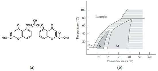
Figure 2.
(a) DSCG molecular structure and (b) its phase diagram. Reprinted with permission from ref. [19]. Copyright 2011, Taylor & Francis.
For the DSCG concentrations between 10 and 15 wt%, the nematic phase appears at room temperature. For the concentrations of 20 wt% or more, a columnar phase appears. The phase diagram contains large intervals in which the two phases coexist. At room temperature, the N and M phases coexist in the range of 15 to 20 wt%.
Another well studied chromonic is Sunset Yellow (SSY), Figure 3a shows its molecular formula. SSY can exist in two tautomeric forms [26]: an NH hydrazone form, where the hydrogen resides on the distant nitrogen of the azo bond, and an OH azo-tautomer form, where the hydroxide proton resides on the oxygen in ortho rather than the azo bond. Edwards et al. [27] showed that the NH hydrazonic form prevails. The azo form can produce cis-trans isomers. This change in the isomers occurs when the molecule interacts with light in the 480–500 nm wavelength range. As shown in the phase diagram in Figure 3b, the N phase appears at a concentration of approx. 30–40% by weight, while the hexagonal phase appears at approx. 40–45% by weight.
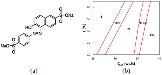
Figure 3.
(a) SSY molecular structure and (b) its phase diagram. Reprinted from [28].
For the largely studied thermotropic liquid crystals, to describe the phenomena involving them on a larger-than-molecular scale, it is more convenient to consider them as continuous media, defining the director and considering the splay, twist and bend deformations to describe the elastic deformation of the material. If the liquid crystal is confined, then the anchoring energy that is related to the interaction of the molecules at the interface surface will need to be considered.
It is well known that the elastic energy E associated with a liquid crystal confined between two surfaces [29] can be divided into two components: one component that depends on the elastic deformations of the liquid crystal in the volume (FV) and one that depends on the interactions at the interface (FS).
The elastic deformations were studied for both DSCG and SSY and the elastic constants were measured [30]. For DSCG, at a concentration range (12.5–18 wt%), the twist constant (K22) was more than 10 times smaller than the splay (K11) and bend (K33) constants. In particular, K11, K22 and K33 were 10.2, 0.7 and 24.9 pN, respectively. For SSY, similarly to DSCG, the twist constant was much smaller than the splay and bend constants, while K11 and K33 were comparable to each other. In particular, K11, K22 and K33 were 4.3, 0.7 and 6.1 pN, respectively [30,31].
3. Theoretical Modeling of Defects in Thermotropic Microspheres
Droplets are the simplest and most symmetric confining container for liquid crystals. When a liquid crystalline volume is confined to a spherical geometry, the anchoring conditions at the interface impose topological constraints on the director field that inevitably causes the topological defects to form [32]. These defects are interesting not only from a scientific point of view but, as mentioned in the introduction, they can also be useful for technological applications [33,34].
The confinement of thermotropic liquid crystals in the microspheres is easily obtained by dispersing them in an immiscible fluid (for example, water-based polymers or glycerol). Due to their immiscibility, an interface is formed between the liquid crystal and the surrounding fluid. Since the interface formation costs energy, the liquid crystal droplets tend to minimize the surface free energy by assuming a perfectly spherical shape. Inside the microsphere, the nematic director vector field depends on three factors: the anchoring of the liquid crystal at the interface, the elastic properties of the liquid crystal and the size of the sphere.
In a liquid crystal microsphere, the balance between the volume and surface energy is complex. The volume elastic energy FV scales linearly with the radius of the drop R, whereas the surface energy FS is proportional to WR2 where W is the anchoring energy. From this, it is evident that as the radius R of the liquid crystalline droplet increases, the interface contribution predominates over the volume contribution and, therefore, the influence of the topological constraints imposed by the interface vanishes for the small droplet sizes.
Comparing the two energy contributions, it is possible to define a critical radius as the ratio of the elastic energy to the anchoring energy K/W [32]. For the droplets of radius smaller than the critical radius, it will be energetically favorable to change the anchoring at the surface [35] and, thus, relax the elastic deformation leading to a uniform orientation of the director (Figure 4). This happens for the droplets with a radius in the order of a micron.
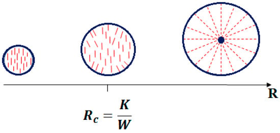
Figure 4.
Schematization of a nematic liquid crystal drop with homeotropic surface anchoring conditions and varying size.
If the droplets radius is larger than the critical value, topological defects will appear. In an article from 2011, T. Lopez Leon and A. Fernandez-Nieves exhaustively collected the phenomenology of the observed textures identifying them as a function of their elastic properties and anchoring conditions [36].
Among them, for the planar anchoring with K11 < K33, a bipolar configuration is typically observed (Figure 5a). In this configuration there are two defects, called boojums, at the poles. The bipolar configuration shows splay distortions near each defect and bend distortions in the rest of the drop.
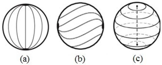
Figure 5.
Director’s field schematization for a spherical droplet in planar anchoring conditions: (a) bipolar configuration, (b) twisted bipolar configuration (c) defect line along the diameter of the drop. Reprinted with permission from ref. [36]. Copyright 2011, Springer Nature.
Adding a twist to this configuration, a twisted bipolar configuration is obtained (Figure 5b). The resulting structure still maintains the two boojums at the poles, but the surface director field is at an angle relative to the axis that connects the two point defects. The bipolar twisted configuration forms when K11 ≥ K22 + 0.431K33. Instead, when K11 < K22 + 0.431K33 and K11 > K33 and K11 < K33, the director organizes itself into a series of concentric circles, forming a structure that has a defect line along the diameter of the drop (Figure 5c). This structure is unstable.
For homeotropic anchoring, the frequently observed configuration for the nematics, which favors a splay to bend distortion, is the radial drop (Figure 6a). A pure splay is obtained with a localized defect, called a hedgehog, in the center of the drop. A variant of this structure results from the presence of twist distortions to form a twisted radial drop (Figure 6b).
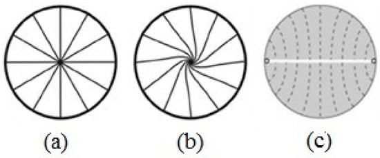
Figure 6.
Director’s field schematization for a spherical droplet in homeotropic anchoring conditions: (a) radial drop, (b) twisted radial drop (c) ring defect located on the surface of the drop along one of the two equatorial lines. Reprinted with permission from ref. [36]. Copyright 2011, Springer Nature.
For nematics that favor a bend to splay distortion, the director is organized around a ring defect located on the surface of the drop along one of the two equatorial lines (Figure 6c). In this case, the director has a cylindrical symmetry, and there is a defect line perpendicular to the director’s preferred orientation (on the drop’s equator).
For the cholesteric phases, more complex configurations are formed. As it is well known, in a cholesteric liquid crystal, the director describes a helix in the volume and, due to the cylindrical symmetry of this phase, the whole structure is periodic after a half rotation. Two parameters control the configuration of the director within a cholesteric drop: the anchoring conditions at the interface and the twisting power qR, where R is the radius of the drop and q is the inverse of half the pitch.
For planar anchoring and a low twisting power (qR < 1), the resulting drop configuration is a twisted bipolar (Figure 7a). For planar anchoring and a high twisting power (qR > 1), the most frequently observed configuration is the Frank–Pryce structure, which consists of a central hedgehog with a defect line along the radius (Figure 7e). This line can be explained considering the liquid crystal as a set of nematic planes. The line is the result of the concentric stacking of these nematic layers inside the drop, with each layer slightly rotated with respect to the other. The defect line can be seen as a linear stacking of defect points in each cholesteric layer. By varying the droplet size with respect to the cholesteric pitch, the configuration of the drop progressively changes from a twisted bipolar to the Frank–Pryce structure (Figure 7b–d).
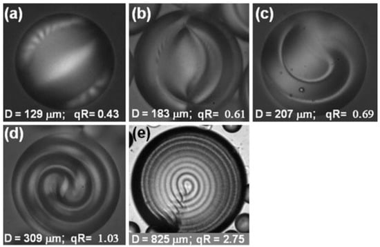
Figure 7.
Cholesteric liquid crystal droplets with planar anchoring conditions and different torque power, qR, ordered ascendingly (a–e). Reprinted with permission from ref. [36]. Copyright 2011, Springer Nature.
The case for the homeotropic alignment was studied in detail by Krakhalev and co-workers [37]. The authors reported on the orientational structures observed in cholesteric droplets as a function of the helicity parameter N0 = 2d/p (d is the droplet diameter). A sequence of structures were identified comparing the director configurations and topological defect-simulated textures with polarized light optical microscopy images [38,39].
When N0 = 1.1, the radial structure was observed, the point defect was located in the center of the drop and the director distribution was not twisted. In the drops where N0 > 1.1, the twisted radial structure was observed (Figure 8a).
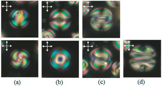
Figure 8.
Optical textures taken between the crossed polarizers (double arrows). The symmetry axis was oriented parallel (top row) and perpendicular (bottom row) to the viewing plane. (a) A 7.5 μm droplet (N0 = 2.7) with the twisted radial structure; (b) a 14 μm droplet (N0 = 5.1) with the toron-like structure; (c) a 15 μm droplet (N0 = 5.5) with the intermediate (L0) structure; (d) a 17 μm droplet (N0 = 6.2) with the layer-like (L) structure. The bipolar axis lies in the plane of the film and the polarizer is aligned perpendicularly to the bipolar axis. Reprinted with permission from ref. [37]. Copyright 2005, the Royal Society of Chemistry.
When 2.9 ≤ N0 ≤ 5.8, the toron-like structure is observed. This structure presents the formation of an equatorial circular defect line near the drop surface (Figure 8b). A further increase in the droplet diameter leads to a layer-like L structure with a bipolar distribution of helical axes and with a double twist defect line near the surface (Figure 8d). There is also another structure called the intermediate layer-like structure L0 that shows a number of twists and does not vary as a function of the drop size, having both a fixed geometry and a layered nature (Figure 8c). In some intervals, the different textures are observed simultaneously (Figure 9).
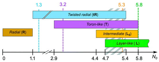
Figure 9.
Diagram of the observed textures at various droplet sizes as a function of the relative helicity parameter N0. Reprinted with permission from ref. [37]. Copyright 2005, the Royal Society of Chemistry.
4. Confinement of Nematic Chromonics and Native Chiral Chromonics in Microspheres
Compared to the thermotropic liquid crystals, the chromonic liquid crystal droplets are less studied because it is difficult to confine them in a matrix and prevent both coalescence and water evaporation.
In 2013, Joonwoo Jeong and his co-workers carried out detailed studies on the chromonic liquid crystal Sunset Yellow confined in the microspheres with planar anchoring conditions at the interface [40]. The microdroplets containing SSY in water in a percentage of 31% in weight were stabilized in a hexadecane matrix containing a non-ionic surfactant: sorbitan monooleate (Span 80). As mentioned above, the nematic director field in a typical bipolar configuration observed in a thermotropic nematic LC presents two boojums located at opposite poles of the drop. These are represented in Figure 10 by the black dots, while the yellow rods represent the director configuration. Instead, the authors observed a distorted chiral bipolar configuration in the chromonic nematic microspheres in which the director rotated in a helicoidal manner with the axis of the helix perpendicular to the boojums (Figure 10b).
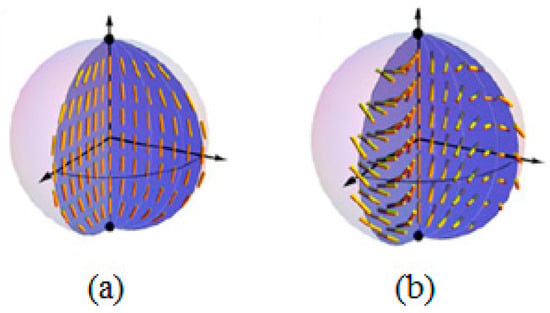
Figure 10.
Schematic diagrams of (a) the bipolar configuration and (b) the twisted bipolar configuration. Reprinted with permission from ref. [40]. Copyright 2014, the National Academy of Sciences.
As underlined, in chromonics, the twist elastic constant is an order of magnitude smaller than the bend and splay constants. This explain why, when they are confined in curved geometries, a large reflection symmetry breaking is observed, i.e., the strong splay and bend deformations of the director are relaxed trough the twist deformation.
Their findings are extremely interesting since Jeong et al. demonstrated that the confinement in a curved geometry highlights a spontaneous formation in the nematic phase of the chiral patterns from the achiral building blocks.
There are few examples in the literature of chiral chromonics that were confined in a spherical geometry. The most remarkable one is the work published by Yungfen Li and his co-workers in 2016 [41]. The authors presented an extensive investigation on cellulose nanocrystals (CNCs) confined in micrometric spheres. CNCs are stiff rod-like particles consisting of cellulose chain segments that present an almost perfect crystalline structure and have an average length of 183 nm and a diameter of 23 nm. CNCs are intrinsically chiral and form at the proper concentrations in a chiral liquid crystalline phase [42].
The confinement was obtained using an aqueous 7 wt% CNC suspension following a precise protocol, together with the exploitation of the microfluidic techniques. The immiscible matrix was a mixture of a fluorinated oil (F-oil) containing 1.0 wt% of a surfactant triblock copolymer perfluoropolyether and poly(ethylene oxide-co-propylene oxide).
The authors demonstrated that, in the presence of a strong planar anchoring, the textures obtained showed spherical layers arranged in a concentric manner with a defect at the center of the sphere and a radial disclination line. The textures were size dependent, in particular for the droplets with a radius in the range between 40 μm and 115 μm, a Frank–Pryce-like texture was obtained.
Interestingly, the core of the drop was in the isotropic phase, while the rest of the drop was in the chiral phase, showing a phase separation between the core and the rest of the droplet. The optical microscope image in polarized light (Figure 11) of a droplet exhibiting Frank–Pryce texture showed the characteristic structures of the cholesteric phase, a Maltese cross and a shell with alternating light and dark concentric rings corresponding to the surfaces at a constant refractive index. The concentric spherical packing of the cholesteric layers began at the interface between the microsphere and the immiscible matrix and gradually propagated towards the center of the drop. The center appeared black, highlighting the presence of an isotropic core. The image also showed the presence of a disclination, indicated by a white arrow, and an occasional dislocation, indicated by a red arrow.
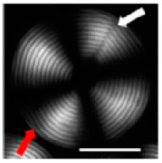
Figure 11.
Polarized light microscope image of a CNC cholesteric microdroplet. The scale bar is 50 mm. The white arrow indicates the defect running perpendicular to the cholesteric layers. The red arrow indicates an edge dislocation parallel to the cholesteric layers. Reprinted from [41].
This configuration can be explained by introducing another term in the Oseen–Frank theory of the elastic energy that it is usually neglected for thermotropic LCs: the saddle-splay term. The saddle-splay term, denoted K24, refers to a deformation of the director field such that n(r) is normal to a saddle surface [43,44]. Such surfaces have a negative Gaussian curvature, i.e., two principal curvatures of opposite signs and a saddle curve upwards along the crotch but downwards through the crotch. The corresponding energy density is a pure divergence term.
When considering strongly confined LC samples, such as droplets, the total free energy is the sum of three contributions: the volume, anchoring and saddle-splay. The latter is the only contribution that has a negative sign. A saddle-splay deformation of the boundary interface decreases the energy if K24 > 0. When the sample boundaries are flat, the contribution of f24 disappears totally. In contrast, on small microspheres with strongly curved boundaries that impose elastic distortions within the LC, this contribution can play an important role.
A very important difference between chromonic and thermotropic chiral liquid crystals is the size of the isotropic core, which is much larger in chromonics. To understand the mechanism that leads to the creation of such a large isotropic core in the CNC droplets, the balance between the elastic, condensation and surface energies must be considered. The free energy associated with the formation of an isotropic core with a radius ri, in a microsphere in which the radius is larger than the cholesteric helical pitch, is given by the following formula [41].
The first term is related to the distortion of the cholesteric layers, the second is related to the energy at the cholesteric–isotropic interface and the third is the difference in the free energy between the isotropic and cholesteric phases. Σchi is the tension at the interface between the chiral and isotropic phases and fi and fch are the free energy densities of the isotropic and chiral phases, respectively. The only term that favors the existence of an isotropic core is −8π (K11–K24) ri, for which the elastic energy is reduced when the curved chiral layers are replaced in the center of the drop with an isotropic spherical region. This implies that a fraction of the CNC is transferred from the core into the cholesteric shell. The fraction transferred in the volume is very small and no significant change in the measured pitch is observed in the shell. For the values typical of chromonic liquid crystals, Equation (3) predicts a radius ri in the order of 1μm, which is close to the experimentally measured value. This radius is two or three orders of magnitude larger than the one recorded for a thermotropic liquid crystal, usually between 2 nm and 50 nm [43,45].
5. Induced Chiral Chromonics in Microspheres
Apart from native chiral chromonics, the chirality can be induced in chromonics, adding a proper number of chiral molecules to the nematic mesophase. In a paper published in 2008 [46], T. Shirai et al. demonstrated the chirality induction in DSCG by doping it with the chiral additives L-carnitine, L-alanine, isosorbide, disodium L-tartrate dihydrate and trans-4-hydroxy-L-proline (trans-Hyp). Shirai et al. investigated the textures observed in planar confinement and noted that DSCG doped with trans-Hyp showed the shortest pitch with some colorful reflections when observed from an oblique direction.
Recent articles demonstrated that the chirality amplification in chromonics allows researchers to obtain a rich variety of topologies in a spherical confinement as those observed for thermotropic liquid crystals. These findings were extremely interesting since the liquid crystalline phase of chromonics that have an important water content showed the same optical textures as pure thermotropic liquid crystals.
To confine chromonics in the microspheres, the emulsification technique relies on the immiscibility of the water-based chromonic and an oily matrix. The choice of the matrix was a crucial point since it had the double task of preventing the movement of the microspheres reducing the coalescence phenomena and providing the correct anchoring conditions at the interface. The chirality induction in a spherical confinement was investigated for the model chromonics, DSCG and SSY doped with different chiral moieties, and few differences and similarities were highlighted.
5.1. Chiral Induction in DSCG
The chirality was successfully induced in DSCG using three different types of chiral amino acids, i.e., L-alanine, L-lysine and trans-Hyp (Figure 12) with different helical twisting powers [47]. The optical properties of the chiral chromonics were studied as a function of three different types of confining matrices.

Figure 12.
Molecular structure of (a) L-alanine, (b) L-lysine and (c) trans-4-hydroxy-L-proline.
It is known that paraffin induces a planar alignment at the interface. When L-alanine 10 wt% was dissolved in DSCG 13 wt%, the water solution and microspheres were produced, and interesting textures were observed. Concentric periodic rings were visible at the borders of the microsphere and did not cover the entire area (Figure 13a). The measured periodicity was 8.6 ± 0.5 μm. The main problem with the use of paraffin is that the chiral textures or textures connected to chirality induction are not always observable in the microspheres. Additionally, there are problems related to the coalescence and quick water evaporation.

Figure 13.
DSCG 13 wt% and L-alanine 10 wt% in (a) paraffin, (b) silicon oil and (c) PDMS.
The use of silicon oil (49.3 cSt, Sigma Aldrich, Merck KGaA, Darmstadt, Germany) did not help in preventing the coalescence and the concentric rings were less defined than in the previous case (Figure 13b). The periodicity of the rings was approx. 7.0 ± 0.5 μm. The best-defined optical configurations were obtained through the use of polydimethyl siloxane (PDMS). The microspheres exhibited a well-defined chiral texture with concentric circles. The Frank–Pryce texture, which propagates from the borders to the central core, was already observed for native chiral chromonics (Figure 13c). In addition, the presence of radial disclinations was clearly visible, resembling what was observed in the thermotropic liquid crystals. The possibility of obtaining this kind of texture in the chiral chromonic liquid crystal microspheres was not obvious, because it was a three-component system composed mainly of water, whose temporal stability was a delicate thermodynamical equilibrium. Nevertheless, the chiral texture was well-defined, and the pitch was homogeneous. For example, as shown in Figure 13c, the diameter of the microsphere was approx. 89 μm with a pitch of 10.7 ± 0.5 μm. Additionally, the use of PDMS as matrix was extremely efficient in preventing the coalescence and water evaporation.
Not all the chiral dopants were effective in inducing the chirality in DSCG. Figure 14a shows the typical texture observed in a microsphere containing DSCG 13 wt% and L-lysine 10 wt% in paraffin, while Figure 14b shows the texture of a microsphere containing DSCG 13 wt% with 26 wt% of trans-Hyp, whose value was very close to the solubility limit of this dopant.
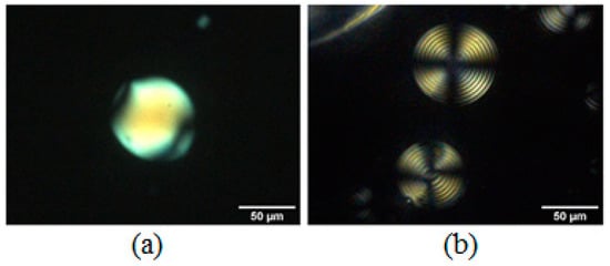
Figure 14.
DSCG 13 wt% doped with (a) L-lysine 10 wt% and (b) trans-Hyp 26 wt%.
L-lysine was less effective than trans-Hyp for inducing the chirality, with the latter allowing researchers to obtain a perfect Frank–Pryce texture showing a well-defined Maltese cross when observed between crossed polarizers. The average measured half-pitch was 1.65 ± 0.10 μm.
To understand the role of chiral amino acids and to investigate their position with respect to the supramolecular aggregates, X-ray diffraction measurements were carried out. The best performing amino acids—L-alanine and trans-Hyp—were used to prepare the chiral DSCG samples. The analysis was performed on chiral chromonic dried thin films deposited on thin solid films of PDMS. A slow drying procedure was carried out in controlled humidity and temperature conditions in order to allow the supramolecular aggregates to self-assemble in well-ordered phases.
As visible in Figure 15, the DSCG nematic phase, drying slowly, turned into the hexagonal phase that was observed at a small angle. When L-alanine was added, it favored a pair molecule interaction (supramolecular diffraction peaks visible in the XRD pattern). The DSCG hexagonal arrangement was hampered, and supra molecular structures appeared [48].
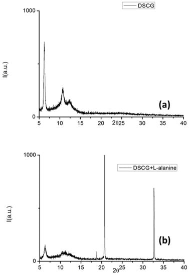
Figure 15.
XRD spectra of (a) pure DSCG and (b) DSCG doped with L-alanine.
Furthermore, when the solubility limit was reached, the chiral dopant was expelled from the phase giving rise to the L-alanine crystals.
Similar features were observed for DSCG doped with trans-Hyp [49]. Figure 16 shows that, at low angles, a peak corresponding to trans-Hyp was visible and, as in the previous case, this pointed to a phase separation. For both amino acids, the observations suggested that the chiral dopant was not intercalated inside the columns but probably bound to the external side of the supramolecular columnar structures. This fact could also explain the nematic core observed in the polarized light optical images of the microspheres. The chiral dopant was not intercalated in the supramolecular columns, and it was expelled from the central part of the microspheres. Nevertheless, the external binding seemed to be the most effective for inducing the chirality and obtaining the well-defined optical textures.
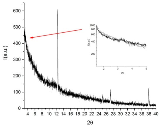
Figure 16.
XRD pattern of pure DSCG doped with trans-Hyp. Reprinted from [49].
Finally, there was a factor common to all the observed samples. The slow water evaporation caused the textures to degrade slowly, and this was the main problem that prevented these materials from being used for applications (Figure 17a–c). If the microspheres are stored at room temperature, textures would deteriorate after approximately 2 weeks. The degradation time is dependent on the temperature and humidity of the environment. If refrigerated at 4 °C, the texture would be preserved for two weeks.

Figure 17.
(a–c) Microsphere texture degradation. Reprinted with permission from ref. [37]. Copyright 2021, Wiley-VCH GmbH. (d) Free-standing PDMS film containing chromonic microspheres. Reprinted from [49].
The water evaporation can be slowed by simply polymerizing the PDMS matrix and obtaining a flexible film containing the microspheres (Figure 17d). In this case, the textures can be preserved for months. This aspect is important and could be exploited to create, for example, time temperature indicators that, if opportunely calibrated, could be used to monitor the cold food chain.
5.2. Chiral Induction in SSY
The chirality induction was also studied in Sunset Yellow using PDMS as the confining matrix [50], and it was strongly dependent on the type of amino acid that was used. Figure 18 shows the textures obtained in the microspheres containing L-alanine (Figure 18a), L-lysine (Figure 18b) and trans-Hyp (Figure 18c) dispersed in a paraffin matrix. Only after doping with the high twisting power trans-Hyp, a torsion in the texture was visible at the borders of the droplet.

Figure 18.
Sunset Yellow 30 wt% in paraffin oil doped with (a) L-alanine 10 wt%, (b) L-lysine 10 wt%. and (c) trans-Hyp 26 wt%. Reprinted with permission from ref. [50]. Copyright 2022, Elsevier.
A richer variety of textures was observed when PDMS was used as the confining matrix. PDMS imposed an homeotropic alignment to Sunset Yellow. In the spherical confinement, this favored the formation of chiral SSY for the topologies observed only in a chiral thermotropic liquid crystal in the same type of confinement. As an example, when doping with L-lysine, toron-like structures and intermediate layer-like textures were observed (Figure 19). While doping SSY with trans-Hyp, layer-like textures and Frank–Pryce-like textures were observed.
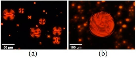
Figure 19.
(a) POM images of the microspheres containing SSY doped with L-Lysine 10 wt% in PDMS, showing a toron-like texture and an intermediate layer-like structure and (b) SSY with trans-Hyp 26 wt%, showing a Frank–Pryce-like texture. (a,b) Reprinted with permission from ref. [50]. Copyright 2022, Elsevier.
The XRD spectra acquired on the dried films of both SSY and SSY doped with L-lysine on the thin PDMS layers are shown in Figure 20. The XRD pattern of the pure SSY exhibited peaks related to the hexagonal mesophase. Both low and high angle peaks, which were related to the intercolumnar (17.7 Å) and stacking distance (3.43 Å), respectively, were visible, suggesting that the columnar structures did not have a preferred orientation, lying either perpendicular or planar on the PDMS surface.
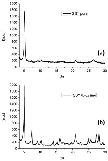
Figure 20.
XRD pattern of (a) pure SSY and (b) SSY doped with L-lysine.
For SSY doped with L-Lysine, the diffraction pattern showed well-defined peaks and several features in the high angle region. This was due to the incorporation of SSY into the columnar aggregates, i.e., the presence of SSY led to an increase order in the structure. This points to the fact that the L-Lysine effect on the SSY liquid crystal phase was to shorten the rigid cylinders or increase the flexibility of the long cylinders. It is well known that SSY, as a sulfonated dye, hardly crystallizes without the presence of co-adjuvants that can help in the crystallization process [51]. In this case, L-Lysine acted as a co-adjuvant in the formation of a crystalline-like film.
The interaction of SSY with trans-Hyp was completely different. The XRD pattern showed a residual 2D/3D SSY order for low diffraction angles (highlighted by the blue circle), while the small red lines marked the proper peaks of the trans-Hyp [52] (Figure 21).
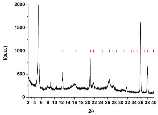
Figure 21.
XRD pattern of SSY doped with trans-Hyp (black), crystallographic peaks of trans.Hyp (red). Reprinted with permission from ref. [50]. Copyright 2022, Elsevier.
It is, therefore, clear that L-Lysine and trans-Hyp interacted with SSY in a different manner with the second mechanism of interaction being more efficient in order to induce the chirality in the system [53].
6. Applications
The applications in optics for chromonic liquid crystals in planar geometries have been extensively reported [54]. In the form of dried thin films, chromonics can be exploited as linear polarizers, optical compensators, retarders, alignment layers and color filters [tam chang]. As an example, a shear-induced orientation can be used to align the chromonic N phase. Following the solvent evaporation, the polarizing films with a dichroic ratio as high as 30 can be obtained [55,56] and, using the appropriate materials, the films may also show a polarized fluorescent emission [57].
In general, all the applications demand a homogeneous and stable alignment on anisotropic surfaces, a condition that is difficult to achieve [58]. At present, a good alignment of chromonics, both planar and homeotropic, on large areas cannot be obtained without the presence of defects and stability issues. Recently, van der Asdonk and co-workers presented a technique that could overcome this limit [59]. The authors supposed that the alignment problem was mainly related to the hydrophobic/hydrophilic mismatch between the substrates and chromonics, since the alignment surfaces are often hydrophobic while the in-plane aligned liquid crystalline assemblies are covered in hydrophilic groups on the outside. Following this idea, the quality and stability of the planar alignment of chromonics can be improved, adding a small amount of a non-ionic surfactant. The samples with surfactant showed an excellent alignment that was stable for months without any loss in the alignment quality. Using the same approach, well-aligned dry films of chromonics can also be obtained.
Chromonics have also been proposed for applications as biosensors. In 2005, Shiyanovskii et al. presented a sensor composed of a chromonic liquid crystal sandwiched between two rubbed polyimide coated glasses that was observed between crossed polarizers [60]. The authors showed that the distortions of the nematic chromonic director around a spherical particle with a planar surface orientation and the consequent light transmittance through the distorted region was a steep function of the particle’s size. For their experiments, they used a chromonic nematic liquid crystal containing antigen-coated latex beads and an antibody. The specific recognition of the antigen by the antibody resulted in the agglomeration of the latex beads in the large particles. The presence of these agglomerates caused a director distortion around them that could be easily detected using polarized light microscopy.
Recently, the use of chromonic thin films as humidity sensors was proposed [61]. Glushchenko and co-workers demonstrated that the sensing properties related to the self-assembling properties of solid chromonic films as a function of the humidity of the surrounding air. In the dry films, the stacking distance in the molecular aggregates depended on the water content of the ambient atmosphere that modified the weak non-covalent hydrophobic and hydrophilic interactions between the molecular groups. Applying an electric field, a variation of the humidity and, consequently, the stacking distance, caused a dramatic change in the electric current passing through the aggregate that could be easily detected.
The application of chiral chromonics in spherical geometries has not yet been investigated. However, it could also be foreseen in the field of sensors, for example, as time temperature indicators (TTIs). A TTI is a device or smart label that accumulates the time–temperature history of a material. This type of devices is extremely important, as an example, for the monitoring of the food cold chain to ensure food safety and freshness.
There are two types of TTIs, namely, diffusion-based and chemical reaction-activated [62]. Diffusion-based TTIs are composed of a temperature phase-change dye and a porous material. When the dye melts due to high temperatures, it permeates the porous materials. Chemical reaction-activated TTIs are based on a color change induced by the reactions of a chemical component activated above a specific temperature. Unfortunately, both types of TTIs have their respective critical disadvantages due to construction constraints, scarce sensitivity or chemical substance leakage issues.
Chromonic liquid crystals have the potential to be applied as TTIs that lay on the director distortions arising from the aligned chromonic phases reflected in colorful optical textures that are temperature dependent.
As an example, chiral chromonic microspheres were successfully trapped in a polymeric free-standing film [49]. Storage at 4 °C allowed the textures to be maintained for at least 10 days, after which their degradation process began. The degradation was irreversible and it was impossible to recover the initial condition. The texture could be preserved for longer if the film was kept at −20 °C, and this could be used to detect temperature variations. The fact that these materials were perfectly biocompatible was ideal since there was no safety issue when they came into in contact with food or medicines.
7. Conclusions
This review was devoted to the last experimental results obtained in the field of chiral chromonic liquid crystals confined in spherical geometries. In the scientific community, there is a growing interest in studying the fundamental properties of these water-based materials in this highly symmetrical confinement that allows researchers to amplify their peculiar elastic properties.
After a quick introduction on the self-assembly properties of chromonics, we focused on the optical textures that are observed on thermotropic chiral liquid crystals when confined in spherical geometry. This step was necessary as the textures are explained in terms of the director configuration inside the microspheres and it helps in understanding the supramolecular aggregates configuration in nematic and chiral chromonics. In this perspective, the experimental results obtained on native chiral chromonics in the same type of confinement were reported. Finally, a complete description of the behavior of the two model chromonics confined in the microspheres, DSCG and SSY, using different confining matrices and doping them with different chiral dopants, was reported.
The experiments carried out on DSCG showed that the typical textures observed in thermotropic liquid crystals, for example the Frank–Pryce, could be obtained in chiral chromonics. This was an important achievement since a similar structure previously was reported only for native chiral chromonics as cellulose nanocrystals.
To highlight the role of chiral dopants in the torsion of the supramolecular aggregates, X-ray diffraction experiments were carried out and it was found that the chiral molecules tend to bind to the outside of the DSCG cylindrical aggregates, favoring their twist. This result was confirmed for two amino acids: L-alanine and trans-Hyp.
On the other hand, SSY was demonstrated to be a material that the supramolecular aggregates were difficult to torque, and the effect of the chiral dopants were dependent on the type of amino acid used.
One of the main differences between DSCG and SSY was their molecular flexibility, which could be the key parameter for the design of new materials in which the chirality could be easily amplified. Overall, these results can be useful in fundamental studies of the defects in the frustrated liquid crystalline phases and may foster the development of new chromonic liquid crystals.
Finally, chromonics are not yet used for practical applications due to issues in their stability, even if, in recent years, their use as sensors has been foreseen. At present, no application of these materials in their chiral nematic phase has been envisaged. However, the present results could lead to their application in the temperature sensor field.
Author Contributions
Conceptualization, M.P.D.S. and F.C.; methodology, M.P.D.S. and F.C.; writing—original draft preparation, M.P.D.S. and F.C.; writing—review and editing, M.P.D.S., L.S. and F.C.; supervision, M.P.D.S. and F.C. All authors have read and agreed to the published version of the manuscript.
Funding
This work was supported by the following projects: PON ARS01_00401-DEMETRA, CUP: B24I20000080001. L.S. wishes to acknowledge the support from MIUR, PON ARS01_00568-“SI.F.I.PA.CRO.DE.”, CUP: B29C20000360005.
Institutional Review Board Statement
Not applicable.
Informed Consent Statement
Not applicable.
Data Availability Statement
Data sharing not applicable.
Conflicts of Interest
The authors declare no conflict of interest.
References
- Grelet, E.; Fraden, S. What Is the Origin of Chirality in the Cholesteric Phase of Virus Suspensions? Phys. Rev. Lett. 2003, 90, 198302. [Google Scholar] [CrossRef] [PubMed]
- Tortora, L.; Lavrentovich, O.D. Chiral symmetry breaking by spatial confinement in tactoidal droplets of lyotropic chromonic liquid crystals. Proc. Natl. Acad. Sci. USA 2011, 108, 5163–5168. [Google Scholar] [CrossRef] [PubMed]
- Nayani, K.; Fu, J.; Chang, R.; Park, J.O.; Srinivasarao, M. Using chiral tactoids as optical probes to study the aggregation behavior of chromonics. Proc. Natl. Acad. Sci. USA 2017, 114, 3826–3831. [Google Scholar] [CrossRef] [PubMed]
- Jeong, J.; Kang, L.; Davidson, Z.S.; Collings, P.J.; Lubensky, T.C.; Yodh, A.G. Chiral structures from achiral liquid crystals in cylindrical capillaries. Proc. Natl. Acad. Sci. USA 2015, 112, E1837–E1844. [Google Scholar] [CrossRef] [PubMed]
- Peng, C.; Lavrentovich, O.D. Chirality amplification and detection by tactoids of lyotropic chromonic liquid crystals. Soft Matter 2015, 11, 7257–7263. [Google Scholar] [CrossRef]
- Orlova, T.; Aßhoff, S.J.; Yamaguchi, T.; Katsonis, N.; Brasselet, E. Creation and manipulation of topological states in chiral nematic microspheres. Nat. Commun. 2015, 6, 7603. [Google Scholar] [CrossRef]
- Zhou, Y.; Bukusoglu, E.; Martínez-González, J.A.; Rahimi, M.; Roberts, T.F.; Zhang, R.; Wang, X.; Abbott, N.L.; de Pablo, J.J. Structural Transitions in Cholesteric Liquid Crystal Droplets. ACS Nano 2016, 10, 6484–6490. [Google Scholar] [CrossRef]
- Posnjak, G.; Čopar, S.; Muševič, I. Points, skyrmions and torons in chiral nematic droplets. Sci. Rep. 2016, 6, 26361. [Google Scholar] [CrossRef]
- Sleczkowski, P.; Zhou, Y.; Iamsaard, S.; de Pablo, J.J.; Katsonis, N.; Lacaze, E. Light-activated helical inversion in cholesteric liquid crystal microdroplets. Proc. Natl. Acad. Sci. USA 2018, 115, 4334–4339. [Google Scholar] [CrossRef]
- Humar, M.; Muševič, I.; Sullivan, K.G.; Hall, D.G. 3D microlasers from self-assembled cholesteric liquid-crystal microdroplets. Opt. Express 2010, 18, 26995–27003. [Google Scholar] [CrossRef]
- Petriashvili, G.; De Santo, M.P.; Hernandez, R.J.; Barberi, R.; Cipparrone, G. Mixed emulsion of liquid crystal microresonators: Towards white laser systems. Soft Matter 2017, 13, 6227–6233. [Google Scholar] [CrossRef] [PubMed]
- Gardiner, D.J.; Morris, S.M.; Hands, P.J.W.; Mowatt, C.; Rutledge, R.; Wilkinson, T.D.; Coles, H.J. Paintable band-edge liquid crystal lasers. Opt. Express 2011, 19, 2432–2439. [Google Scholar] [CrossRef] [PubMed]
- Petriashvili, G.; Bruno, M.D.L.; De Santo, M.P.; Barberi, R. Temperature-tunable lasing from dye-doped chiral microdroplets encapsulated in a thin polymeric film. Beilstein J. Nanotechnol. 2018, 9, 379–383. [Google Scholar] [CrossRef] [PubMed]
- Lee, H.-G.; Munir, S.; Park, S.-Y. Cholesteric Liquid Crystal Droplets for Biosensors. ACS Appl. Mater. Interfaces 2016, 8, 26407–26417. [Google Scholar] [CrossRef]
- Petriashvili, G.; Bruno, M.D.L.; De Santo, M.P.; Fuoco, E.; Barberi, R. Acid mediated tunability of stimulated laser emission from dye doped chiral microdroplets. Mol. Cryst. Liq. Cryst. 2019, 684, 82–88. [Google Scholar] [CrossRef]
- Geng, Y.; Noh, J.; Drevensek-Olenik, I.; Rupp, R.; Lenzini, G.; Lagerwall, J.P.F. High-fidelity spherical cholesteric liquid crystal Bragg reflectors generating unclonable patterns for secure authentication. Sci. Rep. 2016, 6, 26840. [Google Scholar] [CrossRef]
- Wang, P.-X.; Hamad, W.Y.; MacLachlan, M.J. Polymer and Mesoporous Silica Microspheres with Chiral Nematic Order from Cellulose Nanocrystals. Angew. Chem. Int. Ed. 2016, 55, 12460–12464. [Google Scholar] [CrossRef]
- Gaspar, A.; Matos, M.J.; Garrido, J.; Uriarte, E.; Borges, F. Chromone: A Valid Scaffold in Medicinal Chemistry. Chem. Rev. 2014, 114, 4960–4992. [Google Scholar] [CrossRef]
- Lydon, J. Chromonic liquid crystalline phases. Liq. Cryst. 2011, 38, 1663–1681. [Google Scholar] [CrossRef]
- Lydon, J. Chromonic liquid crystal phases. Curr. Opin. Colloid Interface Sci. 1998, 3, 458–466. [Google Scholar] [CrossRef]
- Collings, P.J.; Goldstein, J.N.; Hamilton, E.J.; Mercado, B.R.; Nieser, K.J.; Regan, M.H. The nature of the assembly process in chromonic liquid crystals. Liq. Cryst. Rev. 2015, 3, 1–27. [Google Scholar] [CrossRef]
- Mohanty, S. Chromonics: Reviewing a High-performance Self-assembling Structure. Indian Chem. Eng. 2011, 53, 84–94. [Google Scholar] [CrossRef]
- Lombardo, D.; Kiselev, M.A.; Magazù, S.; Calandra, P. Amphiphiles Self-Assembly: Basic Concepts and Future Perspectives of Supramolecular Approaches. Adv. Condens. Matter Phys. 2015, 2015, 151683. [Google Scholar] [CrossRef]
- Zhang, B.; Kitzerow, H.-S. Influence of Proton and Salt Concentration on the Chromonic Liquid Crystal Phase Diagram of Disodium Cromoglycate Solutions: Prospects and Limitations of a Host for DNA Nanostructures. J. Phys. Chem. B 2016, 120, 3250–3256. [Google Scholar] [CrossRef] [PubMed]
- Cox, J.; Woodard, G.; McCrone, W. Solid-State Chemistry of Cromolyn Sodium (Disodium Cromoglycate). J. Pharm. Sci. 1971, 60, 1458–1465. [Google Scholar] [CrossRef] [PubMed]
- Yamaguchi, A. Self-Assembly of Lyotropic Chromonic Liquid Crystal Mixtures. Bachelor’s Thesis, Bachelor University of Colorado Boulder, Boulder, CO, USA, 2015. [Google Scholar]
- Edwards, D.J.; Jones, J.W.; Lozman, O.; Ormerod, A.P.; Sintyureva, M.; Tiddy, G.J.T. Chromonic Liquid Crystal Formation by Edicol Sunset Yellow. J. Phys. Chem. B 2008, 112, 14628–14636. [Google Scholar] [CrossRef]
- Bao, P.; Paterson, D.A.; Peyman, S.A.; Jones, J.C.; Sandoe, J.A.T.; Gleeson, H.F.; Evans, S.D.; Bushby, R.J. Production of giant unilamellar vesicles and encapsulation of lyotropic nematic liquid crystals. Soft Matter 2021, 17, 2234–2241. [Google Scholar] [CrossRef]
- de Gennes, P.G.; Prost, J. The Physics of Liquid Crystals; Oxford University press: Oxford, UK, 1994. [Google Scholar]
- Zhou, S.; Neupane, K.; Nastishin, Y.A.; Baldwin, A.R.; Shiyanovskii, S.V.; Lavrentovich, O.D.; Sprunt, S. Elasticity, viscosity, and orientational fluctuations of a lyotropic chromonic nematic liquid crystal disodium cromoglycate. Soft Matter 2014, 10, 6571–6581. [Google Scholar] [CrossRef]
- Zhou, S. Lyotropic Chromonic Liquid Crystals: From Viscoelastic Properties to Living Liquid Crystals; Springer International Publishing: Berlin/Heidelberg, Germany, 2017; Volume 95, p. XXIII. [Google Scholar]
- Urbanski, M.; Reyes, C.G.; Noh, J.; Sharma, A.; Geng, Y.; Jampani, V.S.R.; Lagerwall, J.P.F. Liquid crystals in micron-scale droplets, shells and fibers. J. Phys. Condens. Matter 2017, 29, 133003. [Google Scholar] [CrossRef]
- Cipparrone, G.; Mazzulla, A.; Pane, A.; Hernandez, R.J.; Bartolino, R. Chiral Self-Assembled Solid Microspheres: A Novel Multifunctional Microphotonic Device. Adv. Mater. 2011, 23, 5773–5778. [Google Scholar] [CrossRef]
- Aβhoff, S.J.; Sukas, S.; Yamaguchi, T.; Hommersom, C.A.; Le Gac, S.; Katsonis, N. Superstructures of chiral nematic microspheres as all-optical switchable distributors of light. Sci. Rep. 2015, 5, 14183. [Google Scholar] [CrossRef] [PubMed]
- Tomar, V.; Hernández, S.I.; Abbott, N.L.; Hernández-Ortiz, J.P.; de Pablo, J.J. Morphological transitions in liquid crystal nanodroplets. Soft Matter 2012, 8, 8679–8689. [Google Scholar] [CrossRef]
- Lopez-Leon, T.; Fernandez-Nieves, A. Drops and shells of liquid crystal. Colloid Polym. Sci. 2011, 289, 345–359. [Google Scholar] [CrossRef]
- Krakhalev, M.N.; Rudyak, V.Y.; Prishchepa, O.O.; Gardymova, A.P.; Emelyanenko, A.V.; Liu, J.-H.; Zyryanov, V.Y. Orientational structures in cholesteric droplets with homeotropic surface anchoring. Soft Matter 2019, 15, 5554–5561. [Google Scholar] [CrossRef]
- Krakhalev, M.N.; Gardymova, A.P.; Prishchepa, O.O.; Rudyak, V.Y.; Emelyanenko, A.V.; Liu, J.-H.; Zyryanov, V.Y. Bipolar configuration with twisted loop defect in chiral nematic droplets under homeotropic surface anchoring. Sci. Rep. 2017, 7, 14582. [Google Scholar] [CrossRef]
- Krakhalev, M.N.; Gardymova, A.P.; Emel’Yanenko, A.V.; Liu, J.-H.; Zyryanov, V.Y. Untwisting of the helical structure of cholesteric droplets with homeotropic surface anchoring. JETP Lett. 2017, 105, 51–54. [Google Scholar] [CrossRef]
- Jeong, J.; Davidson, Z.S.; Collings, P.J.; Lubensky, T.C.; Yodh, A.G. Chiral symmetry breaking and surface faceting in chromonic liquid crystal droplets with giant elastic anisotropy. Proc. Natl. Acad. Sci. USA 2014, 111, 1742–1747. [Google Scholar] [CrossRef]
- Li, Y.; Suen, J.J.-Y.; Prince, E.; Larin, E.M.; Klinkova, A.; Thérien-Aubin, H.; Zhu, S.; Yang, B.; Helmy, A.S.; Lavrentovich, O.D.; et al. Colloidal cholesteric liquid crystal in spherical confinement. Nat. Commun. 2016, 7, 12520. [Google Scholar] [CrossRef]
- Tixier, T.; Heppenstall-Butler, M.; Terentjev, E.M. Stability of cellulose lyotropic liquid crystal emulsions. Eur. Phys. J. E 2005, 18, 417–423. [Google Scholar] [CrossRef]
- Fumeron, S.; Moraes, F.; Pereira, E. Retrieving the saddle-splay elastic constant K24 of nematic liquid crystals from an algebraic approach. Eur. Phys. J. E 2016, 39, 83. [Google Scholar] [CrossRef]
- Frank, F.C. On the theory of liquid crystals. Discuss. Faraday Soc. 1958, 25, 19–28. [Google Scholar] [CrossRef]
- Zhou, S.; Cervenka, A.J.; Lavrentovich, O.D. Ionic-content dependence of viscoelasticity of the lyotropic chromonic liquid crystal sunset yellow. Phys. Rev. E 2014, 90, 042505. [Google Scholar] [CrossRef] [PubMed]
- Shirai, T.; Shuai, M.; Nakamura, K.; Yamaguchi, A.; Naka, Y.; Sasaki, T.; Clark, N.A.; Le, K.V. Chiral lyotropic chromonic liquid crystals composed of disodium cromoglycate doped with water-soluble chiral additives. Soft Matter 2018, 14, 1511–1516. [Google Scholar] [CrossRef] [PubMed]
- Lee, H.; Labes, M.M. Helical Twisting Power of Amino Acids in a Nematic Lyophase. Mol. Cryst. Liq. Cryst. 1984, 108, 125–132. [Google Scholar] [CrossRef]
- Pellegrino, C.; De Santo, M.P.; Spina, L.; Ciuchi, F. Induced Chiral Chromonics Confined in Micrometric Droplets. Adv. Funct. Mater. 2021, 31, 2010394. [Google Scholar] [CrossRef]
- Spina, L.; Ciuchi, F.; Tone, C.M.; Barberi, R.; De Santo, M.P. Spherical Confinement of Chromonics: Effects of a Chiral Aminoacid. Nanomaterials 2022, 12, 619. [Google Scholar] [CrossRef]
- Spina, L.; De Santo, M.P.; Tone, C.M.; Pisani, M.; Vita, F.; Barberi, R.; Ciuchi, F. Intercalation or external binding: How to torque chromonic Sunset Yellow. J. Mol. Liq. 2022, 359, 119265. [Google Scholar] [CrossRef]
- Xiao, W.; Hu, C.; Carter, D.J.; Nichols, S.; Ward, M.D.; Raiteri, P.; Rohl, A.L.; Kahr, B. Structural Correspondence of Solution, Liquid Crystal, and Crystalline Phases of the Chromonic Mesogen Sunset Yellow. Cryst. Growth Des. 2014, 14, 4166–4176. [Google Scholar] [CrossRef]
- Thirumurugan, R.; Anitha, K. Growth, structural, physical and computational perspectives of trans-4-hydroxy-l-proline: A promising organic nonlinear optical material with large laser-induced damage threshold. Mater. Res. Express 2017, 4, 056202. [Google Scholar] [CrossRef]
- Ahmad, H.; Wragg, A.; Cullen, W.; Wombwell, C.; Meijer, A.J.H.M.; Thomas, J.A. From Intercalation to Groove Binding: Switching the DNA-Binding Mode of Isostructural Transition-Metal Complexes. Chem.-A Eur. J. 2014, 20, 3089–3096. [Google Scholar] [CrossRef]
- Tam-Chang, S.-W.; Huang, L. Chromonic liquid crystals: Properties and applications as functional materials. Chem. Commun. 2008, 17, 1957–1967. [Google Scholar] [CrossRef] [PubMed]
- Iverson, I.K.; Tam-Chang, S.-W. Cascade of Molecular Order by Sequential Self-Organization, Induced Orientation, and Order Transfer Processes. J. Am. Chem. Soc. 1999, 121, 5801–5802. [Google Scholar] [CrossRef]
- Iverson, I.K.; Casey, S.M.; Seo, W.; Tam-Chang, S.-W.; Pindzola, B.A. Controlling Molecular Orientation in Solid Films via Self-Organization in the Liquid-Crystalline Phase. Langmuir 2002, 18, 3510–3516. [Google Scholar] [CrossRef]
- Carson, T.D.; Seo, W.; Tam-Chang, S.-W.; Casey, S.M. Novel Polarized Photoluminescent Films Derived from Sequential Self-organization, Induced-Orientation, and Order-Transfer Processes. Chem. Mater. 2003, 15, 2292–2294. [Google Scholar] [CrossRef]
- Tone, C.M.; De Santo, M.P.; Ciuchi, F. Alignment of Chromonic Liquid Crystals: A Difficult Task. Mol. Cryst. Liq. Cryst. 2013, 576, 2–7. [Google Scholar] [CrossRef]
- van der Asdonk, P.; Collings, P.J.; Kouwer, P.H.J. Fully Stable and Homogeneous Lyotropic Liquid Crystal Alignment on Anisotropic Surfaces. Adv. Funct. Mater. 2017, 27, 1701209. [Google Scholar] [CrossRef]
- Shiyanovskii, S.V.; Lavrentovich, O.D.; Schneider, T.; Ishikawa, T.; Smalyukh, I.I.; Woolverton, C.J.; Niehaus, G.D.; Doane, K.J. Lyotropic Chromonic Liquid Crystals for Biological Sensing Applications. Mol. Cryst. Liq. Cryst. 2005, 434, 259–587. [Google Scholar] [CrossRef]
- Glushchenko, A.; Boiko, O.P.; Lenyk, B.Y.; Senenko, A.; Nazarenko, V.G. Humidity sensing with printable films of lyotropic chromonic liquid crystals. Appl. Phys. Lett. 2020, 117, 071902. [Google Scholar] [CrossRef]
- Liu, D.; Yang, L.; Shang, M.; Zhong, Y. Research progress of packaging indicating materials for real-time monitoring of food quality. Mater. Express 2019, 9, 377–396. [Google Scholar] [CrossRef]
Disclaimer/Publisher’s Note: The statements, opinions and data contained in all publications are solely those of the individual author(s) and contributor(s) and not of MDPI and/or the editor(s). MDPI and/or the editor(s) disclaim responsibility for any injury to people or property resulting from any ideas, methods, instructions or products referred to in the content. |
© 2023 by the authors. Licensee MDPI, Basel, Switzerland. This article is an open access article distributed under the terms and conditions of the Creative Commons Attribution (CC BY) license (https://creativecommons.org/licenses/by/4.0/).