1. Introduction
Machines have become essential for our lives, and faster, more complex, and automated machines are being developed to meet the evolving requirements of human beings. Recently, technologies that use cleaner fuel or reduce pollutants are being developed in the interests of being environmentally friendly [
1,
2,
3,
4,
5]. In the shipping and offshore industries, there are various types of equipment and many types of ships, e.g., cargo ships for transporting cargo, passenger ships to transport passengers, oil tankers for transporting crude oil, and LNG carriers to transport LNG. Even though various types of ships feature various differences, most of them share one common machine, i.e., the engine. A few ships do use fuel cells and electricity in order to be environmentally friendly, but this is a small number compared to all vessels operating at sea. According to the European Maritime Safety Agency, most failures occur in the engine room [
6]. Consequently, securing the safety of the ship’s engine room system is most important, and it is necessary for engines to be able to work smoothly, even in the face of minor breakdowns of some of its components [
7,
8,
9].
In past decades, maintenance technology for ships focused on prevention techniques for the planned maintenance system, which depends on component replacement after a certain period, regardless of the fault. However, such maintenance is carried out irrespective of the fault level; thus, it tends to be expensive owing to frequent interruption and part replacement. In particular, in the case of small ships, an alarm system installed on board is required to send alarm sounds or visual signals when a device is facing issues; however, it is difficult to pinpoint the exact issue if there is no professional knowledge of how the device is affected. Furthermore, there is an increased risk of marine accidents if a mechanical device has a problem. These problems arise in many other industries as well, and to mitigate them, increasingly, condition-based maintenance technology is being developed. The study of abnormal detection and classification is being actively conducted using various types of data from the machine to diagnose the condition of the machine with more specificity and exactness. This is expected to be able to reduce the maintenance cost by improving management technology and minimizing parts replacement by performing prediction maintenance in a timely manner. Currently, domestic and foreign ship failure diagnostic systems are being developed by engine manufacturers to perform monitoring and failure diagnosis of their own engines.
The International Maritime Organization (IMO) defines a maritime autonomous surface ship (MASS) as a vessel that can operate at a certain level without human intervention. It aims to be a full-time autonomous vessel, and for this purpose, failure diagnosis must be available in most equipment systems and the engine. A large amount of actual data on the target equipment is required to develop effective failure diagnostic technology for the ship engine system. However, existing ships have been carrying out post-maintenance and regular maintenance; thus, a database containing the appropriate data needs to be created. In addition, data collection on actual ships is time-consuming, making it challenging to develop such technology. The best way to do this is to build a state-based database based on land and demonstration tests. In the past few decades, fault monitoring of marine diesel engine-based equipment on ships has been widely reported [
10,
11]. Rubio [
12] investigated the development of a four-stroke high-speed marine diesel engine failure simulator used in military and civil vessels as the main engine of small patrols and yachts. This simulator was adjusted and validated using an experimental database from a real engine in a test bench. A thermodynamic model was developed that reproduces engine behavior not only under normal conditions but also under failure conditions [
12]. Radica and Matulic [
13] reported an engine model for onboard engine failure simulation. A physical model was built for engine optimization and diagnostic purposes that can be used onboard ships. The engine model was calibrated using a low-speed marine diesel engine, and the results were successfully verified against the measurement [
13]. Chybowsk et al. [
14] investigated the impact of marine engine component failures upon an explosion in the starting air manifold. A cause-and-effect analysis of the explosions was performed, and their root causes were identified. In addition, a probabilistic model of an explosion in the starting air manifold of a marine engine was built using a fault tree analysis [
14]. Wang et al. [
15] investigated the fault monitoring method of marine diesel engines. A hybrid fault monitoring scheme combining manifold learning and anomaly detection was proposed. The results showed that a zero-dimensional marine diesel engine simulation model realistically represented the behavior of the engine with acceptable parameter deviation [
15]. Gao et al. [
16] investigated the failure of gear teeth fracture of seawater pumps in a diesel engine. The results showed that the root reason of the failure was gear fatigue fracture, which was caused by non-metallic inclusions in the teeth. The condition monitoring and fault diagnosis system (CMFDS) installed on the engine captured some useful information, which provided crucial clues to diagnose and locate the fault [
16]. Kowalski et al. [
17] identified diagnostic signals in the composition of exhaust gas from marine four-stroke diesel engines. An active experiment was performed that consisted of measurements conducted during a laboratory-based engine operation with simulated malfunctions [
17]. Karatug and Arslanoglu [
18] reported the condition-based maintenance strategy for fault diagnosis for ship engine systems. Certain parameters of the large-sized container ship are collected for the development of the condition-based maintenance strategy. These data were analyzed using an artificial neural network in order to create an engine performance model [
18].
A number of related studies have been reported, but a database focused extensively on parts related to pumps, which play an important role in the engine room, has not been developed. Furthermore, it is difficult to find studies that have established an infrastructure capable of evaluating the performance of a pump and analyzed its behavior in normal and abnormal conditions using this infrastructure. In the present study, experimental research was conducted to build a condition-based ship device database. The failure mode was selected by analyzing the failure case and reliability analysis of the pump, which is an essential system. Fault scenarios were derived through several studies on how to test failure modes. The test bed for the land test was established for the fault test. In addition, a performance monitor was used to obtain the actual monitoring and measurement data using the system, and the data characteristics of the time and frequency region were observed using vibration data.
2. Target Structure
The pump, an autonomous vessel assistant device, is a core assistive device of the engine room that supplies refined oil to the engine. There are various types of pumps. The pump selected in this study is the three-axis screw-type pump, which is used to supply clean oil purified by a purifier in the engine room of the ship. It needs to have stable operation characteristics because it supplies high-viscosity ship oil.
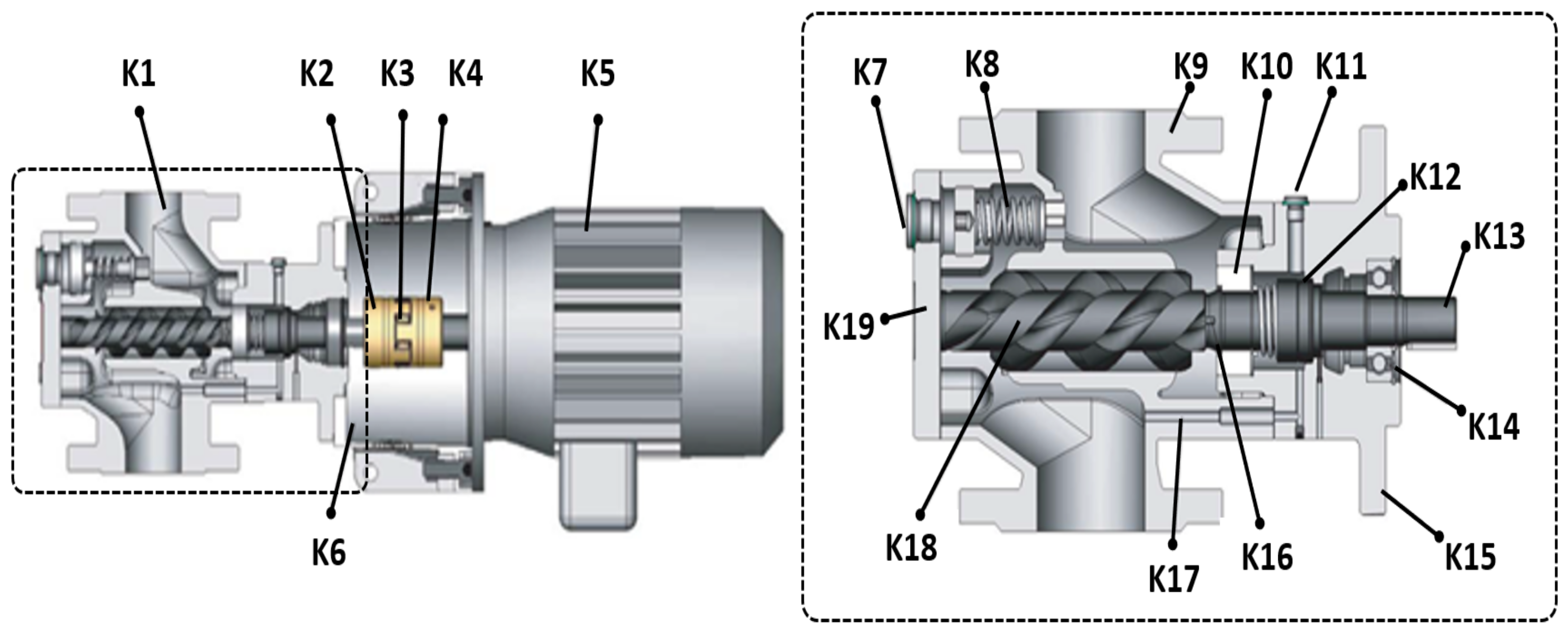
Figure 1 shows the cross-section of the tested screw-type pump. In addition,
Table 1 describes the main composition of each part of the pump in
Figure 1 [
19]. As shown, the pump is composed of various different parts, such as the coupling, motor, sealing, and bearing. The pump continues to operate during ship operations, and if a breakdown occurs, the supply of the oil decreases, which can interfere with smooth engine operations and cause subsequent failures. The ship oil used for ship operations has high viscosity and can be operated in a high-temperature environment, and the three-axis screw type pump has a stable operation even in the high-point and high-temperature environment. The maximum pressure of the target pump is 16 bar when media such as polyol, isocyanate, and lubricating oil are used. However, the manufacturer suggests an operating pressure up to 8 bar for safety (with a delivery rate of 50 L/min) when heavy fuel oil (HFO) is used as the medium. Motor bearings and pump bearings, couplings, sealings, and main screws are known to be the major components with high risk priority number (RPN) scores in the pump.
3. Analysis of Failure Mode
The main failure modes of the pump were analyzed using various studies [
20]. In addition, the cause and mechanism of failure for major components were analyzed.
Table 2 shows the failure mode of oil pumps installed on ships. For the core modules classified by function, the failure modes and corresponding failure mechanisms were summarized. We confirmed that there are various failure modes, such as crack, wear, adhesion, vibration, and leakage. In addition, the failure mechanism in each component was different for each failure mode. The FMECA (failure modes, effects, and critical analysis) is a way to determine all the possible failure modes for components of the system and to evaluate and optimize the risk of potential failure modes, failure effects, and causes of failure. According to the critical evaluation criteria, the incidence and severity of the failure derived from the literature data analysis were quantified and applied. RPN was evaluated, and the main failure mode was derived.
Table 3 shows the failure modes and mechanisms for each part of the pump. As shown, the core parts selected are the bearing, coupling, sealing, and screw.
In addition, we analyzed the proportion of the causes of failure in the main parts by referring to the documentary database. The incidence of failure by failure mode was evaluated through quantitative evaluation, and the main failure mode was selected for parts with high RPN scores.
4. Test Bed
Acquiring the actual data of the normal and abnormal components of the pump would take considerable time and would be expensive. Instead, a test bed was established to implement each major failure characteristic and acquire data considering the operating environments of the parts of the pump.
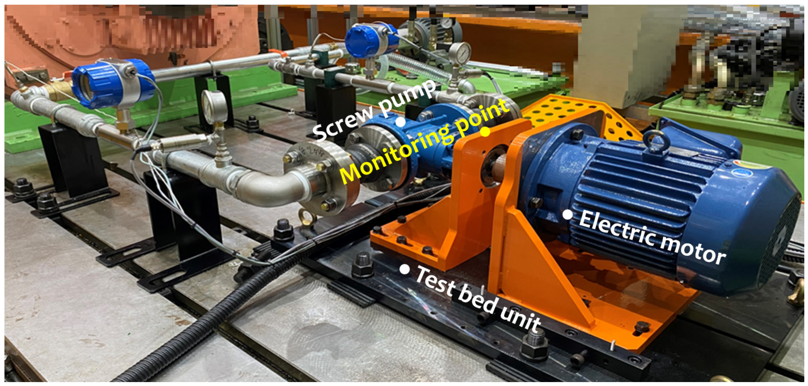
Figure 2 shows the test bed for collecting normal and abnormal data from the parts of the pump. As shown in the figure, the test bed on land was built as an individual system, unlike the multi-connected system configuration, to monitor the pump’s functional parts [
21].
Table 4 presents the measurement ranges, error ranges, and sampling rate information for sensors installed on the equipment, such as the flowmeter, pressure gauge, thermometer, and accelerometer.
The pump test bed is designed to control normal and abnormal characteristics precisely. In line with the advice of the manufacturer, the test facility was optimized and upgraded to verify its suitability for the test. More specifically, the piping design conditions were optimized to stably implement the operating conditions (flow rate, etc.) of the target device by performing a preliminary operation. In addition, uncertainty-inducing factors, such as cavitation, that could affect the operating environment were eliminated to accurately control and measure the flow rates. Using the installed sensors, the database was obtained considering environmental parameters such as temperature and pressure flow. In addition, the additional failure response for vibration and noise was acquired. The data were collected and stored in CSV data files through simultaneous modules such as the DAQ Card module and Sinus Apollo Light module [
22].
Table 5 presents information about the manufacturer and operating conditions of the pump test bed. The test bed was prepared using a screw pump (KRAL company), which is commonly used in ships. Then, a trial test was conducted to confirm whether the performance and safety of the equipment were secured and whether the operating environment could be reproduced. Fault test diagnostic data acquisition and system control software was configured to enable monitoring of driving data 16CH and vibration characteristic data 8ch. In addition, the operation of the development SW enabled real-time analysis of acquisition signals, such as the acquisition of failure diagnostic data for each failure scenario and FFT analysis. Vibration data were used in real-time monitoring of high frequency bands using Amadeus software (FAMTECH), and the application of the condition-based monitoring system was verified by comparing data using the development software. The test was conducted three times for 900 s.
5. Failure Tests
5.1. Motor Bearing
During the motor operation, the bearing is located at the end of the motor and maintains a smooth rotation. The bearing, combined with the motor, is exposed to high stress levels during the motor operation. Therefore, the proper lubricating conditions must be maintained, and the penetration of external pollutants must be prevented. When the motor has been operating for a long time, friction may occur between bearing components owing to poor lubrication or aging of the lubrication. In addition, the penetration of foreign substances and piling up on the inside of the bearing results in the adhesion of the bearing. In this case, subsequent failures such as vibration and noise due to bearing rotation and faults in operating the equipment may occur. In the present study, the bearing sample was subjected to lubrication failure and foreign substance injection failure to collect data for a quantitative database.
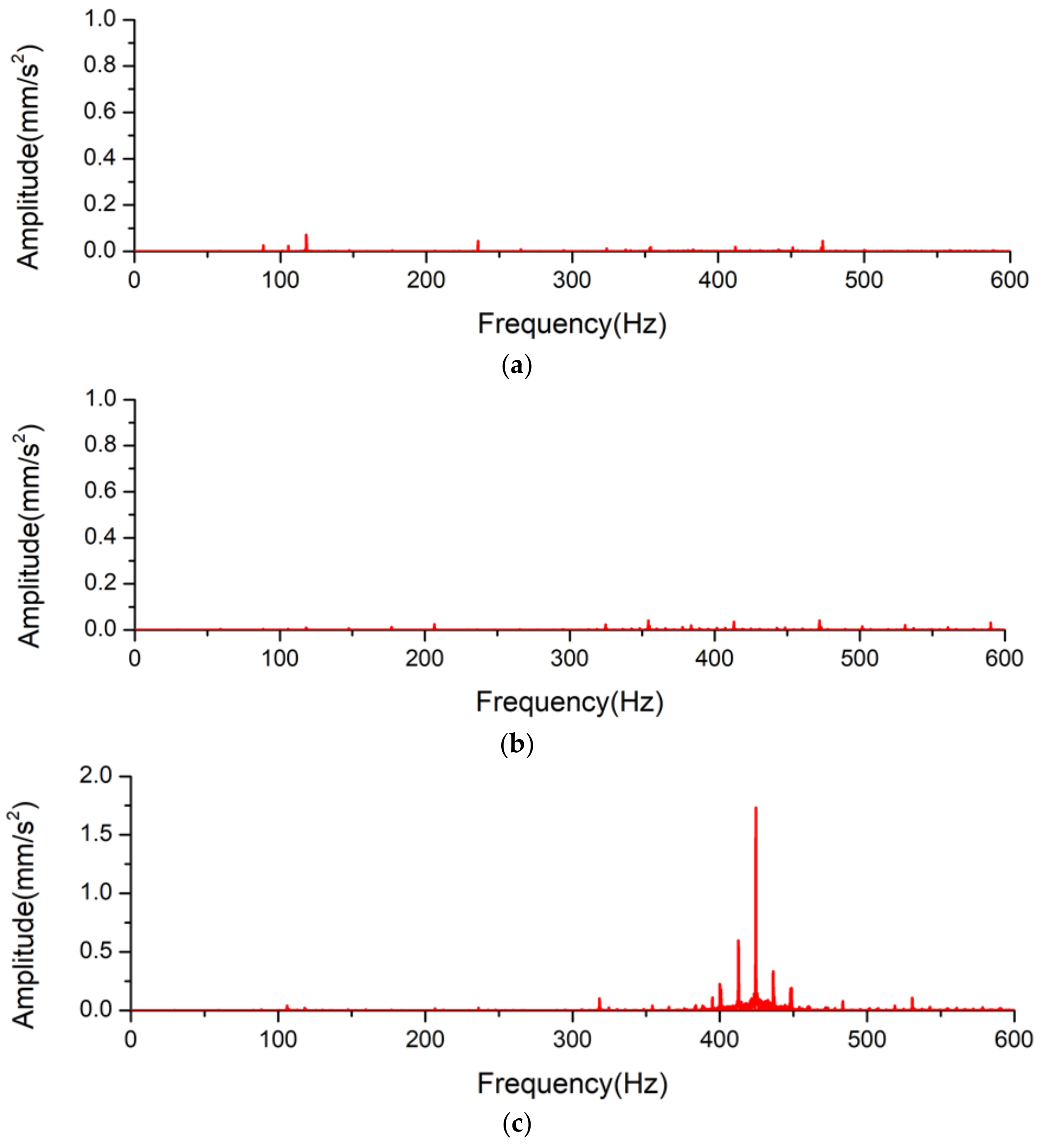
Figure 3a shows the results of the vibration data in the normal and abnormal states. In the case of
Figure 3b, the vibration occurred in each frequency band, similar to a normal database. In addition, the amplitude has been decreased in all areas of the motor in the radial direction. However, over 400 Hz, it can be confirmed that the vibration was slightly increased.
Figure 3c shows the vibration data according to the contamination state inside the motor bearing. Overall, it was confirmed that vibration occurs in the frequency band similar to the normal condition. However, it was confirmed that the amplitude near 400–450 Hz in the radial direction increased significantly owing to the high-speed rotation. Based on
Figure 3, it was confirmed that the severity of the vibration of the motor bearing was more dependent on the state of contamination inside the motor bearing rather than the absence of lubrication. This is thought to be due to an immediate reaction when pollutants are generated. However, once the motor is operated over a longer time period, it is expected that more severe problems will occur, such as heat generation, wear, and adhesion of the bearing.
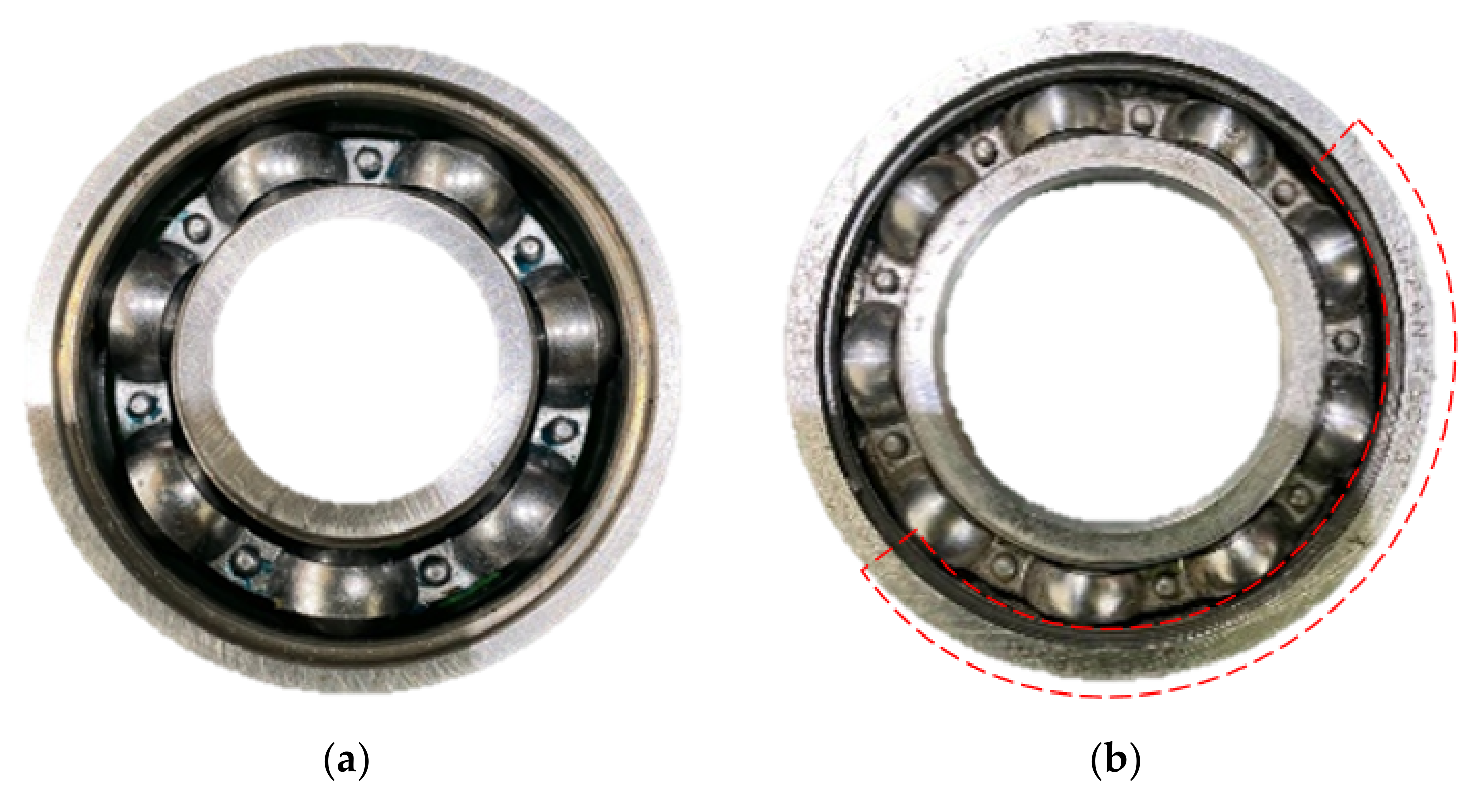
Figure 4 shows examples of wear, scratches, and dents that appear on the bearing by comparing the conditions prior to testing and the tested conditions. After the test, several scratches and dents were found in several places on the motor bearing. In particular, the wear, scratches, and dents appeared on the outer surface of the inner ring and on the inner surface of the outer ring after the test.
5.2. Coupling
The coupling has a structure in which an elastic body is inserted between the hub that transmits power and the hub that receives the power. The driver hub of the coupling is operated by the motor and transmits the power of the driver by pushing the elastic body and the driven hub. The elastic body inserted between the hubs can reduce noise, vibration, and impact during operation. As the surface of the elastic body is the curved surface, the contact area of the coupling hub and the elastic chain improves the torque density and increases the vibration damping effect. The pump for the fuel supplying system of ship is rotated at high speed, and once the pump is operated in a long or harsh environment, the sides of the elastic body and the hub can be worn or compressed, causing fatigue damage. In addition, in the case of inappropriate installation of the pump and motor, vibration occurring in the coupling unit can accumulate, leading to fatigue damage of the coupling. Finally, this can lead to subsequent failures such as wear or damage of the coupling hub. Such an artificial defect was applied to the coupling specimen, and data were acquired.
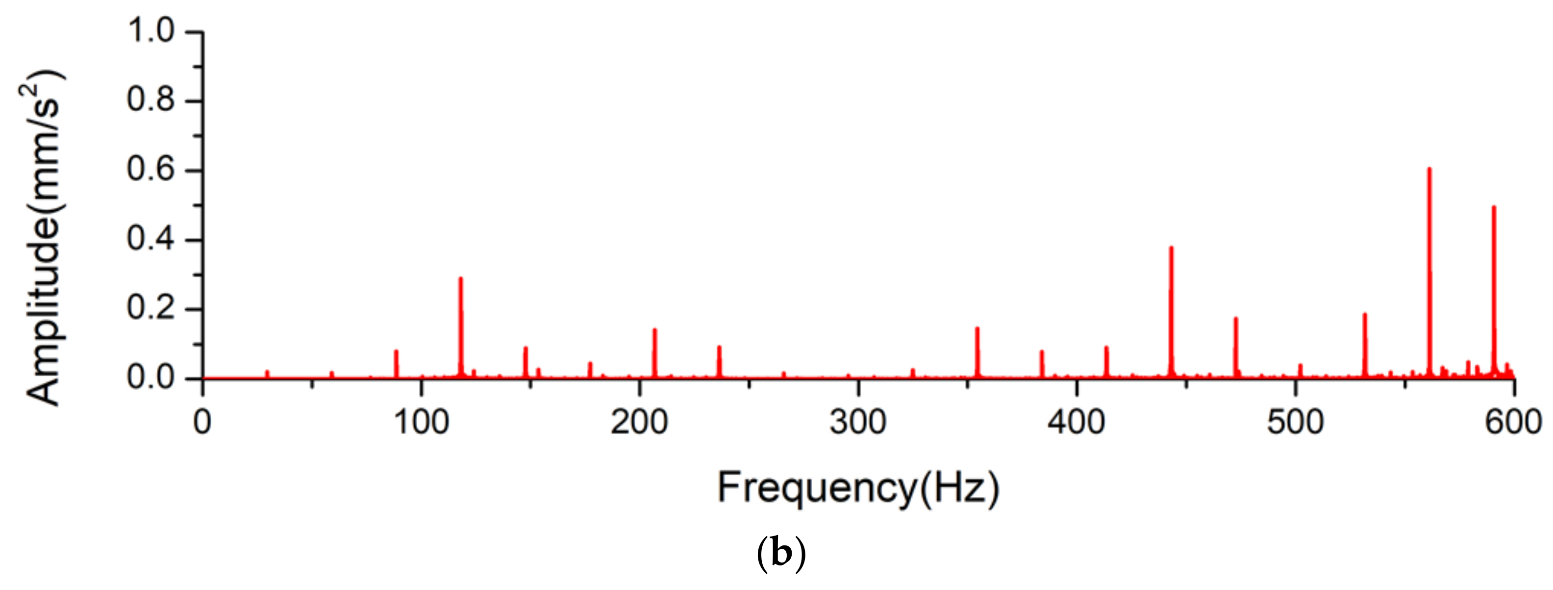
Figure 5 shows the FFT for abnormal states such as breakage of the elastic body and misalignment of the coupling. When comparing the vibration data between normal operation (see
Figure 4a) and breakage of the elastic body, the frequency band showed a similar trend. That is, even though some part of the coupling was broken, the overall vibration trend was similar to the normal state of the coupling. However, in the case of the misalignment of the coupling, the amplitude significantly increased in the overall frequency ranges. In particular, the amplitude near 550 to 600 Hz in the radial direction increased significantly.
5.3. Sealing
The sealing consists of two seal faces, i.e., the stator and screw, which are vertically in the rotation shaft with a cross-contact sealing device. The screw surface rotates with the rotating axis and continues to maintain the sealing of the rotating part with the tension of the spring or the pressure of the fluid. As a result, the sealing plays a role in preventing leakage when the pump is operated. The pump for the ship’s fuel supply works at all times when it operates, supplying high-viscosity and high-temperature refined oil to the engine. A defect, such as wear or damage, may occur. In addition, the heat generated by the temperature of the operating fluid or the operation of the machine can cause the rubber o-ring of the sealing to deteriorate. Finally, it can lead to subsequent failures such as wear and leaks. In the sealing, artificial defects were applied, and data were acquired by mounting it on the equipment.
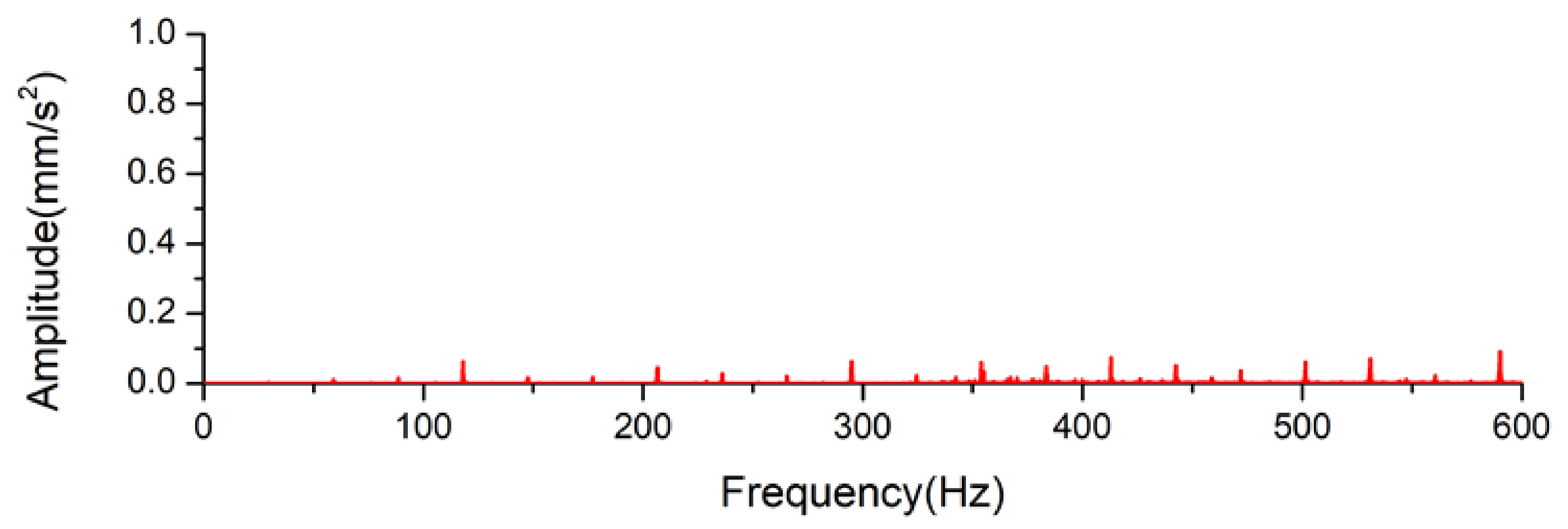
Figure 6 shows the FFT for abnormal status caused by thermal degradation of the sealing. As shown in the figure, it was confirmed that the overall amplitude of the abnormal status increased slightly in the random frequency region of the motor’s radial direction when compared to the normal state.
5.4. Screw
The screw is a major rotating part of the pump drive. The screw rotates the auxiliary axis together, and the fluid is moved by the rotational force. For the smooth flow of fluid, the screw must be smoothly rotated, and for this, it is necessary to maintain the pressure inside the pipe at a constant value and maintain the state of the purified fluid. The pump for the ship’s fuel supply works at all times when it is operated, and when the pump is operated over a long time or in a harsh environment, it faces the pressure environment of unexpected plumbing. This can increase the vibration and noise in the pump. In addition, it may cause friction between the rotor blades by supplying a clean fluid in a state that can increase vibration and noise in the pump. Finally, such problems may accumulate, which can lead to subsequent failures such as corrosion or damage of the screw.
In order to simulate the screw failure, an artificial defect was applied, and real-time state data were acquired.
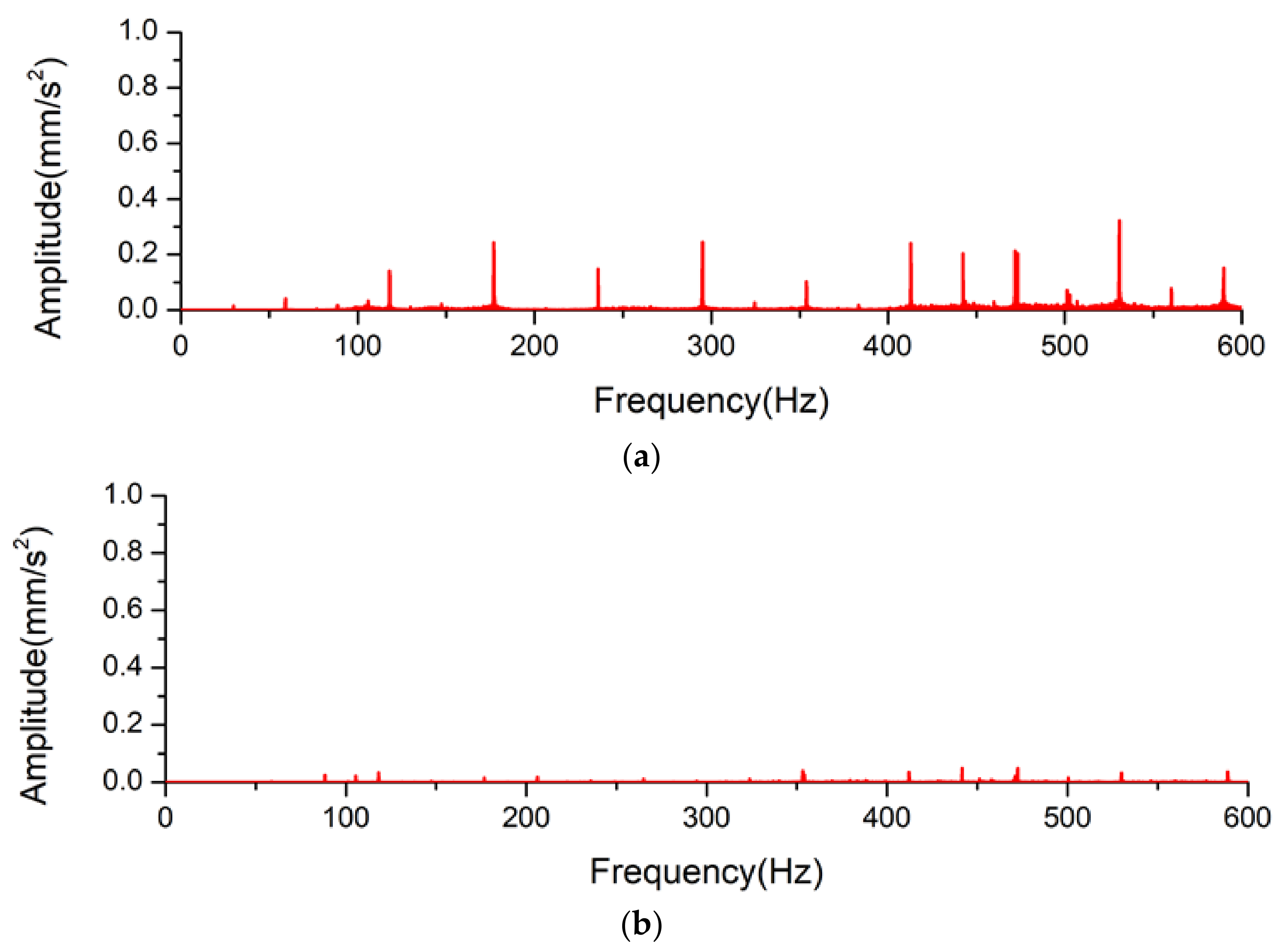
Figure 7 shows the results of the vibration database in the normal state and abnormal state. In the case of the cavitation status shown in
Figure 7a, the amplitude increased significantly in the overall frequency ranges. In particular, the amplitude was concentrated near 400–550 Hz.
Figure 7b shows the results of the vibration data for the wear dependence of the screw. As shown, the vibration occurred in each frequency band, similar to normal data, except for a slight increase in amplitude in the 350–600 Hz frequency range.
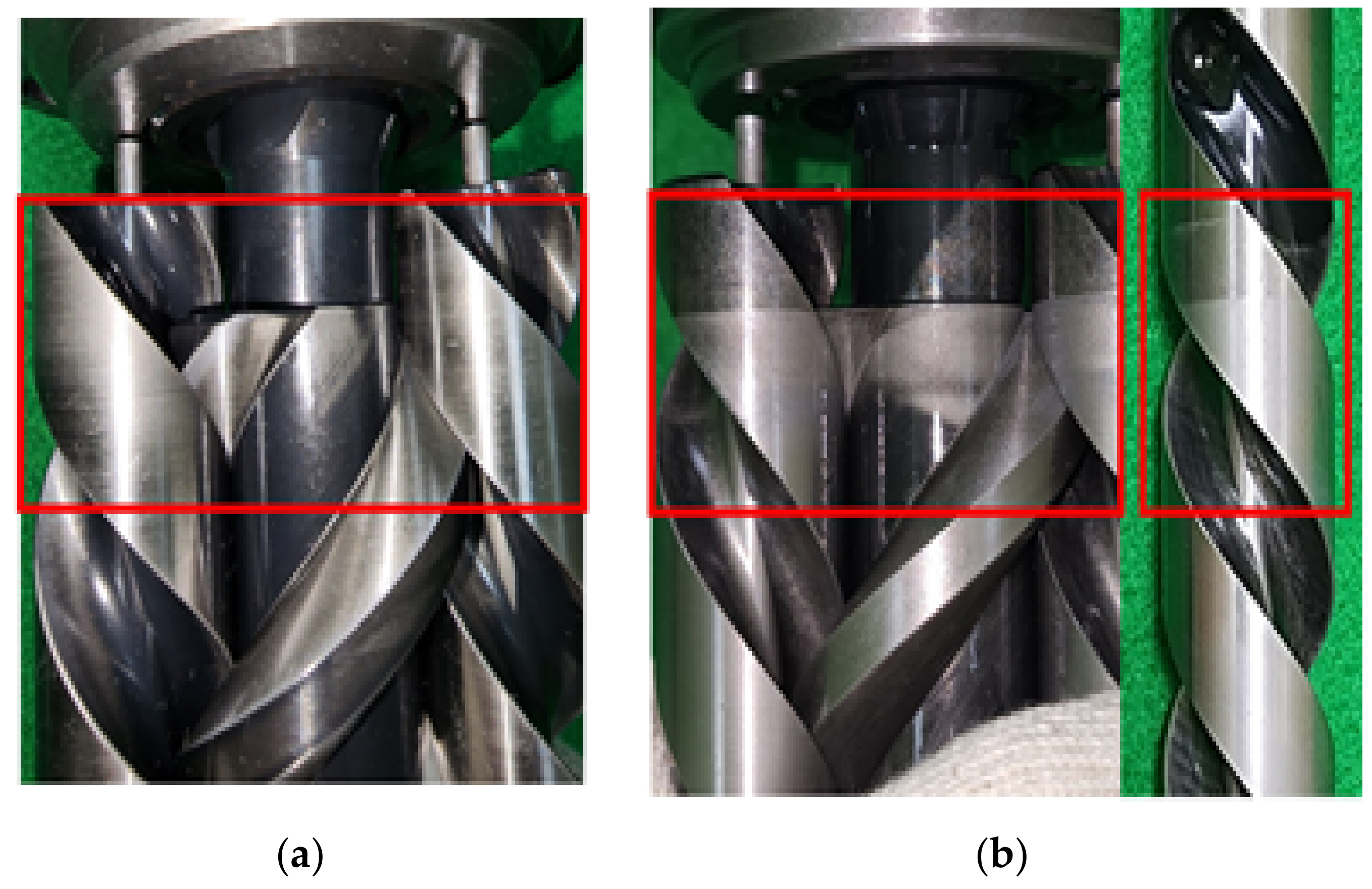
Figure 8 shows the wear characteristics of the rotor prior to and after the test using the contaminated fluid. As shown, the contamination area is distinctive.
5.5. Multi Fault
Most equipment encounters failures that occur within a single component, but multiple failures, i.e., two or more failures caused by vibration and environmental influences, also need to be analyzed. The test was conducted considering the simultaneous occurrence of misalignment and cavitation failure, which are harsh environmental conditions that can occur in pumps used for fuel supply to ships. Even in the case of misalignment of the shaft due to improper installation of the pump and motor, vibration occurs in the coupling part, and fatigue accumulates, leading to fatigue damage of the coupling. Cavitation problems may occur in the face of an unstable pipe pressure environment, which may increase vibration and noise in the pump. Eventually, these problems can accumulate and lead to subsequent failures such as worn out or damaged couplings and screws. In order to simulate complex failures, artificial defects were applied, and real-time status data were acquired.
Figure 9 shows the FFT for a multi-fault (misalignment and cavitation) state of the sealing. As a result, the amplitude of the pump increased, and it was confirmed that the amplitude increased at random frequencies.
6. STFT
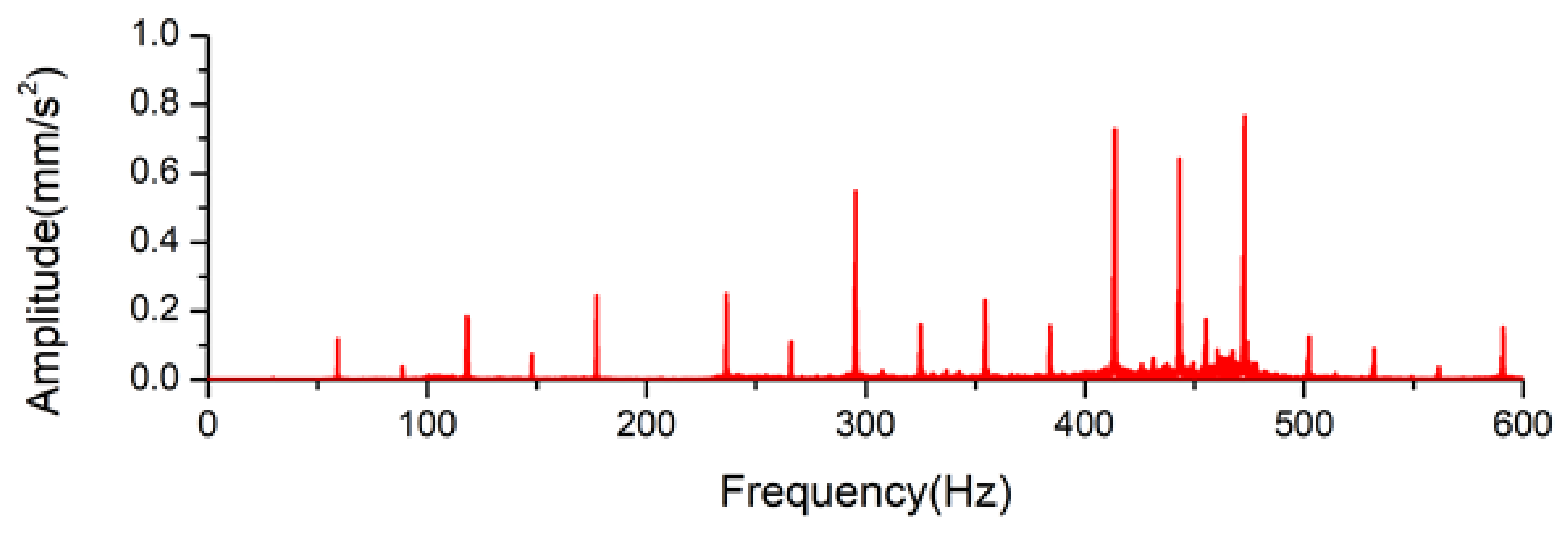
STFT is a technique that analyzes rapidly changing data, such as vibration or noise, in the time–frequency domain. After dividing the data into regular time units, Fourier Transform is applied to each time unit. As the data is divided into units of time and analyzed separately, it is possible to simultaneously analyze the time and frequency domains, and the result can be used as two-dimensional data. STFT was performed considering the time unit for the severe scenario of abnormal conditions, such as the contamination state of the bearing, in various conditions of the coupling, and finally for the cavitation of the screw. Vibration data for 300 s were acquired using the accelerometer. The STFT results of dividing the data at regular time intervals and proceeding with FFT are shown as a result of combining the data over time. The x-axis is the time domain, and the y-axis is the frequency domain, indicating the change in amplitude in the frequency domain over time. In the case of the accelerometer, vibration data were obtained on the pump and motor sides, and through this, both cases were presented.
6.1. Bearing
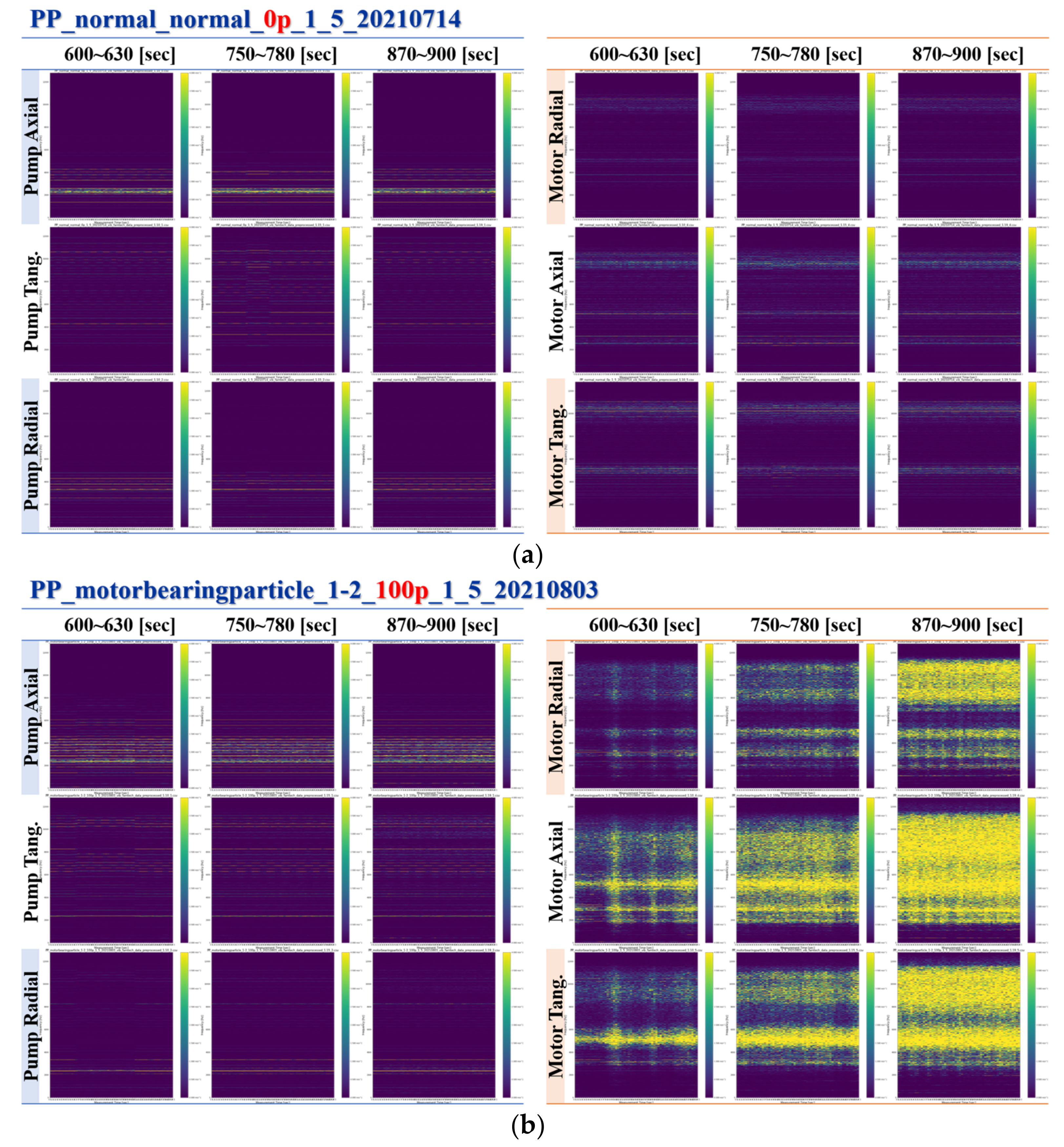
Figure 10 shows the STFT for normal and abnormal states after the contamination. Owing to the contamination of the bearing, the amplitude in all directions near the motor increased significantly, especially within the 2–10 kHz range.
6.2. Coupling
Based on the previous FFT analysis, it was confirmed that significant vibration occurred owing to shaft misalignment. Therefore, the test was performed considering three simulated conditions.
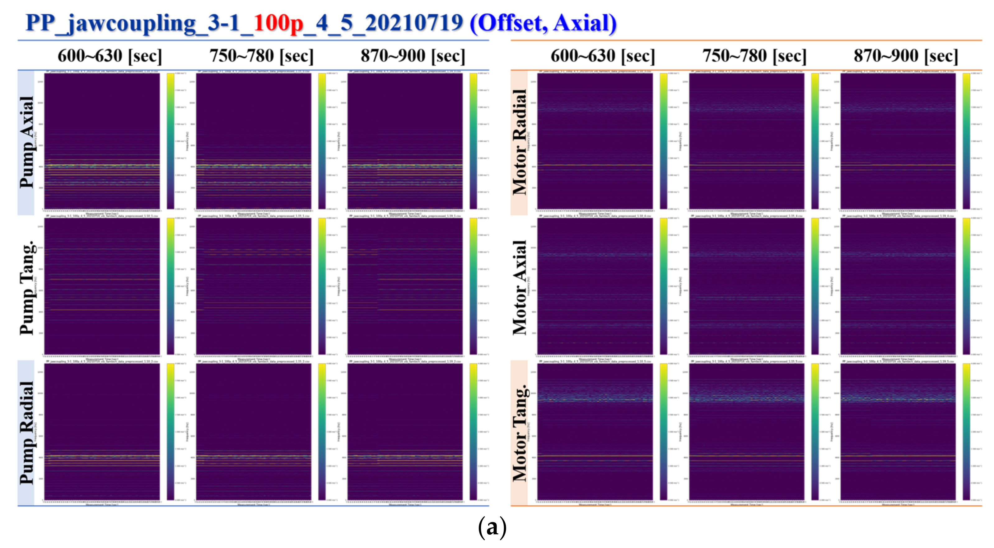
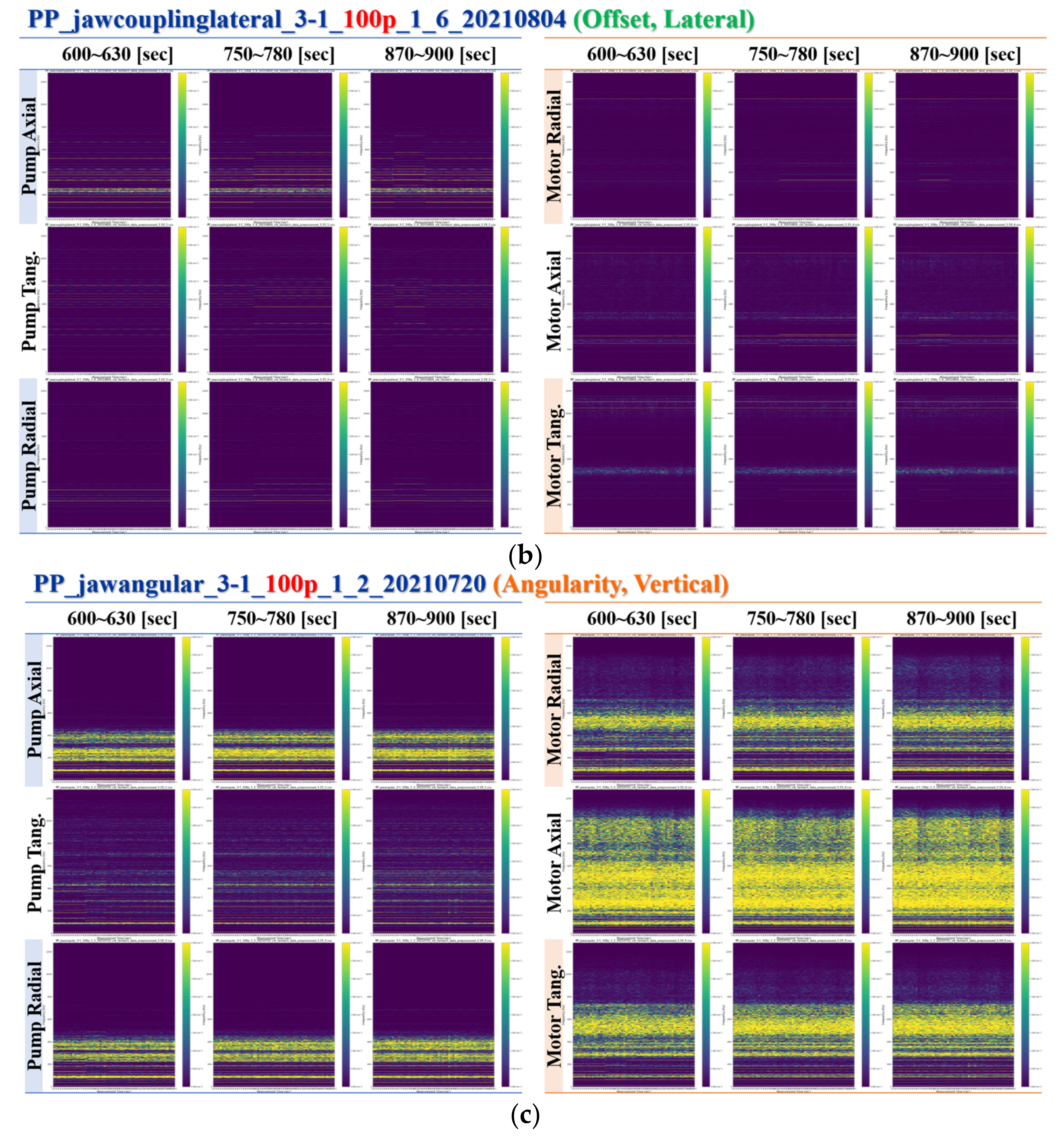
Figure 11 shows the configuration of test scenarios showing three potential misalignments between the pump and motor. When the motor moved to the vertical direction, as shown in
Figure 12a, the vibration occurred in a frequency band similar to the normal data overall, and the amplitude around 2–4 kHz in the pump radial and tangential direction increased slightly. When the motor moved in the horizontal direction, as shown in
Figure 12b, the vibration occurred in each frequency band similar to the normal data as a whole. Finally, when the angular offset was applied in the direction perpendicular to the motor axis, the amplitude increased rapidly around 0–10 kHz, and it was confirmed that the amplitude increased around 0–4 kHz in the radial and axial directions of the pump.
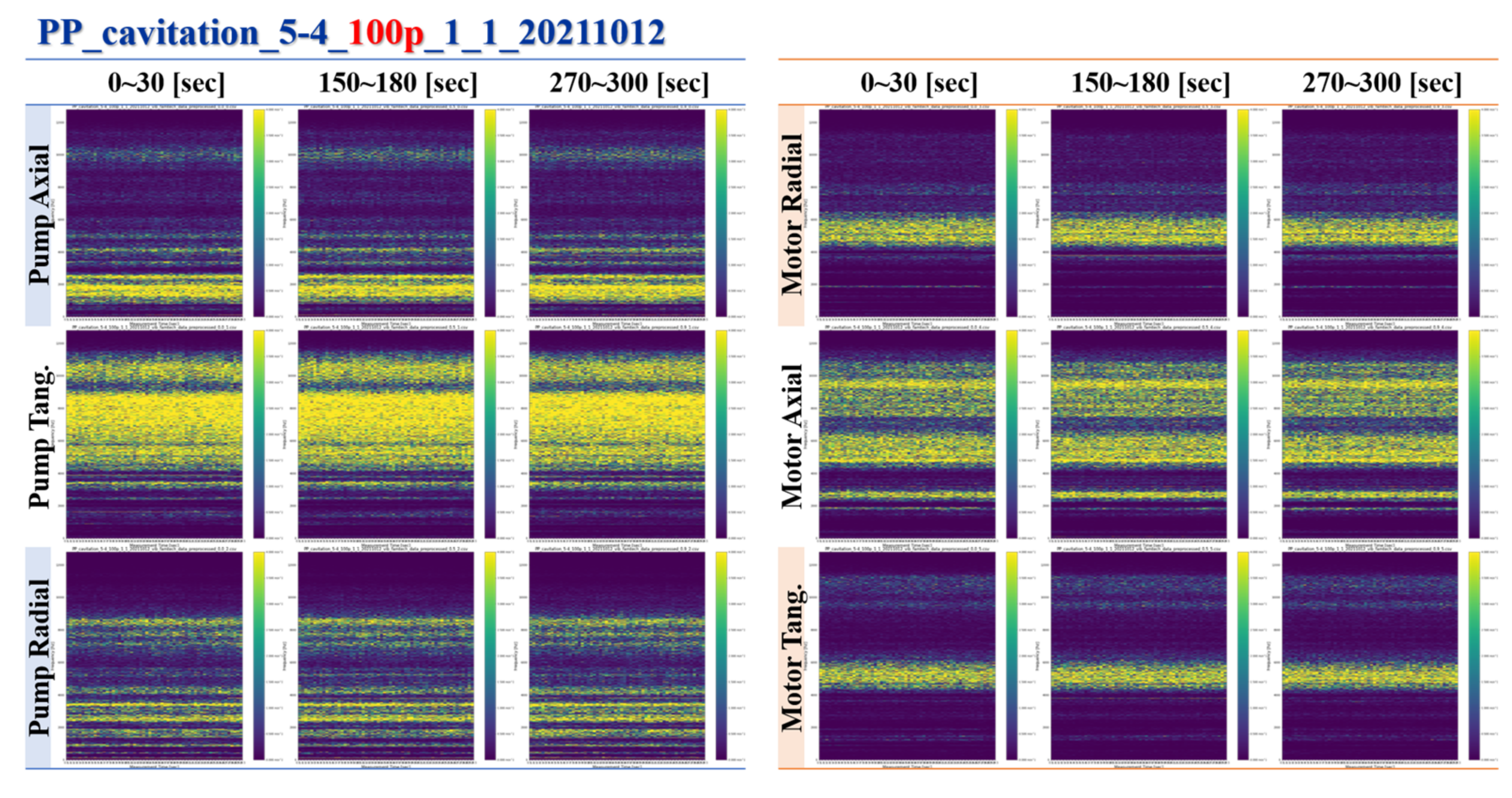
6.3. Screw
Figure 13 shows the STFT for the normal and abnormal state due to the cavitation. Owing to the cavitation of the screw, the amplitude in all directions near the pump and motor increased significantly.
7. Concluding Remarks
In the present study, the main cause and the mechanism of failure for major components were analyzed on a three-axis screw-type pump, which is normally used in the ship’s engine room. The frequency of failure was analyzed using FFT, and more precise results were obtained by performing STFT on the database. More than 200 databases were built with data for the core parts of the oil pump; the data represented operation under both normal and abnormal conditions. The results obtained from this study are summarized below:
- (1)
The failure modes and mechanisms of each part of the pump, such as the bearing, coupling, sealing, and screw, were analyzed using various studies and an accident database.
- (2)
A test bed was established to implement each major failure characteristic and the acquired data considered the pump’s operating conditions.
- (3)
From the results of the FFT for the motor bearing, the contamination condition showed significantly larger amplitude near 400–450 Hz than the case with an absence of lubrication.
- (4)
In the case of the misalignment of the coupling, the amplitude significantly increased in the overall frequency ranges compared with the elastomer breakage case. In particular, the amplitude near 550–600 Hz significantly increased.
- (5)
For the screw of the pump, the amplitude increased significantly in the overall frequency ranges near 400–550 Hz in the case of the cavitation state compared with the wear dependence of the screw.
- (6)
From the results for the sealing, the overall amplitude for the abnormal status increased in the random frequency region. However, most of the amplitude was below 0.1 mm/s2, which is relatively low compared with the other core parts such as the bearing, coupling, and screw.
- (7)
STFT was performed considering the time unit for the extreme scenario of the abnormal condition, such as the contamination state of the bearing, under various conditions of the coupling, and finally for the cavitation of the screw.
Data, such as for the normal and abnormal states of various core parts of the oil pump, were collected in multiple ways and are still being collected. The STFT can analyze frequency characteristics effectively, but we need to efficiently analyze abnormal signals. Therefore, as a follow-up study, research techniques will be developed to analyze the abnormal signals much more effectively using STFT. In addition, we plan to establish a dynamic database for failure conditions and continue to prove reliability based on this database. The data verified through this study are expected to serve as the basis for developing failure diagnosis and prediction algorithm models to improve ship integrity management technology.


 ,
, 


