Article

Vibration Performance of Steel Fiber Concrete Tunnel Lining by Adjacent Tunnel Blasting Construction

1
School of Civil Engineering, Chongqing Jiaotong University, Chongqing 400074, China
2
School of Urban Construction Engineering, Chongqing Technology and Business Institute, Chongqing 400052, China
3
Chongqing Municipal Key Laboratory of Geology and Disaster Reduction for Mountainous Highway, Waterway and Transportation, Chongqing Jiaotong University, Chongqing 400074, China
4
School of Civil Engineering and Architecture, Chongqing University of Science & Technology, Chongqing 401331, China
5
The 5th Engineering Ltd. of China Railway Construction Corporation 11 Group, Chongqing 400037, China
*
Author to whom correspondence should be addressed.
Appl. Sci. 2023, 13(7), 4201; https://doi.org/10.3390/app13074201
Submission received: 29 January 2023 / Revised: 20 March 2023 / Accepted: 24 March 2023 / Published: 26 March 2023

Abstract

:
When constructing tunnels in mountainous areas, the drilling and blasting method is the most commonly used because of its economy. Ordinary reinforced concrete itself has defects such as poor crack resistance and brittleness. Therefore, when using the drilling and blasting method for ordinary reinforced concrete double-line tunnels, vibration phenomena will occur and cause cracks in the first-line tunnels, which will have adverse effects on the durability and safety of the tunnel. As a response, scholars have proposed the use of steel fiber-reinforced concrete as tunnel lining. In this paper, the LS-DYNA software is used to establish three models of plain concrete, ordinary concrete, and steel fiber-reinforced concrete, and numerical analysis is conducted with different amounts of explosives. The results show that the steel fiber-reinforced concrete tunnel lining has better performance than the other two concretes in tunnel construction.

1. Introduction

Western China is experiencing an increase in railways, highways and other transportation facilities with the adoption of western development policies. Due to the geographical characteristics of the region, the construction of these facilities will inevitably lead to cross tunnels and parallel tunnels with small clearance and other situations. At present, the most widely used is the New Austrian Tunneling Method (NATM), in which blasting construction will inevitably affect the safety and usability of the advance tunnel. Therefore, the research team analyzed the impact of blasting shock and vibration on the adjacent steel fiber tunnel lining through numerical simulation [1,2,3].
Remarkable results have been made on the blasting construction of nearby tunnels. Qi and Liu [4] studied the mechanical properties of fiber-reinforced concrete shield segments, and obtained that the bending, yield, and ultimate bending moment of the segments with fiber are significantly higher than those of ordinary segments under the same reinforcement ratio. Xu et al. [5] simulated the pure steel fiber segment of a hard rock tunnel through FLAC3D, and conducted field tests in Qingdao Metro Line 1. The result showed that the pure steel fiber concrete segment has better crack resistance, and it is feasible to replace steel. He et al. [6] also adopted FLAC3D in Hangzhou Metro Line 5 to analyze the blasting vibration in the excavation of small clear-distance tunnels to the support of the adjacent tunnel in an urban area. In the Aiminshan Tunnel in Dandong, Liaoning Province, Wang et al. [7] used ANSYS to analyze the seismic impact of blasting excavation on the surface and concluded that the cavity effect caused the excavated surface to vibrate more quickly than the unexcavated surface. Zhang et al. [8] adopted field monitoring and software simulation to study the influence of blasting from the rear tunnel on the structural optimization of the secondary lining of the advance tunnel under soft and broken surrounding rocks in the Xinmin Tunnel. Pan et al. [9] used the numerical model to analyze the construction sequence, the time and method of secondary lining in three parallel tunnels with the middle one constructed first, as well as the impact of blasting the tunnels on both sides of the secondary lining of the middle tunnel in the parallel section of the Sunjiawan Tunnel 1 on the Yongzhou Highway and the Niupilingxia Tunnel on the Yongzhou Railway. Wang et al. [10] studied the dynamic response characteristics of the blasting from the adjacent tunnel on the lining structure at the intersection of the first tunnel in the intersection of the Wuwu high-speed railway tunnel and Xizengshan highway tunnel, and concluded that the arch shoulder and crown of the first tunnel are sensitive to blasting stress, and that close attention should be paid during construction. Wu and Ren [11] used ABAQUS to study the stress response of the first tunnel to the blasting of the rear tunnel in the small clear-distance tunnel, and concluded that the inner arch waist and the foot are most affected and deserve further observation. Guo et al. [12] used LS-DYNA and field tests to study the rule of tunnel failure under the blasting load of adjacent tunnels with different spacings, and obtained the form of the failure and the location of the crack. Mao [13] observed the on-site expansion project of the Fuzhou Mawei Tunnel, and studied the attenuation characteristics of the velocity of the vibration energy under multiple cavities. Chen et al. [14] tested on site the in situ expansion project of the Jinjishan Tunnel on the Second Ring Road in Fuzhou, Fujian Province, and concluded that in the blasting construction, the number of explosives used in the cut hole should be appropriately reduced, and increased in the wide slot hole and auxiliary hole. Ding et al. [15] studied the influence of blasting construction on the 33-story frame structure at Exit A of the Xizhen of Qingdao Metro Line 1, and the result is a reference for the protection of high-rise buildings during urban blasting construction. By employing on-site monitoring, Wu et al. [16] investigated the law of vibration in the unique stratum of the upper soft and lower hard, and confirmed the viability of numerical simulation for engineering blasting. Bao et al. [17] studied the impact of blasting on surrounding rocks in the seepage area of the tunnel ahead through on-site monitoring and numerical simulation, and concluded that the arch waist has the maximum vibration velocity, the excavation of the lower bench has greater destructive force than that of the upper bench under the same spacing, and the minimum safety clearance is D (D is the tunnel span). Guan et al. [18] first summarized the development stage of failure evolution based on the field data, then used LS-DYNA to determine the vibration response and failure mode of the temporary middle wall under different explosive amounts and blasting distances. Zhou et al. [19] studied the impact of blasting in the adjacent tunnel on the initial support and lining of the ultra-small distance tunnel based on the Jiuwuji tunnel blasting project in Guizhou Province, and the result showed that the main frequency distribution of the initial support and lining is very wide and the vibration is diverse, within 200 Hz. Zhang et al. [20], by monitoring particles on the lining of the tunnel, studied the influence of blasting on the tunnel, and concluded that the peak particle velocity generated is always caused by the cutting hole blasting. Wu et al. [21] through field monitoring and simulation by FLAC3D, analyzed the influence of blasting of a new tunnel on the operating tunnel, and concluded that the vibration velocity of the arch in the blasting surface of the existing tunnel is larger, and the blasting will have an impact on a moving train. Fang et al. [22] carried out research on the Qiandouquan Tunnel project by adopting single-layer and double-layer p blasting schemes, and found that the double-layer presplitting blasting can reduce the vibration speed better by comparison. By tracking and analyzing the field particle vibration velocity through numerical simulation in the Nanjing Metro’s ultra-small clear-distance tunnel project, Zhu et al. [23] discovered that the vibration velocity of the side wall of the tunnel is greater than that of the arch foot. Moreover, the closer the blasting point, the greater the vibration velocity. Cui et al. [24] studied the improvement of the energy performance of subway tunnels using steel fiber-reinforced concrete lining to enhance shallow geothermal energy. They found that the thermal conductivity of the steel fiber-reinforced concrete lining is better than that of ordinary concrete lining with advantages in heat exchange and cooling operation. Hosseini et al. [25] studied the use of glass fiber-reinforced polymer (GFRP) to reinforce high-strength concrete lining segments, and found that the segments with GFRP have bending and shear strength, but with little effect on the lining segments after cracking.
In summary, there is little research on the impact of small-spacing tunnel blasting construction on adjacent steel fiber tunnel linings. Some scholars have found that steel fiber-reinforced concrete lining has significant improvements in bending moment, yield moment, and ultimate moment compared with steel-reinforced concrete lining. The structural vibration velocity from blasting can be used as an indicator of the strength of the blasting vibration effect. The peak vibration velocity during blasting construction differs in tunnels, but the closer the blasting point, the greater the vibration velocity.
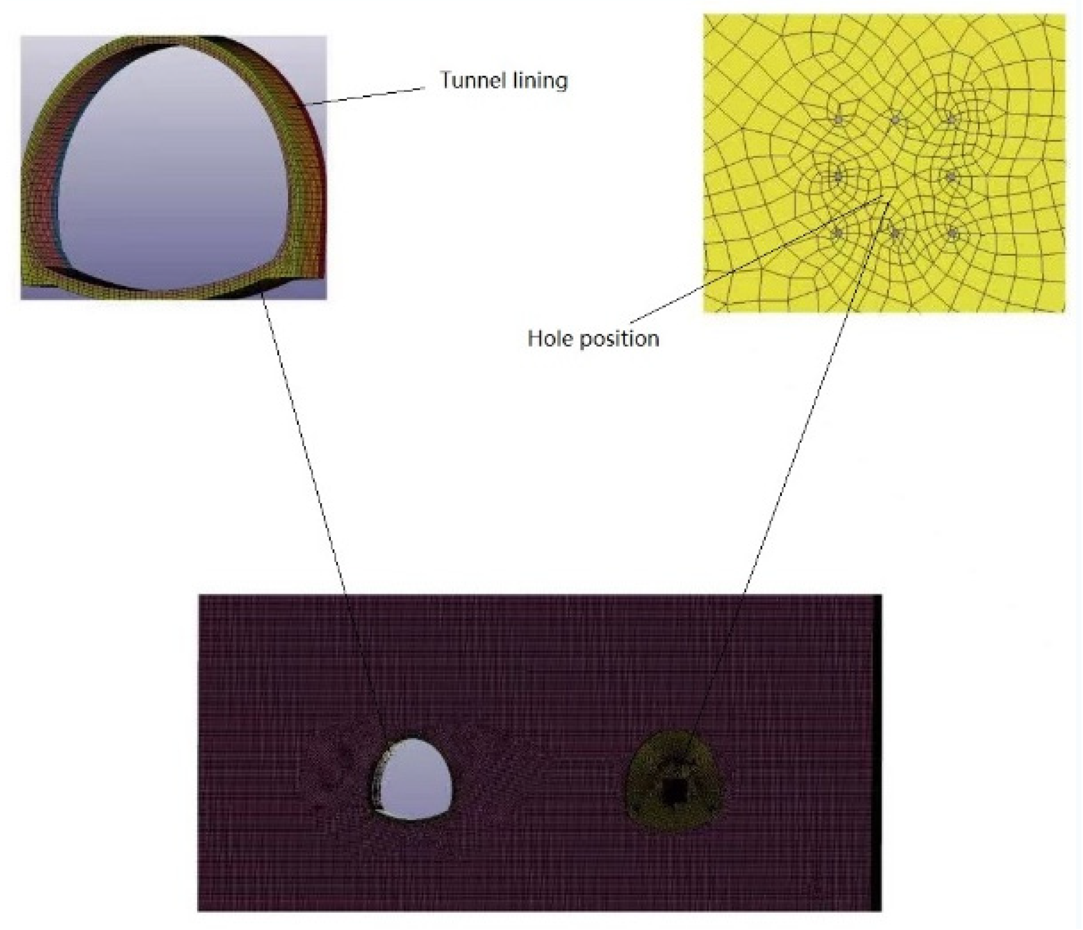
This paper uses LS-DYNA to establish three tunnel-lining models and simulates the impact of blasting construction on adjacent tunnel linings with different explosive amounts. The three types of tunnel linings are plain, ordinary reinforced, and steel fiber-reinforced concrete, and the explosive amounts are 14.4 kg, 18 kg, 21.6 kg, 25.2 kg, and 28.8 kg. The vibration response law of the adjacent tunnels in the three lining models under different explosive amounts is analyzed. Hopefully, the research results will provide a reference for future engineering design and tunnel construction.

2. Numerical Simulation

2.1. Tunnel Geometry

The geometric dimensions of double-track tunnels are the same: the net width of the building is 11.2 m, and the height limit is 7.94 m. The clear width of the inner contour is 9.48 m, and the clear height is 6.59 m. The excavation depth is 0.88 m. See Figure 1 for detailed layout information.

2.2. Establishment of Calculation Model

2.2.1. Constitutive Model of Surrounding Rock

The follow-up hardening material model is adopted for the surrounding rock, which is defined as *MAT_PLASTIC_KINEMATIC. This model describes the strengthening effect and strain rate change effect of materials, with the elastoplastic properties of the rock media considered. The yield condition is [26]:
ϕ = 1 2 ξ i j 2 σ y 2 3 = 0
where:
ξ i j = s i j a i j
σ y = [ 1 + ( ε ˙ C ) 1 p ] ( σ 0 + β E p ε e f f p )
where: s i j is the Cauchy stress tensor; P and C are input constants; σ 0 and β are initial yield stress and hardening parameter, respectively; ε ˙ is the strain rate; E p is the plastic hardening model, where E p = E r E E E r , E is the elastic modulus, E r is tangent modulus; and ε e f f p is the effective plastic strain.
The parameters of the surrounding rock are consistent with those tested, as shown in Table 1.

2.2.2. Lining Strength Parameters

The strength parameters of the model are C30 concrete. When establishing the reinforced concrete lining model, plain and reinforced concrete are modeled, respectively. The parameters are shown in Table 2, Table 3 and Table 4.

2.2.3. Explosive Material Model and Equation of State

Under detonation conditions, high-temperature and high-pressure gases will be generated in the structures. The composition of explosive products and various thermodynamic parameters at certain times are required to build the required equation of state through the mixing rule, but these required parameters are difficult to measure experimentally at present. Therefore, the semi-empirical equation of state (JWL) determined by experimental methods is used to describe the relationship between pressure P, volume V and temperature T. The JWL equation is shown in the following Formula [26].
p = A ( 1 ω R 1 V ) e R 1 V + B ( 1 ω R 2 V ) e R 2 V + ω E V
Its isentropic equation is:
P s = A exp ( R 1 V ) + B exp ( R 2 V ) + C V ( ω + 1 )
e s = A R 1 exp ( R 1 V ) + B R 2 exp ( R 2 V ) + C ω V ω
where P is the pressure of the detonation product, V is the relative volume V = v ˜ / v ˜ 0 , E is the initial internal energy of explosive per unit volume, A, B, R1, R2, ω are parameters of the JWL equation; and the subscript s represents an isentropic process. The specific values of each parameter of the JWL equation are shown in Table 5.

2.2.4. Airy Material Model and Equation of State

The NULL model and the LINEAR_POLYNOMIAL equation are adopted, and the equation of state is:
P = C 0 + C 1 μ + C 2 μ 2 + C 3 μ 3 + ( C 4 + C 5 μ + C 6 μ 2 ) E
μ = 1 V 1
where P is detonation pressure; E is internal energy per unit volume; and V is the relative volume. For the air model, the parameters of the polynomial equation of state are:
C 0 = C 1 = C 2 = C 3 = C 6 = 0 C 4 = C 5 = 0.4
The air density is 1.225 kg/m3, and the initial relative volume V 0 is 1.0.

2.3. Calculation Model

LS-DYNA is adopted for dynamic numerical simulation and calculation, and single-hole blasting is also adopted in consistency with the experiment [27,28,29]. The blasting point is located in the center of the tunnel face for simulation. Since the boundary size is small, in order to reduce the boundary effect and the impact caused by reflected waves, and ensure the accuracy of the calculation, the keyword *BOUNDARY_NON_REFLECTING is used to apply a non-reflective boundary at the lateral boundary of the calculation area to simulate the semi-infinite boundary of the site. The top surface is a free boundary, and the ground and all sides are normal constraints. Figure 2 depicts the 3D finite element model.

3. Calculation Model Analysis

When mining tunnels, the impact on the neighboring tunnel is strongest when the highest amount of explosive is used in the cut hole [30,31,32]. Therefore, analysis is conducted on the impact of the cut hole blasting on the adjacent tunnel. In the three models, the length of each cutting hole is 1 m long, and the explosive amount is 1.8 kg. In each model, 8, 10, 12, 14 and 16 cutting holes are selected, respectively, so the explosive amount is 14.4 kg, 18 kg, 21.6 kg, 25.2 kg and 28.8 kg, accordingly. The monitoring points are at the left line, right arch waist, right wall, and right arch shoulder (lower). The layout of monitoring points is shown in Figure 3.

3.1. Vibration Velocity Analysis of Plain Concrete Tunnel Lining

The analysis at each monitoring point is the comprehensive vibration velocity (the unit of vibration velocity is m/s, and the unit of time is s).
It can be seen from Figure 4, Figure 5 and Figure 6 and Table 6 that: (1) In plain concrete lining, the peak values at each monitoring point increase with the explosive quantity, and the maximum peak values of the right wall, the right arch spandrel and the right arch waist all appear to be at the explosive amount of 28.8 kg, which are 0.00256 m/s, 0.00681 m/s and 0.0023 m/s, respectively, and the peak values all around 0.03 s. (2) Under different explosive quantities, each monitoring point’s vibration law is relatively consistent. No matter how much explosive is used in the monitoring point, the right arch waist has the minimum peak, and the radius of the right arch spandrel is small. The right arch spandrel with the largest peak stress concentration suggests that it is relatively weak during the blasting excavation operation, and has to be watched.

3.2. Vibration Velocity Analysis of Ordinary Concrete Tunnel Lining

The analysis at each monitoring point is the comprehensive vibration velocity (the unit of vibration velocity is m/s, and the unit of time is s).
It can be seen from Figure 7, Figure 8 and Figure 9 and Table 7 that: (1) In ordinary reinforced concrete lining, the peak values at each monitoring point increase with the amount of explosives, and the maximum peak values of the right wall, the right arch spandrel and right arch waist are at the explosive amount of 28.8 kg, which are 0.00231 m/s, 0.00594 m/s and 0.00182 m/s, respectively, and the peak values all appear near 0.03 s. (2) The vibration law of each monitoring point is relatively consistent under different explosive quantities. No matter how much explosive is used in the monitoring point, the minimum peak value is at the right arch waist; the radius of the right arch spandrel is small, and the maximum peak value of the stress concentration is at the right arch spandrel, indicating that the right arch shoulder is relatively weak during the blasting excavation and needs to be observed. (3) Compared with plain concrete, the vibration velocity at the right wall, the right spandrel and right arch waist is generally larger as a result of good integrity from the addition of reinforcement.

3.3. Vibration Velocity Analysis of Steel Fiber-Reinforced Concrete Tunnel Lining

The analysis at each monitoring point is the comprehensive vibration velocity (the unit of vibration velocity is m/s, and the unit of time is s).
It can be observed from Figure 10, Figure 11 and Figure 12 and Table 8 that: (1) In the ordinary reinforced concrete lining, the peak values at each monitoring point increase with the explosive quantity. The maximum peak values of the right wall and the right arch spandrel occur at the explosive amount of 28.8 kg, which are 0.00301 m/s and 0.00832 m/s, respectively. The maximum peak of the right arch waist occur at the explosive amount of 21.6 kg, which is 0.00232 m/s, and the peak values appear at around 0.03 s. (2) The vibration law of the monitoring points on the right wall and the right arch spandrel is relatively consistent and increase all the time under different explosive quantities. However, the vibration speed of the monitoring points on the right arch waist increases first and then falls as the explosive quantity increases, which results from the biggest radius, where the vibration speed is propagated to further sites as the explosive quantity increases.

4. Summary

In this paper, ANSYS/LS-DYNA are used to study the impact of blasting the subsequent tunnel on a steel fiber tunnel lining in advance. By establishing three tunnel models of plain concrete, ordinary reinforced concrete, and steel fiber, and comparing the explosive quantities in the blasting of the subsequent tunnel, the following conclusions are drawn:
  • With plain concrete lining, the peak value of the vibration velocity at each monitoring point appears to be around 0.03 s and increases with the explosive quantity. With the velocity curve basically symmetrical around 0.03 s, it demonstrates consistency in the vibration law.
  • With ordinary reinforced concrete lining, the overall vibration speed is basically the same as that of plain concrete, but increases as a result of the integrity after adding reinforcement.
  • The biggest difference between the steel fiber and the plain concrete tunnel lining is at the right arch waist. The vibration velocity at the right waist increases with the number of explosives, but in the steel fiber tunnel, the vibration velocity at the right arch waist increases and then decreases, with the vibration trend consistent with the other two monitoring points.
  • By comparing the peak values of the vibration velocity at each monitoring point of the three kinds of tunnel lining, it can be concluded that the ordinary reinforced concrete lining at the right wall has the largest vibration velocity; the maximum vibration velocity of the steel fiber tunnel lining occurs at the right arch spandrel, and the gap is large; the maximum vibration velocity of steel fiber tunnel lining is at the right arch waist. Therefore, the integrity of steel fiber tunnel lining is better than the other tunnel linings, with a relatively larger vibration velocity.
  • In conclusion, the steel fiber-reinforced concrete tunnel lining has better integrity compared to plain concrete and reinforced concrete tunnel linings. Therefore, the use of steel fiber-reinforced concrete lining in blasting construction is feasible and can effectively reduce the adverse impact on adjacent tunnels. However, there is a limitation in data on steel fiber-reinforced concrete as tunnel lining in practical engineering.

Author Contributions

Conceptualization, L.-M.W.; formal analysis, Z.-J.W.; investigation, Y.-Z.C. and Y.W.; methodology, L.-M.W.; software, H.-X.F.; supervision, B.Z.; validation, F.G.; writing—original draft, L.-M.W.; writing—review and editing, Y.-Z.C. All authors have read and agreed to the published version of the manuscript.

Funding

This work was sponsored by the Natural Science Foundation of Chongqing, China (Grant No. CSTB2022NSCQ-MSX0975), Key Laboratory of Geological Hazards Mitigation for Mountainous Highway and Waterway, Chongqing Municipal Education Commission Chongqing Jiaotong University (Grant No. kfxm2018-06), Science and Technology Research Program of Chongqing Municipal Education Commission (Grant No. KJQN20210156 and KJZD202204001), Key Scientific Research Projects of Chongqing Technology and Business Institute (Grant No. NDZD2021-03), Steering Science and Technology Plan Project of Civil Engineering Architectural Network of University Chongqing (Grant No. 2022A04, 2022B05, 2022B09, 2023A03, 2023B03, 2023B04 and 2023B05).

Institutional Review Board Statement

Not applicable.

Informed Consent Statement

Not applicable.

Data Availability Statement

Not applicable.

Conflicts of Interest

The authors declare no conflict of interest.

References

  1. Zhang, W.; Kang, S.; Huang, Y.; Liu, X. Behavior of Reinforced Concrete Beams without Stirrups and Strengthened with Basalt Fiber–Reinforced Polymer Sheets. J. Compos. Constr. 2023, 27, 04023007. [Google Scholar] [CrossRef]
  2. Huang, H.; Yao, Y.; Liang, C.; Ye, Y. Experimental study on cyclic performance of steel-hollow core partially encased composite spliced frame beam. Soil Dyn. Earthq. Eng. 2022, 163, 107499. [Google Scholar] [CrossRef]
  3. Huang, H.; Li, M.; Yuan, Y.; Bai, H. Experimental Research on the Seismic Performance of Precast Concrete Frame with Replaceable Artificial Controllable Plastic Hinges. J. Struct. Eng. 2023, 149, 04022222. [Google Scholar] [CrossRef]
  4. Qi, M.S.; Liu, X. A full-scale experimental study on bearing capacity of fiber reinforced concrete segments. Chin. J. Undergr. Space Eng. 2019, 15 (Supp. 1), 55–60. [Google Scholar]
  5. Xu, Z.; Li, D.M.; Wang, B.; Zhan, G.Y.; Zhang, S.J.; Shi, J. Application of pure steel fiber concrete segment in hard rock tunnel. J. Shandong Univ. 2020, 50, 44–49+55. [Google Scholar]
  6. He, J.; Zhu, Y.C.; Shen, M.W.; Yu, F.P. Small clearance blasting in MTR tunnels on adjacent tunnels support vibration response study. Subgrade Eng. 2022, 1, 171–176. [Google Scholar]
  7. Wang, H.J.; Li, Y.W.; Zhao, X.Q.; Wei, H. Numerical simulation of ground vibration effect caused by tunnel blasting excavation. J. Shenyang Univ. Technol. 2022, 44, 461–466. [Google Scholar]
  8. Zhang, W.; Wang, S.F.; Yu, J.B. Study on Optimization of Blasting Scheme for Back Tunnel of Double Arch Tunnel without Pilot Tunnel: Take Xinmin Tunnel as an Example. Tunnel Construction. 2022. Available online: http://kns.cnki.net/kcms/detail/44.1745.u.20220721.1502.004.html (accessed on 29 August 2022).
  9. Pan, W.T.; He, C.; Wu, F.Y.; Xu, Y.J.; Yao, R.J.; Yan, Q.X. Research on the influence of approaching excavation and blasting vibration of small interval three-hole parallel highway tunnels and railway tunnels. Railw. Stand. Des. 2022. [Google Scholar] [CrossRef]
  10. Wang, H.C.; Wang, X.W.; Zhang, Y.B. Analysis of the impact of blasting construction of new tunnels on cross sections of existing tunnels. Sichuan Archit. 2022, 42, 182–184. [Google Scholar]
  11. Wu, W.Q.; Ren, X.F. Study on the Effect of Small Clear Distance Tunnel Blasting Excavation on Adjacent Caverns. Highway 2011, 12, 204–208. [Google Scholar]
  12. Guo, D.M.; Liu, K.; Zhang, W.; Yang, J.; Fan, L.; Xue, L. Research on failure rule and dynamic response of tunnel under adjacent blasting loads of different spacing. J. Beijing Inst. Technol. 2018, 38, 1000–1005. [Google Scholar]
  13. Mao, Z.C. Field test and wavelet analysis of blasting vibration from in-situ tunnel expansion. Eng. Blasting 2022, 28, 103–110. [Google Scholar]
  14. Chen, L.B.; Li, Y.S.; Ling, X.; Liao, C.H. Blast vibration test analysis of in-situ expansion by drill-and-blast method for tunnels with very large cross-sections. Subgrade Eng. 2017, 3, 196–200. [Google Scholar]
  15. Ding, X.; Ji, X.; Gao, S.; Sun, Z.; Wang, H. Vibration response law of high-rise building to tunnel blasting. IOP Conf. Ser. Earth Environ. Sci. 2021, 768, 012165. [Google Scholar] [CrossRef]
  16. Wu, B.; Lan, Y.; Huang, W.; Yang, S. Study on Vibration of Tunnel Blasting Construction in Upper Soft and Lower Hard Ground. IOP Conf. Ser. Earth Environ. Sci. 2019, 242, 062004. [Google Scholar] [CrossRef]
  17. Bao, X.; Zhang, W.; Zhao, S.; Yu, C.; Lü, Y.; Wang, S.; Wu, N. Study on the Influence of the Blasting of Preceding Tunnel on the Pre-Penetration Surrounding Rock in Succeeding Tunnel with Small Clear Distance. Shock Vib. 2022, 2022, 5181154. [Google Scholar] [CrossRef]
  18. Guan, X.; Yang, N.; Zhang, W.; Li, M.; Liu, Z.; Wang, X.; Zhang, S. Vibration response and failure modes analysis of the temporary support structure under blasting excavation of tunnels. Eng. Fail. Anal. 2022, 136, 106188. [Google Scholar] [CrossRef]
  19. Zhou, X.; Zhang, X.; Feng, H.; Zhang, S.; Yang, J.; Mu, J.; Hu, T. Study on Dominant Frequency Attenuation of Blasting Vibration for Ultra-Small-Spacing Tunnel. Appl. Sci. 2022, 12, 1058. [Google Scholar] [CrossRef]
  20. Zhang, Q.; Zhang, Z.; Wu, C.; Yang, J.; Wang, Z. Characteristics of Vibration Waves Measured in Concrete Lining of Excavated Tunnel during Blasting in Adjacent Tunnel. Coatings 2022, 12, 954. [Google Scholar] [CrossRef]
  21. Wu, B.; Lan, Y.B.; Yang, J.X.; Han, Y.L.; Pang, X.Y. Influence of new tunnel blasting on vibration characteristics of adjacent existing tunnel. China Saf. Sci. J. 2019, 29, 89–95. [Google Scholar]
  22. Fang, N.; Yang, C.H.; Sun, J.P.; Ma, Y.Q.; Miao, Y.S. Study on vibration of single double layer pre-cracking blasting in ultra-small clearances tunnels. Railw. Eng. 2015, 7, 58–60. [Google Scholar]
  23. Zhu, Z.G.; Sun, M.L.; Zhu, Y.Q.; Sun, X.L. Field monitoring on blasting vibration and dynamic response of ultra-small spacing tunnels. Rock Soil Mech. 2012, 33, 3747–3752. [Google Scholar]
  24. Cui, H.; Li, Y.; Bao, X.; Tang, W.; Wang, S.; Chen, X. Thermal performance and parameter study of steel fiber-reinforced concrete segment lining in energy subway tunnels. Tunn. Undergr. Space Technol. 2022, 128, 104647. [Google Scholar] [CrossRef]
  25. Hosseini, S.M.; Mousa, S.; Mohamed, H.M.; Eslami, A.; Benmokrane, B. Experimental and Analytical Study on Precast High-Strength Concrete Tunnel Lining Segments Reinforced with GFRP Bars. J. Compos. Constr. 2022, 26, 04022062. [Google Scholar] [CrossRef]
  26. Bai, J.Z. LS-DYNA3D Theoretical Basis and Example Analysis; Science Press: Beijing, China, 2005. [Google Scholar]
  27. Huang, Y.; Huang, J.; Zhang, W.; Liu, X. Experimental and numerical study of hooked-end steel fiber-reinforced concrete based on the meso- and macro-models. Compos. Struct. 2023, 309, 116750. [Google Scholar] [CrossRef]
  28. Dong, Z.; Quan, W.; Ma, X.; Li, X.; Zhou, J. Asymptotic homogenization of effective thermal-elastic properties of concrete con-sidering its three-dimensional mesostructure. Comput. Struct. 2023, 279, 106970. [Google Scholar] [CrossRef]
  29. Liu, H.; Yue, Y.; Liu, C.; Spencer, B.; Cui, J. Automatic recognition and localization of underground pipelines in GPR B-scans using a deep learning model. Tunn. Undergr. Space Technol. 2023, 134, 104861. [Google Scholar] [CrossRef]
  30. Zhang, Z.; Liang, G.; Niu, Q.; Wang, F.; Chen, J.; Zhao, B.; Ke, L. A Wiener degradation process with drift-based approach of determining target reliability index of concrete structures. Qual. Reliab. Eng. Int. 2022, 38, 3710–3725. [Google Scholar] [CrossRef]
  31. Wu, M.; Ba, Z.; Liang, J. A procedure for 3D simulation of seismic wave propagation considering source-path-site effects: Theory, verification and application. Earthq. Eng. Struct. Dyn. 2022, 51, 2925–2955. [Google Scholar] [CrossRef]
  32. Lu, Z.-Q.; Liu, W.-H.; Ding, H.; Chen, L.-Q. Energy Transfer of an Axially Loaded Beam with a Parallel-Coupled Nonlinear Vibration Isolator. J. Vib. Acoust. 2022, 144, 4054324. [Google Scholar] [CrossRef]
Figure 1. Layout of tunnel dimensions (unit: cm).
Applsci 13 04201 g001
Figure 2. Three-dimensional finite element model.
Applsci 13 04201 g002
Figure 3. Layout of monitoring points on the left line.
Applsci 13 04201 g003
Figure 4. Vibrational velocity curve of the right wall of the plain concrete tunnel.
Applsci 13 04201 g004aApplsci 13 04201 g004b
Figure 5. Vibrational velocity curve of the right arch shoulder of the plain concrete tunnel.
Applsci 13 04201 g005aApplsci 13 04201 g005b
Figure 6. Vibrational velocity curve of the right arch waist of the plain concrete tunnel.
Applsci 13 04201 g006aApplsci 13 04201 g006b
Figure 7. Reinforced concrete tunnel right wall vibration speed curve.
Applsci 13 04201 g007
Figure 8. Vibration velocity curve of right arch shoulder of reinforced concrete tunnel.
Applsci 13 04201 g008
Figure 9. Reinforced concrete tunnel right arch waist vibration speed curve.
Applsci 13 04201 g009
Figure 10. Steel fiber concrete tunnel right wall vibration speed curve.
Applsci 13 04201 g010aApplsci 13 04201 g010b
Figure 11. Vibration velocity curve of right arch shoulder of steel fiber concrete tunnel.
Applsci 13 04201 g011aApplsci 13 04201 g011b
Figure 12. Steel fiber concrete tunnel right arch waist vibration speed curve.
Applsci 13 04201 g012aApplsci 13 04201 g012b
Table 1. Material parameters of tunnel surrounding rock.
MaterialUniaxial Compressive Strength (MPa)Elasticity Modulus Ec (MPa)Poisson’s RatioDensity ρ kg/m3
Tunnel surrounding rock22.246840.192450
Table 2. Strength parameters of plain concrete lining.
MaterialElasticity Modulus Ec (MPa)Poisson’s RatioDensity ρ kg/m3
Concrete lining30,0000.22360
Table 3. Strength parameters of reinforced concrete lining.
MaterialElasticity Modulus Ec (MPa)Poisson’s RatioDensity ρ kg/m3
Concrete lining30,0000.22360 kg/m3
Rebar210,0000.31.58 kg/m
Table 4. Strength parameters of steel fiber-reinforced concrete lining.
MaterialElasticity Modulus Ec (MPa)Poisson’s RatioDensity ρ kg/m3
Steel fiber + concrete34,9000.152510
Table 5. Parameters of the JWL equation of state.
ExplosiveDetonation Velocity/ms−1A/GPaB/GPaR1R2ωE/GJm−3
TNT69303.7373.7474.150.950.356.0
The parameters above are based on TNT explosive.
Table 6. Peak particle velocity and location with different explosive quantities.
LocationQuantity of Explosive (kg)14.41821.625.228.8
Right side wallPeak (m/s)0.001960.002150.002180.002240.00256
Right spandrelPeak (m/s)0.005430.005630.005670.005970.00681
Right hancePeak (m/s)0.001160.00180.00190.00200.0023
Table 7. Peak particle velocity and location with different explosive quantities.
LocationQuantity of Explosive (kg)14.41821.625.228.8
Right side wallPeak (m/s)0.002460.002740.002450.0024440.00231
Right spandrelPeak (m/s)0.004050.004880.005030.005370.00594
Right arch waistPeak (m/s)0.001520.001770.002130.002000.00182
Table 8. Peak particle velocity and position of vibration velocity with the same explosive quantity.
LocationQuantity of Explosive (kg)14.41821.625.228.8
Right side wallPeak (m/s)0.001950.001980.002120.002220.00301
Right spandrelPeak (m/s)0.006670.006710.006950.007310.00832
Right arch waistPeak (m/s)0.002200.001790.002320.001860.00177
Disclaimer/Publisher’s Note: The statements, opinions and data contained in all publications are solely those of the individual author(s) and contributor(s) and not of MDPI and/or the editor(s). MDPI and/or the editor(s) disclaim responsibility for any injury to people or property resulting from any ideas, methods, instructions or products referred to in the content.

