Abstract
The safety assessment of existing structures in areas with a relevant seismic hazard is one of the major topics for engineers since many existing reinforced concrete structures have been realized disregarding seismic design with minimal details with respect to present practice. In this context, seismic assessment is a primary issue in order to identify the best retrofitting solution with the aim of enhancing the efficiency of existing buildings. In recent years, with the aim to enhance the seismic behavior of reinforced concrete (RC) structures (with particular care to existing ones), the system of seismic isolation adopting friction pendulum (FPS) devices proved to be among the most diffuse and effective solutions. The purpose of this paper is to explore the effectiveness of the refurbishment using FPS with single concavity devices on the performance of one irregular existing RC building placed in a highly seismic area of central Italy. First, the geometric and material characteristics of the building have been determined within the approach based on the “knowledge levels”. Second, a suitable numerical model based on a fiber-modeling approach has been established using SAP2000, including relevant mechanical non-linearities. Then, a set of 21 natural seismic inputs, inclusive of 3 accelerations over vertical and horizontal directions, was adopted with the aim of performing non-linear (NL) dynamic simulations. The NL dynamic simulations have been performed considering the structural system, both inclusive and not inclusive of the FPS isolator devices. The influence of the actual distribution of infill masonry panels on the overall behavior of the structure has also been evaluated in both of the cases mentioned above. Finally, the outcomes deriving from the NL dynamic simulations were helpful in assessing the advantages of the intervention of retrofitting to improve the seismic performance of the building, highlighting the influence of masonry infills.
1. Introduction
The safety assessment of existing structures placed in areas with a relevant seismic hazard has been one of the challenges for engineers over the last few years [1,2]. In particular, during the 1960s and 1970s, many buildings realized in reinforced concrete (RC) were designed with disregard for details in comparison to the current code specifications for seismic areas [3,4]. In fact, a major part of such buildings is conceived for resistance mainly relating to gravity actions, assuming a minor influence of horizontal ones (e.g., seismic events).
In this framework, the assessment of seismic actions is a crucial issue with the aim of identifying proper dispositions to retrofit existing buildings [5,6] with particular care for under-designed structural systems [7]. In recent years, with the aim to enhance the seismic response of RC buildings, the system of seismic isolation adopting friction pendulum (FPS) devices proved to be among the most diffuse and effective solutions [8,9,10,11]. Concerning the application to buildings constituted by RC structural frames, the major benefits relate to achieving a fundamental period not dependent on the mass of the structure placed up to the isolation level (i.e., superstructure). In particular, these devices allow significant energy dissipation capacity during the seismic motion by means of a friction mechanism [12,13]. Moreover, with reference to post-earthquake resilience, the self-recentering capability of the devices can permit fast recovery of building functionality [14]. For the reasons mentioned above, FP devices have been used in many situations in practice to isolate both new buildings and existing ones [15,16,17,18,19]. In this framework, with the purpose of assessing the compliance of the isolation system with respect to the reliability requirements of current design codes, the performance-based seismic design (PBSD) methodology can be adopted, as widely discussed by [12,13].
Contextually, the influence of the masonry infills on the response of RC-framed structures has been widely investigated and recognized for its relevance to overall structural behavior [20,21,22]. However, few studies have been devoted to understanding their interaction with the adoption of seismic isolation systems as FP devices [23,24] with particular reference to buildings characterized by significant irregularities (in-plane, in-elevation, and related to the disposition and configuration of infills).
The purpose of this paper is to explore, in mono- and bi-variate probabilistic terms, the advantages of the refurbishment using FPS with single concavity devices of one irregular RC-framed building placed in a highly seismic area of central Italy, while also investigating the interaction between the masonry infills and the FP isolation system. After the identification of the material and geometric characteristics in line with the “knowledge levels” philosophy [3], a suitable numerical model based on the fiber-modeling approach has been established in the SAP2000 software platform [25]. 3D non-linear dynamic analyses have been performed considering 21 natural ground motions [26,27] with the three accelerometric components to evaluate the performance of the RC building, inclusive and not inclusive of the FP isolators. As mentioned above, the influence of the masonry infills on seismic performance has been investigated [23,24]. In detail, the structure with the base fixed to the foundations (FB) and with the isolation system (BI) has been analyzed with and without the presence of the masonry infills. The local influence due to the interaction between the RC frame and the full and partial infill walls has been examined and accounted for during the definition of the numerical models. The outcomes of the 3D NL dynamic numerical simulations permit assessing the efficiency of the isolator devices to improve the seismic performance of the RC-framed building having both in-plane and in-elevation irregularities. As for engineering demand parameters (EDPs), the non-dimensional interstory drift (i.e., interstory drift index—IDI) and in-plane displacement of the slider of the FPS with respect to the base of the device. The EDPs have been modeled through mono-variate and bi-variate lognormal distributions [12]. Finally, the exceedance probabilities for several values of the EDPs are computed and compared with respect to appropriate thresholds proposed in the scientific literature [28].
2. Strategies to Model Behaviour of FPS and of Masonry Infills in RC Framed Structures
In this section, the model herein adopted to reproduce the behavior of single-concave FP devices as well as the approach adopted to account for the influence of the masonry infills on the seismic response of the RC-framed structure are described.
2.1. Principles of Behviour of FPS with Single Concavity
The FP isolators are devices able to improve the seismic performance of RC-framed buildings in areas with high seismicity [17,19,26]. Particularly, the FP devices allow for disconnecting the superstructure from the foundation level and are able to accommodate most of the seismic demand for displacement. In addition, these devices are able to provide high energy dissipation through friction developed between the sliding surfaces [12]. These devices are realized through a slider device that can move on a surface having a concave shape, which is characterized by a specific curvature radius R [29] and friction coefficient [30,31]. The adoption of single-concave FP leads to the main advantage of having the first natural period of the base-isolated structure Tis dependent only on the curvature radius R [12]. The above-mentioned dependence can be expressed as follows:
where the acceleation of gravity is denoted by g.
The basic response in terms of the dynamic equilibrium of the FPS device is represented in Figure 1a by means of the free-body diagram of the slider and the related equilibrium equation with respect to translation along the tangent direction to the sliding surface. After mathematical manipulation of the equilibrium equation shown in Figure 1a and assuming that the discrepancy between the normal direction to the sliding surface and the vertical one is negligible according to [11,12] (i.e., tangent direction to the sliding surface coincides, reasonably, with the horizontal one), the restoring force of the FP bearing device can be determined as follows:
where M is the mass of the portion of structure pertaining to the specific FPS device, denotes the projection on the horizontal plane of the slider displacement relative to the ground, t is the time, represents the coefficient of friction in a dynamic regime, and determines the sign of the velocity of the slider during the motion.
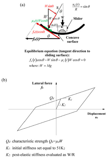
Figure 1.
Representation of the free-body diagram of the FPS under imposed lateral force and related equilibrium equation to translation in horizontal direction of the slider. (a) Theoretical non-linear hysteretic response of the FPS device (b).
Mechanical behavior of single-concave FPS devices may be idealized according to the non-linear hysteretic model proposed by [29], characterized by the definition of 3 parameters: the characteristic strength with W = Mg; the stiffness after the elastic behavior ; the stiffness in the elastic regime K1, assumed equal to 51∙K2. The representation of the theoretical hysteretic model for the FP device is reported in Figure 1b. Regarding friction coefficient in a dynamic regime, investigations of [31] suggest that can be expressed as being dependent on the sliding velocity as follows:
where the terms and represents the values of the coefficient of friction in regimes of high and low, respectively, velocity of sliding ; α represents a constant that governs the variation of the coefficient of friction between minimum and maximum values.
2.2. Modelling Mechanical Behaviour of Masonry Infills for Seismic Assessment
The principal role of infills in framed buildings derives from the need to confine the external environment from the internal one or to separate the internal compartments. As widely recognized, the masonry panels are able to interact with the surrounding RC structural frame in the presence of significant lateral actions [32,33]. This interaction produces both positive and negative effects on the overall response of the structure, as can be deduced from the post-earthquake observed damage scenarios [34]. In fact, although the overall stiffness of the structural system turns out to be increased, the presence of infills leads to a reduction in the natural period with the related increase in the seismic spectral acceleration. Moreover, with particular reference to partially infilled panels, their presence provides additional stiffness locally, increasing the shear demand on columns that can collapse with brittle mechanisms (e.g., captive and short column effects) [35]. For instance, despite the inevitable modeling issues, neglecting such elements in the refined non-linear analysis of RC frames may not allow to properly estimate the actual stiffness, resistance, and ductility of the structure system [33,36,37]. The scientific literature proposes different approaches to account for masonry infills within the definition of numerical models of RC frames. These ones can be classified primarily as micro-modeling and macro-modeling [37].
In the present investigation, the macro-modeling approach is adopted according to [37] for the fully infilled masonry panels to consider the effects deriving from the interaction between the infills and RC members. Specifically, they are reproduced by means of a single-strut model able to take into account the masonry mechanical non-linearities. According to [37], the strut can be defined by adopting a fiber-modeling approach with fibers characterized by the appropriate constitutive law able to reproduce the macro-behavior of the masonry panel [37]. As suggested in [37,38], the above-mentioned constitutive law can be defined similarly to the one used for concrete, in which the peak strength , the corresponding deformation , the ultimate resistance , and the related deformation are assigned depending on the mechanical and geometric properties of the masonry, which are introduced in the next.
With reference to the macro-modeling of the partially infilled masonry panels, approaches able to take into account their non-linear behavior, without large uncertainties, are scarce in the scientific literature. For instance, they have been reproduced by means of a single-strut model with elastic behavior in order to take into account unfavorable effects related to shear demand on columns [35]. In order to characterize the geometrical configuration of the macro-model with a single strut for each partial infill under examination, a micro-model using shell elements has been defined using the SAP200 software platform [25] according to Figure 2. The thickness of the shell elements used for micro-modeling has been defined in accordance with the geometry of the masonry panel, while the interface between the shells and the surrounding RC frame has been reproduced using spring elements [25] able to take into account the friction between concrete and masonry (using a friction coefficient equal to 0.45 [37]).
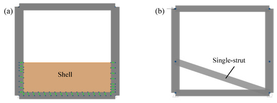
Figure 2.
Micro-model with shell (a) and macro-model with single-strut (b) using SAP2000 for partially in-filled masonry panels.
In order to define an equivalent macro-model, the width of the single strut was determined by a trial-and-error process until the same displacements, monitored at the top of the panel in the presence of horizontal force, were obtained for the macro-models with respect to the micro-models. The evaluation mentioned above has been performed for all the different geometrical configurations of the partial infills of the RC frame. The elastic properties of the material used for micro- and macro-models have been determined according to the actual masonry mechanical characteristics as reported in the next sections.
Finally, concerning masonry panels with large openings, they were not included within the numerical model as their contribution to overall stiffness can be neglected.
The macro-models of the masonry panels so far established have been adopted within the numerical model of the existing RC-framed structure with infills, as commented in the following.
3. Analyzed Irregular Building and Characterization of Retrofitting Intervention
In the present section, the description of the main features of the existing RC-framed building is reported. Then, some geometrical aspects of the retrofitting intervention using single-concave FP isolators are also described.
3.1. Geometrical Configuration of the Structure
The existing RC-framed building considered for the study is located in central Italy in a region with a very relevant seismicity. In particular, according to the current Italian design code [3], the region is subjected to PGA (peak–ground–acceleration) that is superior to 0.25 g and associated with an exceedance probability of 10−1 in 50 years concerning the life safety limit state. In the next section, the main geometrical features of the building are reported, focusing on the RC-framed structure and masonry infills. The building has been realized since the 1960s according to an Italian design code that, at the time, was related to seismic design for a small part of the specifications. For instance, the structure has been realized without appropriate seismic conception and detailing. The structure, built during the 1960s, is constituted by a cast in situ RC structure that consists of orthogonal frames dislocated along X (i.e., longitudinal) and Y (i.e., transverse) directions. The foundations are stiff, inverted, continuous RC beams along the direction of the RC frames. The in-plane sizes of the building are 59.8 m in the X direction and 12.2 m in the Y direction. Figure 3 illustrates, schematically, the column disposition with the related frames identified as X1, X2 in the X direction and Y1, Y2, Y3 along the Y direction.
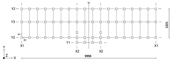
Figure 3.
In-plane size of the RC building; characterization of the RC frames according to X and Y orthogonal directions [26]. Dimensions in centimeters.
With reference to the elevation, the maximum height of the building is equal to 15.9 m measured from the foundation level. The RC structure presents 5 stories, including the roof level. The details of the geometry of the different RC frames that constitute the structure are reported in Figure 4 and Figure 5. Concerning the boundary conditions, around the structure for a height of 3.5 m measured from the foundation level, there is a soil embankment that is able to limit displacements in the X and Y directions of story 1. This is a relevant aspect of the seismic behavior of the structure, and it is accounted for during the definition of the numerical model.
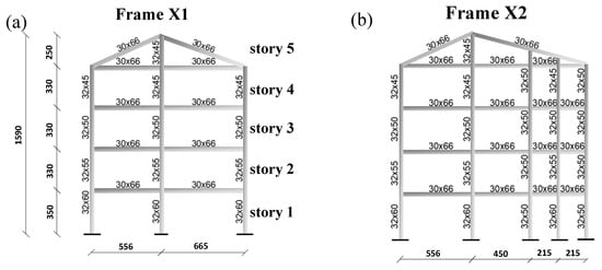
Figure 4.
Details of the RC frames that constitute the structure, including cross-sections of main members in X direction. Reprinted/adapted with permission from [26]. Dimensions in centimeters.
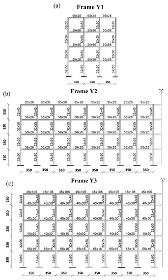
Figure 5.
Details of the RC frames that constitute the structure, including cross-sections of main members in direction Y. Reprinted/adapted with permission from [26]. Dimensions in centimeters.
Different types of members (i.e., columns and beams) are present, as illustrated in Figure 6. The reinforcement arrangement (both for shear and bending) concerning each member is summarized in Table 1. Data from inspections denote that the clear concrete cover (on average) is equal to 3 cm for all structural members. The horizontal floors are built using a lightened “latero-concrete” technical solution with RC joists and a top slab. The RC joists are 16 cm high with a base of 10 cm with 0.5 m as center-to-center distance in the transverse direction. They are oriented along the longitudinal direction (X), that is, according to the short beam floor pattern. The top slab is 4 cm thick and connects the joists realizing the floor, and, for modeling purposes, it can be considered sufficient to realize a rigid floor able to transfer horizontal actions to the longitudinal and transverse RC frames [3].

Figure 6.
Characterization of beams and columns within the RC structure. Reprinted/adapted with permission from [26]: (a) typical story; (b) roof.

Table 1.
Shear and bending reinforcements for main members of the RC frames [26].
The only external masonry infills have been considered to be able to contribute to the overall seismic response of the building. In particular, the masonry infills have a total thickness equal to 34 cm and are realized with the following stratigraphy: external facing in exposed brick (8 cm); air cavity (13 cm); internal facing in perforated bricks (12 cm); and internal cement plaster (1 cm). The disposition of the partially infilled and totally infilled masonry panels within the external RC frames of the structure is reported in Figure 7. It can be noted that the geometry of the external infills in the longitudinal direction is particularly unfavorable due to the presence of many partial infill panels.
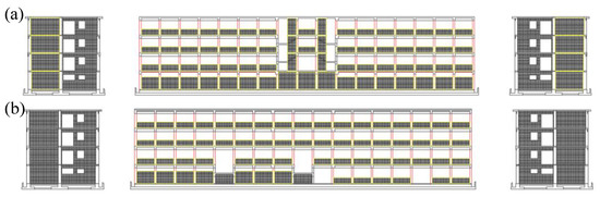
Figure 7.
Identification of external totally and partially masonry infilled frames. Frontal and lateral views of the building (a); back and lateral views of the building (b).
The adoption of FPS devices for the here-described refurbishment has been exploited by means of the introduction of a disjunction between the foundation level and superstructure in correspondence with the columns of story 1, as shown in Figure 8. In detail, the columns at the base of story 1 can be cut, and, thanks to the use of temporary supports, the FP devices can be installed. Moreover, the tops of the columns at the level of the substructure (i.e., below the isolator devices) have been connected by RC beams to enhance the robust response of the structure equipped with FPS against the potential malfunction of one or more of the devices [5]. More details about the isolation system design are given in the next sections.
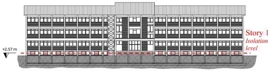
Figure 8.
Position of the isolation level (red dashed line) with location of the single-concave FP devices.
3.2. Characterization of Material Properties of the RC Structure and Masonry Panels
The determination of the materials’ mechanical characteristics has been performed by means of destructive and non-destructive tests. With reference to the “knowledge levels” (KL) approach [3], the achieved level of knowledge was compatible with the third one (i.e., KL3). For instance, the confidence factor [3] for material properties can be adopted as equal to 1.00. Then, the material properties used for the non-linear numerical analyses and structural verifications will be equal to the mean ones (i.e., experimental) for concrete, reinforcement, and masonry. The mean values of material properties have been determined according to a statistical analysis of test results. In detail, the cylinder concrete compressive strength (mean value) fcm has been determined by means of destructive testing of cores drilled from several structural elements. Its value, after statistical treatment of the data, has been estimated at 25.2 MPa. On a few sampled concrete cores, measurements of axial strain levels have been conducted with the aim of quantifying the value of the secant elastic modulus Ecm (mean value). The value of Ecm turns out to be equal to 22,000 MPa.
As for the steel reinforcement bars (FeB38k), the related characteristics have been estimated by means of tensile tests on specimens of reinforcing bars taken from different structural components. The mean value of the tensile yielding fym strength turned out to be equal to 374 MPa.
In addition, tests on masonries were carried out to determine the mechanical parameters, such as elastic modulus Em1,2 (in horizontal and vertical directions, respectively), and shear strength fvm by diagonal compression tests. The vertical compressive strength fm2 was instead inferred through the use of the Italian standard [3] depending on the masonry panel stratigraphy. The horizontal compressive strength fm1 has been considered equal to 50% of fm2 [3]. All the parameters mentioned above should be considered mean values and are summarized in Table 2. These values are adopted according to the methods for macro-modeling introduced in Section 2.2 with the aim to reproduce the influence on the structural behavior of masonry infills.
Table 2.
Mechanical properties of masonry panels.
4. Non-Linear Numerical Modelling and Structural Analysis
In the next section, the assumptions adopted to define the numerical models [25] and to perform the NL dynamic simulations of the investigated RC building are listed in agreement with [26], Refs. [39,40] and also with reference to the characterization of ground motion inputs.
4.1. Definition of the NL Numerical Models Related to RC Framed Building including Infills for Base-Fixed and Base-Isolated Structure
The RC-framed building under investigation has been numerically reproduced in line with the geometrical and material characteristics introduced in the previous sections using SAP2000 [25]. As for the modeling of the RC columns, it has been performed with the assumption of full restraint at the level of the rigid inverted RC beams that constitute the foundations of the building. Furthermore, the behavior of the stiff fields of “latero-cement” floors has been reproduced by appropriate membrane constraints in SAP2000 [25]. As introduced in previous sections, the building, up to the level of story 1, is surrounded by an embankment of soil. The presence of the latter has been included within the numerical representation of the structures, accounting for its restraining effect for in-plane (i.e., X and Y directions) displacements of story 1 [26].
Concerning the modeling of the main structural elements, characterized by RC columns and RC beams, a discretization approach based on fiber cross-section has been adopted with the aim of defining the non-linear behavior of the plastic hinges according to the concentrated plasticity philosophy (SAP2000 [25]). Specifically, for each type of cross-section, the constitutive laws of the fibers have been distinguished between steel longitudinal reinforcement, core (i.e., confined by stirrups), and cover concrete. The plastic hinges based on fiber discretization allow for taking into account the axial load and bending (biaxial) inter-relationship [25]. The non-linear response of the hinges takes place within a predetermined length Lp that denotes the plastic hinge length. The plastic hinge length Lp has been determined in line with the equation proposed by [41].
The constitutive law of [42,43] has been adopted to simulate non-linear responses in compressions of fibers representing the core and the cover concrete. The related tensile behavior has been modeled by means of LTS (i.e., linear tension softening). All the needed mechanical characteristics of concrete have been obtained as a function of the mean value of the experimental results for cylinder strength in compression fcm and modulus of elasticity Ecm in line with the specifications of EN1992 [44]. With the aim of taking into account the degradation of the mechanical properties due to the accumulation of damage during the seismic event, the model of [45] has been adopted.
With reference to the constitutive law for bar reinforcement, an elastic with perfect plasticity model has been used, taking care to limit the ultimate strain at a value of 7.5% [44]. According to the experimental tests, the mean value fym has been adopted as the yield strength concerning both the compressive and tensile behavior. The modulus of elasticity has been set to 200,000 MPa.
As anticipated in Section 2, the masonry infills have been modeled adopting a macro-modeling approach. The partially infilled panels have been modelled using “frame elements” in SAP2000 [25] that are active in compression only with elastic behavior. The geometric average elastic modulus of masonry between Em1 and Em2 has been adopted. The fully infilled frames have been modeled adopting the link element “Multilinear plastic” [25] active in compression only. The related force–displacement non-linear constitutive law has been derived according to [37] as explained in Section 2. The weight (and related mass) of the masonry infills have been considered within the numerical analyses as an additional permanent action on the RC frames.
As for modeling of FPS devices for the base-isolated building, the link element with non-linear behavior denoted as “Friction Pendulum” has been adopted according to the SAP2000 [25] library. The non-linear mechanical response of the links for what concerns the in-plane displacements along X and Y degrees of freedom (i.e., DOFs) has been defined according to the parameters affecting the FPS behavior as explained in Section 2 (i.e., R, K1, K2, and . The vertical displacement DOF of the link representing the FPS has been modeled with linear elastic behavior active in compression only.
The selection of the appropriate value of R is related to the achievement of a specific isolation period Tis of the building in line with Equation (1). With reference to Section 2, the stiffnesses K2 and K1 have been determined as a function of the axial load on the specific FPS isolator device. The friction coefficient in the dynamic regime as a function of time has been modeled in SAP2000 [25] according to [30,31]. The related value has been determined in the function of the axial load applied on each device with reference to the empirical approach of [30]. The summary of the properties associated with the different FPS isolators is reported in Table 3 together with their disposition in-plane as shown in Figure 9. As reported in Figure 10, four different numerical models have been realized, differentiating between the fixed-base/base-isolated structure without masonry infills and the fixed-base/base-isolated structure with masonry infills.
Table 3.
Properties of FPS devices in the function of the axial load.

Figure 9.
In-plane location of the single-concave FPS devices with different modeling characteristics. Reprinted/adapted with permission from [26].
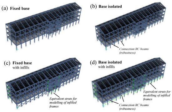
Figure 10.
NL numerical idealization for fixed-base (a) and base-isolated (b) structures without infills and fixed-base (c) and base-isolated (d) structures with infills using SAP 2000.
4.2. Definition of the Sesimic Inputs and Related Demand
The seismic demand has been determined by adopting as an intensity measure (IM) the value of the pseudo-acceleration Sa in the elastic regime. The site-related response spectrum associated with 50 years as a reference period for limit state of life safety has been adopted in line with [3]. The values of the damping coefficient have been distinguished between fixed-base and base-isolated structures, adopting 5% for the former and 2% for the latter one [12]. Figure 11 shows the adopted elastic response spectra.
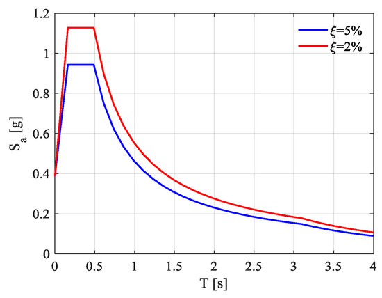
Figure 11.
Adopted response spectra in elastic regime according to limit state of life safety [3]. Reprinted/adapted with permission from [26].
The set of ground motion inputs to realize the NL dynamic simulations is composed of 21 natural records composed of 3 acceleration components along the in-plane and vertical directions, as used in [12] and further in [26]. In [12], the selection of the 21 inputs has been performed from the ESM (European–Strong–Motion database) [27]. The structural response of both fixed-base and base-isolated buildings has been investigated by means of modal analysis. Figure 12 reports the summary of the first three eigenmodes (and related periods of vibration) associated with the different structural configurations, including the influence of the infills. It can be highlighted that no significant variations in the modal shapes occur due to the presence of infills for both fixed-base and base-isolated structures. In the case of a fixed-base structure, as expected, the presence of the infills significantly reduces the periods of vibration due to their stiffening effects. On the contrary, the periods of vibration of the base-isolated structures are not strongly affected by the infills.
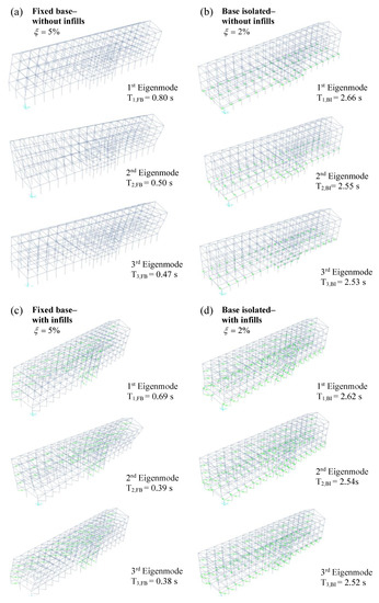
Figure 12.
Representation of the first three eigenmodes for the fixed-base structure with (a) and without infills (c) and for the base-isolated structure with (b) and without infills (d).
With the aim of ensuring spectrum compatibility with the spectra presented in Figure 11, each record has been properly scaled for what concerns the X-direction component. In particular, the IM evaluated in concomitance with the fundamental period T1 of the structure related to the elastic spectrum of the specific record has been scaled to the IM of the design spectra of Figure 11. This operation has been performed for both fixed-base and base-isolated structures, including and not including the effect of infills made of masonry. The response spectra related to the selected natural records and associated with the different structural configurations are shown in Figure 13 and Figure 14. Note that for the base-isolated infilled frame, the scaled records are almost equal to the ones corresponding to the base-isolated bare frame (i.e., without accounting for the infills). This demonstrates the minor influence of the presence of infills on the modification of the natural frequency of the base-isolated building. In general, the presence of the infills reduces from 0.80 s to 0.69 s the natural frequency of the fixed-base building.
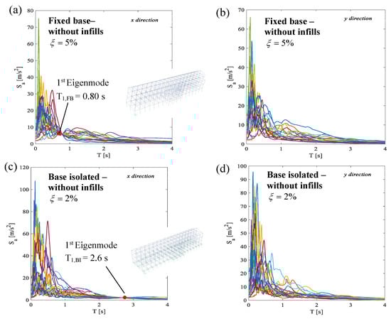
Figure 13.
Scaled spectra of pseudo-acceleration for fixed-base (a,b) and base-isolated (c,d) building related to natural seismic inputs along X (a–c) and Y (b–d) directions. Numerical models without infills.

Figure 14.
Scaled spectra of pseudo-acceleration for fixed-base (a,b) building related to natural seismic inputs along X (a) and Y (b) directions. Numerical models with infills.
4.3. Execution of the NL Dynamic Numerical Simulations for Investigated Building
The set of non-linear equations of motion under seismic input related to the analyzed building has been solved by means of the method of direct integration in line with [46,47]. Both geometric and mechanical non-linearities have been included in the analyses. As the modeling approach based on fiber-plastic hinges, as already described, does not account for the possible shear failure before the development of cross-section plasticity resources, specific shear verification has been performed according to EN1992 [44] for each step of the dynamic non-linear simulations.
With particular reference to the comparison between the fixed-base and base-isolated buildings, the presence of the FPS devices allows preventing the shear failure in columns where partial infills are located, resulting in a significant reduction in the short column effect.
The outcome of the NL dynamic simulations has been quantified in terms of the peak value of the inter-story drift index (IDI) for each story of the building for what concerns the in-plane directions (i.e., X, Y). In Figure 15a, the response of the corner FP device (that turns out to be the most critical one) to the seismic excitation associated with one of the scaled seismic inputs (i.e., the earthquake of “Emilia Pianura Padana 29 May 2012”) [27] (that corresponds to the EQ5 with reference to the database reported by [26]) is reported to demonstrate its agreement with the theoretical model of Figure 1b. In the force–displacement graph of Figure 15a, the irregularity of hysteresis cycles is due both to the variability of the dynamic coefficient of friction with the sliding velocity and to the effects induced by the vertical accelerometric component of the seismic record. Moreover, in Figure 15b,c, the IDIs, computed as average values between all the seismic records, are reported as a function of the building height from the foundation level for each numerical model herein considered. It can be recognized that the IDIs along the Y axis are smaller if compared to the ones along the X axis due to the different stiffness of the frames oriented in the Y and X directions, respectively. The results show a significant reduction in the IDIs in the presence of the isolation system, demonstrating its usefulness also in the case of irregular buildings. Comparing Figure 15b,c, the increase in stiffness can be appreciated due to the presence of masonry infills.
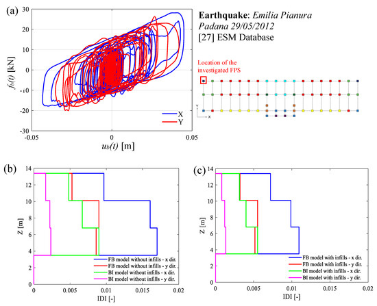
Figure 15.
Response of one of the FP devices under seismic excitation (a); parallelism related to mean value of the IDIs achieved for different stories for numerical models of fixed-base and base-isolated building without (b) and with (c) masonry infills.
5. Analysis of Structural Performance by Probability-Based Approach
Starting from the outcomes of the 3D NL dynamic simulations, the horizontal relative displacements of the isolators dFPS and IDIs have been the starting point to analyze the structural performance of both fixed-base and base-isolated systems in probabilistic terms. In particular, it has been assumed that both dFPS and IDIs are lognormally distributed [12], with mean value μ and standard deviation σ. By performing a statistical inference analysis, the hypothesis of lognormal distribution has passed the test with a significance level of 5%. The parameters of the probabilistic distribution have been computed adopting the maximum likelihood method according to [48]. In Figure 16 and Figure 17, the mono-variate lognormal distributions are illustrated by presenting either the results in terms of probability density functions (PDFs) or cumulative density functions (CDFs) and by making a comparison between the fixed-base and base-isolated structures, each of which considers once the absence of the masonry infills and once including those elements. Table 4 reports the limit state (LS) thresholds according to [28] in terms of IDI for both the structural systems (i.e., fixed-base and base-isolated) associated with an acceptable limit for the probability of exceedance in 50 years and 1 year.
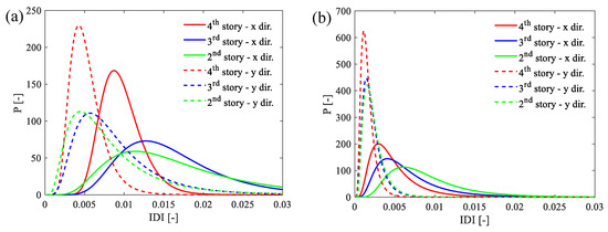
Figure 16.
Mono-variate log-normal distribution (PDFs) related to the IDIs oriented in X and Y direction: fixed-base model (a), base-isolated model (b); (without masonry infills). Reprinted/adapted with permission from [26].
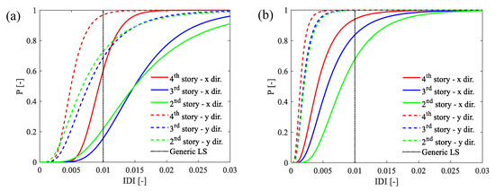
Figure 17.
Mono-variate log-normal distribution (CDFs) related to the IDIs oriented in X and Y direction: fixed-base model (a), base-isolated model (b); (without masonry infills). Reprinted/adapted with permission from [26].
Table 4.
Limit states thresholds in terms of IDI (FB and BI structure) [12,28].
Figure 16a,b reports, for both fixed-base and base-isolated buildings (without masonry infills), the mono-variate lognormal probability distribution functions obtained from the IDIs and considering different stories, while Figure 17a,b reports the related cumulative distribution functions.
In particular, Figure 17a,b illustrates, respectively, the mono-variate lognormal probabilistic and cumulative distribution functions of the dFPS including both the X and Y directions, for the base-isolated building (without masonry infills). First of all, it is shown that the horizontal displacement and the interstory drift index in the X direction are considerably larger than in the other direction, being less stiff in that direction. In addition, it is demonstrated that the retrofit allows a reduction in terms of the probability of exceedance Pf of the defined limit state. The exceedance probabilities for the isolation level and for both the fixed-base and base-isolated buildings (without masonry infills and considering the different stories) are shown in Figure 18a–c. It is shown that the isolation technique is able to decrease the IDIs and, thus, to significantly reduce the probability of exceedance if compared to the non-isolated structure.

Figure 18.
Mono-variate log-normal distribution (PDFs (a) and CDFs (b)) related to the in-plane relative displacement with respect to the ground of the isolation level oriented in X and Y direction (without masonry infills). Reprinted/adapted with permission from [26].
The previous conclusion is generally true with and without considering the presence of masonry infills, as shown in Figure 19 and Figure 20. As for the effects of the masonry infills, they can be highlighted as they affect the order of magnitude of the IDIs as well as the related exceeding probabilities.
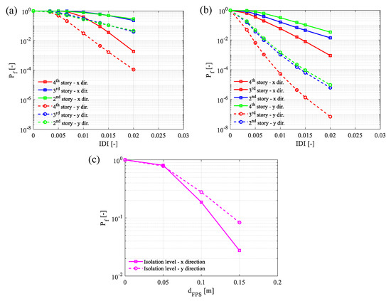
Figure 19.
Probabilities of exceedance with mono-variate assumption in logarithmic scale: fixed-base model (a); base-isolated model (b); isolator devices for base-isolated model (c); (without masonry infills). Reprinted/adapted with permission from [26].
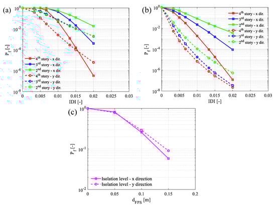
Figure 20.
Probabilities of exceedance with mono-variate assumption in logarithmic scale: fixed-base model (a); base-isolated model (b); isolator devices for base-isolated model (c); (with masonry infills).
Furthermore, the tri-dimensional response of either the fixed-base structure or the base-isolated structure can be performed by evaluating the degree of correlation between the abovementioned parameters IDIs and dFPS along the two directions X and Y of the planar scheme of the structure. Then, the joint log-normal distributions have been computed according to [12].
As far as the probability of failure in the case of jointly distributed variables is concerned, it must be calculated by integrating the generic JPDF, , where ZX denotes IDIx or dFPSx whereas ZY denotes IDIY or dFPS,Y. Figure 21, Figure 22, Figure 23, Figure 24, Figure 25, Figure 26, Figure 27 and Figure 28 illustrate mainly the level curves of the joint PDFs, together with a certain limit state area, considering the cases with and without masonry infills and for both fixed-based and base-isolated buildings. For example, regarding the superstructure, only results related to the 4th story and the 2nd story are presented.
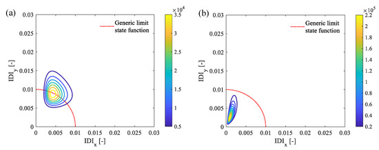
Figure 21.
Level curves of the joint PDF for the 4th story with a generic limit state: fixed-base model (a); base-isolated model (b); (without masonry infills).
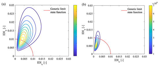
Figure 22.
Level curves of the joint PDF for the 2nd story with a generic limit state: fixed-base model (a); base-isolated model (b) (without masonry infills).
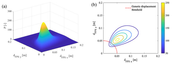
Figure 23.
Three-dimensional view of the joint PDF for the isolation story (a) and level curves (b) with a generic displacement threshold (without masonry infills).
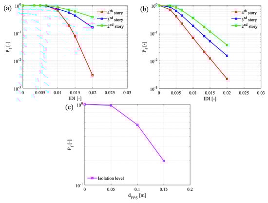
Figure 24.
Probabilities of exceedance with bi-variate log-normal assumption in logarithmic scale: fixed-base model (a); base-isolated model (b); isolator devices for base-isolated model (c); (without masonry infills).

Figure 25.
Level curves of the joint PDF for the 4th story with a generic limit state: fixed-base model (a); base-isolated model (b) (with masonry infills).
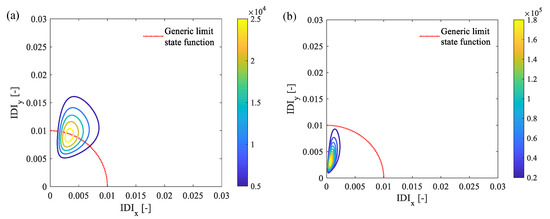
Figure 26.
Level curves of the joint PDF for the 2nd story with a generic limit state: fixed-base model (a); base-isolated model (b); (with masonry infills).
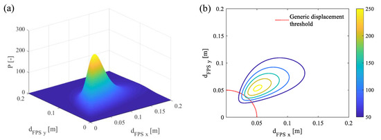
Figure 27.
Three-dimensional view of the joint PDF for the isolation system (a) and level curves (b) with a generic displacement threshold (with masonry infills).

Figure 28.
Probabilities of exceedance with bi-variate log-normal assumption in logarithmic scale: fixed-base model (a); base-isolated model (b); isolator devices for base-isolated model (c); (with masonry infills).
We can observe a much higher probability of exceedance when the parameters IDIs and dFPS are considered in both the planar directions of the building. This is mainly due to the good degree of correlation that always exists between the abovementioned parameters. Figure 25, Figure 26, Figure 27 and Figure 28 show how the presence of the infills leads to lower exceeding probabilities as well as a lower dispersion of the spatial response of the structure along its height, especially for the fixed-base structure.
In conclusion, in the case of retrofitting intervention using FP devices, the mentioned above results translate into a reduced damage level for fully operational (LS1) and operational (LS2) limit states, enhancing the recovery of functionality after seismic events. Moreover, with reference to the life safety (LS3) and near-collapse (LS4) limit states, the interaction between the FP isolation system and the presence of an infill wall reduces the probability of exceeding the related limit state thresholds as well as the potential direct (i.e., casualties, recovery, or rebuild of the structure) and indirect (i.e., loss of service of the building related to its function for the community) costs.
6. Conclusions
The present investigation aims to analyze the efficiency, in probabilistic terms, of using FPS with single concavity devices to retrofit an existing RC building with both in-plane and in-elevation irregularities. In particular, the interaction between the FP isolation system and the presence of an irregular distribution of infilled frames has been discussed. Appropriate NL numerical models of the structure have been defined on the basis of a concentrated plasticity approach using fiber-hinges cross-sections for both fixed-base and base-isolated structures, inclusive or not of the influence of masonry infills. Then, spatial NL dynamic simulations have been developed considering twenty-one natural seismic events with the three acceleration components.
The outcomes of the NL dynamic simulations highlight that the presence of the FPS isolators allows for a drastic reduction in the values of the IDIs, limiting the occurrence of local failures of columns in shear. In particular, in the base-isolated structure, shear failure in columns where partial infills are located is prevented in comparison to the fixed-base building. The presence of masonry infills improves the effectiveness of the isolation system by further reducing the displacement demand. These abovementioned effects are then quantified in probabilistic terms by computing the lognormal distribution functions on the IDIs and on the relative displacement with respect to the ground of FPS isolators, adopting both mono-variate and bi-variate approaches. As expected, the probabilities of exceedance show a significant drop between the fixed-base building and the base-isolated building. This result is confirmed and even magnified by the structural effect of masonry infills, highlighting the importance of accounting for their influence during the seismic assessment of existing buildings. In fact, their contribution can be a determining factor in satisfying the performance requirements of current design codes without the need for strengthening interventions on structural members. In conclusion, further developments should be carried out in order to estimate the seismic reliability of such a structure, including the site-dependent seismic hazard and investigating the contribution of infills to enhance its safety.
Author Contributions
Conceptualization, D.G., E.M. and L.G.; methodology, D.G., E.M. and L.G.; software, D.G., E.M. and L.G.; validation, D.G., E.M. and L.G.; formal analysis, D.G., E.M. and L.G.; investigation, D.G., E.M. and L.G.; resources, D.G., E.M. and L.G.; data curation, D.G., E.M. and L.G.; writing—original draft preparation, D.G., E.M., L.G., G.C.M. and P.C.; writing—review and editing, D.G., E.M., L.G., G.C.M. and P.C.; visualization, D.G., E.M. and L.G.; supervision, D.G., E.M., L.G., G.C.M. and P.C. All authors have read and agreed to the published version of the manuscript.
Funding
This research received no external funding.
Informed Consent Statement
Not applicable.
Data Availability Statement
Not applicable.
Acknowledgments
This work is part of the collaborative activity developed by the authors within the framework of the Commission 3—Task Group 3.1: “Reliability and safety evaluation: full-probabilistic and semi-probabilistic methods for existing structures” of the International Federation for Structural Concrete (fib). This work is also part of the collaborative activity developed by the authors within the framework of the WP 11—Task 11.4—ReLUIS. This work is also part of the collaborative activity developed by the authors within the framework of the “PNRR–VS3 “Earthquakes and Volcanos”–WP3.6”.
Conflicts of Interest
The authors declare no conflict of interest.
References
- Gino, D.; Castaldo, P.; Bertagnoli, G.; Giordano, L.; Mancini, G. Partial factor Bulletin 80: Assessment of an existing prestressed concrete bridge. Struct. Concr. 2020, 21, 15–31. [Google Scholar] [CrossRef]
- Clemente, P.; Buffarini, G.; Dolce, M.; Parducci, A. La scuola Angeli di San Giuliano: Un esempio significativo di isolamento sismico. Energ. Ambiente Innov. 2009, 3, 107–116. [Google Scholar]
- NTC18; Aggiornamento Delle Nuove Norme Tecniche per le Costruzioni DM 17.01.2018. Ministero delle Infrastrutture e dei Trasporti: Rome, Italy, 2018.
- EN 1998-1; General rules, seismic actions and rules for buildings. CEN European Committee for Standardization: Bruxelles, Belgium, 2004.
- Castaldo, P.; Mancini, G.; Palazzo, B. Seismic reliability-based robustness assessment of three-dimensional reinforced concrete systems equipped with single-concave sliding devices. Eng. Struct. 2018, 163, 373–387. [Google Scholar] [CrossRef]
- Mishra, S.K.; Roy, B.K.; Chakraborty, S. Reliability-based-design-optimization of base isolated buildings considering stochastic system parameters subjected to random earthquakes. Int. J. Mech. Sci. 2013, 75, 123–133. [Google Scholar] [CrossRef]
- Valente, M.; Milani, G. Alternative retrofitting strategies to prevent the failure of an under-designed reinforced concrete frame. Eng. Fail. Anal. 2018, 89, 271–285. [Google Scholar] [CrossRef]
- Zou, X.K.; Wang, Q.; Li, G.; Chan, C.M. Integrated reliability-based seismic drift design optimization of base-isolated concrete buildings. J. Struct. Eng. 2010, 136, 1282–1295. [Google Scholar] [CrossRef]
- Christopoulos, C.; Filiatrault, A. Principles of Passive Supplemental Damping and Seismic Isolation; IUSS Press: Pavia, Italy, 2006. [Google Scholar]
- Su, L.; Ahmadi, G.; Tadjbakhsh, I.G. Comparative study of base isolation systems. J. Eng. Mech. 1989, 115, 1976–1992. [Google Scholar] [CrossRef]
- Zayas, V.A.; Low, S.S.; Mahin, S.A. A simple pendulum technique for achieving seismic isolation. Earthq. Spectra 1990, 6, 317–333. [Google Scholar] [CrossRef]
- Castaldo, P.; Palazzo, B.; Della Vecchia, P. Seismic reliability of base-isolated structures with friction pendulum bearings. Eng. Struct. 2015, 95, 80–93. [Google Scholar] [CrossRef]
- Castaldo, P.; Alfano, G. Seismic reliability-based design of hardening and softening structures isolated by double concave sliding devices. Soil Dyn. Earthq. Eng. 2020, 129, 105930. [Google Scholar] [CrossRef]
- Briseghella, B.; Zordan, T.; Liu, T.; Mazzarolo, E. Friction Pendulum System as a Retrofit Technique for Existing Reinforced Concrete Building. Struct. Eng. Int. 2013, 23, 219–224. [Google Scholar] [CrossRef]
- Mazza, F.; Mazza, M.; Vulcano, A. Base-isolation systems for the seismic retrofitting of r.c. framed buildings with soft-storey subjected to near-fault earthquakes. Soil Dyn. Earthq. Eng. 2018, 109, 209–221. [Google Scholar] [CrossRef]
- Yang, T.; Bergquist, S.; Calvi, P.M.; Wiebe, R. Improving seismic performance using adaptive variable friction systems. Soil Dyn. Earthq. Eng. 2021, 140, 106442. [Google Scholar] [CrossRef]
- Mazza, F.; Vulcano, A. Nonlinear dynamic response of r.c. framed structures subjected to near-fault ground motions. Bull Earthq. Eng. 2010, 8, 1331–1350. [Google Scholar] [CrossRef]
- Lupășteanu, V.; Soveja, L.; Lupășteanu, R.; Chingălată, C. Installation of a base isolation system made of friction pendulum sliding isolators in a historic masonry orthodox church. Eng. Struct. 2019, 188, 369–381. [Google Scholar] [CrossRef]
- D’Amato, M.; Gigliotti, R.; Laguardia, R. Seismic Isolation for Protecting Historical Buildings: A Case Study. Front. Built Environ. 2019, 5, 87. [Google Scholar] [CrossRef]
- De Angelis, A.; Pecce, M.R. The Role of Infill Walls in the Dynamic Behavior and Seismic Upgrade of a Reinforced Concrete. Fram. Build. Front. Built Environ. 2020, 6. [Google Scholar] [CrossRef]
- Celarec, D.; Ricci, P.; Dolsek, M. The sensitivity of seismic response parameters of the uncertain modeling variables of masonry-infilled reinforced concrete frames. Eng. Struct. 2012, 35, 165–177. [Google Scholar] [CrossRef]
- Celik, O.C. Effect of AAC infill walls on structural system dynamics of a concrete building. J. Earthq. Eng. 2015, 20, 738–748. [Google Scholar] [CrossRef]
- Vasani, M.H.; Ramani, D. Comparative study of effect of infill walls on fixed base and base isolated reinforced concrete structures. JETIR 2017, 4, 379–384. [Google Scholar]
- Shiroll, S.; Kori, J.G. Seismic Base Isolation of RC Frame Structures with and without Infill. Int. Res. J. Eng. Technol. 2017, 4, 1783–1792. [Google Scholar]
- SAP2000; CSI Analysis Reference Manual: For SAP2000. ETABS, SAFE and CsiBridge: Berkeley, CA, USA, 1975.
- Gino, D.; Anerdi, C.; Castaldo, P.; Ferrara, M.; Bertagnoli, G.; Giordano, L. Seismic Upgrading of Existing Reinforced Concrete Buildings Using Friction Pendulum Devices: A Probabilistic Evaluation. Appl. Sci. 2020, 10, 8980. [Google Scholar] [CrossRef]
- ESM Database. European Strong Motion Database. Available online: http://www.isesd.hi.is/ (accessed on 20 March 2020).
- Bertero, R.D.; Bertero, V.V. Performance-based seismic engineering: The need for a reliable conceptual comprehensive approach. Earthq. Eng. Struct. Dyn. 2002, 31, 627–652. [Google Scholar] [CrossRef]
- Naeim, F.; Kelly, J.M. Design of Seismic Isolated Structures: From Theory to Practice; John Wiley & Sons, Inc.: Hoboken, NJ, USA, 1999. [Google Scholar]
- Constantinou, M.C.; Mokha, A.; Reinhorn, A.M. Teflon bearings in base isolation. II: Modeling. J. Struct. Eng. 1990, 116, 455–474. [Google Scholar] [CrossRef]
- Constantinou, M.C.; Whittaker, A.S.; Kalpakidis, Y.; Fenz, D.M.; Warn, G.P. Performance of Seismic Isolation Hardware under Service and Seismic Loading; Technical Report MCEER-07-0012; University of Buffalo: Buffalo, NY, USA, 2007. [Google Scholar]
- Aristomenis, V.; Tsantilis, T.; Triantafillou, C. Innovative seismic isolation of masonry infills using cellular materials at the interface with the surrounding RC frames. Eng. Struct. 2018, 155, 279–297. [Google Scholar]
- Fardis, M.N.; Panagiotakos, T.B. Seismic design and response of bare and infilled reinforced concrete buildings—Part II: Infilled structures. J. Earthq. Eng. 1997, 1, 473–503. [Google Scholar] [CrossRef]
- De Risi, M.T.; Del Gaudio, C.; Verderame, G.M. Evaluation of repair costs for masonry infills in RC buildings from observed damage data: The case-study of the 2009 L’Aquila earthquake. Buildings 2019, 9, 122. [Google Scholar] [CrossRef]
- Guevara, L.T.; Garcia, L.E. The captive- and short-column effect. Earthq. Spectra 2005, 21, 141–160. [Google Scholar] [CrossRef]
- Dolsek, M.; Fajfar, P. Mathematical modeling of an infilled RC frame structure based on the results of pseudo-dynamic tests. Earthq. Eng. Struct. Dynam. 2002, 31, 1215–1230. [Google Scholar] [CrossRef]
- Di Trapani, F.; Bertagnoli, G.; Ferrotto, M.F.; Gino, D. Empirical equations for the direct definition of stress–strain laws for fiber-section-based macromodeling of infilled frames. J. Eng. Mech. 2018, 144, 04018101. [Google Scholar] [CrossRef]
- Scott, B.D.; Park, R.; Priestley, M.J.N. Stress–strain behavior of concrete confined by overlapping hoops at low and high strain rates. ACI J. 1982, 79, 13–27. [Google Scholar]
- Castaldo, P.; Gino, D.; Bertagnoli, G.; Mancini, G. Resistance model uncertainty in non-linear finite element analyses of cyclically loaded reinforced concrete systems. Eng. Struct. 2020, 211, 110496. [Google Scholar] [CrossRef]
- Castaldo, P.; Gino, D.; Mancini, G. Safety formats for non-linear analysis of reinforced concrete structures: Discussion, comparison and proposals. Eng. Struct. 2019, 193, 136–153. [Google Scholar] [CrossRef]
- Priestley, M.J.N.; Park, R. Strength and ductility of concrete bridge columns under seismic loading. ACI Struct. J. 1987, 84, 61–76. [Google Scholar]
- Mander, J.B.; Priestly, M.J.N.; Park, R. Theoretical stress-strain model for confined concrete. J. Struct. Eng. 1988, 114, 1804–1826. [Google Scholar] [CrossRef]
- Saatcioglu, M.; Razvi, R.S. Strength and ductility of confined concrete. J. Struct. Eng. 1992, 118, 1590–1607. [Google Scholar] [CrossRef]
- EN 1992-1-1; Eurocode 2—Design of concrete structures. Part 1-1: General rules and rules for buildings. CEN: Brussels, Belgium, 2014.
- Takeda, T.; Sozen, M.A.; Nielsen, N.N. Reinforced Concrete Response to Simulated Earthquakes. J. Struct. Engrg. Div. ASCE 1970, 96, 2257–2273. [Google Scholar] [CrossRef]
- Hilber, H.M.; Hughes, T.J.R.; Taylor, R.L. Improved numerical dissipation for time integration algorithms in structural dynamics. Earthq. Eng. Struct. Dyn. 1977, 5, 283–292. [Google Scholar] [CrossRef]
- Cheng, F.Y. Matrix Analysis of Structural Dynamics: Applications and Earthquake Engineering; CRC Press: Boca Raton, FL, USA, 2001. [Google Scholar]
- Faber, M.H. Statistics and Probability Theory; Springer: Berlin/Heidelberg, Germany, 2012. [Google Scholar]


Disclaimer/Publisher’s Note: The statements, opinions and data contained in all publications are solely those of the individual author(s) and contributor(s) and not of MDPI and/or the editor(s). MDPI and/or the editor(s) disclaim responsibility for any injury to people or property resulting from any ideas, methods, instructions or products referred to in the content. |
© 2023 by the authors. Licensee MDPI, Basel, Switzerland. This article is an open access article distributed under the terms and conditions of the Creative Commons Attribution (CC BY) license (https://creativecommons.org/licenses/by/4.0/).