Abstract
Three-dimensional blading is an efficient technique in compressor aerodynamic design, and its function mechanism in the cantilevered stator needs to be addressed. This paper focuses on the sweep and dihedral in the cantilevered stator and seeks to expose their effects through detailed flow field analysis. Results show that the forward sweep could alleviate the corner flow separation by preventing the accumulation of the secondary flow toward the corner region, resulting in stronger flow separation at the blade trailing edge; in summary, forward sweep with appropriate parameters could increase static pressure rise by 14.3%. The positive dihedral will carry the endwall flow to the upper-span sections, thereby reducing blade corner separation; hence, as much as 23.5% improvement in static pressure rise could be obtained with the appropriate dihedral. Moreover, the combination of a relatively large sweep height and a moderate sweep angle with a low dihedral height and a moderate sweep angle provides optimum aerodynamic performance; the static pressure rise coefficient sees an increment of 25.5% at the near stall point. An experiment is then performed to further validate the theory, which shows a 2% improvement in efficiency of 3D blading at small mass flow rates. However, the secondary leakage should be given attention at high mass flow coefficients, while the corner separation needs further elimination at small mass flow rates.
1. Introduction
The cantilevered stator is signified by its simple structure and low weight and hence is a promising configuration in the high-performance compressor. However, the leakage flow created by the radial gap at the stator root substantially complicates the endwall flow, necessitating a thorough understanding and advanced design techniques. Dean stated in the 1950s that the cantilevered stator could obtain better aerodynamic performance than the shrouded stator [1]. His conclusion was then verified experimentally by Lakshminarayana and Horlock, who also pointed out the existence of an optimum clearance size [2,3,4]. Although the leakage flow could, in a way, benefit endwall flow, it will at the same time introduce flow blockage and mixing loss; thus, studies have been conducted to reveal the flow mechanisms in the corner region. For example, Singh and Ginder, Lee et al., and George et al. believe the leakage flow weakens the corner separation by suppressing the endwall flow [5,6,7], whereas Gbadebo et al. argue that it is the suppression of the horseshoe vortex in the leading edge that causes removal of the corner separation [8]. Dong et al. state that the suppression of corner separation is mainly caused by the mixing of the high-energy leakage flow with the low-energy corner flow [9]. In terms of the clearance size, Lakshminarayana et al. proposed that the optimum choice is when the strengths of the leakage flow and the secondary flow are identical [2,4], whereas Gbadebo et al. revealed that the clearance flow tends to strengthen the corner separation when the clearance size is very small [8]. While George et al. proposed an optimum hub clearance of 1% blade height [5], the optimum stator clearance remains in question [9,10,11,12,13]. Tanwar et al. investigated the hub clearance height and found that the interaction of hub leakage and passage vortex leads to mitigation of overall secondary flow adverse effects [14].
Three-dimensional blading can improve the compressor aerodynamic performance through reorganization of the flow field and hence is widely used in axial compressors. In general, 3D blading can be classified as sweep and dihedral. It is well known that the forward sweep of the rotor blade tip can reduce the local inlet Mach number, thereby weakening the shock wave and reducing the loss [7,13,15,16,17,18,19,20]. The sweep of the blade can also be used to control the corner flow in the subsonic compressor. As for the dihedral, it is recognized that the positive dihedral can construct a radial pressure gradient in the blade passage, thereby weakening the accumulation of the boundary layer at the corner region and inhibiting the occurrence of flow separation. According to the research of Breugelmans et al. and Weingold et al., the positive dihedral at both ends of the blade can reduce the endwall loss but will increase the loss in the midspan areas [21,22]. Sasaki further notes that the beneficial effect of positive dihedral on the near-wall region is mainly related to the dihedral angle, whereas the negative effect at the midspan is determined by the dihedral height [23]. More information on 3D blading can be found in references [24,25].
Although the application of 3D blading is quite common in conventional rotors/stators, there are few reports about its utilization in the cantilevered stator. Lange et al. attributed the beneficial effect of dihedral to the improvement of the rotor flow according to their experimental measurements [26]. Tweedt et al. found that the forward sweep can draw the high-momentum flow to the corner region of the suction surface, thereby suppressing the thickening of the viscous flow [20]. Lu et al. performed a numerical investigation of the effect of the forward sweep in the cantilevered stator, indicating that a reasonable sweep can not only reduce the shock wave at the stator hub but also reduce the loading near the blade leading edge [27]. Gunn and Hall found that the loss of the non-axisymmetric cantilevered stator with undistorted inflow could be 10% lower than conventional stator [28]. From the above analysis, it can be seen the application of 3D blading in the cantilevered stator is prospective in further improving the compressor aerodynamic performance, and the current attempt is limited to individual sweep or dihedral. To further optimize the cantilevered stator, a comprehensive understanding of the 3D blading mechanism is required, and guidelines for the compound sweep and dihedral design are necessary.
The present paper seeks to shed light on the utilization of 3D blading in the cantilevered stator; it is organized as follows: Section 2 gives an introduction of the investigation methods. Section 3 numerically investigates the effect of the sweep, dihedral, and compound sweep and dihedral, through which the flow mechanisms are revealed, and recommendations of the different parameters are provided. The theory is then validated by an experiment, which consists of the redesign of a cantilevered stator and a detailed comparison of the flow field with the datum scheme, as shown in Section 4. The main conclusions are summarized in Section 5.
2. Research Object and Investigation Methodology
The effects of the 3D blading are investigated both numerically and experimentally in the present work. An introduction of the 3D modeling parameters will be given in this section, followed by details of the research methodology.
2.1. Geometric Definition of the 3D Blading
This paper employs the widely used Sweep-Dihedral Coordinates to define the 3D blading parameters [25,29,30]. As shown in Figure 1, the displacement of the blade section in the chordwise direction is called “sweep”. Meanwhile, an obtuse angle between the endwall and leading-edge stacking line in the meridional plane is defined as a forward sweep. On the other hand, the displacement of the blade section in the direction perpendicular to the blade chordwise is called “dihedral”. Similarly, an obtuse angle between the endwall and blade stacking line in the meridional plane designates a positive dihedral, and vice versa.
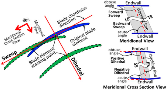
Figure 1.
Definitions of 3D blade design in the orthogonal coordinates.
2.2. Numerical Simulation Method
The cantilevered stator to be investigated comes from the aft stage of a highly loaded high-pressure compressor, whose hub clearance is constant at 1% blade height. As shown in Figure 2, The numerical simulation is performed under the stage environment, with the simulation domain containing three blade rows: the IGV, the rotor, and the stator. The domain inlet is 2.0 times the chord length upstream of the IGV, while the domain outlet is 3.5 times the chord length downstream of the stator blade. The structured grid was generated using NUMECA Autogrid5; the main blade region and the clearances adopt the O4H topology and the H-O topology, respectively. Moreover, the grid is clustered at the near-wall region to satisfy the requirements of the turbulent model; y+ of the first grid off wall is about 2.5 in the region close to the transition position, and the number is smaller near the trailing edge. After grid independence analysis with grid density, the total grid number for the rotor and stator blade rows was 1.28 million and 1.45 million, respectively [31,32]. For a 1.5-times finer mesh, the variation of the loss, the static pressure rise coefficient, and the flow angle compared with the selected mesh is less than 0.1%.
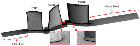
Figure 2.
Model configuration and simulation grid.
This paper uses the commercial software ANSYS CFX 18.0 to explore the effects of the 3D blading techniques; previous studies have found that the two-equation eddy-viscosity models could simulate the complex vortex flows in the low-speed compressor with satisfying accuracy [33,34]. As a low-speed compressor (Ma ~ 0.2), the atmospheric condition (101,325 Pa, 288.15 K) was imposed at the domain inlet, where the total pressure was specified using a circumferential averaged radial profile obtained from experimental results. The mass flow rate was given at the outlet. Rotational periodic conditions were applied to the side walls, whereas the solid walls were defined as the adiabatic non-slip walls. The rotating speed of the rotor was 1100 rpm, and the interface between the rotor and the stator was modeled as the mixing plane. As for the turbulent model, the standard k-ω model was chosen, as it can capture more accurate 3D flow details than the standard k-ε model, while obtaining a better convergence than the SST model [19,35]. A combination of the second-order spatial and temporal numerics are selected for the transport equations.
To ensure calculation accuracy, in addition to the default parameters, self-defined parameters, including the compressor pressure ratio, efficiency, and the inlet/outlet mass flow rate, were monitored during the simulation process. The flow field was considered converged when the mass flow discrepancy at the domain inlet and outlet was smaller than 0.1%.
2.3. Experimental Method
To check the effect of the 3D blading technique, a cantilevered stator in the existing test facility was redesigned and measured experimentally to reveal the variations of the flow field. The experiment was conducted in the low-speed large-scale axial compressor (LSLSAC) test facility at Beihang University. As shown in Figure 3a, the LSLSAC, whose hub-to-tip ratio is 0.75, adopts the 1.5 stage configuration, with a row of inlet guide vanes. The rotor and stator blades are nearly radially stacked by the controlled diffusion airfoil (CDA). The rotating speed is 1100 rpm, which is the same as the numerical simulation. At the design point, the stage loading coefficient is approximately 0.46 (based on midspan velocity), whereas the nominal rotor tip clearance and stator hub clearance are 1.5% and 1.0% blade height, respectively.
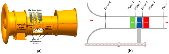
Figure 3.
Schematics of the LSLSAC. (a) Geometry configuration; (b) measurement locations.
As shown in Figure 3b, five measurement planes are arranged along the axial direction, where multiple static pressure taps are installed on the casing wall. The mass flow coefficient is monitored by the four circumferential static pressure taps at Plane 0, while the static pressure rise of the compressor is measured by circumferential static pressure taps at Plane 1 and Plane 5. The outlet total pressure is measured by the pitot probes at Plane 5. It should be mentioned that the inlet total pressure is the ambient pressure, which is measured by an atmospheric pressure gauge. Moreover, a torque meter is used to measure the input shaft power to the compressor, which is utilized to calculate the efficiency of the compressor. The torque efficiency is calculated as follows:
where M denotes the torque, n is the rotating speed, and m0 and are the mass flow rate and the total temperature at the compressor inlet (Plane 0), respectively.
To obtain the 3D velocity and pressure profiles at the stator inlet and outlet, measurement at Planes 3 and 4 was executed using an L-shaped five-hole probe. In the radial direction, the nearest measurement point to the hub and the shroud wall was 2.0% and 2.5% blade height, respectively. Moreover, a novel zonal method was utilized to process the pressure data, through which the measurement angle range was extended to ±60° [36]. The pressure was acquired by the Rosemount pressure transducers, whose measurement range and uncertainty were ±6.22 KPa and 0.025% FS, respectively. Error analysis demonstrated that the measurement uncertainties of the five-hole probe were 0.5° for the flow angles, 1% (normalized by the flow dynamic pressure) for the total pressure, 2% (normalized by the flow dynamic pressure) for the static pressure, and 1% for the flow velocity [36].
In the present study, oil-flow visualization tests were conducted to exhibit the flow patterns in the stator blade passage. The material used to make the skin-friction lines was a mixture of industrial silicone. The running time of each test was between 5 and 10 min.
3. Effects of 3D Blading on the Cantilevered Stator
To reveal the effect of 3D blading on the cantilevered stator, a parametric investigation of the 3D modeling parameters was first conducted. Numerical simulation was employed to evaluate the various design schemes.
3.1. Effects of the Blade Sweep
In the present work, the forward sweep was employed to control the corner flow. To determine the sweep height and the sweep angle, the effect of these two parameters are discussed. As specified in Table 1, the sweep height is varied between 30% and 70% of the total blade height, whereas the sweep angle is between 120° and 150°. The modeling schemes are named by the following rule: “parameter type + index + parameter type + index”. For example, scheme “A1B1” designates a sweep starting from 30% blade span with a sweep angle of 120°.

Table 1.
Modeling scheme for blade sweep.
3.1.1. Effects of the Sweep Height
The influence of sweep height is first compared using the control variate method. As shown in Figure 4, the design schemes are A1B2, A2B2, and A3B2. A slight forward sweep is also adopted at the tip region to balance the pressure gradient in the radial direction (135°, 70% span). Results are compared to the orthogonal/straight blade (Orth.). Note that no dihedral is utilized in this section.
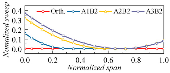
Figure 4.
Radial distribution of blade sweep for the cases with different sweep heights.
The pressure rise and loss characteristics of the cantilevered stators are demonstrated in Figure 5. Results show that, except for the near-stall condition of A1B2, the utilization of the forward sweep could always improve the stator aerodynamic performance in comparison to the baseline case. Moreover, the comparison of different schemes indicates that the 60% sweep height (A2B2) outperforms the other designs. At the near-stall condition, the static pressure rise coefficient and the total pressure loss coefficient in A2B2 are increased and decreased by 14.3% and 5.4%, respectively.
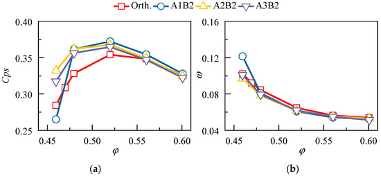
Figure 5.
Pressure rise and loss characteristics for the stator with different sweep heights. (a) Pressure rise and (b) loss.
Figure 6 illustrates the flow field distribution for the cases with different sweep heights. Both the leakage streamlines and the surface streamlines are depicted. Results show that the forward sweep moves the hub leakage flow upstream, thus enhancing the hindrance to the secondary flow and attenuating the accumulation of the low-energy fluid toward the corner region. Consequently, the blockage at the corner region of the suction surface witnesses a remarkable shrink. However, the forward sweep will incur the radial expansion of the suction surface flow separation; hence, the wake is broadened in the upper span areas. Moreover, under the same mass flow ratio, the sweep height exhibits little effect on the leakage flow but will influence the trailing edge separation significantly. At the sweep height of 60% blade span (A2B2), the trailing edge separation tends to be uniform along the radial direction, thus bringing optimum aerodynamic performance.
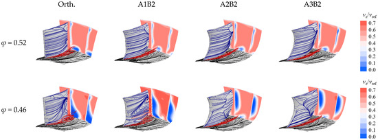
Figure 6.
Flow field distribution for the cases with different sweep heights.
To evaluate the aerodynamic performance of the cantilevered stator quantitatively, the radial distribution of the aerodynamic parameters is given in Figure 7. The variation of the mass flow coefficient suggests that the forward sweep is able to improve the flow capacity in the hub region, whereas the alleviation of corner separation flow brings a reduction in the deviation angle. The effect of the forward sweep is more pronounced at small mass flow ratios (i.e., the conditions with higher loading). By comparing different blading schemes, it can be seen that the larger sweep height adds to the beneficial effect. Nevertheless, when the sweep height is greater than 60% (A3B2), the performance improvement at the corner region by further increasing the sweep height becomes less significant, yet the upper span performance starts to deteriorate; hence, the 60% sweep height is suitable for the present case.
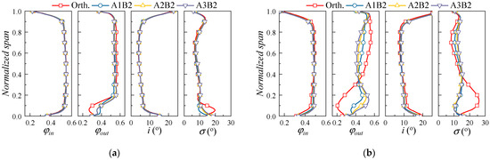
Figure 7.
Radial distribution of aerodynamic performance for the cases with different sweep heights. (a) φ = 0.52; (b) φ = 0.46.
To reveal the effect of sweep height on the leakage flow, the variation of the mass flow rate of the leakage flow is presented in Figure 8. Results indicate that the leakage flow rate first decreases in the areas between 0~20% blade chord and then continues to increase toward the trailing edge. The increase in the mass flow rate of the leakage flow will enhance the removal of low-energy fluid in the corner region of the blade suction surface, thus confirming the former analysis. Additionally, although increasing the sweep will enhance the 3D blading effect, the leakage characteristics of the A2B2 case and the A3B2 case exhibit similar patterns; hence, further increasing the sweep height will result in less benefit.
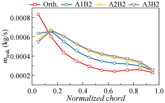
Figure 8.
The comparison of the streamwise leakage mass flow rate under different sweep heights (φ = 0.46).
3.1.2. Effects of the Sweep Angle
To investigate the influence of the sweep angle, the design schemes A2B1, A2B2, and A2B3 are compared in this section, as illustrated in Figure 9. A tip region of each case employs the forward sweep at the 70% span with the same sweep angle as the hub. The orthogonal/straight blade works as the benchmark of comparison.
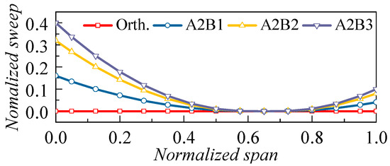
Figure 9.
Radial distribution of blade sweep for the cases with different sweep angles.
Figure 10 presents the pressure rise and loss characteristics of the cantilevered stators. It can be seen that the aerodynamic performances of different design schemes share similar trends; except for the near-stall condition, the pressure rise coefficients are enhanced significantly in comparison with the orthogonal blade. Observation of the near-stall condition indicates that the sweep angle should be controlled within a proper range, as a too-large sweep angle (A2B3, 150°) will deteriorate the blade pressure rise coefficient; however, the performance remains better than that of the straight blade.
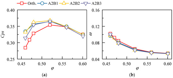
Figure 10.
Pressure rise and loss characteristics for the stator with different sweep angles. (a) Pressure rise and (b) loss.
The flow field distributions for the design schemes with different sweep angles are given in Figure 11. Similar to the previous conclusions, the forward sweep will weaken the flow separation in the blade corner region, but at the same time enhance the flow separation at the midspan. With the increase of the sweep angle, the leakage flow tends to move toward the pressure surface of the adjacent blade, thus increasing the traveling distance to the outlet. Consequently, the mixing of the leakage flow with the corner flow is improved, and the radial dimension of the low-speed area at the blade outlet shrinks. It should be noted that excessively large sweep angle will lead to a significant increase in the suction surface flow separation (A2B3), thereby weakening the aerodynamic performance gains brought by the forward sweep; thus, the sweep angle should be appropriately selected when at the design stage.
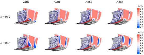
Figure 11.
Flow field distribution for the cases with different sweep angles.
The radial distribution of the aerodynamic parameter for the cases with different sweep angles is given in Figure 12. Results of both the φ = 0.52 and the φ = 0.46 conditions are provided. With the increase of sweep angle, the flow coefficient at the hub region increases, resulting in the improvement of the flow capacity. On the contrary, the flow capacity at the upper span parts is decreased, corresponding to the widening of the blade wake in Figure 11. The influence of the sweep angle on the radial flow of the blade is more significant at small mass flow rates. Considering the influence of the sweep angle on the corner flow and the blade separation flow, a moderate sweep angle (approximately 135° for the present study) is appropriate for the cantilevered stator.
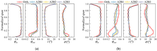
Figure 12.
Radial distribution of aerodynamic performance for the cases with different sweep angles. (a) φ = 0.52; (b) φ = 0.46.
Figure 13 presents the variation of the mass flow rate for the stator leakage flow along the streamwise direction. Increasing the sweep angle tends to reduce the leakage flow at the blade leading edge, yet it will enhance the leakage flow in the other regions. The total mass flow rate of the leakage flow will be increased upon the utilization of the forward sweep, thus strengthening the interaction of different corner flow structures.
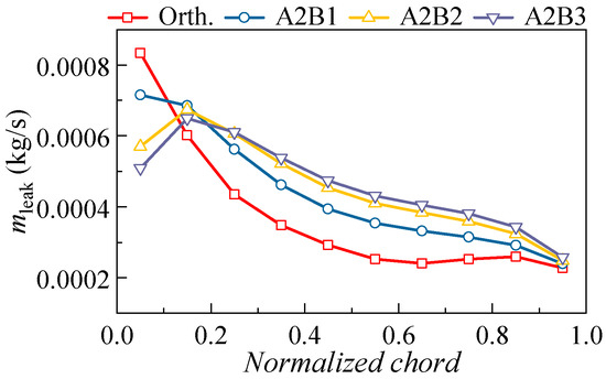
Figure 13.
The comparison of the streamwise leakage mass flow rate under different sweep angles (φ = 0.46).
Hence, the forward sweep could inhibit the transverse flow near the hub endwall and alleviate the flow separation at the corner region. Increasing the sweep height facilitates a uniform separation along the span without changing the endwall flow significantly.
3.2. Effects of the Blade Dihedral
3.2.1. Effects of the Dihedral Height
Except for the forward sweep, the positive dihedral is also adopted in the present study to optimize the stator performance. Therefore, the effects of the dihedral height and dihedral angle need to be clarified. As shown in Table 2, the dihedral height is varied between 20% and 60% of the total blade height, whereas the dihedral angle is between 120° and 150°. The modeling schemes are named following the same rule as that of the sweep (e.g., scheme “C1D1” corresponds to a dihedral starting from 30% blade span with a dihedral angle of 120°).
Table 2.
Modeling scheme for blade dihedral.
Likewise, the influence of dihedral height is first compared using the control variate method. As shown in Figure 14, the design schemes are C1D3, C2D3, and C3D3. A slight positive sweep is also adopted at the tip region (150°, 90% span). Simulation results are compared to the orthogonal/straight blade (Orth.); note that no sweep is utilized in this section.
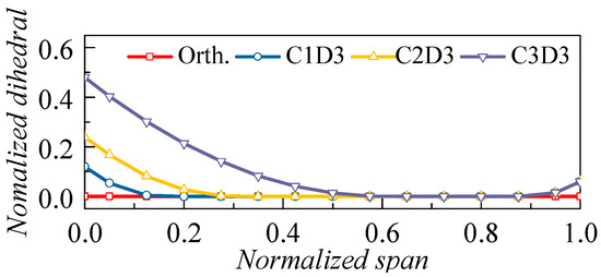
Figure 14.
Radial distribution of blade dihedral for the cases with different dihedral heights.
Figure 15 presents the pressure rise and loss characteristics for the design schemes with different dihedral heights. Compared with the orthogonal blade, the scheme with a small dihedral height (C1D1) could improve the diffusing capacity of the cantilevered stator without increasing its total pressure loss, thus improving the aerodynamic performance of the cantilevered stator. However, with the increase of the dihedral height (C2D3 and C3D3), the blade loss will start to rise, and the pressure rise capacity is reduced remarkably, thus eliminating the advantages of the positive dihedral.
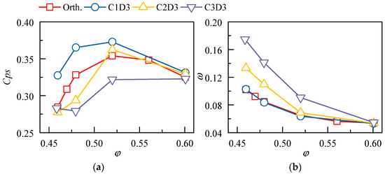
Figure 15.
Pressure rise and loss characteristics for the stator with different dihedral heights. (a) Pressure rise and (b) loss.
To determine the reason why increasing the dihedral height will reduce the stator performance, the flow field distribution was established for the cases with different dihedral heights, as presented in Figure 16. Results at the mass flow coefficient of 0.52 demonstrate that the positive dihedral will not only push the trajectory of the leakage vortex away from the blade suction surface but also promote the radial migration of the low-energy fluid. In scheme C1D3, the dihedral height is relatively low, and the accumulation of low-energy fluid at the corner region of the blade suction surface is reduced by the circumferential migration of the leakage flow. Therefore, the blockage at the blade outlet is alleviated significantly. With the increase of the dihedral height (C2D3), although the corner separation at the stator hub is weakened effectively, the wake in the lower and middle parts of the blade is elongated and widened remarkably, which is detrimental to the comprehensive aerodynamic performance of the cantilevered stator. Moreover, if the dihedral height is further increased to 60% (C3D3), the leakage flow will undergo an obvious radial migration under the strong blade force. As a result, the separation at the blade trailing edge will be significantly enhanced, and the performance of the cantilever stator will further deteriorate. Note that with the decrease of the mass flow coefficient, the influence of the dihedral amplifies substantially.

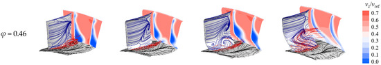
Figure 16.
Flow field distribution for the cases with different dihedral heights.
The radial distribution of the aerodynamic parameter for the cases with different dihedral heights is given in Figure 17 to evaluate the stator performance quantitively. The increase of incidence angle at the hub region indicates that the positive dihedral will restrict the flow capacity at the blade inlet, while increasing the dihedral height will amplify the effect. On the other hand, the mass flow coefficient at the outlet of the cantilevered stator distributes differently with the variation of the dihedral height. For scheme C1D3, the flow capacity below 20% blade height is increased significantly due to the weakening of the corner separation flow, Meanwhile, the mass flow coefficient in the areas above 20% span witnesses a slight reduction owing to the enhancement of the trailing edge separation, the deviation angle also rises correspondingly. With the increase of the dihedral height (C2D3 and C3D3), the flow capacity above 20% blade height suffers from a significant reduction because of the strengthening of the radial flow migration in the blade channel, thus bringing adverse effects to the aerodynamic performance of the cantilevered stator.
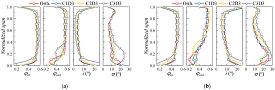
Figure 17.
Radial distribution of aerodynamic performances for the cases with different dihedral heights. (a) φ = 0.52; (b) φ = 0.46.
Figure 18 presents the variation of the leakage mass flow rate. An interesting phenomenon is that increasing the dihedral height will first increase and then decrease the leakage mass flow rate at the blade leading edge. Consequently, the uniformity of the leakage flow characteristic along the blade chord is first decreased and then increased. Moreover, although the slight positive dihedral (C1D3) could increase the mass flow rate of the leakage flow along the axial direction, increasing the dihedral height will incur a significant reduction of leakage flow at the blade leading edge, thus weakening the effect of the 3D blading technique.
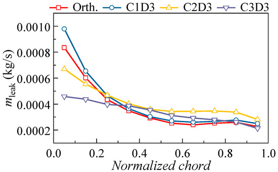
Figure 18.
Comparison of the streamwise leakage mass flow rate under different dihedral heights (φ = 0.46).
3.2.2. Effects of the Dihedral Angle
To investigate the influence of the dihedral angle, under the optimum dihedral height, the stator performances with different dihedral angles are inspected. As illustrated in Figure 19, the cases to be investigated are C1D1, C1D2, and C1D3; note that the blade tip also adopts positive dihedrals (at 80% span with the same dihedral angle as the hub) to balance the pressure gradient in the radial direction.
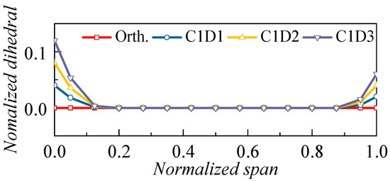
Figure 19.
Radial distribution of blade dihedral for the cases with different dihedral angles.
The pressure rise and loss characteristics for the design schemes with different dihedral heights are demonstrated in Figure 20. The influence of the dihedral is more pronounced in terms of pressure rise coefficient and at small mass flow ratios. In comparison to the orthogonal blade, the positive dihedral will always improve the blade static pressure coefficient, whereas the increment will first increase and then decrease with the increase of the dihedral angle. The optimum dihedral angle in the present study is 135°, where the value of Cps is improved by 23.5% at the near-stall condition.
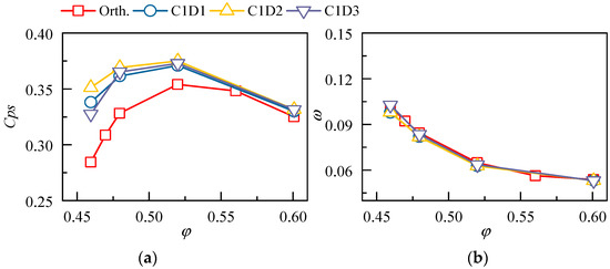
Figure 20.
Pressure rise and loss characteristics for the stator with different dihedral angles. (a) Pressure rise and (b) loss.
The flow field distributions at the mass flow coefficients of 0.52 and 0.46 are given in Figure 21. It is apparent that the leakage flow will deviate from the blade suction surface with the increase of the dihedral angle. As a result, the mixing of the leakage flow with the mainstream is more sufficient, and the blockage at the outlet alleviates. However, the increase of the dihedral angle will also enhance the radial migration of the blade corner flow, thus strengthening the flow separation on the suction surface. Of all the design schemes, C1D2 could not only suppress the secondary flow at the hub endwall but also avoid excessive flow separation on the blade suction surface, hence obtaining the optimum aerodynamic performance.
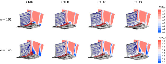
Figure 21.
Flow field distribution for the cases with different dihedral angles.
As shown in Figure 22, the influence of the dihedral angle on the performance of the cantilevered stator is illustrated clearly. Results show that the current dihedral angles barely influence the distribution of the mass flow coefficient at the stator inlet; however, the mass flow distribution at the stator outlet is altered. To be specific, at the φ = 0.52 condition, the mass flow coefficient in the lower and upper regions of the 20% blade height is increased and decreased, respectively, which echoes the flow field characteristics in Figure 21. The comparison of different design schemes indicates that with the increase of the dihedral angle, the enhancement of flow capacity at the stator hub will become inconspicuous, yet the worsening of aerodynamic performance at the upper span becomes more significant, which consequently weakens the total beneficial effect. The above phenomenon is more significant at small mass flow ratios.
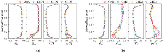
Figure 22.
Radial distribution of aerodynamic performances for the cases with different dihedral angles. (a) φ = 0.52; (b) φ = 0.46.
Figure 23 presents the variation of the leakage mass flow rate. Results demonstrate that although the mass flow rate of the leakage flow is increased slightly in comparison with the orthogonal blade, the current range of the dihedral angle barely influences the axial distribution of the leakage flow, and the absolute mass flow rates for different blading schemes are approximately identical.
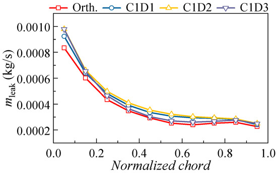
Figure 23.
Comparison of the streamwise leakage mass flow rate under different dihedral angles (φ = 0.46).
Hence, the positive dihedral will not only push the trajectory of the leakage vortex away from the blade suction surface but also promote the radial migration of the low-energy fluid at the hub corner. A large dihedral height will elongate the blade wake and induce the radial transportation of the leakage flow.
3.3. Effects of the Compound Sweep and Dihedral
According to the former analysis, the mechanism of 3D blading in the cantilevered stator is summarized in Figure 24. The forward sweep can enhance the hindrance of the leakage flow on the low-energy fluid near the endwall, while flow separation on the blade suction side is exaggerated slightly. Increasing the sweep height facilitates a uniform separation along the span without changing the endwall flow significantly, whereas excessively large sweep angles lead to a large-scale separation on the blade suction surface and harm the total effect. On the other hand, as shown in Figure 24b, the positive dihedral will not only push the trajectory of the leakage vortex away from the blade suction surface but also promote the radial migration of the low-energy fluid at the hub corner. The utilization of large dihedral heights will elongate the blade wake and induce the radial transportation of the leakage flow, while the excessive dihedral angle will damage the performance at the midspan.
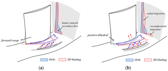
Figure 24.
The mechanisms of sweep and dihedral on the cantilevered stator: (a) sweep; (b) dihedral.
In consideration of the effects above, a novel cantilevered stator with comprehensive sweep and dihedral is designed, whose aerodynamic performance is evaluated via numerical simulation. As shown in Figure 25, the 3D cantilevered stator employs a relatively high sweep height with a moderate sweep angle, and the dihedral is designed to have a low height and a moderate angle. Note that the blade tip also adopts a forward sweep to balance the radial pressure gradient.
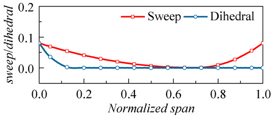
Figure 25.
Radial distribution of sweep and dihedral for the 3D cantilevered stator.
Figure 26 presents the pressure rise and loss characteristics of the 3D cantilevered stator; results of the orthogonal blade, the bare sweep scheme (no dihedral), and the bare dihedral scheme (no sweep) are also provided for the convenience of comparison. Figure 26 implies that the combination of the sweep and dihedral will intensify the beneficial effects, as the “sweep + dihedral” scheme has the highest static pressure ratio and the lowest total pressure loss over the whole operating range. At the near-stall point, the static pressure rise coefficient and the total pressure loss coefficient are increased and decreased by 25.5% and 11.1%, respectively. Given the remarkable improvement over the baseline case, it is safe to say that the working mechanism summarized above is correct, and the redesign is successful. The following section will outline the experimental methods used to validate the conclusions.
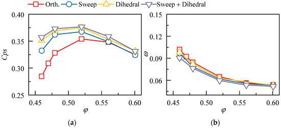
Figure 26.
Pressure rise and loss characteristics for the 3D cantilevered stator. (a) Pressure rise; (b) loss.
4. Application of 3D Blading in a Cantilevered Stator
4.1. The Redesign of the Cantilevered Stator
The design parameters of the datum stator are shown in Table 3, with the diffusion factor varying from 0.58 to 0.35 from hub to tip. Moreover, the stator hub clearance occupies 1% of the blade height, which proved beneficial for the stator aerodynamic performance in a previous study [37]. Since the datum stator was comparable to the orthogonal cantilevered stator in the former study, the 3D blading strategy in Figure 25 is adopted for the redesign scheme.
Table 3.
Design parameters for the highly loaded cantilevered stator.
Figure 27 presents the comparison of the aerodynamic performances of the datum and redesigned cantilevered stators. To improve the simulation accuracy, the numerical simulation considers the stator blade row separately and imposes the experimentally measured flow fields at the stator inlet according to the specific operating conditions. In the datum case, the pressure rise capability of the cantilevered stator will drop significantly once the mass flow coefficient is below 0.53, due to the deterioration of flow conditions at the hub corner (Figure 28). On the other hand, the stator with 3D blading can overcome the above problem efficiently, as the Cps is increased by 71.8% at the mass flow coefficient of 0.45 (P1). The total pressure loss coefficient for the redesigned case is reduced remarkably as well, implying the effectiveness of the 3D blading scheme.
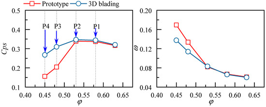
Figure 27.
Comparison of pressure rise and loss characteristics of the cantilevered stators.
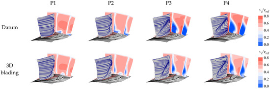
Figure 28.
The comparison of field distribution between the datum and the redesigned stator.
As shown in Figure 28, the comparison of the flow field under different operating conditions (P1~P4, see Figure 27) indicates that the datum stator suffers from severe corner flow separation at the near-stall condition, leading to the sudden drop of the pressure rise capacity. Meanwhile, the utilization of compound sweep and dihedral reorganizes the flow field; hence, the accumulation of low-energy fluid at the hub corner is relieved significantly, corresponding to the performance improvement in Figure 27. Note that the flow separation in the upper span areas is intensified in comparison with the datum scheme, which is due to the radial migration of the low-energy fluid from the positive dihedral.
The radial distribution of the aerodynamic parameters is given in Figure 29 to illustrate the effect of 3D blading quantitively. Results show that the 3D blading can enhance the through flow capacity at the hub region over a wide operating range, as the mass flow distribution is more uniform along the radial direction. The beneficial effect extends from 15% to 50% span as the operating point moves from P1 to P4, which is consistent with the former analysis. Moreover, the total pressure loss demonstrates the advantage of 3D blading in reducing the near-stall loss, yet the effect is less remarkable under larger mass flow coefficients when the flow field is naturally healthy. The following section will outline the experimental methods used for further validation.
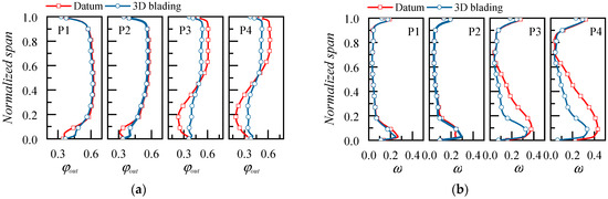
Figure 29.
The radial distribution of mass flow coefficient and loss under different operating conditions: (a) outlet mass flow coefficient; (b) total pressure loss.
4.2. Discussion of the Experimental Results
4.2.1. Effect of 3D Blading on the Aerodynamic Performance
To start, the overall aerodynamic performance of the compressor stage is compared, as shown in Figure 30. Results highlight that the 3D blading on the cantilevered stator could significantly improve the performance of the compressor stage at small mass flow conditions; at the near stall condition (P4), the total pressure rise coefficient and the efficiency are increased by 3% and 2%, respectively. However, as the operating point moves to the right, the 3D blading will start losing its advantage, and the stage efficiency at φ > 0.51 will even drop by 0.7%. As only stator blades have been changed, Figure 31 shows the loss characteristics of the cantilevered stators, in which the CFD results are also plotted to present the deviation between the experiment result and the CFD result. Figure 31 indicates the CFD results have high reference value, so the above numerical analysis results are credible.
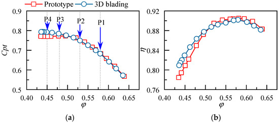
Figure 30.
Comparison of performance characteristics of the compressor stage: (a) total pressure rise coefficient; (b) efficiency.
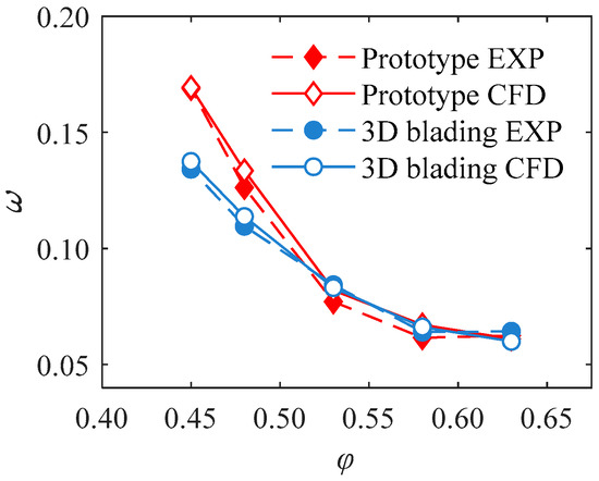
Figure 31.
Comparison of loss characteristics of the cantilevered stators between experiment and CFD.
Turning to the stator blade row, Figure 32a presents the variation of the stator total pressure loss coefficient with the stage mass flow coefficient. In comparison with the datum scheme, the total pressure loss of the 3D cantilevered stator is reduced significantly; the absolute reduction reaches 0.035 at the near-stall point (P4), or 20.5%. However, the loss of the cantilevered stator will increase slightly at higher mass flow conditions; the maximum increment is 0.008 at φ = 0.53, which is acceptable in consideration of its advantage under other conditions. Additionally, the variation of the stator loss coincides with the trend on the stage level, thus implying that the variation of compressor stage performance in Figure 30 is attributed mainly to the 3D bladed stator. In order to further quantify the impact of 3D blading on different regions of the cantilevered stator, the total loss is decomposed along the blade span, as shown in Figure 32b–d. The blade is classified into three regions according to the mass flow, i.e., the hub region (0~25% total mass flow), the middle region (25~75% total mass flow), and the tip region (75~100% total mass flow). Results show that the loss reduction of the 3D stator stems mainly from the hub and midspan regions, which is consistent with the weakening of corner flow separation in these areas. Moreover, the utilization of the forward sweep turns out to improve the tip region over the whole operating range, which signifies the necessity of balancing radial flow in the design process.
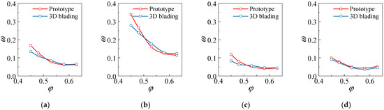
Figure 32.
Comparison of loss characteristics of the cantilevered stator: (a) total loss, (b) hub loss, (c) midspan loss, and (d) tip loss.
The radial distribution of the mass flow coefficient for the cantilevered stator is illustrated in Figure 33. Results show that the 3D blading barely influences the mass flow distribution at the stator inlet, whereas it could improve the throughflow capacity at the hub region over a wide operating range. The distribution of mass flow coefficient at the stator outlet exhibits a similar pattern to that in Figure 29, which proves the accuracy of the numerical simulation. On the other hand, the mass flow coefficient in the lower span areas of the stator outlet sees a remarkable increment at P2~P4 conditions, implying the flow capacity near the endwall is enhanced via the combination of the forward sweep and dihedral. It should be noted that at the P1 condition, the mass flow coefficient of a 10~40% span is reduced for the 3D blading scheme, which indicates the flow capacity is weakened in these regions. The mass flow at the midspan areas is first increased and then decreased as the operating point moves from P1 to P4, owing to the redistribution of radial flow. The effect of 3D blading is more pronounced at small mass flow coefficients, thus confirming the former investigation.
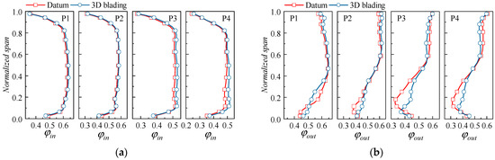
Figure 33.
The radial distribution of mass flow coefficients under different operating coefficients: (a) inlet mass flow coefficient; (b) outlet mass flow coefficient.
Figure 34 presents the distributions of the blockage coefficient and the total pressure loss coefficient. The variation of the blockage denotes that the 3D blading could generally relieve the flow blockage at the hub corner, thereby creating a healthier flow field. However, the blockage coefficient of a 10~40% span is increased at the P1 condition, which corresponds to the reduction of mass flow ratio in Figure 33b. As for loss characteristics, large amounts of loss reduction are brought by the 3D blading at small mass flow conditions (P3 and P4), whereas the beneficial effect is less distinctive at large mass flow ratios (P1 and P2).
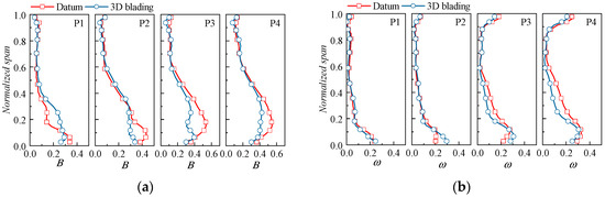
Figure 34.
The radial distribution of blockage and loss under different operating coefficients: (a) blockage; (b) total pressure loss.
4.2.2. Effect of 3D Blading on the Flow Field Distribution
To obtain an overview of the flow structures in the cantilevered stator, Figure 35 presents the oil-flow results of the datum stator. The separation line (SL) is denoted by the red solid line, the attachment line (AL) is denoted by the red dotted line, the spiral node is denoted by the letter F, and the saddle point is denoted by the letter S. It can be seen that at the P1 condition, under the blowing effect of the endwall leakage flow, the corner separation at the stator hub starts from the saddle point S1 and separates into S1-F1 and S1-F3 along the radial direction; the tip region also suffers corner flow separation. The upper and lower separation areas bounded by S1 are approximately symmetrical and located close to the blade trailing edge, whereas the separation region at the blade tip is independent of the hub corner separation. With the decrease of the mass flow coefficient, the corner flow separation first enlarges its radial scale at P2 and then changes the topology at P3: the separation line S1-F1 heads upstream, pushing F1 to the endwall and incurring the corner stall. According to Figure 35, the stator hub is severely blocked at the P3 condition, represented by the large-scale low-speed zone at the outlet. Further observation of the tip flow shows that at the near-stall conditions (P3, P4), the separation region at the stator hub and the tip will gradually merge at the trailing edge, which is also demonstrated in Figure 35. Finally, under the cantilevered geometry, the occurrence of the corner stall will only induce local separation flow at SL2, which is distinctively different from the conventional shrouded stator (represented by the large-scale endwall separation and a rapid expansion of the separation zone) [37,38,39].
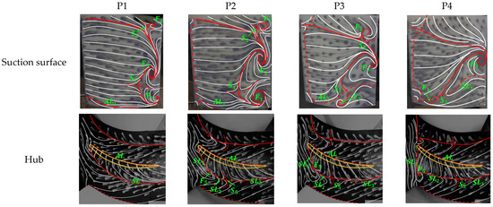
Figure 35.
Oil-flow results on the blade suction surface and hub wall for the datum stator.
Figure 36 presents the flow field distribution at the stator outlet, where the results of both the datum stator and the 3D bladed stator are demonstrated. It can be observed that the 3D blading can effectively push the leakage flow away from the blade suction surface, yet it will incur secondary leakage at the large flow conditions (in P1 and P2, the leakage flow moves into adjacent blade channel). As a result, the flow separation at the blade trailing edge is enhanced slightly. With the decrease of mass flow rate, both the leakage flow and the transverse secondary flow will be enhanced by the increase of the circumferential pressure gradient, while the difference in their variation rate makes the leakage flow approach the blade suction surface and finally accumulate toward the hub corner of the blade surface (P3 and P4). In fact, it is only at the near-stall conditions when the 3D blading manifests its advantage: at P3 and P4, the flow separation is weakened in the middle and lower part of the stator, thereby alleviating the blockage in the middle and lower span areas. Moreover, the forward sweep at the stator tip turns out to improve the flow field in the meantime, as the wake is narrowed correspondingly.
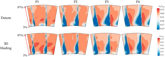
Figure 36.
The distribution of the normalized axial speed at the stator outlet.
To further reveal the mechanism of 3D blading in the corner flow in the cantilevered stator, Figure 37 presents the comparison of the secondary flow velocity vector at the stator outlet. Traces of the secondary flow (CF) and the leakage flow (LF) are depicted to demonstrate the flow structures with better clarity. Apparently, the leakage flow that travels from the blade pressure surface to the suction pressure surface could hinder the circumferential migration of the secondary flow. In the datum scheme, the CF travels through the bottom of the LF and climbs to the blade suction surface, inducing a counterclockwise vortex on its left side and a clockwise vortex on its right side. Upon the utilization of 3D blading, the strengthening of the leakage flow enhances the inhibition effect of the LF on the CF, leading to secondary leakage at the P1 and P2 conditions. As for P3 and P4 conditions, the flow separation in the corner region is reduced, owing to the weakening of the secondary flow.
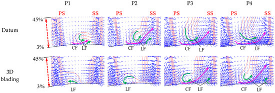
Figure 37.
Distribution of secondary flow velocity vector at the stator outlet.
To sum up, the interaction between the endwall leakage flow and the transverse secondary flow determines the effect of the 3D blading. For the present cantilevered stator, at large mass flow rates, the experimental results demonstrate that the 3D blading pushes the leakage flow too close to the pressure side of the adjacent blade, thereby inducing secondary leakage. However, at small mass flow rates, the inhibition of the leakage flow to the endwall secondary flow is not strong enough; hence, the corner separation requires further elimination. The above results also imply that the design of 3D blading needs to optimize the evolution of corner flow structures at different operating conditions.
5. Conclusions
This study focuses on the utilization of 3D blading in the cantilevered stator and seeks to reveal its mechanism in improving the compressor aerodynamic performance. The main conclusions are drawn as follows:
- The forward sweep can inhibit the transverse flow near the hub endwall and alleviate the flow separation at the corner region, while flow separation on the blade suction side was exaggerated slightly. Increasing the sweep height facilitates a uniform separation along the span without changing the endwall flow significantly, whereas excessively large sweep angles lead to a large-scale separation on the blade suction surface and harm the total effect;
- The positive dihedral not only pushes the trajectory of the leakage vortex away from the blade suction surface but also promotes the radial migration of the low-energy fluid at the hub corner. The utilization of large dihedral heights elongates the blade wake and induces the radial transportation of the leakage flow, while the excessive dihedral angle damages the performance at the midspan;
- The compound forward sweep and positive dihedral can combine the advantages of both strategies and provide better aerodynamic performance for the cantilevered stator, the benefit extends over the whole operating range and is more significant at lower mass flow ratios. In comparison to the orthogonal stator, the static pressure rise coefficient and the total pressure loss coefficient of the 3D bladed stator are increased and decreased by 25.5% and 11.1%, respectively;
- The compound sweep and dihedral were utilized to redesign a cantilevered stator in a low-speed compressor test facility. Experimental results demonstrate that the total pressure loss of the 3D cantilevered stator is reduced by 20.5% at the near-stall point, thus proving the effectiveness of the 3D blading technique. The advantage of 3D blading is more pronounced at small mass flow coefficients;
- The performance enhancement of the 3D blading stems mainly from the hub and lower span areas. At large mass flow ratios, the leakage flow leaks into the adjacent blade channel and causes secondary loss, yet at small mass flow rates, the inhibition of the leakage flow to the endwall secondary flow is not strong enough; hence, the corner separation needs further elimination. The design of the 3D cantilevered stator needs to optimize the evolution of corner flow structures over the operating range.
The validation of the 3D blading is conducted in the low-speed compressor test facility under the single-stage environment in the present study, and it would be meaningful if experiments could be implemented in high-speed and multi-stage environments in the future to reveal more flow mechanisms while validating the present conclusions.
Author Contributions
Conceptualization, G.A. and X.Y.; methodology, X.X., R.W. and G.A.; software, G.A.; validation, Y.Q., G.A. and X.Y.; formal analysis, X.X., R.W. and G.A.; investigation, X.X., Y.Q., R.W., B.L., G.A. and X.Y.; resources, Y.Q. and G.A.; data curation, Y.Q., X.X., R.W. and G.A.; writing—original draft preparation, X.X. and R.W.; writing—review and editing, R.W.; visualization, Y.Q., X.X. and R.W.; supervision, B.L.; project administration, B.L. and X.Y.; funding acquisition, B.L. All authors have read and agreed to the published version of the manuscript.
Funding
This research was funded by National Natural Science Foundation of China (Grant Nos. 52276025, 52206038), the National Science and Technology Major Project (J2019-II-0004-0024, J2019-II-0003-0023), the Advanced Jet Propulsion Innovation Center/AEAC (funding number HKCX2022-01-008), and the Fundamental Research Funds for the Central Universities.
Data Availability Statement
Not applicable.
Conflicts of Interest
The authors declare no conflict of interest. The funders had no role in the design of the study; in the collection, analyses, or interpretation of data; in the writing of the manuscript; or in the decision to publish the results.
References
- Dean, R.C. Secondary Flow in Axial Compressors. Ph.D. Thesis, Massachusetts Institute of Technology, Cambridge, MA, USA, 1954. [Google Scholar]
- Lakshminarayana, B. Methods of Predicting the Tip Clearance Effects in Axial Flow Turbomachinery. J. Basic Eng. 1970, 92, 467–480. [Google Scholar] [CrossRef]
- Lakshminarayana, B.; Horlock, J. Tip-Clearance Flow and Losses for an Isolated Compressor Blade; Her Majesty’s Stationery Office: London, UK, 1962. [Google Scholar]
- Lakshminarayana, B.; Horlock, J. Leakage and Secondary Flows in Compressor Cascades; Her Majesty’s Stationery Office: London, UK, 1967. [Google Scholar]
- George, K.K.; Agnimitra Sunkara, S.N.; George, J.T.; Joseph, M.; Pradeep, A.M.; Roy, B. Investigations on Stator Hub End Losses and its Control in an Axial Flow Compressor. In Proceedings of the ASME Turbo Expo 2014: Turbine Technical Conference and Exposition, Dusseldorf, Germany, 16–20 June 2014. [Google Scholar]
- Singh, U.K.; Ginder, R.B. The Effect of Hub Leakage Flow in a Transonic Compressor Stator. In Proceedings of the ASME 1998 International Gas Turbine and Aeroengine Congress and Exhibition, Stockholm, Sweden, 2–5 June 1998; p. V001T001A099. [Google Scholar]
- Lee, C.; Song, J.; Lee, S.; Hong, D. Effect of a Gap Between Inner Casing and Stator Blade on Axial Compressor Performance. In Proceedings of the ASME Turbo Expo 2010: Power for Land, Sea, and Air, Glasgow, UK, 14–18 June 2010; pp. 203–210. [Google Scholar]
- Gbadebo, S.A.; Cumpsty, N.A.; Hynes, T.P. Three-Dimensional Separations in Axial Compressors. J. Turbomach. 2005, 127, 331–339. [Google Scholar] [CrossRef]
- Dong, Y.; Gallimore, S.J.; Hodson, H.P. Three-Dimensional Flows and Loss Reduction in Axial Compressors. J. Turbomach. 1987, 109, 354–361. [Google Scholar] [CrossRef]
- Wennerstrom, A.J. Experimental Study of a High-Throughflow Transonic Axial Compressor Stage. J. Eng. Gas Turbines Power 1984, 106, 552–560. [Google Scholar] [CrossRef]
- McDougall, N. A Comparison Between the Design Point and Near-Stall Performance of an Axial Compressor. J. Turbomach. 1990, 112, 109–115. [Google Scholar] [CrossRef]
- An, G.; Fan, Z.; Qiu, Y.; Wang, R.; Yu, X.; Liu, B. Numerical Investigation of the Effect of Hub Gaps on the 3D Flows Inside the Stator of a Highly Loaded Axial Compressor Stage. Energies 2022, 15, 6993. [Google Scholar] [CrossRef]
- Gbadebo, S.A.; Cumpsty, N.A.; Hynes, T.P. Interaction of Tip Clearance Flow and Three-Dimensional Separations in Axial Compressors. J. Turbomach. 2007, 129, 679–685. [Google Scholar] [CrossRef]
- Singh Tanwar, B.P.; Singh, A.; Mistry, C.S. Numerical Investigations on Application of Cantilever Stator on Aerodynamic Performance of Tandem Bladed Axial-Flow Compressor. In Proceedings of the ASME Turbo Expo 2021: Turbomachinery Technical Conference and Exposition, Online, 7–11 June 2021. [Google Scholar]
- Horlock, J.H.; Louis, J.F.; Percival, P.M.E.; Lakshminarayana, B. Wall Stall in Compressor Cascades. J. Basic Eng. 1966, 88, 637–648. [Google Scholar] [CrossRef]
- Peacock, R.E. A review of turbomachinery tip gap effects: Part 1: Cascades. Int. J. Heat Fluid Flow 1982, 3, 185–193. [Google Scholar] [CrossRef]
- Peacock, R.E. A review of turbomachinery tip gap effects: Part 2: Rotating machinery. Int. J. Heat Fluid Flow 1983, 4, 3–16. [Google Scholar] [CrossRef]
- Tweedt, D.L.; Okiishi, T.H.; Hathaway, M.D. Stator Endwall Leading-Edge Sweep and Hub Shroud Influence on Compressor Performance. J. Turbomach. 1986, 108, 224–232. [Google Scholar] [CrossRef]
- Storer, J.A.; Cumpsty, N.A. Tip Leakage Flow in Axial Compressors. J. Turbomach. 1991, 113, 252–259. [Google Scholar] [CrossRef]
- Yamaguchi, N.; Tominaga, T.; Hattori, S.; Mitsuhashi, T. IGTC-8 Secondary-loss reduction by forward-skewing of axial compressor rotor blading. In Proceedings of the 1991 Yokohama International Gas turbine Congress, Yokohama, Japan, 27 October–1 November 1991; pp. 61–68. [Google Scholar]
- Breugelmans, F.; Carels, Y.; Demuth, M.N. Influence Of Dihedral on the Secondary Flow in a Two-Dimensional Compressor Cascade. J. Eng. Gas Turbines Power 1984, 106, 578–584. [Google Scholar] [CrossRef]
- Weingold, H.D.; Neubert, R.J.; Behlke, R.F.; Potter, G.E. Bowed Stators: An Example of CFD Applied to Improve Multistage Compressor Efficiency. J. Turbomach. 1997, 119, 161–168. [Google Scholar] [CrossRef]
- Sasaki, T.; Breugelmans, F. Comparison of Sweep and Dihedral Effects on Compressor Cascade Performance. J. Turbomach. 1998, 120, 454–463. [Google Scholar] [CrossRef]
- Vad, J. Aerodynamic effects of blade sweep and skew in low-speed axial flow rotors at the design flow rate: An overview. Proc. Inst. Mech. Eng. 2008, 222, 69–85. [Google Scholar] [CrossRef]
- Xu, P.; Yu, X.; Liu, B. The Effects of Blade 3D Designs in Different Orthogonal Coordinates on the Performance of Compressor Cascades. Int. J. Turbo Jet-Engines 2014, 31, 329–345. [Google Scholar] [CrossRef]
- Lange, M.; Vogeler, K.; Mailach, R.; Gomez, S.E. An experimental verification of a new design for cantilevered stators with large hub clearances. J. Turbomach. 2013, 135, 041022. [Google Scholar] [CrossRef]
- Lu, H.; Li, Q.; Pan, T. Using forward end-sweep to reduce transonic cantilevered stator losses to improve compressor performance. Eng. Appl. Comput. Fluid Mech. 2018, 12, 293–307. [Google Scholar] [CrossRef]
- Gunn, E.J.; Hall, C.A. Nonaxisymmetric Stator Design for Boundary Layer Ingesting Fans. J. Turbomach. 2019, 141, 071010. [Google Scholar] [CrossRef]
- Gallimore, S.J.; Bolger, J.J.; Cumpsty, N.A.; Taylor, M.J.; Wright, P.I.; Place, J.M.M. The Use of Sweep and Dihedral in Multistage Axial Flow Compressor Blading—Part I: University Research and Methods Development. J. Turbomach. 2002, 124, 521–532. [Google Scholar] [CrossRef]
- Pullan, G.; Harvey, N.W. Influence of Sweep on Axial Flow Turbine Aerodynamics at Midspan. J. Turbomach. 2007, 129, 591–598. [Google Scholar] [CrossRef]
- An, G. Studies of the Unsteady Flow Behaviors for the Tip Leakage Flow and the Modeling of the Flow Blockage and Loss. Ph.D. Thesis, Beihang University, Beijing, China, 2016. [Google Scholar]
- Fu, D. Theoretical and Experimental Study on the Highly Loaded Compressor with Tandem Blades. Ph.D. Thesis, Beihang University, Beijing, China, 2019. [Google Scholar]
- Menter, F.R. Two-equation eddy-viscosity turbulence models for engineering applications. AIAA J. 1994, 32, 1598–1605. [Google Scholar] [CrossRef]
- Liu, B.; An, G.; Yu, X. Assessment of curvature correction and reattachment modification into the shear stress transport model within the subsonic axial compressor simulations. Proc. Inst. Mech. Eng. 2015, 229, 910–927. [Google Scholar] [CrossRef]
- Menter, F.R. Review of the shear-stress transport turbulence model experience from an industrial perspective. Int. J. Comput. Fluid Dyn. 2009, 23, 305–316. [Google Scholar] [CrossRef]
- Liu, B.; Qiu, Y.; An, G.; Yu, X. Utilization of Zonal Method for Five-Hole Probe Measurements of Complex Axial Compressor Flows. J. Fluids Eng. 2020, 142, 061504. [Google Scholar] [CrossRef]
- Liu, B.; Qiu, Y.; An, G.; Yu, X. Experimental Investigation of the Flow Mechanisms and the Performance Change of a Highly Loaded Axial Compressor Stage with/without Stator Hub Clearance. Appl. Sci. 2019, 9, 5134. [Google Scholar] [CrossRef]
- Lei, V.M.; Spakovszky, Z.S.; Greitzer, E.M. A Criterion for Axial Compressor Hub-Corner Stall. J. Turbomach. 2008, 130, 031006. [Google Scholar] [CrossRef]
- Taylor, J.V.; Miller, R.J. Competing Three-Dimensional Mechanisms in Compressor Flows. J. Turbomach. 2016, 139, 021009. [Google Scholar] [CrossRef]


Disclaimer/Publisher’s Note: The statements, opinions and data contained in all publications are solely those of the individual author(s) and contributor(s) and not of MDPI and/or the editor(s). MDPI and/or the editor(s) disclaim responsibility for any injury to people or property resulting from any ideas, methods, instructions or products referred to in the content. |
© 2023 by the authors. Licensee MDPI, Basel, Switzerland. This article is an open access article distributed under the terms and conditions of the Creative Commons Attribution (CC BY) license (https://creativecommons.org/licenses/by/4.0/).