Abstract
In this paper, the finite-time trajectory tracking control problem of a flexible link manipulator (FLM) system with unknown parameters is investigated in joint space. An adaptive nonsingular terminal sliding mode (ANTSM) controller based on an extended state observer (ESO) is proposed to ensure that the tracking error converges to a small neighborhood of zero. Firstly, an adaptive ESO is introduced, which is used to estimate unknown system parameters, including the unknown rigid-flexible coupling coefficient and the unknown control gain. Then, an ESO based on the parameters estimated above is proposed to estimate the unmodeled dynamics and external disturbances of the system in real-time. Finally, an ANTSM controller based on ESO is studied to achieve finite-time trajectory tracking control and vibration suppression without any prior knowledge of system uncertainties and external disturbances. The finite-time convergence ability of the closed-loop system is proved by Lyapunov theory. Experimental results on the Quanser Flexible Link System verify the effectiveness of the proposed controller.
1. Introduction
In recent years, the flexible link manipulator (FLM) has been widely used in the field of aerospace and industry [1], due to the advantages of light quality, low energy consumption, and fast response. However, the performance of the FLM is influenced by the model uncertainty, external disturbance, and vibration of the flexible link. In order to overcome the above challenges, many control strategies are proposed to improve the control performance of the system, such as neural network control [2,3,4,5], adaptive control [6,7,8], and sliding mode control [9,10].
Among these control methods, sliding mode control can effectively solve the robust control problem of the system with uncertainty and external disturbance. Therefore, sliding mode control is widely used in FLM. In [11], the combined control scheme of sliding mode control and LQR is applied to FLM, and the trajectory tracking and vibration suppression are realized. By comparing with the traditional LQR, the feasibility and effectiveness of sliding mode control in FLM are verified. However, the traditional sliding mode control adopts the switching term to overcome the influence of system uncertainty and external disturbance on the system. However, when the total disturbance of the system increases, the amplitude of the switching term needs to be greater than the total disturbance amplitude to ensure the robustness of the system. The increase in the amplitude of the switching term aggravates the jitter of the system, which is unacceptable in FLM. In order to overcome the above problems, the control schemes combining sliding mode control and adaptive control have been proposed one after another. A composite controller based on adaptive fuzzy sliding mode is designed to reduce the chattering of sliding mode control and achieve better tracking performance and anti-disturbance performance, as shown in [12]. In [13], a scheme based on a neural network and sliding mode control is proposed. A double-layer neural network is used to estimate the unmodeled dynamics of the system, which reduces the dependence of sliding mode control on the system model and improves the shortcomings of sliding mode control. The design of a control algorithm based on an adaptive fuzzy and neural network depends on experience, and the convergence speed is relatively slow, which is suitable for slow-varying external interference application scenarios. In recent years, the extended state observer (ESO) has been widely used in various mechanical systems because it can effectively estimate system uncertainties and external disturbances. In [14], a sampled-data extended state observer was developed for a two-link flexible manipulator, which was used to reconstruct the uncertain parameters of the system and effectively estimate the non-minimum phase behavior of the flexible link and the uncertainty of the model. In [15], the extended state observer is used to estimate the total disturbance of the FLM online, including external disturbances, changes in control gain, and rigid-flexible coupling dynamics. The above method shows that the ESO can effectively estimate the system uncertainty, external disturbance, and flexible dynamics of FLM. Therefore, combining the advantages of sliding mode control and ESO, this paper proposes a sliding mode control scheme based on ESO. Furthermore, in order to achieve the finite-time stability of FLM and overcome the shortcoming that sliding mode control requires the upper bound information of the total dis-turbance of the system, an adaptive nonsingular terminal sliding mode (ANTSM) controller based on ESO is proposed in this paper.
However, both ESO and SMC require prior knowledge of the system, such as input gain, model parameters, etc., and are assumed to be known in advance. From an engineering point of view, the above information is often unknown. Several adaptive observers are proposed in [16,17,18,19] so that the system controller design does not need to know the control gain in advance. However, the above adaptive observer requires the system input to be measurable, which cannot be satisfied in many applications. In order to overcome this difficulty, in [20], data-driven adaptive ESO is developed into disturbance and parameter estimation, and an adaptive ESO based on position and acceleration information is proposed to estimate the unknown input gain, unmeasured velocity, and concentrated disturbance of marine autonomous vehicles. This method requires additional acceleration sensor information. In [21], data-driven adaptive ESOs are applied to the group control of multiple autonomous vehicles with unknown input gains. An adaptive ESO [22] is proposed to estimate the system state and time-varying control gain of the marine navigation ship system. In [23], an adaptive ESO is applied to an electro-hydraulic loading system with unknown input gain. These adaptive ESOs are online estimations of system parameters, external disturbances, and system states, which can easily cause system instability. However, the above research results provide a theoretical basis for the estimation of unknown system parameters of a non-integral chain essential system. As a typical non-integral series system, the FLM system can use an adaptive ESO to estimate the unknown model parameters of FLM.
Therefore, the research objective of this paper is to design an estimation method of unknown system parameters based on an adaptive ESO for FLM. Then, based on the above-estimated model parameters, an ANTSM controller based on ESO is designed to achieve finite-time tracking and vibration suppression of FLM.
The parameter estimation method proposed in this paper can effectively estimate the unknown dynamic parameters of the FLM, which provides the necessary system knowledge for the controller design, especially the control gain, which provides a reference for engineers to design the FLM controller. At the same time, the proposed controller can achieve finite-time trajectory tracking and vibration suppression of FLM and improve the tracking accuracy and anti-interference ability of the system without the upper bound information of system uncertainty and external disturbance. It provides an effective robust controller design method for engineers and can be used for the controller design of various flexible robots.
This paper is organized as follows. Section 2 gives the preliminaries and problem formulation. In Section 3, the design and stability analysis of the adaptive ESO are discussed. Then, an ANTSM controller based on ESO is proposed, and the stability is analyzed by Lyapunov theory. Section 4 shows the numerical simulation and experimental results of the FLM, which confirms the effectiveness of the proposed ANTSM controller based on the ESO. Finally, the conclusion is given in Section 5.
2. Problem Formulation
2.1. Platform Introduction and Operating Principle
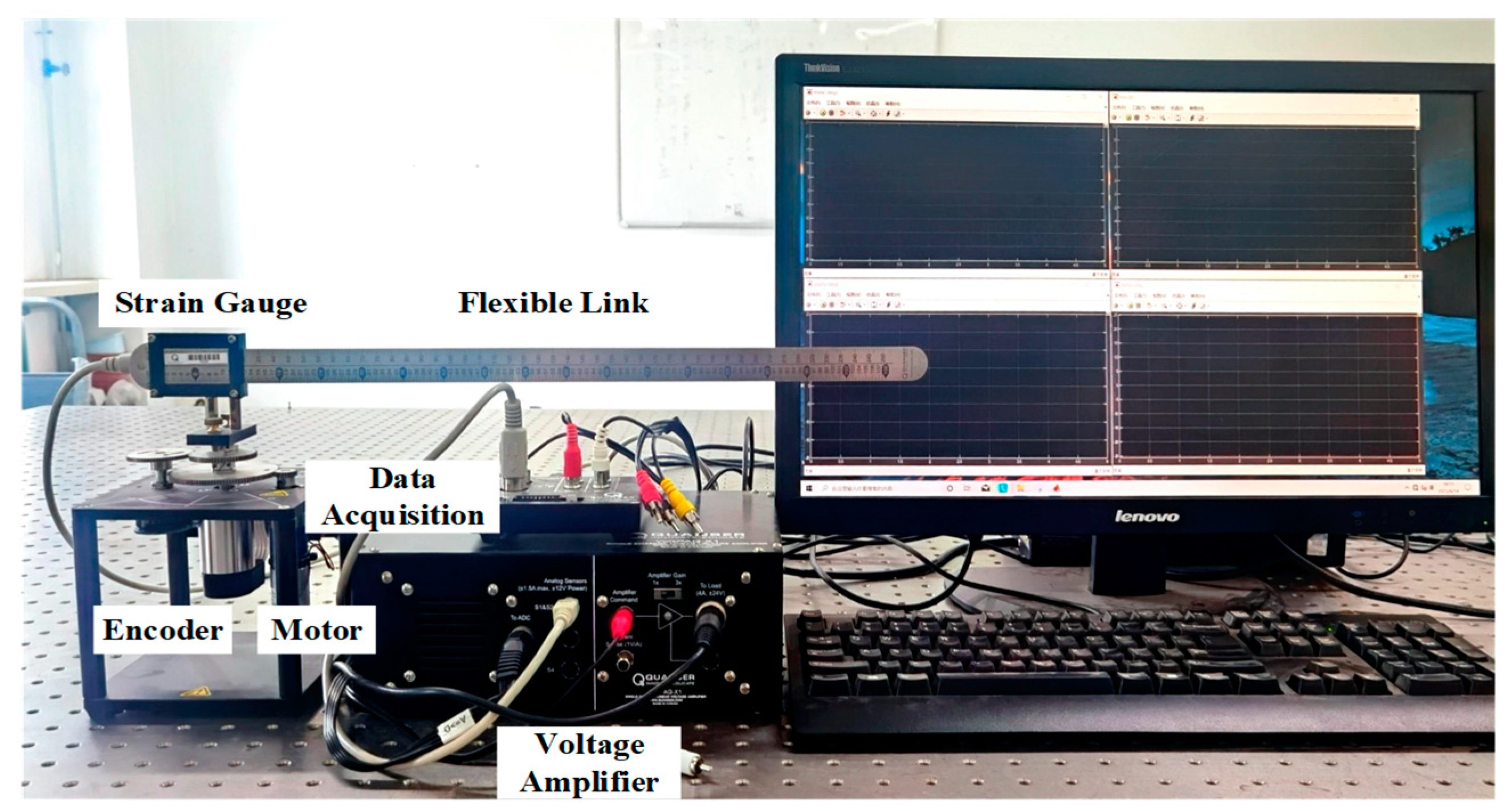
In this paper, the Quanser Flexible Link System is taken as the research object, as shown in Figure 1, and the nominal parameters of the system refer to [24]. The FLM is composed of a servomotor, a set of gears, and a flexible link. The shaft of the servo motor is connected to the gear, and the motor drives the rotation of the flexible link through the gear. Specifically, two sensors are integrated into the system, an encoder with a resolution of 4096 counts/rev, which is used to measure the rotation angle of the system, and a strain gauge with a constant calibration of 1/16.5 rad/V, which is used to measure the deformation of the flexible link.
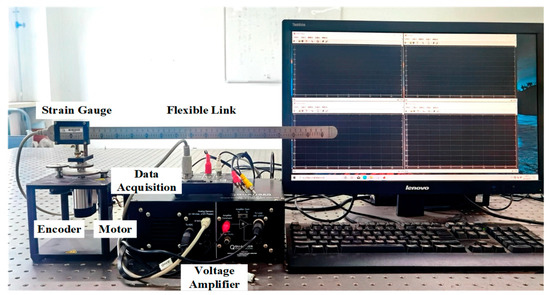
Figure 1.
Experimental platform FLM.
The whole experimental platform consists of an FLM unit, a voltage amplification unit, a data acquisition unit, and a computer. The computer is the core of the experimental platform and is used to implement real-time algorithms. The estimation algorithm and controller run on the computer. The data acquisition unit is used to realize the mutual conversion of analog signals and digital signals in the system. On the one hand, the unit is used to receive feedback information from the FLM, including the encoder angle and the deformation angle of the strain gauge. On the other hand, the unit receives the control signal output from the computer and outputs it to the voltage amplifier unit. The voltage amplifier unit amplifies the control signal to drive the servo motor to realize the rotation and vibration suppression of the FLM.
2.2. Dynamic Model
The schematic diagram of the FLM is shown in Figure 2. The hub angle of the system is , the deformation angle of the flexible link is , (X, Y) is the inertial coordinate system, and (x, y) is the local rotating coordinate system of the rotating center.
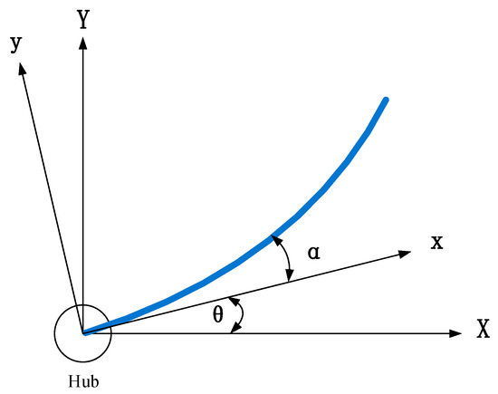
Figure 2.
The schematic diagram of the FLM.
In [24,25], the flexible link is assumed to be a linear spring. The above simplification brings uncertainty to the system dynamics model. Applying the Euler–Lagrange equation, the lumped parameter model of the FLM is obtained as follows:
where is input torque, is viscous friction coefficient, is equivalent moment of inertia, is stiffness of the link, and is link moment of inertia.
The dynamic equation of the FLM in the joint space can be obtained by subtracting (2) from (3) as follows:
The input of the system is the voltage applied to the armature, so the relationship between the torque and the armature voltage is as follows [24,25]:
where is gearbox efficiency, is motor efficiency, is gearbox ratio, is back-emf constant, is motor torque constant, is motor armature resistance, and is armature voltage.
Combining (5) and (4), the system dynamics equation can be written as follows:
where , , , represents system uncertainty and external disturbance.
Remark 1.
Adaptive ESOs are proposed to estimate the system input gain [22,23], and these adaptive ESOs are based on pre-known partial model parameter information. In this paper, the rigid-flexible dynamic parameters and input gain in the system dynamics model are unknown, which means that the existing ESO design method provided by [22,23] is not suitable for the problems proposed here. The primary research goal of this paper is to estimate the rigid-flexible coupling coefficient and input gain of the system by using partial measurement information of the system.
Assumption 1:
The system lumped disturbances , including unmodeled dynamics and external disturbances, is continuously differentiable and bounded. Therefore, its derivative is bounded, satisfying , where is a positive constant.
Assumption 2:
In the FLM system, only the flexible link servo angle and the link deflection angle are measured through the encoder and the strain gauge.
In practical applications, the exact or prior information of physical parameters and cannot be obtained. In order to solve this problem, the parameter is first estimated by an adaptive ESO, which is designed in the following section. Then, according to the estimated system parameters, the system uncertainties and external disturbances are estimated and compensated in real-time using ESO.
3. Control Design
3.1. Adaptive Extended State Observer Design
In this section, an adaptive ESO is proposed to estimate the unknown parameters of the system.
When the system state is represented as , (5) can be rewritten as the following state space form:
In order to accomplish the above design tasks, the unmodeled dynamics and the external disturbance of the system are extended to an additional state variable, which is defined as . Using as the time derivative of , system (6) can be rewritten as follows:
In order to estimate the unknown parameters, an adaptive ESO is designed as follows:
where is the estimated value of and is the estimated value of . is the design parameter, is a positive design parameter, and satisfies the Hurwitz condition. has the following adaptive law:
where is the state estimation error of the observer. is an adjustable parameter.
The state estimation error can be obtained by subtracting (8) from (7):
where is the estimation error of the corresponding parameters.
Theorem 1.
Consider system (7) under Assumptions 1 and 2. The observers given by (9) and (10) can ensure that the estimation error can approach any small value by selecting the appropriate design constant .
Proof.
A new estimation error vector is defined as , ; then, the estimation error dynamics (11) is transformed into the following:
Parameters and are selected such that is Hurwitz. Then, there exists a positive definite matrix satisfying the following Lyapunov equation:
where is a positive definite symmetric matrix.
Remark 2.
In order to reduce the number of parameters to be adjusted in the observer, the characteristic polynomial is selected as , so the parameters of the observer are . Then, can be used to adjust the bandwidth of the adaptive observer (8). The commonly used bandwidth parameterization method is adopted [26].
The following Lyapunov candidate functions are considered:
The time derivative of Equation (13) is as follows:
Because is a constant, is equal to zero at any time; then, . Using [22,23] theorem , (14) can be written as follows:
The appropriate parameters are selected such that , according to Lemma 3.3 in [27], and (15) can be expressed as follows:
We define that , . Then, (16) can be written as follows:
Though Lemma 1 in [28], we know that the system error function converges to
in finite-time , where .
Therefore, for any , the state estimation error and the system parameter estimation error of the adaptive ESO converge to the zero neighborhood in finite-time. □
Remark 3.
From (9), we can see that the value of the adaptive gainsdirectly affects the rapidity of the convergence of the estimated parameters. Increasing the gainswill improve the convergence rate of the estimated parameters. It can be seen from (17) that sufficiently large adaptive gains will reduce the upper bound of the residual. However, in practice, too large adaptive gains will cause an overshoot of the estimated parameters and even cause divergence. Therefore, the selection of the adaptive gainsneeds to consider the rapidity and stability of the estimated parameters.
From (17), we can see that is selected to be sufficiently small and is selected to be sufficiently large, which will reduce the upper bound of the residual error and make the estimation error approach an arbitrarily small value. Among them, increasing can effectively reduce the influence of system uncertainty and external disturbance on parameter estimation. In particular, when there are no system unmodeled dynamics and external disturbances, or its time derivative is zero, and the parameter is set to zero, the observer estimation error can asymptotically converge to zero, that is, , when .
Remark 4.
From (17) and Assumption 1, it can be seen that there is an estimation error of the system parameters through the above adaptive observer, and the estimation error is bounded. Therefore, when the estimated model is adopted, the system estimation error needs to be considered. The new lumped disturbance of the system is defined as , and its derivative is defined as . Because the time derivatives of the variables in the function are bounded, the time derivatives of the variables in the function s are bounded, satisfying , where is a positive number.
3.2. Controller Design Based on an Extended State Observer
In this section, using the above estimates, an ANTSM controller based on ESO is developed to realize the finite-time trajectory tracking of the FLM in the joint space in finite-time and vibration suppression.
3.2.1. Extended State Observer Design and Stability Analysis
According to the estimated values of the model parameters, system (7) can be rewritten as follows:
In order to estimate the system uncertainties and external disturbances, an ESO is designed as follows:
where are adjustable parameters.
From (19) and (20), the dynamic error can be obtained as follows:
We define that . The above formula can be rewritten as a state space form such as follows:
Theorem 2.
Considering the ESO (20), there exist appropriate observer parameters, which satisfy
such that the errors of observer converge to the neighborhood of zero in finite-time.
Proof.
Selecting a candidate Lyapunov function as follows:
The characteristic equation of can be expressed as follows:
where is the Laplace variable and is the three-dimensional unit matrix. The adjustable parameters satisfy
Therefore, is a Hurwitz matrix, and all eigenvalues of have negative real parts. Since is a Hurwitz matrix, there exists a positive definite matrix satisfying the following Lyapunov equation:
where is a positive definite symmetric matrix.
The time derivative of is as follows:
According to (28) and Remark 4, we have
where .
If the condition is satisfied, then
According to Lemma 1 in [29,30], the observer error converges to the set in finite-time . We define that , , and then satisfies
When is selected as the three-dimensional unit matrix, is a function of adjustable parameters, including . Therefore, we can choose the appropriate , satisfying the condition (26), so that the observer error can be reduced to a neighborhood of zero in finite-time. □
3.2.2. Adaptive Nonsingular Terminal Sliding Mode Controller Design and Stability Analysis
The tracking error of the system is defined as follows:
where is the reference trajectory.
Firstly, a nonsingular terminal sliding mode variable is introduced as follows:
where the parameters , need to be designed.
Supposing , the following equivalent control input is generated:
In addition, a reaching control input is introduced:
where , and represent an adaptive switching gain.
Therefore, the controller is designed to be as follows:
The adaptive law of switching gain s is proposed:
where , with the initial integral values satisfying .
Remark 5.
In the joint space, the control of the FLM system will be affected by the flexible deformation and vibration of the link. The vibration of the FLM can be considered as a disturbance, and the ESO can be used for real-time estimation and compensation. Since the flexible vibration is a high-frequency disturbance, the observer needs to use high-bandwidth parameters, which will bring high-frequency noise into the system. Therefore, in the proposed controller (36), the deformation dynamic term is introduced to reduce the high bandwidth of the observer and effectively suppress the vibration.
The stability analysis of the ANTSM controller based on the ESO is shown below.
Theorem 3.
Considering the system (19), if the ANTSM controller is designed by (36) with sliding mode variable (33), the tracking error and the first derivative of the tracking error converge to a small neighborhood of zero in finite-time.
Proof.
A Lyapunov function is chosen as follows:
where .
According to the controller (36), the differential of is calculated as follows:
Letting denote the lumped residuals of the system, satisfying , and denote the upper bounds of the observer estimation error and the flexible dynamics, (39) can be written as follows:
According to Lemma 3.3 in [27], (40) can be expressed as follows:
We define that . Then, (39) can be expressed as follows:
Substituting (36) into (19), if and , we have . Then, is not an attractor in the reaching phase.
According to Lemma 1 in [28], the sliding mode variable s will satisfy
where . Then,
in finite-time
According to [31], the tracking error and the first derivative of the tracking error eventually converge to the region
The proof is complete. □
4. Simulation and Experimental Verification
In this section, in order to verify the effectiveness of the proposed adaptive ESO and the adaptive sliding mode controller based on the ESO, numerical simulation and physical experiments are carried out on the Quanser Flexible Link System, as shown in Figure 2. Then, according to the nominal parameters of [24], the state space equation of the system is calculated as follows:
4.1. Estimation of Unknown Parameters of the System
The unknown parameters of the system are estimated by numerical simulation to verify the convergence of the proposed observer. The control input is set to a square wave signal with an amplitude of 1 V and a frequency of 1 Hz.
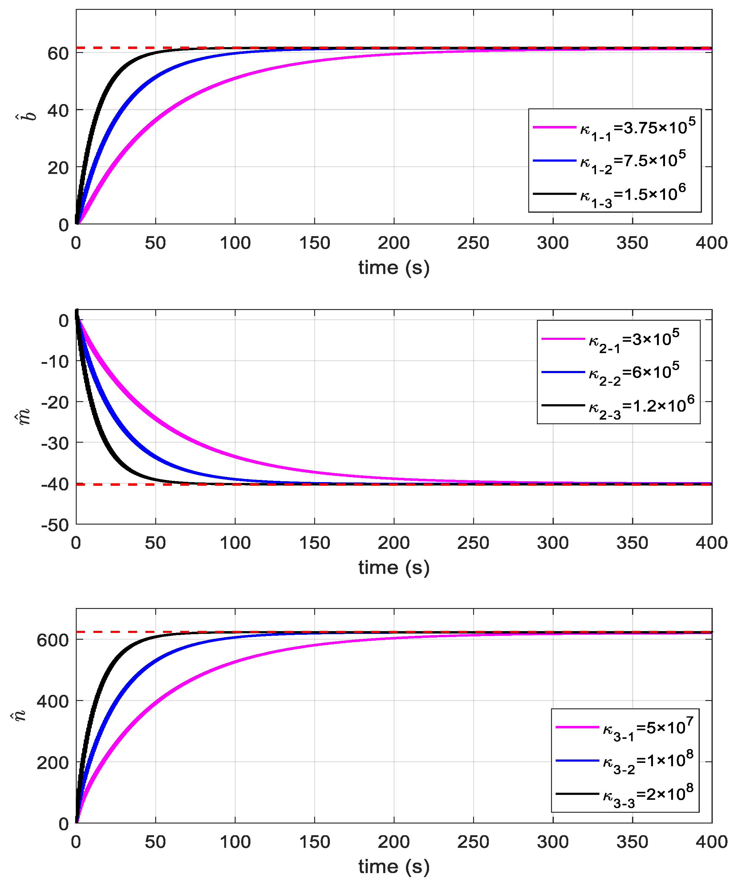
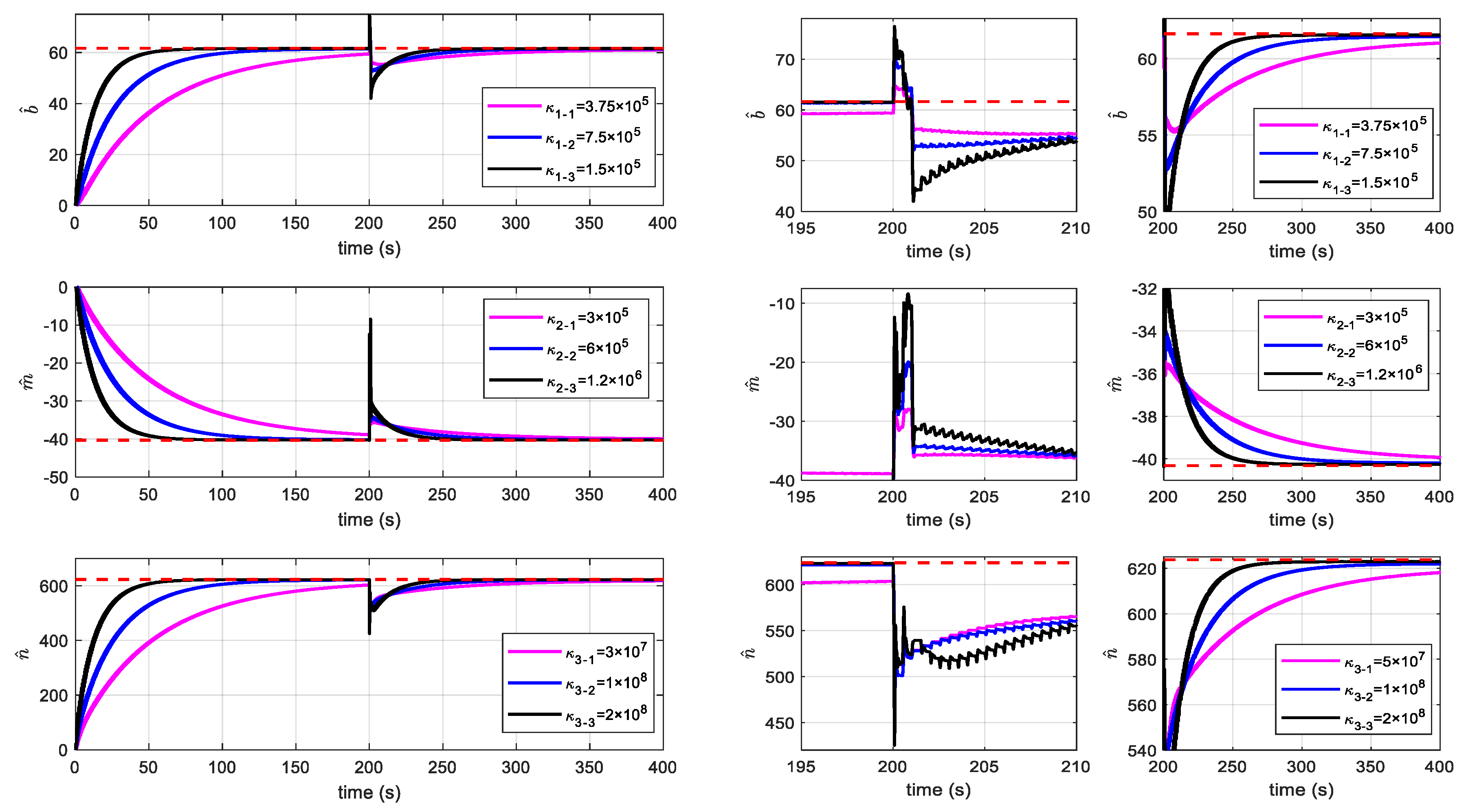
Three different sets of adaptive gains are selected to illustrate the effect of adaptive gains on parameter estimation. The initial value of the model parameter is set to . Three groups of different adaptive gains are set to , , and respectively. The bandwidth is selected as , and are set to a small positive number . Figure 3 shows that the proposed adaptive ESO can achieve an accurate estimation of model parameters under different adaptive gains. The results indicate that the larger the adaptive gain, the faster the parameter convergence. Moreover, pulses with an amplitude of 2 V and width of 1 s are added to the control input at 200 s to simulate the scene of impact disturbance. Figure 4 shows that the larger the adaptive gain, the more susceptible the parameter estimation is to the impact of disturbance. However, when the impact disturbance disappears, the parameter converges faster.
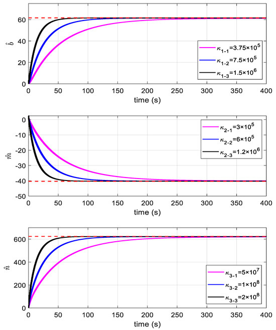
Figure 3.
Estimation results of unknown parameters of the system under different adaptive law gains. (The red dashed lines represents the nominal value of the corresponding parameter.)
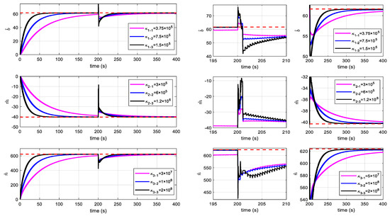
Figure 4.
Estimation results of unknown parameters of the system with impact disturbance under different adaptive law gains. (The red dashed lines represents the nominal value of the corresponding parameter.)
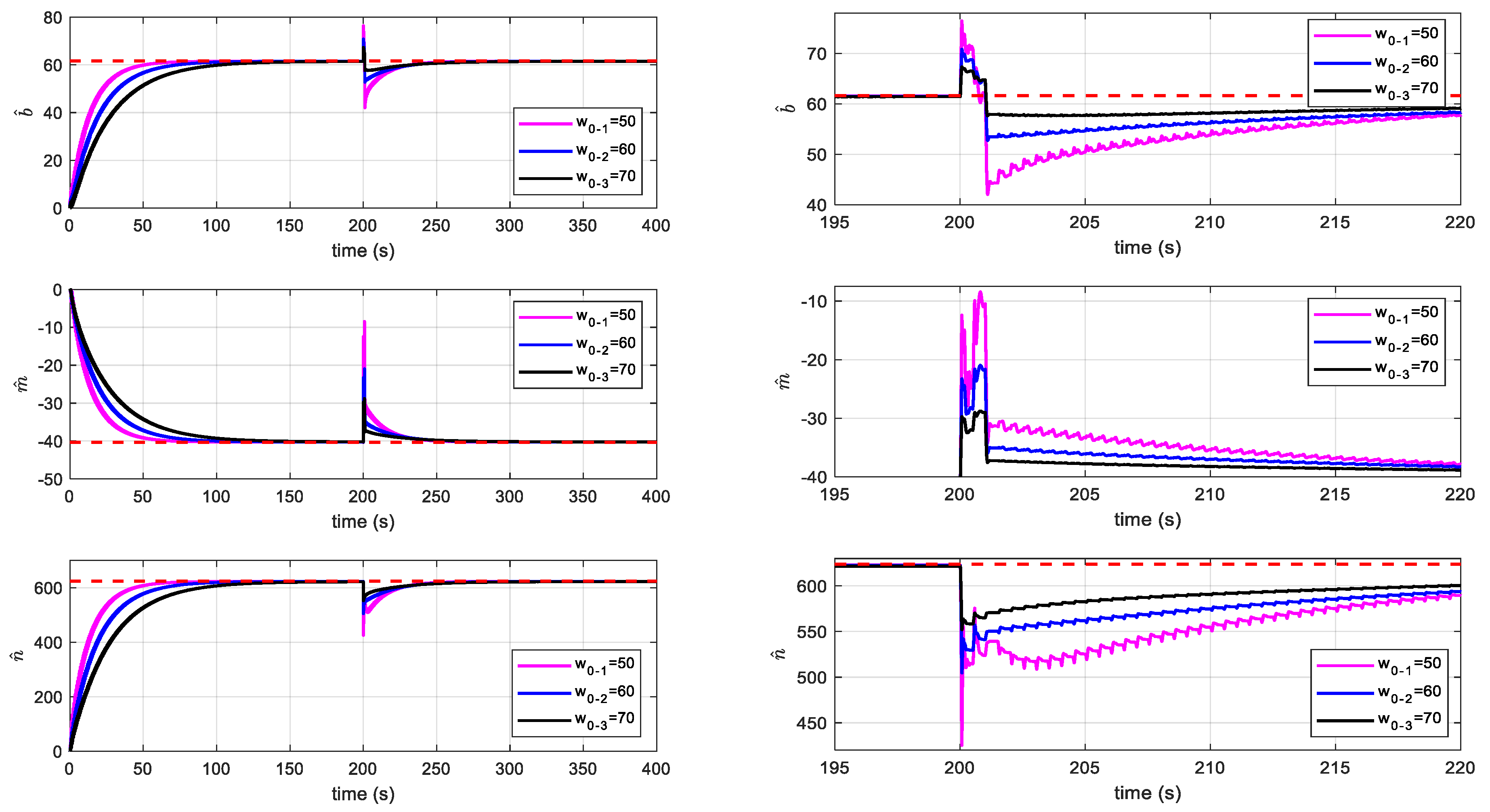
Three different bandwidths are selected to illustrate the influence of bandwidth on parameter estimation. The initial value of the model parameters is set to , and the parameters of the adaptive ESO are selected to be . The bandwidth is set to . Figure 5 shows that the adaptive ESO with large bandwidth can effectively reduce the influence of external disturbance on parameter estimation.
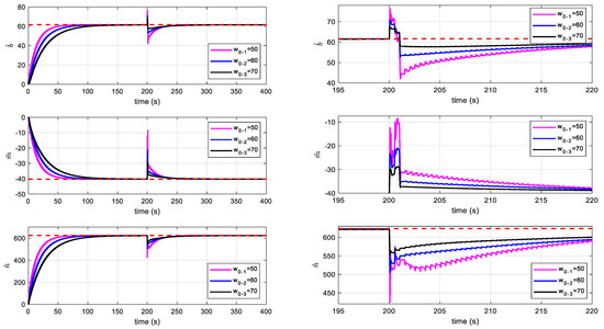
Figure 5.
The estimation results of the unknown parameters of the system with impact disturbance under different bandwidths. (The red dashed lines represents the nominal value of the corresponding parameter.)
From the curves shown in Figure 4 and Figure 5, we can see that when the system is affected by external disturbances, the parameter estimates of the adaptive ESO are out of equilibrium and fluctuate during the convergence process. This is because when the system is affected by external disturbances, the state estimation error of the adaptive ESO is out of the equilibrium point. At the same time, the control input is a square-wave signal, and the state estimation error changes with the control input, causing the parameter estimation to fluctuate. The fluctuation amplitude is affected by the adaptive gains, and the larger the gains, the larger the fluctuation. As the state estimation error returns to equilibrium, the parameter estimation fluctuation disappears.
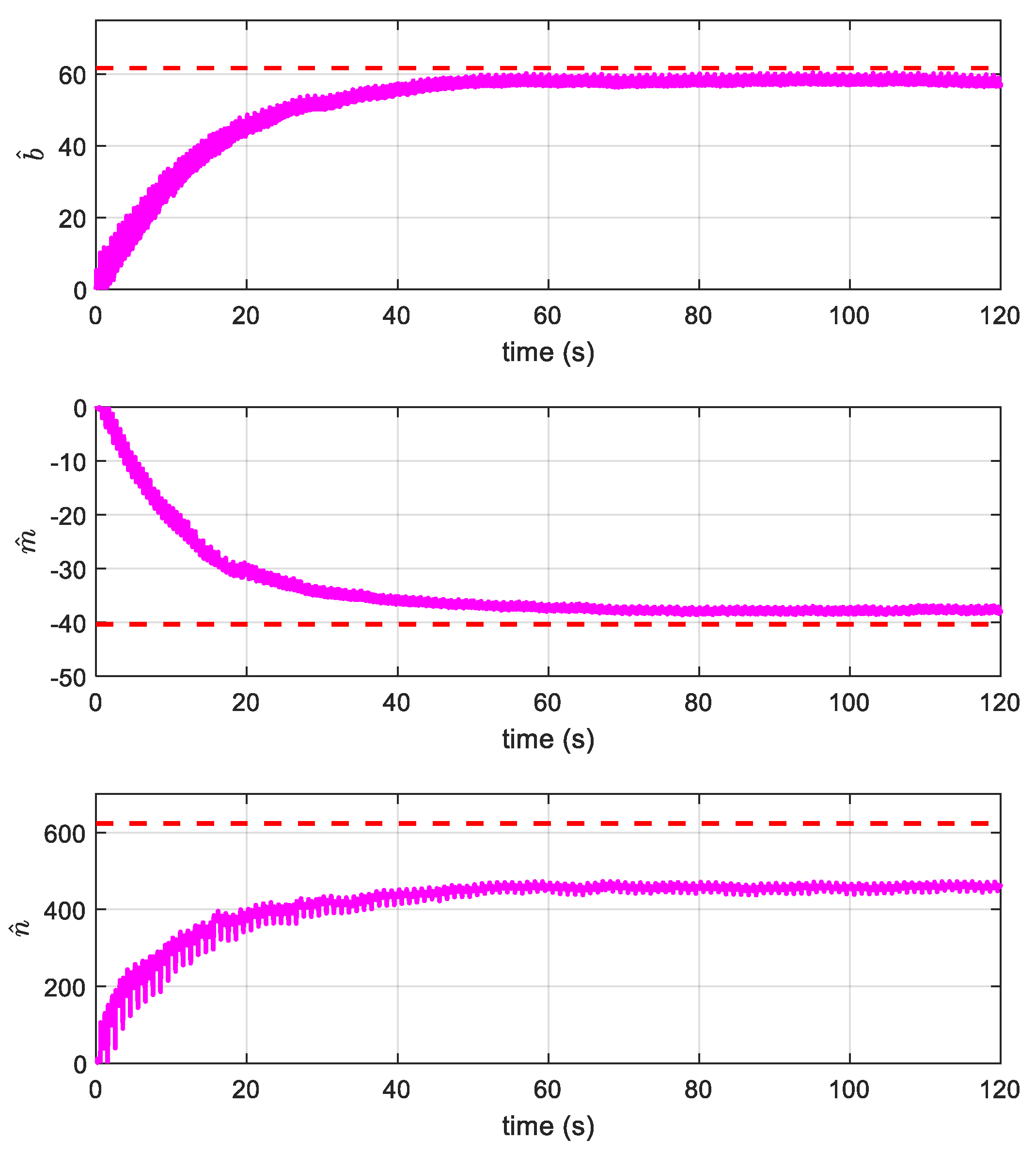
Finally, the parameter estimation of the system is carried out in the actual system. Figure 6 shows the parameter estimates, , , , respectively. The above experimental results are close to the nominal values. The difference between the two is caused by the following reasons: the error between the nominal parameters and the parameters of the actual system, the high-order dynamics of the flexible link neglected in the dynamic model, the friction existing in the actual system, and the measurement accuracy of the sensor and other factors. is the estimated coefficient related to the deformation angle of the flexible link, which is significantly different from its nominal value. This is because the flexible link is equivalent to a linear spring in the lumped parameter model, and the viscous damping coefficient of the link is ignored. Due to this simplified method, the lumped parameter model cannot accurately reflect the true deflection angle of the flexible link. In [25], the shortcomings of the lumped parameter model were verified by experiments in both the frequency domain and the time domain. Although there is a certain error between the parameter estimates and the nominal values, the results provide an important design basis for the controller design, especially the system input gain.
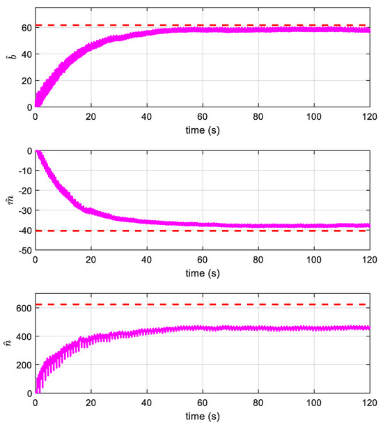
Figure 6.
Estimated results of an actual system. (The red dashed lines represents the nominal value of the corresponding parameter.)
4.2. Tracking and Anti-Disturbance Performance
Moreover, in order to verify the developed controller, the following two controllers, LQR and adaptive sliding mode (ASM) [28], are compared. The LQR controller is expressed as , and ASM [28] is designed as , where . These three controller parameter values are shown in Table 1.

Table 1.
Parameters of three different control methods.
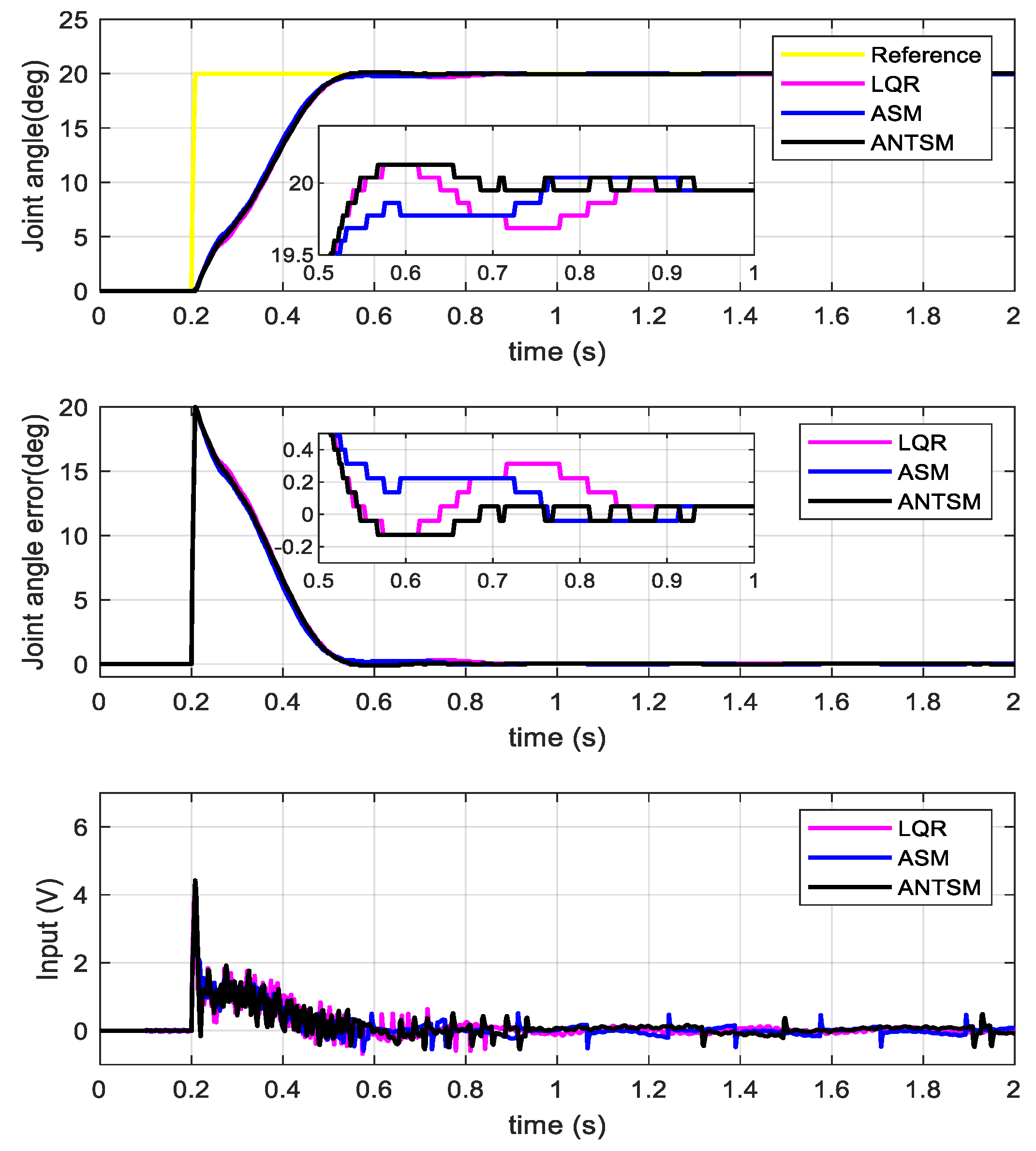
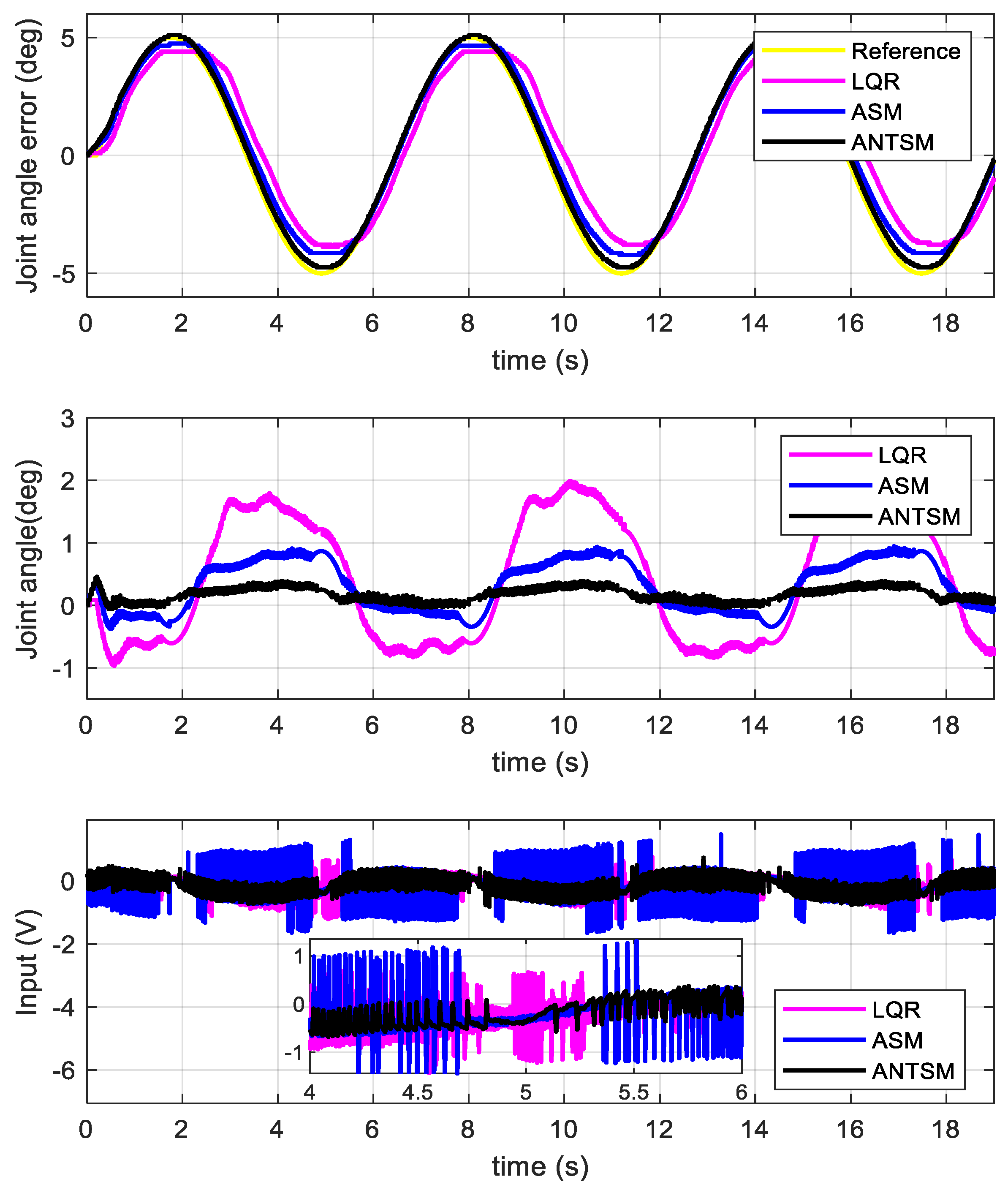
Firstly, a step curve with an amplitude of 20° and a sine curve with an amplitude of 5° and a frequency of 0.16 Hz are applied to evaluate the tracking performance of the three controllers. Figure 7 and Figure 8 show the step and sinusoidal responses of the three controllers.
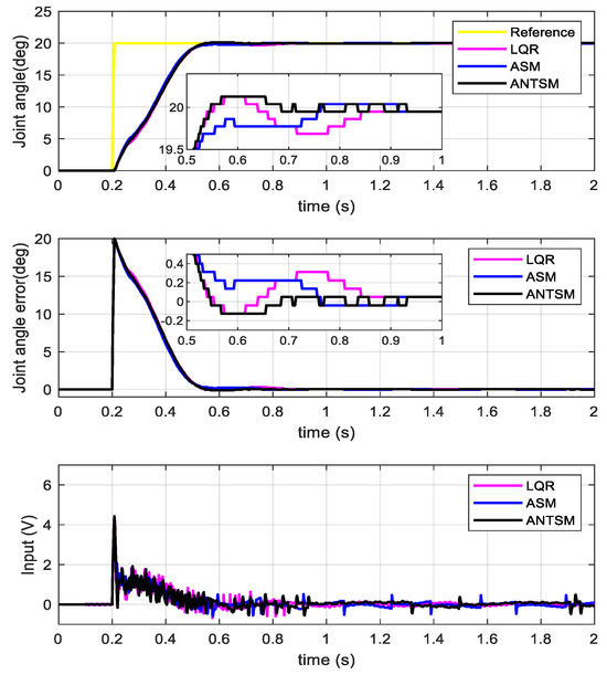
Figure 7.
Step response curve of the three controllers.

Figure 8.
Sinusoidal response curve of the three controllers.
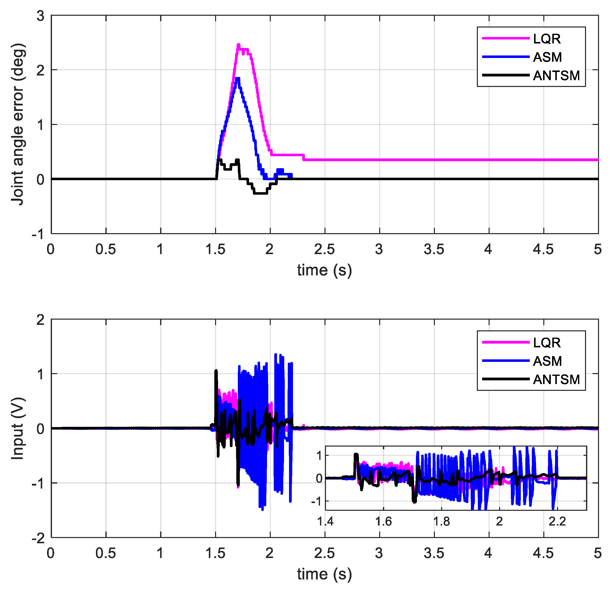
In order to evaluate the anti-disturbance performance of the three controllers, the system is pointed at 0°, and an interference pulse with an amplitude of 1 V and a width of 0.2 s is added at 1.5 s of the control input, which is used to simulate the impact scene of the system. Figure 9 shows the anti-disturbance of the three controllers.

Figure 9.
Anti-disturbance response curve of the three controllers.
Based on the above experimental results, the performance parameters of the system are shown in Table 2. First, it can be seen that the step response time of the three controllers is 0.65 s, 0.55 s, and 0.49 s, respectively. The ANTSM controller based on an ESO has a shorter response time than the other two controllers. Then, the data show that the maximum sinusoidal tracking errors of the three controllers are 2°, 1°, and 0.4°, respectively. Therefore, the finite-time sliding mode controller based on the ESO has the best tracking performance. Finally, we can see that the anti-disturbance errors of the three controllers are 2.4°, 1.8°, and 0.6°, respectively. The above values show that in terms of anti-disturbance, the proposed controller has a stronger anti-disturbance ability than the other two controllers. Furthermore, it can be seen from the voltage curves in Figure 8 and Figure 9 that the control inputs of the three controllers have different degrees of oscillation. However, the oscillation amplitude of the control voltage of the proposed controller is significantly smaller than that of the other controllers. In summary, the proposed controller has a better transient response, tracking performance, and disturbance rejection ability and can effectively attenuate the oscillation of the traditional controller.
Table 2.
Performance of three different control methods.
5. Conclusions
The research results of this paper prove the effectiveness of the model parameter estimation method based on an adaptive ESO and the ANTSM control strategy based on an ESO applied to FLM. The adaptive ESO can effectively estimate the unknown system parameters of the FLM, including the rigid-flexible coupling coefficient and the control input gain. In addition, the ANTSM control strategy based on an ESO achieves faster, more accurate, and more perturbation-resistant trajectory tracking and vibration suppression of the FLM without requiring prior knowledge of system uncertainty and external disturbances.
For similar flexible systems, the estimation method can obtain the unknown parameters of the system according to the feedback information. At the same time, the proposed controller can estimate and compensate for dynamic uncertainties and external disturbances, such as friction, in real-time, so as to improve the tracking accuracy and anti-disturbance ability of the system. Furthermore, the finite-time convergence characteristics of the proposed controller can improve the transient response of the system. However, in practical applications, the premise of the parameter estimation method is that the model form of the system is known. Therefore, before estimating the parameters, it is necessary to carry out a dynamic analysis and obtain the dynamic model.
In the future, the system model parameters will be time-varying for the scenarios where FLM grabs and drops different targets. We intend to take this problem as a future research topic and design a control method with stronger environmental adaptability for FLM. The adaptive sliding mode control method based on online parameter estimation to achieve robust control of FLM with time-varying parameters is a challenging task.
Author Contributions
Methodology, F.J. and C.M.; Software, F.J.; Validation, F.J.; Formal analysis, F.J.; Investigation, F.J.; Data curation, F.J. and F.W.; Writing—original draft, F.J.; Writing—review & editing, F.W., Y.C. and X.F.; Project administration, M.X. All authors have read and agreed to the published version of the manuscript.
Funding
This research received no external funding.
Institutional Review Board Statement
Not applicable.
Informed Consent Statement
Not applicable.
Data Availability Statement
The data presented in this study are available on request from the corresponding author. The data are not publicly available due to privacy.
Conflicts of Interest
The authors declare no conflict of interest.
References
- He, W.; Gao, H.; Zhou, C.; Yang, C.; Li, Z. Reinforcement Learning Control of a Flexible Two-Link Manipulator: An Experimental Investigation. IEEE Trans. Syst. Man Cybern. Syst. 2021, 51, 7326–7336. [Google Scholar] [CrossRef]
- Gao, H.; He, W.; Zhou, C.; Sun, C. Neural Network Control of a Two-Link Flexible Robotic Manipulator Using Assumed Mode Method. IEEE Trans. Ind. Inform. 2019, 15, 755–765. [Google Scholar] [CrossRef]
- Rahmani, B.; Belkheiri, M. Adaptive neural network output feedback control for flexible multi-link robotic manipulators. Int. J. Control. 2019, 92, 2324–2338. [Google Scholar] [CrossRef]
- Sun, C.; He, W.; Hong, J. Neural Network Control of a Flexible Robotic Manipulator Using the Lumped Spring-Mass Model. IEEE Trans. Syst. Man Cybern. Syst. 2017, 47, 1863–1874. [Google Scholar] [CrossRef]
- Xu, B. Composite Learning Control of Flexible-Link Manipulator Using NN and DOB. IEEE Trans. Syst. Man Cybern. Syst. 2018, 48, 1979–1985. [Google Scholar] [CrossRef]
- Yang, C.; Xu, Y.; Zhou, L.; Sun, Y. Model-Free Composite Control of Flexible Manipulators Based on Adaptive Dynamic Programming. Complexity 2018, 2018, 9720309. [Google Scholar] [CrossRef]
- Liu, Z.; Liu, J. Adaptive Iterative Learning Boundary Control of a Flexible Manipulator with Guaranteed Transient Performance. Asian J. Control 2018, 20, 1027–1038. [Google Scholar] [CrossRef]
- Yang, X.; Ge, S.S.; He, W. Dynamic modelling and adaptive robust tracking control of a space robot with two-link flexible manipulators under unknown disturbances. Int. J. Control 2018, 91, 969–988. [Google Scholar] [CrossRef]
- Xu, B.; Zhang, P. Composite Learning Sliding Mode Control of Flexible-Link Manipulator. Complexity 2017, 2017, 9430259. [Google Scholar] [CrossRef]
- Long, T.; Li, E.; Hu, Y.; Yang, L.; Fan, J.; Liang, Z.; Guo, R. A Vibration Control Method for Hybrid-Structured Flexible Manipulator Based on Sliding Mode Control and Reinforcement Learning. IEEE Trans. Neural Netw. Learn. Syst. 2021, 32, 841–852. [Google Scholar] [CrossRef]
- Sanz, A.; Etxebarria, V. Experimental Control of a Two-Dof Flexible Robot Manipulator by Optimal and Sliding Methods. J. Intell. Robot. Syst. 2006, 46, 95–110. [Google Scholar] [CrossRef]
- Shang, D.; Li, X.; Yin, M.; Li, F. Tracking control strategy for space flexible manipulator considering nonlinear friction torque based on adaptive fuzzy compensation sliding mode controller. Adv. Space Res. 2023, 71, 3661–3680. [Google Scholar] [CrossRef]
- Tang, Y.; Sun, F.; Sun, Z. Neural network control of flexible-link manipulators using sliding mode. Neurocomputing 2006, 70, 288–295. [Google Scholar] [CrossRef]
- Sahu, U.K.; Subudhi, B.; Patra, D. Sampled-data extended state observer-based backstepping control of two-link flexible manipulator. Trans. Inst. Meas. Control 2019, 41, 3581–3599. [Google Scholar] [CrossRef]
- Fareh, R.; Al-Shabi, M.; Bettayeb, M.; Ghommam, J. Robust Active Disturbance Rejection Control for Flexible Link Manipulator. Robotica 2020, 38, 118–135. [Google Scholar] [CrossRef]
- Astorga-Zaragoza, C.M.; Zavala-Río, A.; Alvarado, V.M.; Méndez, R.M.; Reyes-Reyes, J. Performance monitoring of heat exchangers via adaptive observers. Measurement 2007, 40, 392–405. [Google Scholar] [CrossRef]
- Besançon, G. Remarks on nonlinear adaptive observer design. Syst. Control Lett. 2000, 41, 271–280. [Google Scholar] [CrossRef]
- Bowong, S.; Kakmeni, F.M.; Fotsin, H. A new adaptive observer-based synchronization scheme for private communication. Phys. Lett. A 2006, 355, 193–201. [Google Scholar] [CrossRef]
- Cho, Y.M.; Rajamani, R. A systematic approach to adaptive observer synthesis for nonlinear systems. IEEE Trans. Autom. Control 1997, 42, 534–537. [Google Scholar]
- Yue, J.; Liu, L.; Peng, Z.; Wang, D.; Li, T. Data-driven adaptive extended state observer design for autonomous surface vehicles with unknown input gains based on concurrent learning. Neurocomputing 2022, 467, 337–347. [Google Scholar] [CrossRef]
- Peng, Z.; Liu, L.; Wang, J. Output-Feedback Flocking Control of Multiple Autonomous Surface Vehicles Based on Data-Driven Adaptive Extended State Observers. IEEE Trans. Cybern. 2021, 51, 4611–4622. [Google Scholar] [CrossRef] [PubMed]
- Liu, Z. Adaptive extended state observer based heading control for surface ships associated with sideslip compensation. Appl. Ocean Res. 2021, 110, 102605. [Google Scholar] [CrossRef]
- Jing, C.; Xu, H.; Song, X.; Lu, B. Adaptive extended state observer-based flatness nonlinear output control for torque tracking of electrohydraulic loading system. Trans. Inst. Meas. Control 2017, 40, 2999–3009. [Google Scholar] [CrossRef]
- Silva, B.P.; Santana, B.A.; Santos, T.L.; Martins, M.A. An implementable stabilizing model predictive controller applied to a rotary flexible link: An experimental case study. Control Eng. Pract. 2020, 99, 104396. [Google Scholar] [CrossRef]
- Altıner, B.; Delibaşı, A.; Erol, B. Modeling and control of flexible link manipulators for unmodeled dynamics effect. Proc. Inst. Mech. Eng. Part I: J. Syst. Control Eng. 2018, 233, 245–263. [Google Scholar] [CrossRef]
- Gao, Z. Scaling and Bandwidth-Parameterization Based Controller Tuning. In Proceedings of the 2003 American Control Conference, Denver, CO, USA, 4–6 June 2003. [Google Scholar]
- Zuo, Z.; Tie, L. A new class of finite-time nonlinear consensus protocols for multi-agent systems. Int. J. Control 2014, 87, 363–370. [Google Scholar] [CrossRef]
- Shao, K.; Tang, R.; Xu, F.; Wang, X.; Zheng, J. Adaptive sliding mode control for uncertain Euler–Lagrange systems with input saturation. J. Frankl. Inst. 2021, 358, 8356–8376. [Google Scholar] [CrossRef]
- Ali, N.; Tawiah, I.; Zhang, W. Finite-time extended state observer based nonsingular fast terminal sliding mode control of autonomous underwater vehicles. Ocean Eng. 2020, 218, 108179. [Google Scholar] [CrossRef]
- Razmjooei, H.; Palli, G.; Janabi-Sharifi, F.; Alirezaee, S. Adaptive fast-finite-time extended state observer design for uncertain electro-hydraulic systems. Eur. J. Control 2023, 69, 100749. [Google Scholar] [CrossRef]
- Sun, L.; Liu, Y. Extended state observer augmented finite-time trajectory tracking control of uncertain mechanical systems. Mech. Syst. Signal Process. 2010, 139, 106374. [Google Scholar] [CrossRef]

Disclaimer/Publisher’s Note: The statements, opinions and data contained in all publications are solely those of the individual author(s) and contributor(s) and not of MDPI and/or the editor(s). MDPI and/or the editor(s) disclaim responsibility for any injury to people or property resulting from any ideas, methods, instructions or products referred to in the content. |
© 2023 by the authors. Licensee MDPI, Basel, Switzerland. This article is an open access article distributed under the terms and conditions of the Creative Commons Attribution (CC BY) license (https://creativecommons.org/licenses/by/4.0/).