Abstract
In order to effectively control the stability of surrounding rock in ultra-large span open-off cuts by employing the techniques of support strength theory calculations and analogical application methods, two sets of rational support schemes were proposed, and the optimal design of active support parameters in thick coal seams with ultra-large span open-off cuts was explored by using theoretical analysis, numerical simulation, and field experiments. The results demonstrated that the span is one of the key factors influencing the stability of the roadway roof, exhibiting an inverse quadratic relationship with the peak stress borne by the roadway roof. By utilizing the pre-stressing force of anchor cables and support strength formulas, two sets of active support schemes for controlling the surrounding rock in thick coal seams with ultra-large span open-off cuts were established, and an optimized support scheme was obtained through numerical simulation. These findings provide references and guidance for related mining engineering under actual conditions in mines.
1. Introduction
With the development and utilization of ultra-large-scale coal mining machinery, the shearer and hydraulic supports are becoming increasingly larger. The underground coal mining is moving towards mechanization and unmanned operation [1]. In order to accommodate large modern machinery, the size of the entry section of the working face is gradually increasing, and the size of some open-off cuts exceeds 10 m [2,3,4]. Therefore, it is of great significance to study the surrounding rock failure status and control techniques of cuts in thick coal seams with ultra-large spans.
In thick coal seam conditions, cutting areas are typically located within the coal seam itself, and their width is much larger than conventional roadway dimensions. Inadequate support parameters can jeopardize the stability of the surrounding strata in the cutting areas, severely impacting the normal progress of mining operations and the safety of underground personnel and mining equipment [5,6].
Regarding the support of ultra-large span open-off cuts, many researchers have made significant progress and achieved preliminary results. Chi G.M. et al. [7] investigated the control methods for the surrounding rock in ultra-large cutting areas in the Bu Lianta coal mine. They demonstrated that segmented support and hydraulic pre-splitting for roof control contribute to maintaining the stability of the roadway, providing valuable insights into deformation control for cutting areas. Ping Z. et al. [8] researched the impact of support structure instability on roadways in high-stress fractured strata and proposed a combined support technology based on the failure principles of anchor rod support, addressing the support challenges in high-stress fractured strata roadways. Wang H.W. et al. [9] studied the “anchor rod + short anchor cable + long anchor cable + steel shed” active-passive combined support method for a 5.5 m thick ultra-large span open-off cutting area in Zhaojiazhai, providing guidance for support in roadways with weak interlayers. He F.L. et al. [10], to address the control challenges in thick coal seam roofs and ultra-large span open-off cutting areas, used numerical simulation to analyze the influence of roof thickness and cutting areas width on surrounding rock failure characteristics and proposed a “cross-step” joint control technology. Xu Z.J. et al. [11] conducted theoretical analysis, numerical simulation, and field measurements to analyze stress distribution characteristics in roadways and deformation failure characteristics of surrounding rock, proposing a high pre-stressed roof beam high-strength double-anchor truss support system. Chai J. et al. [12], through theoretical analysis, numerical simulation, and field practice, analyzed the deformation and failure characteristics of large span open-off cutting areas, proposing and implementing a support method of “short, dense anchor cables + suspended anchor rods” that achieved good support results. Xie Z.Z. et al. [13,14] conducted comprehensive experiments using a pneumatic loading system to compare and study the control effects of three support systems on coal–rock composite roof roadways, offering insights into rapid excavation stability in deep mines and proposing a new support system. Liu Jianyu et al. [15] studied the comprehensive control technology for ultra-large span open-off cutting areas under complex technical conditions. The results showed that the application of this technology is safe and reliable, ensuring the stability of surrounding strata in cutting areas. Hu Y.R. et al. [16] addressed the challenges of large-span open-off cutting area support by conducting numerical simulation analysis of cutting area stress and plastic zone distribution, proposing a new long-short cable joint support scheme. Zhou Bo et al. [17] established a three-directional load-bearing beam structural analysis model for roadway roofs, determined stress analysis methods for beam structures under three-directional stress, and obtained the failure patterns under three-directional stress for open-off cutting areas.
While these studies have primarily focused on ultra-large spans or thick coal seams, research on support in ultra-large span open-off cutting areas in thick coal seams is relatively limited. Moreover, due to the diverse and complex mining environments, support solutions developed for one mine may not be entirely applicable to others. Therefore, this paper, based on the context of open-off cutting areas in the 81309 working face of Baode Coal Mine, explores strategies for controlling the surrounding rock in open-off cutting areas with thick coal seams and large spans. By analyzing the relationship between span and roof stability in thick coal seams, studying the influence of different active support parameters on roadway strata stability, and designing active support parameter schemes for cutting areas in Baode Coal Mine, this research aims to guide practical production work and holds significant engineering significance.
2. Stability Analysis of Ultra-Large Span Open-Off Cutting Areas
2.1. Engineering Background
The Baode Coal Mine is located within the jurisdiction of Qiaotou Town, Baode County, Shanxi Province. Figure 1 shows the schematic diagram of the traffic location of Baode Coal Mine, where the situ investigation was performed. The 81309 working face is situated west of the 81308 working face, with the southern boundary being the mining field boundary and the western boundary representing unmined coal seams. The coal rock layers exhibit a predominantly north–south orientation and are characterized by a westward dipping monocline structure, with coal seam dip angles averaging around 5°.
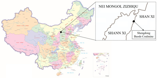
Figure 1.
The location of Baode Coal Mine.
The coal seam thickness in the cutting section of the 81309 working face ranges from 5 to 8 m, with an average thickness of 7.1 m. The coal seam exhibits a complex structure with multiple interlayers of gangue, including 2–3 stable gangue layers. The rock types present include mudstone and carbonaceous mudstone. The immediate roof of the cutting section coal seam is composed of coarse-grained sandstone, with a thickness of 3.7 m, while the overlying stratum is characterized by medium-grained sandstone, with a thickness of 9.8 m. The immediate floor directly beneath the coal seam consists of fine-grained sandstone with an approximate thickness of 2.1 m. The coal seam pillar configuration is illustrated in Figure 2.
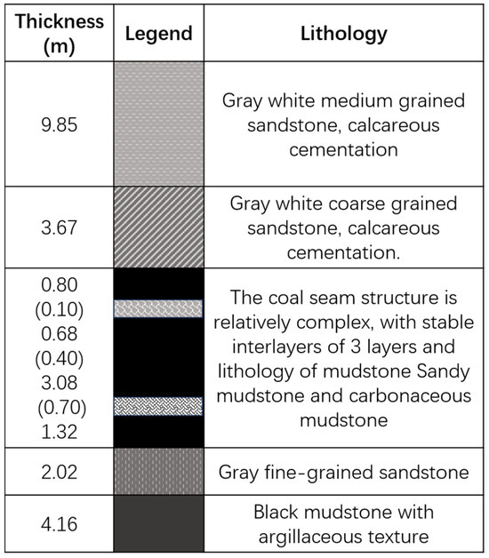
Figure 2.
Coal seam histogram.
The width of the cutting section in the 81308 working face is approximately 8.8 m. However, for the upcoming excavation of the 81309 working face, the cutting section width will be increased to 9.8 m, with a height of 3.8 m. The maximum span of the roadway at the location where the chamber is installed in the cutting area is 11.8 m. The substantial increase in the cutting width for the 81309 working face necessitates a reevaluation of the support parameters for cutting section support, as adhering to the original support plan designed for the 81308 working face would pose challenges in ensuring effective cutting section support for the 81309 working face.
2.2. Analysis of Factors Influencing Stability in the Open-Off Cutting Areas
The 81309 working face at Baode Coal Mine is characterized as a large-scale, high-cut, comprehensive mining operation with pronounced susceptibility to the influence of substantial mechanical equipment. The design parameters specify a net width of 9.8 m at the cutting location, and an exceptional feature of this working face is the maximum span of the roadway, which reaches 11.8 m at the cutting installation chamber. The instability phenomenon is easy to occur in the middle of the roof of the roadway with such a large span. The thickness of the coal seam in the position of cutting holes fluctuates greatly, the roof structure is complicated, the coal seam contains many dirt layers, and the surrounding rock of the roadway is broken and difficult to support. Baode Coal Mine mining alternating work is relatively perfect; during the 81308 mining face, 81309 working roadway has completed the excavation work, and the service cycle of cutting the hole is as long as two years, further aggravating the difficulty of roadway support.
In light of the comprehensive analysis provided, it is evident that the stability control of the cutting area in the 81309 working face is influenced by multiple factors, with the significant impact of the expansive open-off cutting span being particularly prominent. Notably, certain sections of the excavation exhibit span up to 11.8 m, thereby presenting formidable challenges in terms of maintenance. The pronounced subsidence of the mid-section of the roadway roof, coupled with the inadequacy of the existing support strength, underscores the imperative need to explore effective methodologies for actively supporting the surrounding rock in ultra-large-span cutting areas to ensure the safety and integrity of mining operations within the coal mine.
2.3. Cutting Span and Stability of Working Face
- (1)
- Mechanical Model
The relationship between the span of open-off cuts and the stability of the roof is a significant factor. To investigate this relationship, a theoretical model for analyzing the stress characteristics of open-off cuts was established. In this model, the open-off cut is treated as infinitely long, with no influence on the stability of the roof. Based on principles from elasticity theory, a theoretical model with fixed supports at both ends was developed, as shown in Figure 3.
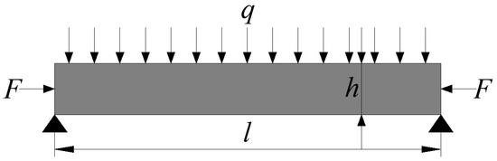
Figure 3.
Theoretical model of stress on open-off cuts.
In the figure, h (m) corresponds to the height of the roadway, l (m) is the span, the upper portion of the roof is subjected to a uniformly distributed load q (Pa), and the horizontal support force is F (Pa).
According to the mechanical model, the relationship between the span of open-off cuts and the stability of the working face was analyzed. The critical stress when both ends are fixed is:
where i represents the ratio of the open-off cut span to the thickness of the roof rock layer, known as the span-to-thickness ratio. From the equation, it can be observed that the critical stress for the model’s stability is inversely proportional to the square of the span-to-thickness ratio. It is directly related to the elastic modulus and dependent on the Poisson’s ratio but unrelated to the rock strength. This suggests that, under constant roof rock layer thickness, the span of the open-off cut and the mechanical properties of the rock layer are the determining factors for roof stability. As the span of open-off cuts in roadway excavation is twice that of conventional mining tunnels, the ratio of the critical stress-bearing capacity of the roof in open-off cuts to conventional tunnels is only one-fourth, indicating reduced roof stability in open-off cuts.
- (2)
- Conditions for fracture instability
Due to the lower tensile strength of the rock layer, under significant in situ stress, it is highly likely that the rock beam may crack at the upper ends of the supports and then fracture near the middle or bottom of the beam. As the rock blocks rotate, horizontal compressive forces are formed, resulting in a three-hinge arch-shaped equilibrium. However, it is important to note that rock beams do not necessarily collapse as soon as they reach the fracture limit. The arching conditions primarily depend on the original rock stress and the magnitude of horizontal compressive forces formed during rock block rotation. When the horizontal compressive forces are sufficiently high, multiple rock blocks can still remain compressed together in a suspended state.
The conditions for sliding instability of the structure involve the magnitude of the frictional force at the interlocking point, which is the product of the horizontal compressive force and the coefficient of friction at that point. This force acts in the opposite direction to the direction of rock block sliding, serving to prevent the mutual sliding of rock blocks.
When the shear force exceeds the frictional force, the structure experiences instability, thus the conditions of instability, as shown in Figure 4.
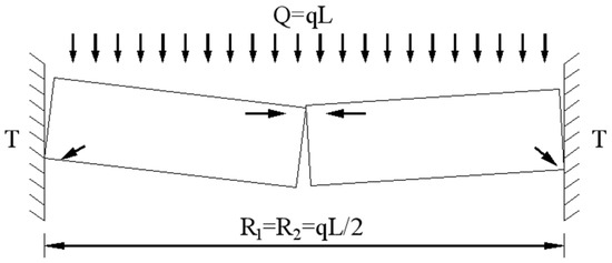
Figure 4.
Mechanical analysis of broken rock.
The conditions for deformation instability of the structure are as follows: During the rotation of rock blocks, local stress concentration occurs at compression points, leading to plastic deformation or even tensile failure at those points. This can exacerbate rock block rotation, ultimately causing structural instability. According to the theory of three-hinge arch equilibrium, the relationship between the load q and the tensile strength σt of the rock beam at the point of fracture is as follows:
The condition for structural deformation instability is that σt is greater than σc. The instability and failure of fractured rock layers are directly proportional to the square of the span-to-thickness ratio, positively correlated with the load, and inversely correlated with the compressive strength of the rock layer. This highlights the span-to-thickness ratio as a critical factor influencing the instability of rock beams.
Therefore, strengthening the roof support strength of ultra-large span open-off cuts and selecting appropriate support parameters become essential tasks in ensuring mine safety and production efficiency.
3. Design of Active Support Parameters for Surrounding Rock with Ultra-Large Span Open-Off Cut in Thick Coal Seam
3.1. Theoretical Analysis of Support Parameter Design
Ultra-large span open-off cuts differ from conventional roadways, as the critical stress-to-span ratio that the cutting area roof can withstand is only one-fourth that of the roadway. At the installation area of the underground chamber within the open-off cuts, the span reaches a maximum of 11.8 m. Numerical simulation results indicate a significant stress concentration at the expanding openings and the central roof area, which poses considerable challenges for the support of these galleries. To design and optimize the support parameters for these ultra-large span open-off cuts, Proctor’s theory and the natural equilibrium arch theory were employed to calculate the unstable rock layer thickness suspended in the open-off cuts [15].
The expression for the natural equilibrium arch height b can be represented as follows:
where a is half of the open-off cut span, taken as 4.9 m; f is the direct roof Proctor’s coefficient, with a value of 3 for coarse sandstone; h is the gallery height, set at 3.8 m; θ is the friction angle, with a value of 25° for the coal layer where the open-off cuts are located; f is the Proctor’s coefficient for coal, set at 1.13.
The formula for calculating the length of the rock bolts is given by:
where l1 is the exposed length of the rock bolt and is taken as 0.1 m; l2 is the effective length of the rock bolt, ranging from 1.0 to 1.2 m; l3 is the length of the rock bolt deeply embedded into the basic roof, taken as 0.3–0.4 m based on field experience.
The formula for calculating the rock bolt diameter is:
where d is the diameter of the rock bolt in meters; Q is the anchoring force of the rock bolt, obtained from on-site tests, measured at 150 MPa; σt is the tensile strength of the rock bolt, which is a high-strength left-handed threaded steel bolt without longitudinal ribs.
The designed length of the anchor cable should satisfy the following equation:
where L represents the design length of the anchor cable. La denotes the anchoring length of the anchor cable into the relatively stable rock layer.
where K is the safety factor, commonly set at 2 based on empirical data; d1 is the diameter of the cable; fa is the tensile strength of the cable itself; fc is the anchoring strength, set at 400 MPa; Lb is the thickness of the unstable rock layer to be suspended, equivalent to the height of the natural equilibrium arch [18]; Lc is the thickness of the tray and anchors; Ld is the exposed lifting length.
By combining Equations (4) to (8), the calculations for the length of the bolts, bolt diameter, cable length, and the spacing between bolts were obtained, as shown in Table 1.

Table 1.
Rock bolt, cable calculations, and design values.
Based on the calculated support parameters and in conjunction with commonly used materials in mines, rational design values for the support parameters were derived. The designed support cross-sections are illustrated in Figure 5 (roadway surrounding rock support diagram). The initial design for the support of the open-off cuts in the 81309 working face, design Scheme 1 is as follows:
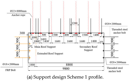
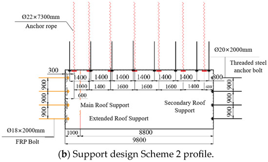
Figure 5.
Roadway surrounding rock support diagram.
Roof: Ø20 mm × 2000 mm high-strength left-handed threaded steel bolts, spaced at 1000 mm, 1400 mm, and 1500 mm, with intervals of 900 mm; Ø22 mm × 8000 mm anchor cables, spaced at 1400 mm × 900 mm and 1600 mm × 900 mm.
Rib: Ø20 mm × 2000 mm high-strength left-handed threaded steel bolts; Ø18 mm × 2000 mm fiberglass reinforced plastic (FRP) bolts used for cut-off ribs, spaced at 900 mm × 900 mm. Two additional rock bolts were added at the expanding openings of the open-off cuts to enhance the support strength.
The support parameters for the cutting areas in the 81309 working face were obtained using the analogy method. The support scheme was applied by comparing the lengths and spacing of the rock bolts and cables from the 81308 working face. The support parameters for the open-off cuts in the 81309 working face, design Scheme 2, are as follows:
Roof: Ø20 mm × 2000 mm high-strength left-handed threaded steel bolts, spaced at 1400 mm × 1000 mm; Ø22 mm × 7300 mm anchor cables, spaced at 1400 mm × 1000 mm and 1600 mm × 1000 mm.
Rib: Ø20 mm × 2000 mm high-strength left-handed threaded steel bolts; Ø18 mm × 2000 mm fiberglass reinforced plastic (FRP) bolts used for cut-off ribs, spaced at 900 mm × 1000 mm. The rib bolts are installed horizontally, and on one side of the cut-off rib, fiberglass-reinforced plastic (FRP) bolts are used.
3.2. Numerical Model Establishment
Based on the geological data background of the Baode Coal Mine and the mechanical parameters of the roof and floor of the 81309 working face, a geological model was established using the FLAC3D 5.00 numerical simulation software, with numerical dimensions of 100 m × 100 m × 80 m. Displacement was constrained in the X, Y, and Z-zero directions of the model, and a uniform load of 15 MPa was applied to the top surface, with gravity acceleration set at 10 m/s2. The Mohr–Coulomb constitutive model was adopted, and the model’s bottom and sides were fixed. Different excavation steps were set up to conduct separate simulations for design Scheme 1 and design Scheme 2. The aim was to investigate the stress, deformation, and failure characteristics of thick coal seam surrounding rock with an exceptionally large span under different support conditions and to perform a comparative analysis of the overall control effectiveness of the surrounding rock. The mechanical parameters of the surrounding rock are shown in Table 2, and the numerical simulation model is depicted in Figure 6.
Table 2.
Rock mechanical parameters.
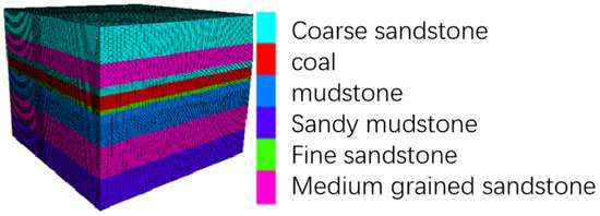
Figure 6.
Numerical model diagram.
3.3. Numerical Analysis of Support Parameter Design
Monitoring of displacements, stress states, and plastic deformation zones at 30 m and 60 m positions in the roadway for coal mining revealed the following simulated results:
- (1)
- Displacement field analysis of surrounding rock
As shown in Figure 7, numerical simulation results indicate that compared to support design Scheme 2, both the bottom heave in the floor and floor heave in Scheme 1 remain within 40 mm. However, the peak subsidence of the roof in Scheme 2 reaches 81.3 mm, while in Scheme 1, the peak subsidence of the roof is 67.9 mm. Under the conditions of Scheme 1, compared to Scheme 2, the sidewall displacements are reduced by 16.6%, and the roof subsidence is reduced by 16.3%. Therefore, Scheme 1 exhibits superior support effectiveness in controlling the roof layer displacement in the roadway compared to Scheme 2.
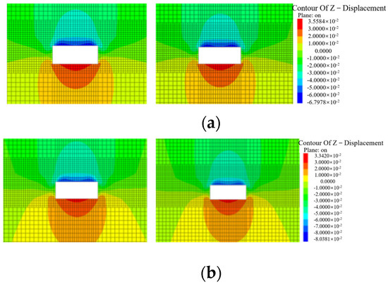
Figure 7.
Displacement field of surrounding rock: (a) rock displacement in the surrounding area at 30 m and 60 m for Scheme 1; (b) rock displacement in the surrounding area at 30 m and 60 m for Scheme 2.
- (2)
- Stress field analysis of surrounding rock
When comparing the stress fields of surrounding rock for the two support design schemes, it is observed that under Scheme 1, the load-bearing capacity of the surrounding rock is increased, resulting in a reduction in peak compressive stress by 3 MPa compared to Scheme 2. The stress concentration areas on both sidewalls are reduced for both schemes. Both schemes exhibit a bimodal stress relief area on the roof, with peak tensile stress concentrated in the middle of the roof. In Scheme 1, the peak tensile stress is reduced by 1 MPa compared to Scheme 2. The stress relief range in the sidewall is reduced by 5% in Scheme 1 compared to Scheme 2, and the high-stress concentration range is reduced by 21%. Therefore, Scheme 1 exhibits a significant effect in controlling the degree of stress concentration in the surrounding rock of the roadway compared to Scheme 2.
- (3)
- Plastic zone analysis of surrounding rock
Through numerical simulation calculations, the distribution of plastic zones in the surrounding rock of the roadway is obtained for both support design schemes, as shown in Figure 8.
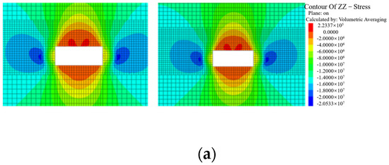

Figure 8.
Surrounding rock stress field: (a) vertical stress at 30 m and 60 m for Scheme 1. (b) Vertical stress at 30 m and 60 m for Scheme 2.
From Figure 9, it is evident that under support design Scheme 1, the distribution range of the plastic zone in the surrounding rock is significantly reduced compared to Scheme 2. In Scheme 2, there is a tension–shear failure zone near the roadway, whereas in Scheme 1, shear failure is observed around the tunnel, with no tension–shear failure. The depth of floor failure in Scheme 2 is greater than that in Scheme 1, with a relatively larger range of deformation failure. Numerical simulation demonstrates that under Scheme 1, the support enhances the stability of the roadway, significantly reducing plastic failure in the top corners of the tunnel and resulting in a 26% decrease in the plastic failure area.
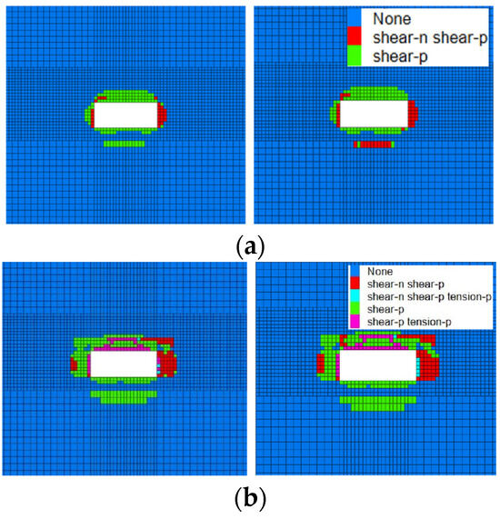
Figure 9.
Plastic zone of surrounding rock: (a) plastic failure at 30 m and 60 m for Scheme 1; (b) plastic failure at 30 m and 60 m for Scheme 2.
Through a numerical simulation and analysis using FLAC3D, a comparison of displacement variations, stress states, and plastic failure zones of the surrounding rock in the roadway was conducted. It is evident that the support effectiveness of Support Scheme 1 surpasses that of Scheme 2 obtained through analogous methods. Scheme 1 effectively maintains the stability of the surrounding rock in ultra-large span roadway excavation, achieving the required support effect. Therefore, Scheme 1 should be applied for the roadway support in the 81309 working face during excavation in the coal mining industry.
4. Field Application
4.1. Test Site
In order to assess the effectiveness of the support design scheme for large-span cutting in thick coal seams, displacement monitoring of the surrounding rocks in the excavated area was conducted. Within the cutting area of 81309 working face, three sets of roadway surrounding rock displacement monitoring stations were installed. The first station was positioned 30 m from the end of the cutting, and subsequent stations were placed at 30 m intervals, named 1# measuring point, 2# measuring point, and 3# measuring point. Deep-seated displacement monitoring devices were buried to measure the deformation of the surrounding rocks, aiming to validate the rationality of the support optimization scheme. The specific layout of monitoring stations is illustrated in Figure 10.
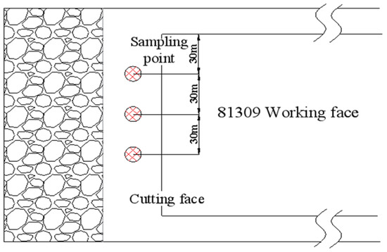
Figure 10.
Layout diagram of roadway surface displacement measuring station.
4.2. Monitoring of Cutting Surrounding Rock Deformation
Accurate measurement of the displacement of the cutting surrounding rocks was performed, and irrelevant data from abandoned monitoring points were excluded. The relationship between the number of monitoring days and displacement is illustrated in Figure 11.
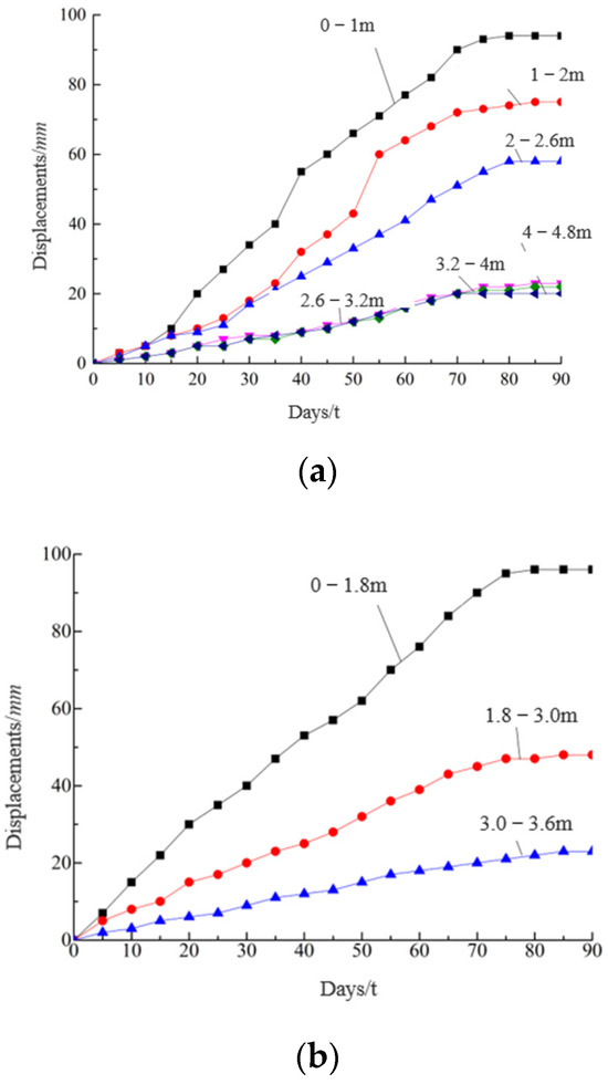
Figure 11.
Approach amount of roadway roof and two sides in 81309 working face cutting: (a) approach amount of both sides of the roadway in the 81309 working face cutting: (b) changes in the roof and floor of the 81309 working face cutting.
From the observation data in Figure 10, it is observed that with the passage of time, the displacement of the roadway roof, floor, and sides generally increased within the first 60 days and then gradually stabilized.
Both the roof and the sides of the roadway exhibited maximum displacement at shallow depths. The maximum approach amount of the roof reached 96 mm. A comprehensive analysis of the monitoring results indicated that the displacement of the roadway sides and the roof was less than 100 mm, and the displacement at a depth of more than 2 m from the cutting surface was less than 60 mm. These values met the requirements of the design regulations. The on-site experimental results were consistent with the results obtained from numerical simulations.
5. Conclusions
- (1)
- In order to effectively control the stability of the surrounding rock of the large-span cutting roadway, combined with the geological conditions of Baode Coal Mine, the optimal supporting scheme parameters are proposed by using theoretical analysis, numerical simulation, and field tests.
- (2)
- The ultra-large span of the open-off cutting in thick coal seams is the primary factor affecting the stability of the cutting. The span is inversely proportional to the stress borne by the cutting roof. The ratio of span to thickness is a key factor influencing the stability of the roof layer and the stability of rock beams.
- (3)
- Through comprehensive comparative analysis of changes in surrounding rock stress, displacement, and plastic zone through numerical simulation, Scheme 1 proved significantly superior to Scheme 2. Under Scheme 1, the approach amount of the roof, floor, and sides decreased by approximately 16%, and the extent of plastic zone damage reduced by 26%.
- (4)
- Under Scheme 1, roadway surrounding rock displacement monitoring was conducted after the cutting excavation. The monitoring data showed that the maximum deformation of the surrounding rocks was less than 100 mm, complying with the design regulations. This indicates that the support parameters of this scheme effectively maintain the stability of the cutting area.
Author Contributions
Methodology, investigation, and writing—original draft, L.P.; formal analysis, conceptualization, and writing—review and editing, Y.L. and Z.S.; writing—review and editing, Y.C. and X.Z. All authors have read and agreed to the published version of the manuscript.
Funding
This study was supported by the Science and Technology Innovation and Entrepreneurship project of TDTEC (No. 2022-QN001, No. 2022-2-MS003).
Institutional Review Board Statement
Not applicable.
Informed Consent Statement
Not applicable.
Data Availability Statement
The data presented in this study are available on request from the corresponding author. The data are not publicly available due to the containing information that could compromise the privacy of research participants.
Conflicts of Interest
The authors declare that this study received funding from the Science and Technology Innovation and Entrepreneurship project of TDTEC. The funder was not involved in the study design, collection, analysis, interpretation of data, the writing of this article or the decision to submit it for publication.
References
- Wang, X.; Tang, J.; Li, Y. The Failure Law and Combined Support Technology of Roadways with Weak Surrounding Rock in Deep Wells. Appl. Sci. 2023, 13, 9738. [Google Scholar] [CrossRef]
- Gu, S.; Wang, X.; Huang, R.; He, H. Analysis of High-Stress Roadway Floor Deformation Mechanism and Control Technology. J. Saf. Sci. Technol. 2020, 16, 57–63. [Google Scholar]
- Chai, Z.; Kang, T.; Li, Y. The Role of Large Section Cutting Hole Anchorage Support in Extra Thick Coal Seam. J. China Coal Soc. 2008, 7, 732–737. [Google Scholar]
- Jia, H.; Ma, N.; Zhao, X. Collapse Law of Large-Span Cutting Roof in Deep Buried Thin Bedrock. J. Min. Saf. Eng. 2014, 5, 702–708. [Google Scholar]
- Li, C.; Cao, Y.; Cheng, Z. Research on Roof Collapse and Bending Law of Large-Span Roadway and Support Technology. J. Min. Saf. Eng. 2015, 6, 978–983+988. [Google Scholar]
- He, F.; Xu, L.; Wu, H.; Wang, Y. Evolution of Fracture Field in Thick Coal Roof Large Section Cutting Hole and Surrounding Rock Stability Analysis. J. China Coal Soc. 2014, 2, 336–346. [Google Scholar]
- Chi, G.; Zhang, L.; Tang, H. Comprehensive Control Technology for Extra Large Section Cutting Hole Surrounding Rock. Coal Sci. Technol. 2017, 11, 27–31. [Google Scholar]
- Ping, Z.; Ma, N.; Wei, J. Combined Support Technology of Large Section Roadway in High-stress Fractured Surrounding Rock. Procedia Eng. 2011, 26, 1270–1278. [Google Scholar] [CrossRef][Green Version]
- Wang, H. Active and Passive Combined Support Technology for Large Span Cutting Hole in Thick Coal Seam. Coal Sci. Technol. 2018, 46, 33–38. [Google Scholar]
- He, F.; Bo, Y.; Xu, Z. Study on Surrounding Rock Stability and Reasonable Anchor Configuration of Thick Coal Seam Cutting Hole. J. Min. Saf. Eng. 2015, 2, 233–239. [Google Scholar]
- Xu, Z.; Li, C.; Cao, Y. Study on the High Strength Cable Truss System Control of the Surrounding Coal Roadway Excavated in Regions Left Intensively Mining-Induced Stresses. Appl. Sci. 2023, 13, 10504. [Google Scholar] [CrossRef]
- Chai, J.; Han, Z.; Qiao, Y. Stability Research of Top Coal in Large Span Cutting Hole under Stratified Mining of Goaf. J. Min. Saf. Eng. 2022, 2, 282–291. [Google Scholar]
- Xie, Z.; Zhang, N.; Qian, D. Rapid Excavation and Stability Control of Deep Roadways for an Underground Coal Mine with High Production in Inner Mongolia. Sustainability 2018, 10, 1160. [Google Scholar] [CrossRef]
- Xie, Z.; Li, Y.; Zhang, N. Model experiment research on HPTL anchoring technology for coal-rock composite roof in deep roadway. Sci. Rep. 2023, 13, 2381. [Google Scholar] [CrossRef] [PubMed]
- Liu, J.; Zhang, L.; Xie, L. Comprehensive Control Technology Research of Extra Large Section Cutting Hole under Complex Technical Conditions. Coal Sci. Technol. 2021, 49, 55–59. [Google Scholar]
- Hu, Y.; Liu, Y.; Shi, L. Research on Supporting Technology for Surrounding Rock of Inclined Large-Span Open-Off Cut Roadway. Geotech. Geol. Eng. 2020, 38, 1873–1884. [Google Scholar] [CrossRef]
- Zhou, B.; Yuan, L.; Xue, S. Analysis of Weakening the Bearing Capacity of Roof Strata in Coal Roadways. J. Saf. Sci. Technol. 2018, 9, 122–128. [Google Scholar]
- Luo, X.; Gao, X.; Wang, W. Optimization and Application of Bolt and Cable Support Parameters in Roadway Based on Natural Balance Arch. Coal Technol. 2022, 41, 56–59. [Google Scholar]


Disclaimer/Publisher’s Note: The statements, opinions and data contained in all publications are solely those of the individual author(s) and contributor(s) and not of MDPI and/or the editor(s). MDPI and/or the editor(s) disclaim responsibility for any injury to people or property resulting from any ideas, methods, instructions or products referred to in the content. |
© 2023 by the authors. Licensee MDPI, Basel, Switzerland. This article is an open access article distributed under the terms and conditions of the Creative Commons Attribution (CC BY) license (https://creativecommons.org/licenses/by/4.0/).