Review

Effect of 3D Printing Parameters on the Fatigue Properties of Parts Manufactured by Fused Filament Fabrication: A Review

School of Engineering, Edith Cowan University, Joondalup, WA 6027, Australia
*
Authors to whom correspondence should be addressed.
Appl. Sci. 2023, 13(2), 904; https://doi.org/10.3390/app13020904
Submission received: 22 November 2022 / Revised: 28 December 2022 / Accepted: 6 January 2023 / Published: 9 January 2023
(This article belongs to the Section Additive Manufacturing Technologies)

Abstract

:
The advancement in 3D printing techniques has raised the hope to use additively manufactured parts as final products in various industries. However, due to the layer-by-layer nature of AM parts, they are highly susceptible to failure when they are subjected to fatigue loading. This review provides a detailed account of the influence of 3D printing parameters on the fatigue properties of parts manufactured by fused filament fabrication (FFF). Existing standards for fatigue testing of polymers and their limitation for 3D-printed parts are discussed. In addition, the cyclic behaviour of polymers is reviewed, and the impact of 3D printing parameters on the mechanical behaviour of FFF parts under tensile, compressive, flexural, and bending fatigue is investigated according to the published results in the literature. Finally, a summary of the works undertaken and suggestions for future research are provided. The influence of 3D printing parameters on the fatigue performance of prints can be different from that seen in the case of static loading and strongly depends on the fatigue loading type. While cross-over infill patterns, higher infill density, and higher layer height favour achieving higher fatigue strength in all loading types, raster orientation is best to be aligned parallel to the tensile loads and perpendicular to the compressive, flexural, and bending forces. In the case of tensile and flexural loading, Y build orientation yields the best result. Finally, print velocity was found to be less significant compared to other parameters, implying that it can be set at high values for faster printing.

1. Introduction

In recent years, additive manufacturing (AM) or 3D printing has got the highest interest from industries, including aerospace [1], automotive [2], biomedical [3], construction [4], food [5], and other industries [6]. AM offers the freedom of design, implying that complex geometries can be manufactured in one step, eliminating the tooling cost and post-processing steps, such as machining [7]. Further, several components can be manufactured in one step via AM, reducing the weight of the final product and therefore saving up to 33% fuel in transport industries [8]. The economic benefits of AM on supply chains include lower material waste, simplified production processes, and improved flexibility because the finished product can be manufactured near the customer.
Among the various AM techniques, fused filament fabrication (FFF), also referred to as fused deposition modelling (FDM) or material extrusion (MEX), is considered one of the most widely used and cost-effective manufacturing methods for plastic parts. In FFF, 3D parts are created using a continuous thermoplastic or composite material thread in filament form. Figure 1 schematically illustrates the 3D printing of a typical tensile specimen. This method includes an extruder that feeds the plastic filament through an extruding nozzle, which is selectively deposited layer by layer onto the build platform after melting in a predetermined automated path. Depending on the specimen orientation, supporting structures are 3D-printed through a different nozzle to support the structure of prints. Supporting structures, as sacrificial materials, are necessary to secure overhanging sections to the previous layers when the crucial inclination angle (often 45°) is reached and to assist in removing the part from the build plate without damaging the main part. These structures also favour maintaining the part’s structural integrity during metal printing by reducing distortions caused by thermal stresses [9]. A review of different support structures and their designs for AM parts is provided in [10]. Supporting filaments are usually extruded thorough a different extruder. The second extruder can also be used to print materials with different colours or mechanical or electrical properties [11,12]. The extruders (nozzles) are attached to the print head that can move in the X and Y directions. However, using two extruders implies high inertia to the print head, decreasing the printing accuracy. Furthermore, while the active extruder is operating, the remaining molten plastic in the inactive extruder might leak into the component [12].
Like other parts, FFF prints (referred to as “print” hereafter in this paper) are susceptible to mechanical failures during their service life. Of known failures, fatigue is structural damage caused by cyclic loading that might result in cracking or rupturing of the part at stresses lower than its yield strength. Therefore, it is vital to understand the resistance of FFF prints to cyclic loading and unloading [13]. Generally, FFF prints possess weaker strength than their injected-moulded (IM) counterparts due to the inherent flaws, such as void spaces, improper adhesion between extruded filaments, and material degradation during printing. Further, thermal stresses between extruded filaments may cause the formation of internal cracks, which can progress during the loading stage [14]. Padzi et al. [15] characterized the mechanical properties of tensile acrylonitrile butadiene styrene (ABS) specimens fabricated via injection moulding and FFF printing. The specimens were subjected to quasi-static and fatigue tensile loads at stresses equal to 40%, 60%, and 80% of their ultimate tensile strength (UTS). The authors concluded that the FFF prints had considerably inferior performance, showing approximately 63% and 41% lower tensile and fatigue strength, respectively, compared to that observed in IM specimens. Figure 2 compares the S–N curves of injection-moulded and FFF-printed ABS specimens at different stress levels. In another study by Puigoriol-Forcada et al. [14], the flexural fatigue life of FFF polycarbonate prints was reported to be notably lower than that of their IM counterparts.
However, the quality and mechanical strength of FFF prints can be substantially enhanced by introducing reinforcing fillers to the polymer matrix (composite filament) or optimizing the 3D printing parameters. In the former method, fillers of different shapes and materials are mixed with the polymeric filament to increase its strength. However, it has been shown that the fatigue strength of FFF prints can be enhanced [16,17] or deteriorated [18] by introducing filler materials, depending on the loading type, material, shape, and content of the added fillers. Therefore, optimizing 3D printing parameters is the key to obtaining the highest potential mechanical strength in FFF parts, including composite prints. Miller et al. [19] fabricated thermoplastic polycarbonate urethane (PCU) samples using injection moulding and FFF printing. They subjected the fabricated samples to monotonic compression and tensile tests, as well as shear and tensile fatigue loads. They concluded that the monotonic and fatigue strength of FFF samples not only matched that of IM parts but also outperformed them in some cases. Choosing suitable printing parameters, such as a high nozzle temperature, was stated as the key to achieving high-quality parts in this work. It was also reported by Arbeiter et al. [20] that high-quality PLA prints with near isotropic fatigue properties are possible by implementing optimum parameters during FFF printing.
These results highlight the significance of 3D printing parameters in obtaining durable prints with high fatigue properties. Although the influence of 3D printing parameters on the quasi-static performance of prints has been widely discussed within the literature [21,22], there are limited accounts of this effect on fatigue performance. Numerous studies are available on the overview of the fatigue data in additively manufactured parts; however, the influence of 3D printing parameters has not been discussed in detail. An overview of fatigue data in additively manufactured parts was provided by Safai et al. [13]. A discussion of FFF technology was included in the paper cited above, but no in-depth analysis of the impact of different 3D printing settings was included. In addition, Shanmugam et al. [23] reviewed the fatigue behaviour of FFF parts from a material standpoint. This study aims to provide a detailed account of the effect of 3D printing parameters on the performance of FFF parts under tensile, compressive, flexural, and rotating bending fatigue. Influential 3D parameters are discussed, and the fatigue testing of polymers is explained. Research gaps are then identified, and suggestions for future works are provided in this review.

2. Three-Dimensional Printing Parameters

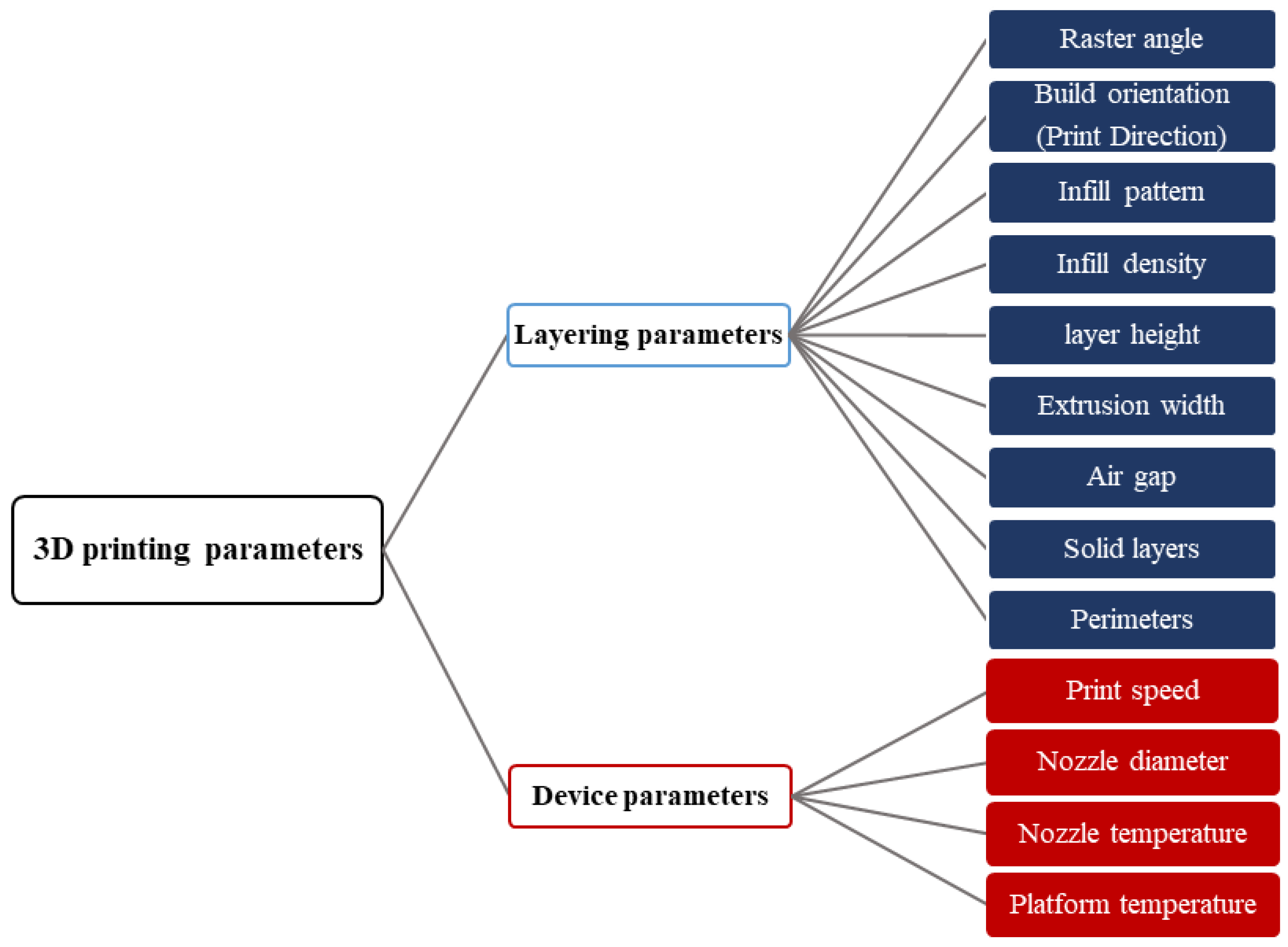
Three-dimensional printing parameters can be categorized into two groups, as shown in Figure 3. The first group includes topological parameters that can be adjusted via the slicing software, referred to as “layering parameters”. The second group, i.e., “device parameters”, are those directly related to the 3D printing device. According to a study conducted by Jap et al. [24], the main parameters affecting the fatigue strength of FFF prints include build orientation, infill density, number of shells, raster angle, nozzle temperature, platform temperature, printing speed, layer height, and nozzle diameter.
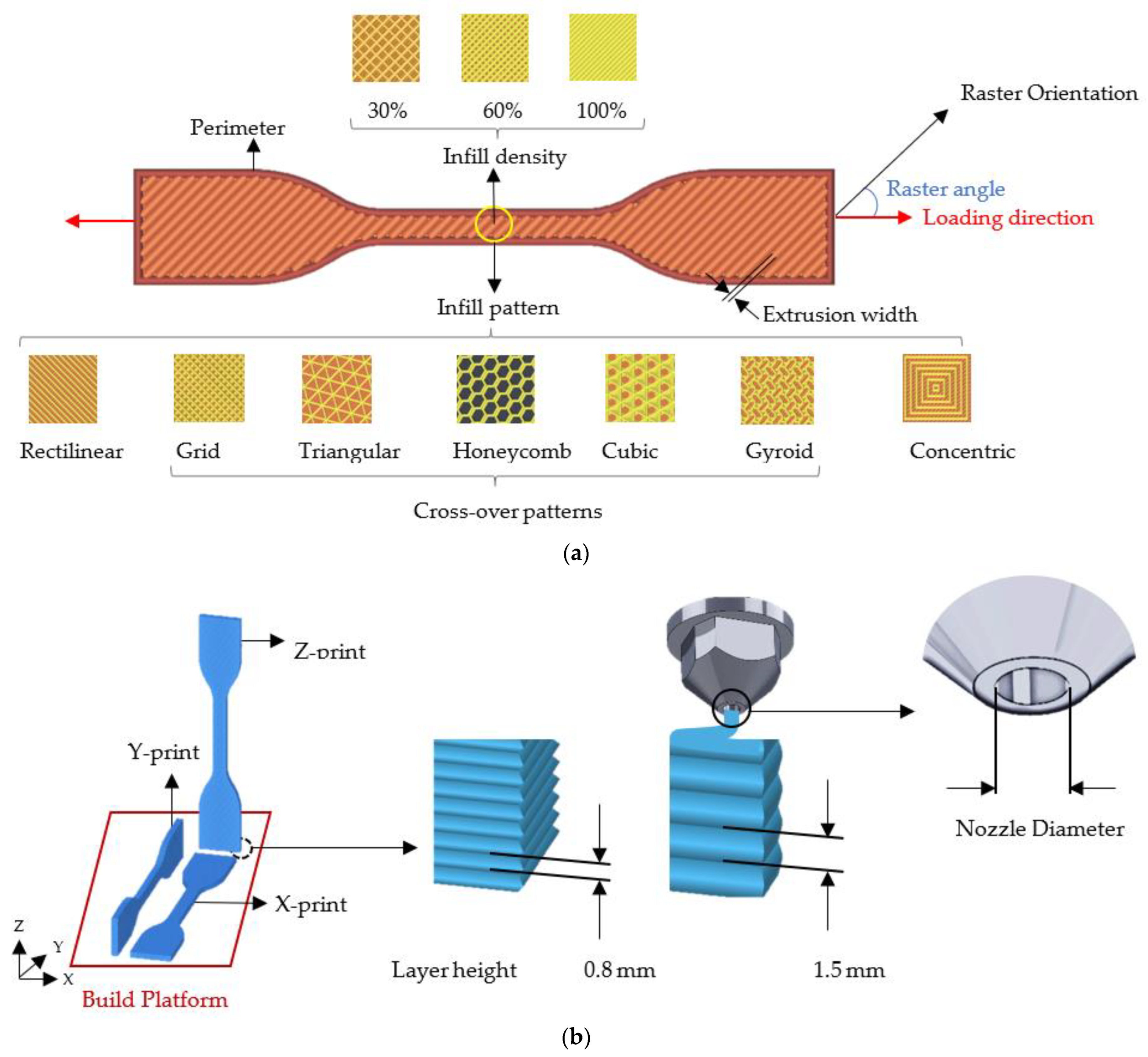
Layering and device parameters are shown in Figure 4. Figure 4a illustrates the extrusion width, infill pattern, infill density, and perimeter (shell). The extrusion width is the width of the extruded filament. This parameter is adjusted by the nozzle pressure and normally can be from 90% to 250% of the nozzle diameter. Extruded filaments in each layer are laid in a configuration called “infill pattern”, determining the internal structure of the print. In this regard, different infill patterns, including rectilinear, grid, and honeycomb, can be used, as indicated by Figure 4a. In this study, patterns such as grid and honeycombs are referred to as “cross-over” patterns since the extruded filaments of each layer or successive layers cross each other with an angle larger than zero. The fraction of the solid volume within the printed object is termed “infill density”, which is a determining factor for the mechanical properties of the print. The infill density can range from 0% to 100%, with 0% being an empty volume and 100% showing a fully solid object. In addition, to maintain the structural integrity of the 3D-printed object, perimeter/shell layers are used to enclose the internal structure. Perimeters are fully dense layers that can have a different width from the as-extruded filaments inside the part. Some solid layers (with 100% infill density) may be positioned at the bottom or top of the object to strengthen it and avoid the pillowing effect. Pillowing occurs at the top layer of prints, appearing as irregular bumps and undesired holes. Pillowing is caused by improper cooling of the top layers and can be avoided by using solid layers at the top [25].
Other parameters include the build orientation, layer height, and nozzle diameter, as illustrated in Figure 4b. The build orientation determines the positioning of the object of interest in the 3D printer chamber. In other words, the build orientation denotes the direction of the specimen with respect to the build platform. Figure 4b shows the build platform and tensile specimens fabricated at three orthogonal build orientations, i.e., X, Y, and Z, denoting the perpendicularity of the build platform to the sample’s thickness (shortest length), width (medium length), and height (highest length), respectively. This definition applies to all samples discussed in this study. Finally, the height of each layer can be adjusted in the slicing software. As depicted in Figure 4b, the smaller the layer thickness, the larger the number of required layers.
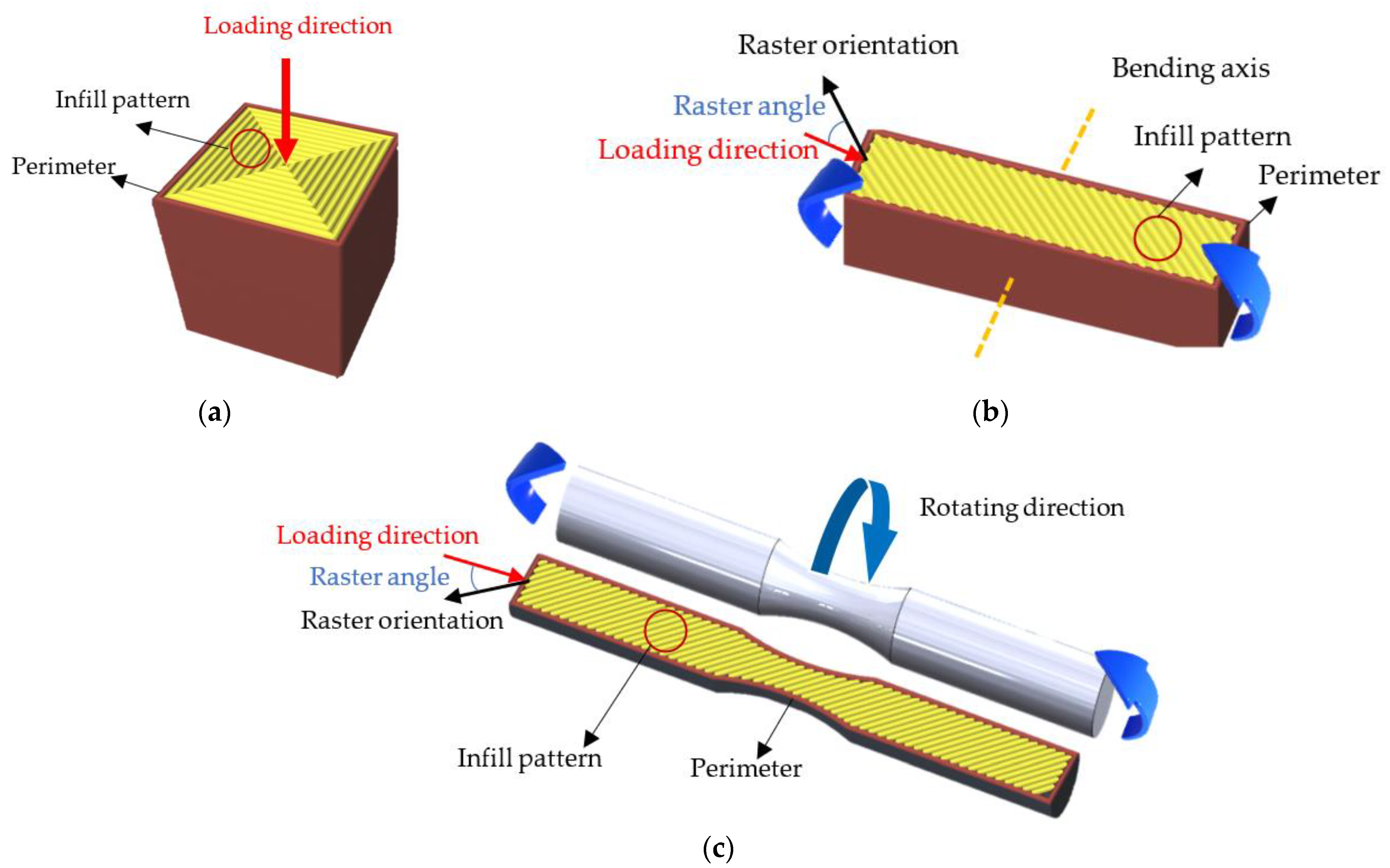
Raster orientation denotes the direction of extruded filaments in the build platform. This study defines the raster angle as the angle between the raster orientation and the stress direction when they are at the same plane. This definition has been derived according to various works studied in this review. Although some studies define the raster angle as the angle of the raster orientation with respect to the x-axis of the build table [26], the impact of the raster angle on the mechanical performance of prints may be neglected if the loading direction is not taken into account. The stress direction is the same as the loading direction in pure tension/compression states. Figure 4a illustrates the raster angle in tensile specimens. Since the stress direction and deposited filaments are not in the same plane in pure compression, the raster angle is not defined for compressive specimens, as shown in Figure 5b. In flexural and rotating bending specimens, the stress direction is perpendicular to the bending axis, as depicted in Figure 5b. The raster angle in flexural and rotating bending fatigue specimens is depicted in Figure 5b and 5c, respectively.

3. Fatigue in Polymers and FFF Prints

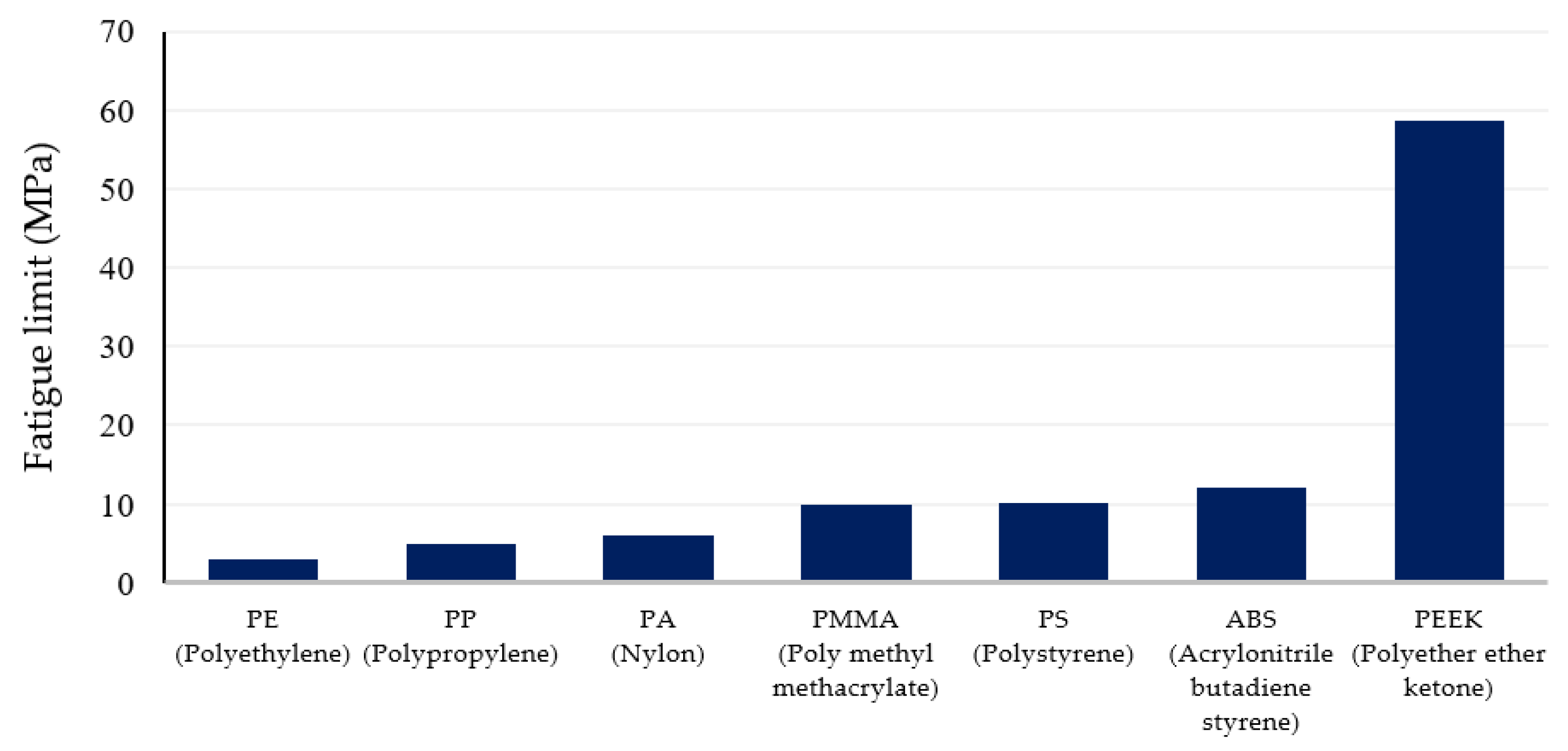
Fatigue in polymers occurs both as thermal and as mechanical failure. Thermal failure occurs due to hysteretic heating and consequent thermal softening of polymers, leading to ductile fractures [27]. In polymers, the dissipated energy (plastic work energy) is converted to heat within the material, resulting in the gradual thermal degradation of polymeric chains [28]. When subjected to fatigue loading, the induced plastic deformation in each mechanical cycle is converted to thermal energy, which cannot be transferred to the surrounding environment due to the low thermal conductivity of polymers. Thus, the generated heat is stored within the material, leading to overheating and stiffness loss. Consequently, stiffness loss leads to an increase in specimen deformation and failure. If the generated heat reaches the glass transition temperature of the polymer, mechanical properties degrade quickly. Therefore, using materials with a higher glass transition temperature in load-bearing applications is beneficial. For instance, poly(para-phenylene) possesses high fatigue properties due to its relatively high glass transition temperature (~177 °C) [29]. Polyacrylamide, oolyurethane, and PTFE are among the polymeric materials with a high glass transition temperature [30]. Figure 6 illustrates the fatigue limit of some common filament materials. Adding ceramic or metal fillers can be a solution to increase the fatigue strength when thermal failure is dominant. This is because filler materials contribute to fatigue strength enhancement through the energy dissipation mechanism in which a part of the induced energy is absorbed by the filler materials and is dissipated as the deformation of the reinforcement phase. Thus, less energy is converted to heat within the polymeric matrix [31].
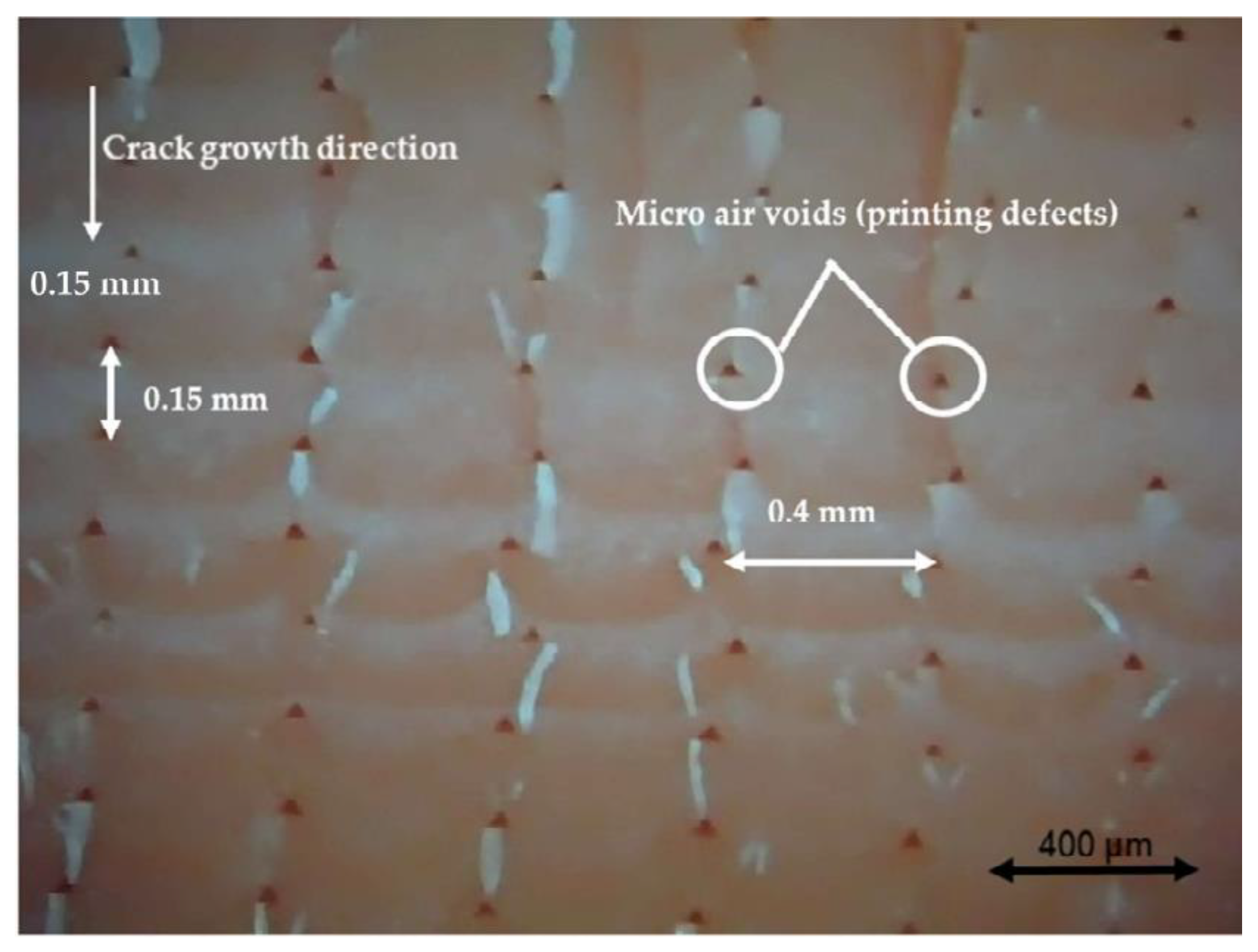
Another failure mode in polymers is the mechanical failure that occurs under fatigue stresses and is greatly affected by stress concentration. Generally, fatigue failure occurs in high-stress-concentration areas. In FFF prints, internal holes (printing defects) serve as stress concentration zones, where the fatigue failure typically starts. These holes are formed due to the round shape of extruded filaments. Figure 7 illustrates the internal holes in a cross-sectional view of an ABS print subjected to fatigue loading. The bright-white lines in this figure show microcracks initiated from internal holes and extended along the loading direction.
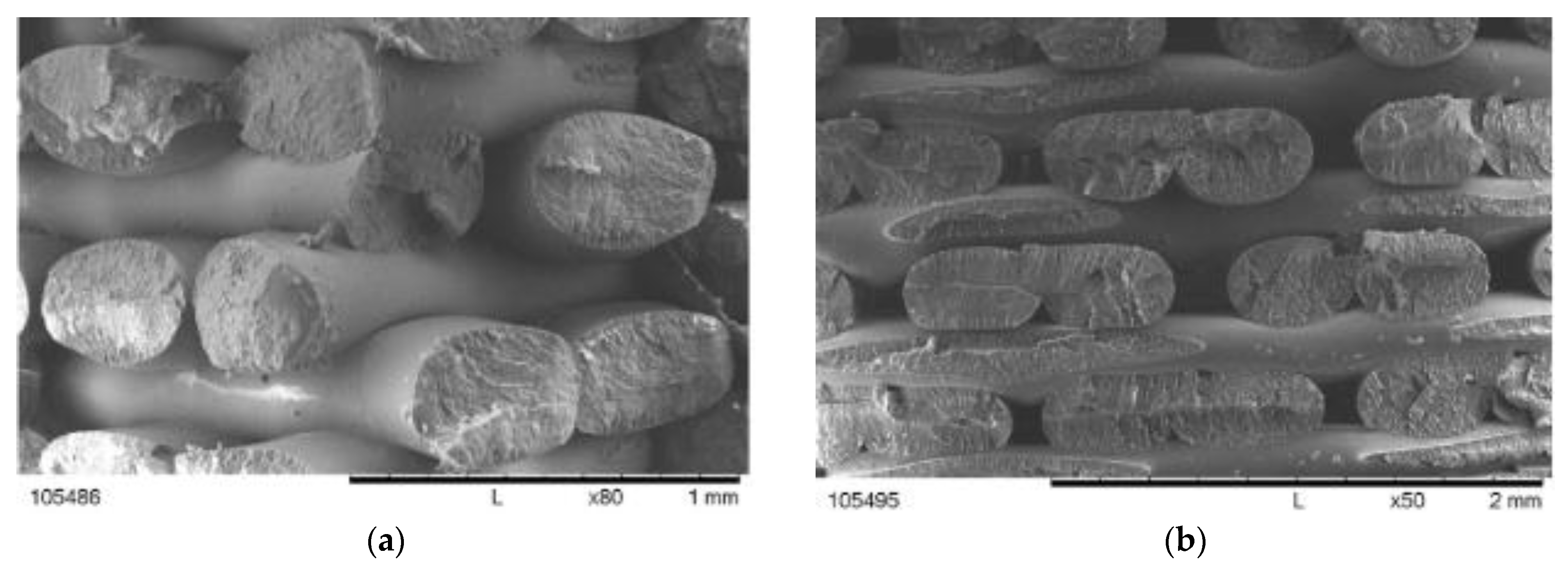
In a homogenous tensile specimen, fatigue failure occurs in the middle section (necking area) where the stress is highest. However, in FFF prints, failure can appear at different areas. In many cases, failure occurs around the shoulders. According to classical lamination theory, this can be attributed to the change in cross section and fibre diversion, which causes the local stresses to be focused near the shoulder area [36]. Figure 8 illustrates the initiation and propagation of tensile fatigue cracks around the shoulder area in an Ultem 9085 print [36].
Since 3D printing parameters affect the quantity and shape of internal holes [35], they also influence the fatigue performance of fabricated specimens. For instance, Figure 9a–c shows the tensile fatigue failure of PLA specimens fabricated at raster angles of 0°, 90°, and 45°, respectively [37]. As can be seen in Figure 9a, the failure point of all 0° prints is located between the neck and shoulder. However, in the 90° and 45° prints, failure has appeared at different locations, suggesting that the stress concentration area might change depending on the raster angle.
Jap et al. [24] found a distinct fatigue failure in ABS prints fabricated with 0°/90° and 45°/45° grid patterns. As shown in Figure 10a, in a −45°/45° print, internal holes are angled to the tensile force (normal to the screen). For 0°/90° specimens, however, the holes are perpendicular to the loading direction. Thus, as proven by the tests, −45°/45° specimens perform better under cyclic loading due to having more material (less void volume) normal to the tensile stress [24].
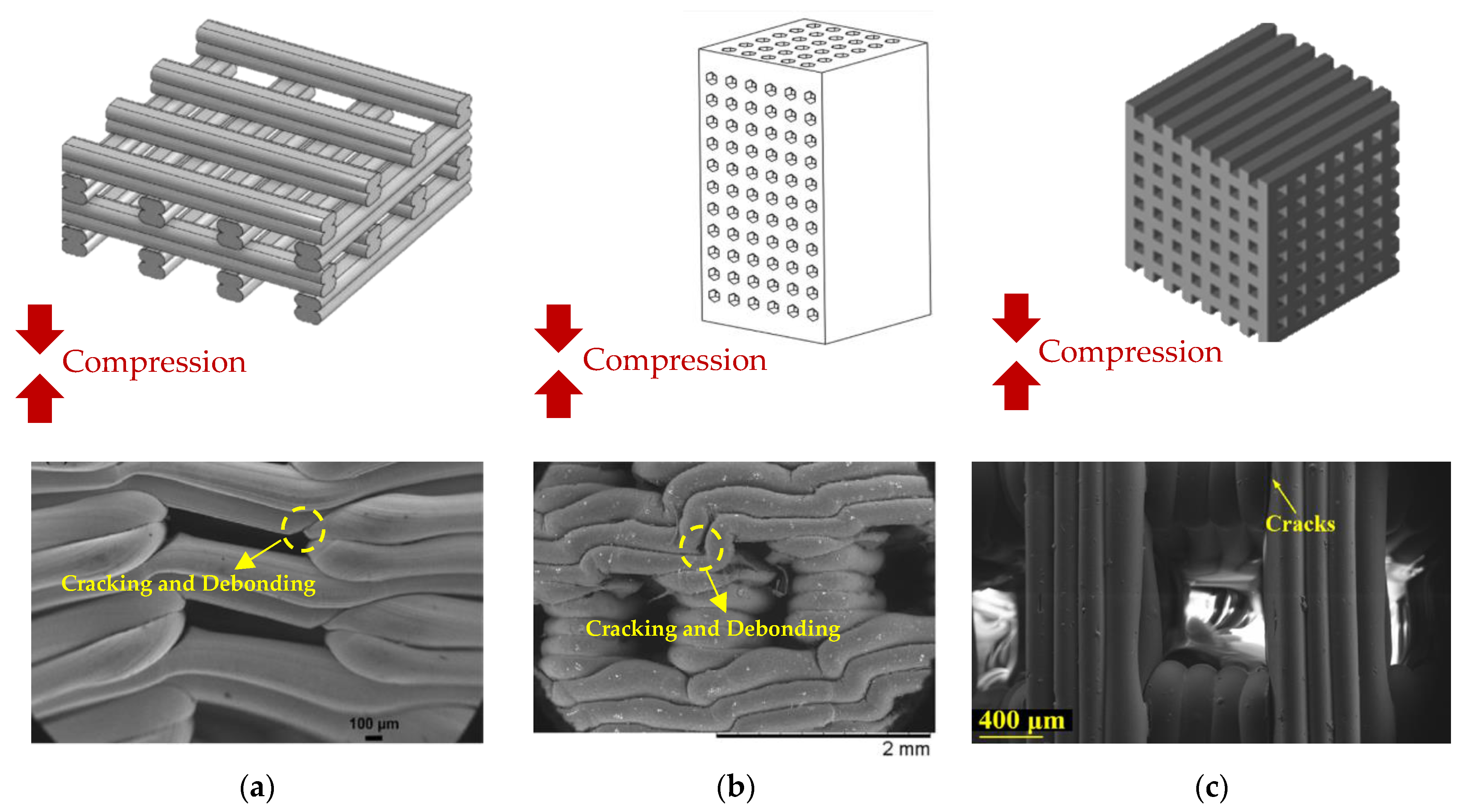
Similar to tensile specimens, stress concentration is the primary reason for mechanical failure of FFF prints under compressive fatigue. According to Senatov et al. [17], mechanical failure in FFF prints occurs due to the slippage of layer interfaces at stress concentration zones. Figure 11 shows some PLA prints subjected to cyclic compression at different loading conditions [17,38,39]. The slippage and debonding of adjacent layers are shown in Figure 11a,b. As can be seen, the cyclic compression caused the shear deformation and debonding of adjacent layers in the prints, implying that the layers’ interfaces act as slipping planes and stress concentration areas. Figure 11c also shows that cracks initiated from the layers’ interfaces, highlighting the importance of adhesion strength between extruded filaments.

Fatigue Testing of Polymers

Different standards are used for the fatigue testing of polymers, including ASTM D7774 [40], ASTM D3479 [41], ASTM D7791 and ISO 13003 [42,43], ASTM D6115 and ISO 15850 [44,45], ASTM E739 [46], ASTM E606 [47], and ASTM D4482 [48]. ASTM D3479 investigates the tension fatigue of polymer matrix composites for particular loading and environmental conditions. ASTM D7791 and ISO 13003 are for uniaxial fatigue in plastics, whereas ASTM D7774 is used for three-/four-point bending tests, and ISO 13003 is for all testing methods. ASTM D6115 and ISO 15850 are applicable for crack propagation, i.e., fatigue delamination in the interlaminar region of fibre composites. ASTM E739 can be used for the statistical analyses of fatigue data. ASTM D4482 examines the tensile fatigue resistance of rubber compounds. Finally, ASTM E606 [47] is used for the tensile fatigue testing of plastics under strain-controlled loading. Table 1 summarizes the existing standards for the fatigue testing of polymers.
Although 3D-printed plastics can be tested using the mentioned standards, it is not clear whether they meet the requirements and assumptions of these standards. During 3D printing, layer deposition results in anisotropic properties and partly creates residual stress, making fatigue testing more challenging. Besides, the staircase configuration of FFF prints, internal pores, and extruded filaments’ junctions cause stress concentration at numerous locations, resulting in invalid test results in some cases. For example, ASTM E606 is only used for homogenous materials, while FFF prints are intrinsically heterogeneous. Further, in notched fatigue specimens (e.g., in ASTM D671 [49]), cracks are expected to initiate around the notched zone, while this might not occur in FFF prints due to the presence of numerous stress concentration zones [50]. In addition, ASTM D4482 states that the tested material lacks any initial flaws or cracks, which is not a valid assumption in FFF prints where void gaps exist within the structure.
Given that FFF prints are inherently different from conventionally manufactured plastics, specialized standards for testing FFF prints are to be developed. However, ASTM D7791 and ASTM D7774 are the most used standards for the uniaxial and flexural fatigue testing of FFF prints. In ASTM D7791, a tensile/compression specimen is subjected to uniaxial fatigue loading at the recommended loading frequency of 5 Hz. The endurance limit of the specimen is then recorded when the specimen fails or reaches 1 × 10⁷ cycles. ASTM D7774 regulates the procedures for the three-point/four-point bending fatigue testing of plastics. Similar to ASTM D7791, the loading frequency can be 1–25 Hz; however, to avoid internal heating, 5 Hz is the recommended frequency. It has been demonstrated that increasing the loading frequency causes internal heating in plastics [51], thus affecting the fatigue limit of FFF prints [34,52].

4. Influence of 3D Printing Parameters on the Fatigue Life of FFF Prints

Apart from the material itself, the mechanical strength of FFF prints is greatly affected by the structural stiffness and bonding strength of extruded filaments [53]. The infill density and infill pattern directly affect the print stiffness, while a higher nozzle temperature favours the efficient fusion of filaments, resulting in stronger bonding. The bonding strength is also influenced by the contact area between the extruded filaments, which is impacted by the extrusion width and layer height. However, it should be noted that the effect of 3D printing parameters on different mechanical properties is not the same and varies according to the direction and type of the applied loads. For instance, Ahn et al. [54] showed that the air gap and raster orientation have a remarkable impact on the tensile strength of prints, while compressive strength is not influenced significantly by these factors. Further, the loading type (static or dynamic) should be taken into account when assessing the influence of 3D printing parameters. This is because fatigue strength is greatly influenced by stress concentration, while stiffness is the most determining factor for static loading [29]. Thus, those 3D printing parameters that play a contributing role in the fatigue strength of a print may have a neutral or deteriorating effect on its static strength and vice versa. There are a handful of studies that have investigated this matter in the literature as the concept of fatigue has not been given as much attention as the static strength in FFF prints so far. Table 2 provides a summary of the works carried out on the effect of 3D printing parameters on the fatigue performance of FFF prints. The reviewed works were categorized based on the fatigue type and the tested material. The fixed parameters, variable parameters, testing conditions, standards used for specimen fabrication, and results were tabulated separately, as provided in Table 2. In the following sections, the effect of 3D printing parameters on the fatigue behaviour of FFF prints is reviewed in detail.

4.1. Raster Angle

The raster angle is a determining factor in the tensile and flexural fatigue performance of FFF prints [20,24,37,53,55,57,59,68]. It has been shown that the tensile strength of FFF prints improves by decreasing the raster angle [22]. In an ideal condition where the rasters of each layer are perfectly aligned with the axis of the applied tensile force (raster angle of 0°), the highest tensile strength is achieved [70,71,72]. In the case of flexural and compressive loading, the highest static strength corresponds with grid patterns [54] and perpendicular arrangement [73], respectively.
Despite the static strength, the fatigue strength of FFF prints does not follow a particular trend against the raster orientation for all materials. In PLA prints, the raster angle of 45° has produced the highest tensile and rotating bending fatigue strength, while for ABS prints, 0° has been the optimum raster angle. For PETG prints, the highest fatigue life at high and low tensile stresses is achieved in 0 and 45° raster orientations, respectively. Afrose et al. [37] studied the tensile strength and tensile fatigue behaviour of PLA prints with different raster angles (0°, 45°, and 90°). They observed that 45° prints show the best fatigue performance among the studied specimens. Interestingly, while 0° prints had the highest UTS, they exhibited the lowest fatigue life. The highest tensile fatigue strength was also achieved for 45° PLA prints in the work of Letcher and Waytashek [59]. The endurance limit of 45° prints was reported to be 10 MPa, followed by 5 and 0.5 MPa for 0° and 90° prints, respectively. Arbeiter et al. [20] investigated the tensile fatigue behaviour of notched PLA prints produced with raster orientations of 0° and 90°. They observed no significant difference between the fatigue strength of the printed samples. The authors also concluded that due to implementing a high nozzle temperature (250 °C) and optimum printing parameters, layers were bonded perfectly, resulting in near-homogenous samples. Thus, the raster orientation did not affect the fatigue strength of the samples markedly. As reported in the literature, the optimum raster angle in ABS prints is 0°. By comparing the S–N curves published in [55,57,58], it is evident that 0° prints possess the highest fatigue resistance, followed by 45° and 90° prints in descending order. Similarly, the flexural fatigue life of 0° ABS prints was higher than those of 90° counterparts in the works of Corbett et al. [69] and He et al. [35]. ABS prints produced in the 0° direction resisted around 96,500 fatigue cycles as compared to less than half (~40,700) for 90° prints [35]. In another study, ABS prints at different raster orientations were subjected to cyclic tension for up to 10,000 cycles [53]. Although Y-aligned (0°) prints performed slightly better than 45° and X-aligned (90°) prints, all samples exhibited relatively similar fatigue resistance. Only one study investigated the fatigue behaviour of PETG prints in which tensile PETG specimens were 3D-printed at 0, 45, and 90° raster angles and were subjected to sinusoidal tensile cycles [60]. It was found that 0° prints perform best at high stress amplitudes, followed by grid (45/−45°) and 45° prints. At low stress amplitudes, 45° prints exhibited the highest fatigue life. It should be noted that the fatigue test was not repeated for each data point in the latter study, making it hard to justify the underlying mechanism of this behaviour. However, it can be said that in all cases, 0° and 45° prints have shown higher fatigue performance than other raster angles. In the latter study, transverse (90°) prints had the least performance among other specimens.
The effect of the raster angle on the rotating bending fatigue performance of FFF prints was studied by Azadi et. al. [68]. PLA and ABS were 3D-printed in round shapes as per ISO-1143 in horizontal (0°) and vertical (90°) orientations. All specimens were subjected to sinusoidal bending stress using a Santam rotating bending fatigue device. The fatigue resistance of all prints was reported to be higher at a 0° raster angle compared to that of 90° prints [68].
Although a particular value has not been reported as the optimum raster angle in the studies conducted so far, it can be said 0° and 45° prints perform better than 90° prints in both ABS and PLA prints when subjected to tensile and bending cyclic forces. The significance of the raster angle in compression and combined fatigue loading modes has not been investigated yet. However, it is expected that in compression, the perpendicular alignment of extruded filaments against the loading direction would result in better fatigue performance, as is the case in the static compressive strength of FFF prints. It is noteworthy to mention that the deformation mode plays a decisive role in this regard. In tension, the specimen is stretched; thus, the highest strength is achieved when the extruded filaments are aligned with the applied load. In contrast, parts tend to buckle under compressive force, so an orthogonal arrangement in which the extruded filaments are perpendicular to the applied load gives the highest compressive strength [73].

4.2. Infill Pattern

The pattern in which the filaments are deposited in each layer is called the infill pattern. The infill pattern also determines the inner structure and thus the overall stiffness of the print [74]. In a specified infill pattern, junctions of extruded filaments at each layer (interlayer) or between two successive layers (interlayer) are formed in a certain shape, acting as stress concentration zones [39,62]. These concentration zones make the joint areas susceptible to debonding and cracking [75]. Stress concentration is a primary reason for the fatigue failure of metals and plastics caused by material or geometrical discontinuities. Due to the formation of air gaps and imperfect bonding between layers during the 3D printing process, the fatigue life of FFF prints can be 100 times lower than that of injection-moulded parts [24]. Infill or hole patterns in FFF prints are another source of stress concentration and reduced fatigue life. Therefore, fatigue strength can be affected by the infill pattern by altering the specifications of the joint areas.
A comparison between the results reported in the literature shows that cross-over patterns (e.g., grid and honeycomb) produce samples with higher tensile and bending fatigue resistance compared to those produced with rectilinear/line patterns. For instance, in a study by Ziemian et al. [57], the tensile fatigue resistance of the weakest grid pattern (0/−90) was higher than that of the strongest rectilinear pattern with a raster angle of 0°. In a study conducted on ABS prints, it was observed that the grid pattern (45/−45°) produced the highest tensile fatigue life among the other patterns, i.e., 0°, 45°, and 90° at the same normalized fatigue stress [55]. Similar behaviour has been reported for the rotating bending fatigue of FFF prints. The effect of rectilinear and honeycomb infill patterns on the rotating bending fatigue strength of ABS and PLA–wood composite prints was studied in [64,67] and [18], respectively. Round specimens were fabricated according to ASTM D7774 and were subjected to stress-controlled fatigue cycles. The infill patterns were so printed that the load was aligned with the carrying direction. Figure 12 depicts the used infill patterns and their orientation with respect to the loading direction. The results showed the superiority of the honeycomb pattern in sustaining fatigue cycles.
Among different grid patterns, some literature studies have suggested that 45/−45° grid patterns perform better than other configurations under pure tensile cycles. As reported by Jap et al. [24], when subjected to the same tensile force, 45/−45° patterned ABS prints exhibited a higher fatigue life compared to their 0/90° counterparts. However, when normalized stress (applied stress divided by the ultimate tensile strength of the specimen) was considered, both patterns showed a similar fatigue strength. Given that the static strength of each part is different, the static strength (UTS) of each print can be taken into consideration when assessing fatigue strength. In fact, the UTS is the highest-possible fatigue stress that a part can withstand only for one cycle, representing the first point (corresponding to the N = 1) in the S–N curve. The remaining points can be normalized by this value so that the S–N curve is bounded from 0 to 1. This is done by dividing the fatigue stress by the UTS. Ezeh and Susmel [76] compared the normalized fatigue strengths of PLA prints. It was concluded that the tensile fatigue performance of a print is highly correlated to its ultimate tensile strength. A similar result was reported by Ziemian et al. [57], in which different patterns (0/−90°, 15/−75°, 30/−60°, 45/−45°) were used to 3D-print ABS tensile specimens. The best tensile fatigue performance was observed in (45/−45°) grid specimens, followed by 30/−60°, 15/−75°, and 0/−90° samples. Although the tensile and bending fatigue performance of different infill patterns have been studied in a decent number of studies, other patterns can be subjected to further investigations. Cross-over patterns, such as hexagonal, honeycomb, and gyroid, are of particular interest due to their excellent performance under static loading [22,77].
In contrast to the infill pattern, pore patterns are used to fabricate porous FFF prints. In other words, the hole pattern determines the shape and arrangement of the holes (void spaces), while the infill pattern denotes the pattern of solid (infill) sections, i.e., extruded filaments. Similar to the infill pattern, pore patterns can substantially affect the fatigue behaviour of prints. Baptist and Guedes [38,61] fabricated a series of cylindrical PLA prints with grid (0/90°) and hexagonal (0/60/120) hole patterns and studied their compressive fatigue properties. They observed that the grid (0/90°) pattern performed better than the hexagonal pattern in terms of the number of cycles to failure in similar loading conditions. In another study, cylindrical PLA specimens were 3D-printed with grid (0/90°), hexagonal (0/60/120), and concentric radial hole patterns and were subjected to sinusoidal compressive fatigue loads [62]. The grid (0/90°) pattern exhibited the highest number of cycles to failure (4400 cycles), followed by hexagonal (3200 cycles) and radial concentric (2500 cycles) patterns. Gong et al. [63] analyzed the compressive fatigue resistance of porous PLA prints produced in triangular and circular hole patterns. Both groups were 3D-printed with the same infill density (40%) and were subjected to static and compressive fatigue loading. While PLA prints with a triangular pattern possessed a higher compressive strength and elastic modulus, circular patterned specimens exhibited a higher fatigue performance due to less stress concentration. A similar result was achieved for elastomer lattices [78]. In this study, FFF prints with circular pores survived higher tensile fatigue cycles than the cross-hatched specimens due to lacking stress concentration.
Since the fatigue resistance of prints is greatly affected by the arrangement of the rasters against the loading direction, infill patterns may exhibit different influences in different loading conditions. To address this matter, the stress distribution, decay of hysteresis loops, and failure mechanism of certain infill patterns in different fatigue loads can be studied in future research.

4.3. Infill Density

The infill density refers to the ratio of the solid volume to the entire volume of print. the infill density not only affects the weight, cost, shrinkage, and dimensional accuracy of an FFF print but also has a substantial influence on the mechanical strength, stiffness, and fatigue strength of plastics [38,61,79].
The effect of the infill density on the fatigue behaviour of FFF prints has been investigated in a limited number of studies. As mentioned by Ezeh et al. [76], FFF prints with infill densities less than 100% behave like an intrinsically notched material, resulting in inferior fatigue resistance. In all previous reports, it has been shown that a higher infill density results in higher stiffness, higher mechanical strength, and higher fatigue resistance. Jerez-Mesa et al. [66] observed that the infill density positively affects the rotating bending fatigue strength of PLA prints. In other studies, ABS [64], PLA [67], and PLA–wood composite [18] specimens were 3D-printed at three different infill densities (25, 50, and 75%) and were subjected to rotating bending fatigue. The highest fatigue performance in each group was achieved at 75% infill density. A similar trend is also seen in compressive fatigue behaviour FFF prints. PLA prints with 50% and 30% porosity resisted compressive fatigue even after 3600 cycles, but 70% porous prints failed at much lower cycles [38,61].
Given that the overall stiffness of FFF prints is correlated with their infill density, the same effect is expected to be seen in all types of fatigue loading. However, the intensity and significance of this effect are yet to be examined. Further, in some applications, such as biomedical implants and bone scaffolds, infill densities should be kept at low values (around 10 to 40%) for better tissue growth and integration [80]. Hence, a compromise between the infill density and fatigue strength of FFF prints should be held. This issue can be the subject of future research.

4.4. Layer Height

It has been shown that the layer height has different effects on the static and fatigue strength of FFF prints. In the case of static loading, reducing the layer height increases the mechanical strength through two mechanisms: First, it decreases the gaps between extruded filaments at adjacent layers, resulting in a less porous structure and higher stiffness. Second, the contact area between the extruded filaments increases, favouring the heat transmission between layers and better layer adhesion [73]. Further, the cross-sectional shape of the void spaces between the deposited filaments changes with the layer height [81], affecting the anisotropy and mechanical strength of the final product. Figure 13 schematically illustrates the effect of the layer height on the porosity and shape of cavities in FFF prints.
In a study conducted on PLA prints with different layer heights, a 24.5% improvement was observed in the tensile strength of prints by reducing the layer height from 0.4 mm to 0.2 mm [82]. The same effect was reported for the extrusion width when it increased [83]. However, the influence of the extrusion width on the fatigue performance of FFF prints has not been studied yet.
In contrast to static loading, the influence of the layer height on the fatigue strength of FFF prints is the opposite, showing a direct correlation with fatigue life. The flexural fatigue strength of PLA [84] and ABS [35] specimens was found to be directly proportional to the layer height. However, the impact of the layer height on flexural fatigue strength has been reported to be low in comparison to other parameters. The results achieved for the layer heights of 0.1 and 0.3 mm showed a slight improvement in the flexural fatigue life of PLA prints produced with the higher layer height [84]. This is while a lower layer height led to higher stiffness and elastic modulus in the latter study. There was also a 37% increase in the fatigue life of ABS prints when the layer height increased from 0.05 to 0.15 mm [35].
The same effect can be seen when prints are subjected to rotating bending fatigue. In another study, the rotating bending fatigue performance of ABS prints at different layer heights was investigated according to ASTM D7774 [64,67]. It was found that a higher layer height leads to a higher number of cycles to failure. Jerez-Mesa et al. [66] introduced layer height as the most influential factor in the rotating bending fatigue strength of PLA prints. Specimens with the honeycomb infill pattern, 75% density, 0.5 mm nozzle diameter, and 0.3 mm layer height sustained approximately 4700 cycles before failure. This was nearly 2.3 times that observed in specimens 3D-printed in the same condition but with a layer height of 0.1 mm. In a similar study conducted by Travieso-Rodriguez et al. [18], the layer height was reported as the most influential factor on the rotating bending fatigue strength of PLA–wood composite FFF prints. The authors of this study examined three layer heights (0.2, 0.3, and 0.4 mm) and concluded that higher fatigue life is obtained when a higher layer height is implemented in the designs.
The contradicting effect of the layer height on the static and fatigue strength of FFF prints is believed to be due to their underlying failure mechanisms. Reducing the layer height increases the number of layers within the object, resulting in more stress concentration zones and reduced fatigue strength. However, it enhances static strength by reducing void spaces and improving the stiffness of the structure. Since studies in this area are scarce, there is a need to investigate the effect of the layer height on the performance of FFF prints under different fatigue loads.

4.5. Nozzle Diameter

The diameter of the nozzle has an influential impact on the quality and mechanical strength of FFF prints. It has been shown that the print quality and tensile strength of FFF prints improve when extruders with larger orifices are used [85,86,87]. However, depending on the loading type and printed material, the nozzle diameter exhibits a different impact on the fatigue life of 3D-printed objects. For example, He and Khan [35] reported that under flexural fatigue loading, the number of cycles to failure for ABS samples printed with a 0.8 mm nozzle was almost double the corresponding number for samples 3D-printed with a 0.4 mm nozzle. This was mainly because a higher nozzle diameter produces prints with lower void defects, resulting in higher stiffness and less stress concentration.
Similar studies for ABS [64], PLA [65,66,67], and PLA–wood composite [18] prints under rotating bending fatigue demonstrated an uncertain relationship between the nozzle diameter and fatigue performance. Increasing the nozzle diameter from 0.3 to 0.5 led to an increase in the number of cycles to failure in PLA prints from around 1500 to 1800, 1200 to 2000, and 100 to 500 cycles in ABS, PLA, and PLA–wood composite prints, respectively. The same observation was reported for ABS prints in which the signal-to-noise ratio was reported to be 17.4% for the nozzle diameter, demonstrating the significant effect of this parameter on rotating bending fatigue strength [64]. This is while an inverse correlation between the nozzle diameter and fatigue life was observed in the work of Dadashi and Azadi [65]. These researchers printed PLA samples using three different nozzle diameters, i.e., 0.2, 0.4, and 0.6 mm, and studied their behaviour under rotating bending loads. A smaller nozzle size was shown to result in higher fatigue life. Although different printing conditions and materials can cause a discrepancy in results, further investigations are needed to fully understand the effect of the nozzle diameter on the fatigue behavior of FFF prints, as highlighted by Domingo-Espin et al. [64]. Further, it should be noted that downsizing the nozzle orifice may cause mechanical strength degradation. It was reported that the nozzle diameter should be at least 1.5 times higher than the layer height for proper filament bonding [64,67], which was confirmed in another study by Travieso-Rodriguez et al. [18].

4.6. Nozzle Temperature

The impact of the nozzle temperature on the fatigue strength of prints has only been investigated in one study. Azadi et al. [65] printed PLA specimens with a nozzle temperature of 180 °C, 210 °C, and 240 °C and tested their performance under rotating bending fatigue. They observed that the highest fatigue strength was obtained for the samples produced at 180 °C. However, as reported by Arbeiter et al. [20], the optimum temperature to obtain high-quality PLA prints was 250 °C. While this seems to be contrary to our understanding that a higher nozzle temperature results in efficient fusion of filaments and consequently stronger adhesion between them, it should be noted that it strongly depends on the filament’s material. Elevated temperatures may cause the physical and chemical degradation of the polymers. Since research studies in this area are scarce, further experiments are needed to fully understand the effect of the nozzle temperature on the fatigue response of FFF prints.

4.7. Printing Speed

Printing speed refers to the movement speed of the extruder. Higher printing speeds are desired when the printing time is of paramount significance. However, high printing speeds usually come at the cost of lower surface quality and reduced static strength [88]. In a study by Corbett et al. [69], the tensile fatigue behaviour of ABS prints at two different speeds (2000 and 4000 mm/min) was investigated. The authors reported that the feed rate is of significant influence, showing an inverse relation with fatigue life. That is, the samples printed at the lower printing speed (2000 mm/min) exhibited a higher fatigue life. However, printing polymers at low speeds causes the filaments to be in contact with the hot nozzle for a longer time, increasing the temperature within the filament. When exposed to elevated temperatures, thermal degradation occurs in polymers, resulting in degraded mechanical properties [89]. This should be considered as a limitation for when the optimum printing speed is to be determined.
According to previous studies, the impact of the printing speed in the case of rotating bending fatigue is not as influential as shown in [69]. ABS cylindrical samples were 3D-printed at different printing speeds (25, 30, and 35 mm/s), and their rotating bending fatigue behaviour was analyzed [64,67]. It was shown that the impact of the printing speed on fatigue life is insignificant. The same result was achieved for PLA prints [66] and PLA–wood composite prints [18] subjected to rotating bending fatigue. However, it is worth noting that the number of published results and the range of velocities studied in the literature are insufficient to draw a conclusion. Thus, further investigations should be conducted focusing on the bonding strength, the interfacial characteristics of extruded filaments’ junctions, and the fatigue behaviour of FFF prints when different printing speeds are used.

4.8. Build Orientation

Due to the layer-by-layer nature of 3D printing, FFF constructs possess a degree of anisotropy, depending on the building direction as well as the orientation of deposited filaments in each layer. Filaments act like fibres in a fibre-reinforced composite, exhibiting a directional anisotropy. Changing the build orientation alters the mesostructure of prints as well as the bonding chains between extruded filaments, resulting in different mechanical properties along the X, Y, and Z directions [90,91]. Zieman et al. [58] investigated mechanical properties of ABS prints and concluded that the anisotropic behaviour of FFF prints under tensile fatigue loading originates from the directionality of the polymer molecules and air gaps within the specimens. In the work of Lee and Huang [53], tensile specimens were 3D-printed in different building orientations. X, Y, and Z prints were 3D-printed so that the printer bed was perpendicular to the thickness, width, and length of the specimens, respectively. It was found that Y prints possessed a higher fatigue resistance at the same applied stresses. In a similar study by Fischer and Schöppner [36], Y, X, and Z prints possessed the highest to the lowest UTS and tensile fatigue life, respectively. When subjected to a cyclic tensile load equalling 40% of the tensile strength, Y and X prints sustained around 8300 cycles, which was nearly double the cycles sustained by Z prints.
The flexural fatigue behaviour of polycarbonate (PC) prints is also reported to be significantly affected by the building orientation. In a study by Puigoriol-Forcada et al. [14], PC rectangular plats with a length of 80 mm, a width of 10 mm, and a thickness of 4 mm were 3D-printed in X (80 × 10 × 4 mm3), Y (4 × 80 × 10 mm3), and Z (10 × 4 × 80 mm3) orientations, with the first two dimensions representing the dimensions of the object on the print bed. It was shown that the Y prints possessed the longest fatigue life (at least 50% higher fatigue life than that of Z prints), followed by X and Z prints.
A noteworthy point in assessing the influence of the build orientation is the magnitude of the applied stress. The results achieved by Fischer and Schöppner [36] and Puigoriol-Forcada et al. [14] revealed that the difference between the fatigue life of different prints at different building orientations is notable at higher stresses but tends to decrease at low stresses. This highlights the influence of anisotropy at higher loads and demonstrates the importance of the build orientation when the FFF print is designed to work under high fatigue stresses.

5. Summary

According to the investigated parameters in the literature, 3D parameters have different impacts on the fatigue performance of FFF prints. For PLA, the best tensile fatigue strength is achieved when the raster angle is set to 45°. For PETG prints, 45° prints exhibit the highest performance under a low-stress tensile cycle. When subjected to high stress amplitudes, 0° prints showed superior performance. For porous PLA prints, grid patterns (0/90°) showed higher compressive fatigue performance than other patterns. It was also shown that structures with round pores resist fatigue loads better than pores with a sharp edge due to a lower stress concentration. The highest rotating bending fatigue performance in PLA prints is achieved when a honeycomb infill pattern, a higher layer height, a higher infill density, and a horizontal build orientation are used during printing. According to the existing data, while print velocity showed no significant influence on the fatigue performance of PLA prints, the infill density and layer height possessed the highest impact.
In ABS prints, 45/−45° grid infill patterns outperformed rectilinear patterns under tensile fatigue loading, and among the various rectilinear patterns, 0° prints outperformed prints with other raster angles. The 0° raster angle also produced the best flexural fatigue performance for ABS and PC prints. It was also shown that for ABS and Ultem 9085 FFF parts, Y prints had the best tensile fatigue performance. Like PLA prints, honeycomb infill patterns and a horizontal build orientation produced ABS samples with the highest rotating bending fatigue performance. The flexural fatigue performance of ABS prints showed a direct association with the nozzle diameter and layer height, with the nozzle diameter having a more noticeable impact.
Table 3 summarizes the results reviewed in this study. The studied 3D parameters are listed in the left column, and the loading types are denoted in the first row. Each cell shows the relationship between the studied 3D printing parameter and the mechanical performance of a typical FFF print under a specified fatigue type. Upward arrows in the cells show a direct relationship between the studied parameter and fatigue performance, meaning that by increasing the parameter value, the fatigue performance for the selected loading type increases. Conversely, downward arrows demonstrate an inverse relationship. The dash sign indicates that not a certain relationship can be extracted; meaning that in some studies, a direct relationship has been reported, while in other studies, an inverse relationship has been found. In addition, blank cells represent the proportions that have not been investigated yet. As can be seen in Table 3, the effect of other parameters, such as extrusion width, perimeters, number of shells, and solid layers, on the fatigue response of FFF prints has not been studied so far. Moreover, the number of relevant studies on other parameters is still insufficient, implying that further investigation should be conducted to fully understand the interaction between 3D printing parameters and the fatigue performance of FFF prints.
It should be noted that Table 2 only represents the data studied in this review and, thus, is limited to a specific range of materials and 3D printing parameters (e.g., raster angles of 0°, 45°, and 90°). According to the published data, only the correlations and trends, not the optimum values, can be identified, as this requires an optimization study. To the best of the author’s knowledge, prior works only include parametric investigations aiming at identifying the correlations (trends) between the process parameters and fatigue performance, and no optimization study was found in the literature to optimize the fatigue performance against 3D printing parameters. This can be a subject for future studies.

6. Conclusions

Processing parameters are of paramount importance in every manufacturing process. This study reviewed the influence of 3D printing parameters on the fatigue performance of polymeric samples produced by the fused filament fabrication technique. Since parametric studies on the fatigue properties of FFF prints are rarely found in the literature, it is hard to draw a general conclusion on the impact of each parameter. However, it has been shown that each parameter may play a positive or a negative role when the loading type or material changes. It was found that under tensile fatigue, FFF prints with cross-over infill patterns perform better than rectilinear patterns, and among various rectilinear raster orientations, 0° and 45° angles result in higher fatigue strength. However, increasing the raster angle would lead to lower flexural and rotating bending fatigue resistance. The infill density and layer height were shown to be directly proportional to fatigue life in all previous studies. However, their effect on all fatigue types is not fully understood. It was also found that the nozzle diameter has a positive correlation with flexural fatigue strength. Interestingly, the nozzle diameter was inversely proportional to the rotating bending fatigue performance of PLA specimens. However, this effect should be further investigated to draw a general conclusion. In all previous studies conducted on the tensile and flexural fatigue performance of FFF parts, Y prints possessed the highest fatigue strength, followed by X and Z prints. Printing speed exhibited the least significance among the other studied parameters, yet showing an inverse relationship with tensile fatigue life.
Apart from the unstudied relationships, as shown by blank cells in Table 3, the following research gaps were identified during the reviewing process that can be addressed in future works:
  • How do strain rates and the loading frequency influence the fatigue life of FFF prints?
  • How do FFF prints behave when subjected to a random or combined fatigue loading?
  • How and to what extent do the temperature, environment, and surface finish impact the fatigue performance of FFF parts?
  • The fatigue behaviour of composite FFF prints is in the initial stage and needs further investigation.
  • In some applications, such as biomedical implants, a low infill density is required for tissue growth and osteoinduction. Thus, a compromise between infill density and fatigue strength should be made when an FFF print is used in such applications.
  • The efficacy of other infill patterns, such as hexagonal and honeycomb, on the fatigue performance of FFF prints can be studied as they have shown great potential under static loading.
  • Due to the anisotropic nature and layered configurations of FFF prints, they do not fully comply with the existing standards for the fatigue testing of polymers. Thus, new standards need to be developed.

Author Contributions

Conceptualization, H.B. and M.T.-R.; investigation, H.B. and M.T.-R.; writing—original draft preparation, H.B., M.A. and M.T.-R.; writing—review and editing, H.B., M.A. and M.T.-R. All authors have read and agreed to the published version of the manuscript.

Funding

This research received no external funding.

Institutional Review Board Statement

Not applicable.

Informed Consent Statement

Not applicable.

Data Availability Statement

The data presented in this study are available on request.

Conflicts of Interest

The authors declare no conflict of interest.

References

  1. Khorasani, M.; Ghasemi, A.; Rolfe, B.; Gibson, I. Additive manufacturing a powerful tool for the aerospace industry. Rapid Prototyp. J. 2021, 27, 87–100. [Google Scholar] [CrossRef]
  2. Vasco, J.C. Additive manufacturing for the automotive industry. In Additive Manufacturing; Elsevier: Amsterdam, The Netherlands, 2021; pp. 505–530. [Google Scholar]
  3. Lai, J.; Wang, C.; Wang, M. 3D printing in biomedical engineering: Processes, materials, and applications. Appl. Phys. Rev. 2021, 8, 021322. [Google Scholar] [CrossRef]
  4. Ali, M.H.; Issayev, G.; Shehab, E.; Sarfraz, S. A critical review of 3D printing and digital manufacturing in construction engineering. Rapid Prototyp. J. 2022, 28, 1312–1324. [Google Scholar] [CrossRef]
  5. Lipton, J.I.; Cutler, M.; Nigl, F.; Cohen, D.; Lipson, H. Additive manufacturing for the food industry. Trends Food Sci. Technol. 2015, 43, 114–123. [Google Scholar] [CrossRef]
  6. Vafadar, A.; Guzzomi, F.; Rassau, A.; Hayward, K. Advances in metal additive manufacturing: A review of common processes, industrial applications, and current challenges. Appl. Sci. 2021, 11, 1213. [Google Scholar]
  7. Lindemann, C.; Reiher, T.; Jahnke, U.; Koch, R. Towards a sustainable and economic selection of part candidates for additive manufacturing. Rapid Prototyp. J. 2015, 21, 216–227. [Google Scholar] [CrossRef]
  8. Gebler, M.; Uiterkamp, A.J.S.; Visser, C. A global sustainability perspective on 3D printing technologies. Energy Policy 2014, 74, 158–167. [Google Scholar]
  9. Kumar, H.A.; Reginald Elvis, P.F.; Manoharan, M.; Jayapal, J.; Kumaraguru, S. Tailored Support Structures for Additive Manufacturing. In Advances in Additive Manufacturing and Joining; Springer: Berlin/Heidelberg, Germany, 2020; pp. 199–207. [Google Scholar]
  10. Jiang, J.; Xu, X.; Stringer, J. Support structures for additive manufacturing: A review. J. Manuf. Mater. Process. 2018, 2, 64. [Google Scholar]
  11. Lazarus, N.; Bedair, S.S.; Hawasli, S.H.; Kim, M.J.; Wiley, B.J.; Smith, G.L. Selective Electroplating for 3D-Printed Electronics. Adv. Mater. Technol. 2019, 4, 1900126. [Google Scholar]
  12. Boulaala, M.; Elmessaoudi, D.; Buj-Corral, I.; Mesbahi, J.E.; Mazighe, M.; Astito, A.; Mrabet, M.E.; Elmesbahi, A. Reviews of Mechanical Design and Electronic Control of Multi-material/Color FDM 3D Printing. In Proceedings of the International Conference on Integrated Design and Production, Fez, Morocco, 14–16 October 2019; pp. 230–238. [Google Scholar]
  13. Safai, L.; Cuellar, J.S.; Smit, G.; Zadpoor, A.A. A review of the fatigue behavior of 3D printed polymers. Addit. Manuf. 2019, 28, 87–97. [Google Scholar]
  14. Puigoriol-Forcada, J.M.; Alsina, A.; Salazar-Martín, A.G.; Gomez-Gras, G.; Pérez, M.A. Flexural fatigue properties of polycarbonate fused-deposition modelling specimens. Mater. Des. 2018, 155, 414–421. [Google Scholar] [CrossRef]
  15. Padzi, M.; Bazin, M.; Muhamad, W. Fatigue characteristics of 3D printed acrylonitrile butadiene styrene (ABS). In IOP Conference Series: Materials Science and Engineering; IOP Publishing: Bristol, UK, 2017; p. 012060. [Google Scholar]
  16. Shahar, F.S.; Sultan, M.T.H.; Safri, S.N.A.; Jawaid, M.; Talib, A.R.A.; Basri, A.A.; Shah, A.U.M. Fatigue and impact properties of 3D printed PLA reinforced with kenaf particles. J. Mater. Res. Technol. 2022, 16, 461–470. [Google Scholar] [CrossRef]
  17. Senatov, F.; Niaza, K.; Stepashkin, A.; Kaloshkin, S. Low-cycle fatigue behavior of 3d-printed PLA-based porous scaffolds. Compos. Part B Eng. 2016, 97, 193–200. [Google Scholar] [CrossRef]
  18. Travieso-Rodriguez, J.A.; Zandi, M.D.; Jerez-Mesa, R.; Lluma-Fuentes, J. Fatigue behavior of PLA-wood composite manufactured by fused filament fabrication. J. Mater. Res. Technol. 2020, 9, 8507–8516. [Google Scholar] [CrossRef]
  19. Miller, A.T.; Safranski, D.L.; Smith, K.E.; Sycks, D.G.; Guldberg, R.E.; Gall, K. Fatigue of injection molded and 3D printed polycarbonate urethane in solution. Polymer 2017, 108, 121–134. [Google Scholar] [CrossRef]
  20. Arbeiter, F.; Spoerk, M.; Wiener, J.; Gosch, A.; Pinter, G. Fracture mechanical characterization and lifetime estimation of near-homogeneous components produced by fused filament fabrication. Polym. Test. 2018, 66, 105–113. [Google Scholar] [CrossRef]
  21. Jiang, C.-P.; Cheng, Y.-C.; Lin, H.-W.; Chang, Y.-L.; Pasang, T.; Lee, S.-Y. Optimization of FDM 3D printing parameters for high strength PEEK using the Taguchi method and experimental validation. Rapid Prototyp. J. 2022, 28, 1260–1271. [Google Scholar] [CrossRef]
  22. Gordelier, T.J.; Thies, P.R.; Turner, L.; Johanning, L. Optimising the FDM additive manufacturing process to achieve maximum tensile strength: A state-of-the-art review. Rapid Prototyp. J. 2019, 25, 953–971. [Google Scholar] [CrossRef]
  23. Shanmugam, V.; Das, O.; Babu, K.; Marimuthu, U.; Veerasimman, A.; Johnson, D.J.; Neisiany, R.E.; Hedenqvist, M.S.; Ramakrishna, S.; Berto, F. Fatigue behaviour of FDM-3D printed polymers, polymeric composites and architected cellular materials. Int. J. Fatigue 2021, 143, 106007. [Google Scholar]
  24. Jap, N.S.; Pearce, G.M.; Hellier, A.K.; Russell, N.; Parr, W.C.; Walsh, W.R. The effect of raster orientation on the static and fatigue properties of filament deposited ABS polymer. Int. J. Fatigue 2019, 124, 328–337. [Google Scholar] [CrossRef]
  25. Baş, H.; Elevli, S.; Yapıcı, F. Fault tree analysis for fused filament fabrication type three-dimensional printers. J. Fail. Anal. Prev. 2019, 19, 1389–1400. [Google Scholar] [CrossRef]
  26. Masood, S.H. Advances in fused deposition modeling. In Comprehensive Materials Processing; Elsevier: Amsterdam, The Netherlands, 2014. [Google Scholar]
  27. Janssen, R.P.; de Kanter, D.; Govaert, L.E.; Meijer, H.E. Fatigue life predictions for glassy polymers: A constitutive approach. Macromolecules 2008, 41, 2520–2530. [Google Scholar] [CrossRef]
  28. Abood, A.; Saleh, A.; Ali, A.; Humood, L. Low Cycle Fatigue of Different Polymer Types PA, PVC, and POM. J. Mech. Eng. 2011, 38, 4154–4156. [Google Scholar]
  29. Hoyt, A.J.; Yakacki, C.M.; Fertig III, R.S.; Carpenter, R.D.; Frick, C.P. Monotonic and cyclic loading behavior of porous scaffolds made from poly (para-phenylene) for orthopedic applications. J. Mech. Behav. Biomed. Mater. 2015, 41, 136–148. [Google Scholar] [CrossRef]
  30. Fred-Ahmadu, O.H.; Bhagwat, G.; Oluyoye, I.; Benson, N.U.; Ayejuyo, O.O.; Palanisami, T. Interaction of chemical contaminants with microplastics: Principles and perspectives. Sci. Total Environ. 2020, 706, 135978. [Google Scholar] [CrossRef]
  31. Bafandeh, M.R.; Mojarrabian, H.M.; Doostmohammadi, A. Poly (vinyl alcohol)/chitosan/akermanite nanofibrous scaffolds prepared by electrospinning. J. Macromol. Sci. Part B 2019, 58, 749–759. [Google Scholar] [CrossRef]
  32. Tang, S.; Cheang, P.; AbuBakar, M.; Khor, K.; Liao, K. Tension–tension fatigue behavior of hydroxyapatite reinforced polyetheretherketone composites. Int. J. Fatigue 2004, 26, 49–57. [Google Scholar] [CrossRef]
  33. Mura, A.; Ricci, A.; Canavese, G. Investigation of fatigue behavior of ABS and PC-ABS polymers at different temperatures. Materials 2018, 11, 1818. [Google Scholar] [CrossRef] [Green Version]
  34. Pruitt, L. Fatigue Testing and Behavior of Plastics; ASM International: Materials Park, OH, USA, 2000; pp. 758–767. [Google Scholar]
  35. He, F.; Khan, M. Effects of printing parameters on the fatigue behaviour of 3D-printed ABS under dynamic thermo-mechanical loads. Polymers 2021, 13, 2362. [Google Scholar] [CrossRef]
  36. Fischer, M.; Schöppner, V. Fatigue behavior of FDM parts manufactured with Ultem 9085. Jom 2017, 69, 563–568. [Google Scholar] [CrossRef]
  37. Afrose, M.F.; Masood, S.; Iovenitti, P.; Nikzad, M.; Sbarski, I. Effects of part build orientations on fatigue behaviour of FDM-processed PLA material. Prog. Addit. Manuf. 2016, 1, 21–28. [Google Scholar] [CrossRef]
  38. Baptista, R.; Guedes, M. Porosity and pore design influence on fatigue behavior of 3D printed scaffolds for trabecular bone replacement. J. Mech. Behav. Biomed. Mater. 2021, 117, 104378. [Google Scholar] [CrossRef] [PubMed]
  39. Jiang, D.; Ning, F.; Wang, Y. Additive manufacturing of biodegradable iron-based particle reinforced polylactic acid composite scaffolds for tissue engineering. J. Mater. Process. Technol. 2021, 289, 116952. [Google Scholar] [CrossRef]
  40. ASTM D7774-12; Standard Test Method for Flexural Fatigue Properties of Plastics. ASTM International: West Conshohocken, PA, USA, 2012.
  41. ASTM D3479; Standard Test Method for Tension-Tension Fatigue of Polymer Matrix Composite Materials. ASTM International: West Conshohocken, PA, USA, 2012.
  42. ASTM D7791-12; Standard Test Method for Uniaxial Fatigue Properties of Plastics. ASTM International: West Conshohocken, PA, USA, 2017.
  43. ISO 13003:2003; Fibre-Reinforced Plastics—Determination of Fatigue Properties under Cyclic Loading Conditions. ISO: Geneva, Switzerland, 2003.
  44. ASTM D6115-97; Standard Test Method for Mode I Fatigue Delamination Growth Onset of Unidirectional Fiber-Reinforced Polymer Matrix Composites. ASTM International: West Conshohocken, PA, USA, 2011.
  45. ISO 15850:2014; Plastics—Determination of Tension-Tension Fatigue Crack Propagation—Linear Elastic Fracture Mechanics (LEFM) Approach. ISO: Geneva, Switzerland, 2014.
  46. ASTM E739-91; Standard Practice for Statistical Analysis of Linear or Linearized Stress-Life (SN) and Strain-Life (ε-N) Fatigue Data. ASTM International: West Conshohocken, PA, USA, 2015.
  47. ASTM E606; Standard Practice for Strain-Controlled Fatigue Testing. ASTM International: West Conshohocken, PA, USA, 1998; Volume 3.
  48. ASTM D4482-11; Standard Test Method for Rubber Property—Extension Cycling Fatigue. ASTM International: West Conshohocken, PA, USA, 2017.
  49. ASTM D671-93; Standard Test Method for Flexural Fatigue of Plastics by Constant-Amplitude-of-Force (Withdrawn 2002). ASTM International: West Conshohocken, PA, USA, 1993.
  50. Forster, A.M.; Forster, A.M. Materials testing standards for additive manufacturing of polymer materials: State of the art and standards applicability. In Additive Manufacturing Materials; Elsevier: Amsterdam, The Netherlands, 2015. [Google Scholar]
  51. Callister, W.D., Jr.; Rethwisch, D.G. Callister’s Materials Science and Engineering; John Wiley & Sons: Hoboken, NJ, USA, 2020. [Google Scholar]
  52. Brčić, M.; Kršćanski, S.; Brnić, J. Rotating Bending Fatigue Analysis of Printed Specimens from Assorted Polymer Materials. Polymers 2021, 13, 1020. [Google Scholar] [CrossRef] [PubMed]
  53. Lee, J.; Huang, A. Fatigue analysis of FDM materials. Rapid Prototyp. J. 2013, 19, 291–299. [Google Scholar] [CrossRef]
  54. Ahn, S.H.; Montero, M.; Odell, D.; Roundy, S.; Wright, P.K. Anisotropic material properties of fused deposition modeling ABS. Rapid Prototyp. J. 2002, 8, 248–257. [Google Scholar] [CrossRef] [Green Version]
  55. Ziemian, S.; Okwara, M.; Ziemian, C.W. Tensile and fatigue behavior of layered acrylonitrile butadiene styrene. Rapid Prototyp. J. 2015, 21, 270–278. [Google Scholar] [CrossRef]
  56. Ziemian, C.; Cipoletti, D.; Ziemian, S.; Okwara, M.; Haile, K. Monotonic and cyclic tensile properties of ABS components fabricated by additive manufacturing. In Proceedings of the 2014 International Solid Freeform Fabrication Symposium, Austin, TX, USA, 4–6 August 2014. [Google Scholar]
  57. Ziemian, C.W.; Ziemian, R.D.; Haile, K.V. Characterization of stiffness degradation caused by fatigue damage of additive manufactured parts. Mater. Des. 2016, 109, 209–218. [Google Scholar] [CrossRef] [Green Version]
  58. Ziemian, C.; Sharma, M.; Ziemian, S. Anisotropic mechanical properties of ABS parts fabricated by fused deposition modelling. Mech. Eng. 2012, 23, 159–180. [Google Scholar]
  59. Letcher, T.; Waytashek, M. Material property testing of 3D-printed specimen in PLA on an entry-level 3D printer. In Proceedings of the ASME International Mechanical Engineering Congress and Exposition, Montreal, QC, Canada, 14–20 November 2014; p. V02AT02A014. [Google Scholar]
  60. Dolzyk, G.; Jung, S. Tensile and fatigue analysis of 3D-printed polyethylene terephthalate glycol. J. Fail. Anal. Prev. 2019, 19, 511–518. [Google Scholar] [CrossRef]
  61. Baptista, R.; Guedes, M. Fatigue behavior of different geometry scaffolds for bone replacement. Procedia Struct. Integr. 2019, 17, 539–546. [Google Scholar] [CrossRef]
  62. Liang, X.; Gao, J.; Xu, W.; Wang, X.; Shen, Y.; Tang, J.; Cui, S.; Yang, X.; Liu, Q.; Yu, L. Structural mechanics of 3D-printed poly (lactic acid) scaffolds with tetragonal, hexagonal and wheel-like designs. Biofabrication 2019, 11, 035009. [Google Scholar] [CrossRef] [PubMed]
  63. Gong, B.; Cui, S.; Zhao, Y.; Sun, Y.; Ding, Q. Strain-controlled fatigue behaviors of porous PLA-based scaffolds by 3D-printing technology. J. Biomater. Sci. Polym. Ed. 2017, 28, 2196–2204. [Google Scholar] [CrossRef]
  64. Domingo-Espin, M.; Travieso-Rodriguez, J.A.; Jerez-Mesa, R.; Lluma-Fuentes, J. Fatigue performance of ABS specimens obtained by fused filament fabrication. Materials 2018, 11, 2521. [Google Scholar] [CrossRef] [PubMed] [Green Version]
  65. Dadashi, A.; Azadi, M. Experimental bending fatigue data of additive-manufactured PLA biomaterial fabricated by different 3D printing parameters. Preprints 2022, 2022010252. [Google Scholar] [CrossRef]
  66. Jerez-Mesa, R.; Travieso-Rodriguez, J.A.; Llumà-Fuentes, J.; Gomez-Gras, G.; Puig, D. Fatigue lifespan study of PLA parts obtained by additive manufacturing. Procedia Manuf. 2017, 13, 872–879. [Google Scholar] [CrossRef] [Green Version]
  67. Gomez-Gras, G.; Jerez-Mesa, R.; Travieso-Rodriguez, J.A.; Lluma-Fuentes, J. Fatigue performance of fused filament fabrication PLA specimens. Mater. Des. 2018, 140, 278–285. [Google Scholar] [CrossRef] [Green Version]
  68. Azadi, M.; Dadashi, A.; Dezianian, S.; Kianifar, M.; Torkaman, S.; Chiyani, M. High-cycle bending fatigue properties of additive-manufactured ABS and PLA polymers fabricated by fused deposition modeling 3D-printing. Forces Mech. 2021, 3, 100016. [Google Scholar] [CrossRef]
  69. Corbett, T.; Kok, T.; Lee, C.; Tarbutton, J. Identification of mechanical and fatigue characteristics of polymers fabricated by additive manufacturing process. In Proceedings of the 2014 ASPE Spring Topical Meeting, Berkeley, CA, USA, 13–16 April 2014; Volume 57, pp. 186–189. [Google Scholar]
  70. Gurrala, P.K.; Regalla, S.P. Part strength evolution with bonding between filaments in fused deposition modelling: This paper studies how coalescence of filaments contributes to the strength of final FDM part. Virtual Phys. Prototyp. 2014, 9, 141–149. [Google Scholar] [CrossRef]
  71. Gray, R.W.; Baird, D.G.; Bøhn, J.H. Effects of processing conditions on short TLCP fiber reinforced FDM parts. Rapid Prototyp. J. 1998, 4, 14–25. [Google Scholar] [CrossRef]
  72. Zhong, W.; Li, F.; Zhang, Z.; Song, L.; Li, Z. Short fiber reinforced composites for fused deposition modeling. Mater. Sci. Eng. A 2001, 301, 125–130. [Google Scholar] [CrossRef]
  73. Sood, A.K.; Ohdar, R.K.; Mahapatra, S.S. Parametric appraisal of mechanical property of fused deposition modelling processed parts. Mater. Des. 2010, 31, 287–295. [Google Scholar] [CrossRef]
  74. Singh, R. Process capability analysis of fused deposition modelling for plastic components. Rapid Prototyp. J. 2014, 20, 69–76. [Google Scholar] [CrossRef]
  75. Ezeh, O.; Susmel, L. Fatigue strength of additively manufactured polylactide (PLA): Effect of raster angle and non-zero mean stresses. Int. J. Fatigue 2019, 126, 319–326. [Google Scholar] [CrossRef]
  76. Ezeh, O.; Susmel, L. On the fatigue strength of 3D-printed polylactide (PLA). Procedia Struct. Integr. 2018, 9, 29–36. [Google Scholar] [CrossRef]
  77. Akhouri, D.; Karmakar, D.; Banerjee, D.; Mishra, S. Various Infill Patterns and their Effect in 3D Printable Materials. Int. J. Innov. Sci. Res. Technol. 2021, 6, 538–542. [Google Scholar]
  78. Miller, A.T.; Safranski, D.L.; Wood, C.; Guldberg, R.E.; Gall, K. Deformation and fatigue of tough 3D printed elastomer scaffolds processed by fused deposition modeling and continuous liquid interface production. J. Mech. Behav. Biomed. Mater. 2017, 75, 1–13. [Google Scholar] [CrossRef]
  79. Salmoria, G.; Hotza, D.; Klauss, P.; Kanis, L.; Roesler, C. Manufacturing of porous polycaprolactone prepared with different particle sizes and infrared laser sintering conditions: Microstructure and mechanical properties. Adv. Mech. Eng. 2014, 6, 640496. [Google Scholar] [CrossRef]
  80. Mikos, A.G.; Sarakinos, G.; Lyman, M.D.; Ingber, D.E.; Vacanti, J.P.; Langer, R. Prevascularization of porous biodegradable polymers. Biotechnol. Bioeng. 1993, 42, 716–723. [Google Scholar] [CrossRef]
  81. Garzon-Hernandez, S.; Garcia-Gonzalez, D.; Jérusalem, A.; Arias, A. Design of FDM 3D printed polymers: An experimental-modelling methodology for the prediction of mechanical properties. Mater. Des. 2020, 188, 108414. [Google Scholar] [CrossRef]
  82. Tymrak, B.; Kreiger, M.; Pearce, J.M. Mechanical properties of components fabricated with open-source 3-D printers under realistic environmental conditions. Mater. Des. 2014, 58, 242–246. [Google Scholar] [CrossRef] [Green Version]
  83. Wang, T.-M.; Xi, J.-T.; Jin, Y. A model research for prototype warp deformation in the FDM process. Int. J. Adv. Manuf. Technol. 2007, 33, 1087–1096. [Google Scholar] [CrossRef]
  84. Travieso-Rodriguez, J.A.; Jerez-Mesa, R.; Llumà, J.; Traver-Ramos, O.; Gomez-Gras, G.; Roa Rovira, J.J. Mechanical properties of 3D-printing polylactic acid parts subjected to bending stress and fatigue testing. Materials 2019, 12, 3859. [Google Scholar] [CrossRef] [PubMed] [Green Version]
  85. Triyono, J.; Sukanto, H.; Saputra, R.M.; Smaradhana, D.F. The effect of nozzle hole diameter of 3D printing on porosity and tensile strength parts using polylactic acid material. Open Eng. 2020, 10, 762–768. [Google Scholar] [CrossRef]
  86. Yang, L.; Li, S.; Li, Y.; Yang, M.; Yuan, Q. Experimental investigations for optimizing the extrusion parameters on FDM PLA printed parts. J. Mater. Eng. Perform. 2019, 28, 169–182. [Google Scholar] [CrossRef]
  87. Kiński, W.; Pietkiewicz, P. Influence of the printing nozzle diameter on tensile strength of produced 3D models in FDM technology. Agric. Eng. 2020, 24, 31–38. [Google Scholar] [CrossRef]
  88. Miazio, Ł. Impact of print speed on strength of samples printed in FDM technology. Agric. Eng. 2019, 23, 33–38. [Google Scholar] [CrossRef] [Green Version]
  89. Calafel, I.; Aguirresarobe, R.; Peñas, M.; Santamaria, A.; Tierno, M.; Conde, J.; Pascual, B. Searching for rheological conditions for FFF 3D printing with PVC based flexible compounds. Materials 2020, 13, 178. [Google Scholar] [CrossRef] [Green Version]
  90. Bellini, A.; Güçeri, S. Mechanical characterization of parts fabricated using fused deposition modeling. Rapid Prototyp. J. 2003, 9, 252–264. [Google Scholar] [CrossRef]
  91. Domingo-Espin, M.; Puigoriol-Forcada, J.M.; Garcia-Granada, A.-A.; Llumà, J.; Borros, S.; Reyes, G. Mechanical property characterization and simulation of fused deposition modeling Polycarbonate parts. Mater. Des. 2015, 83, 670–677. [Google Scholar] [CrossRef]
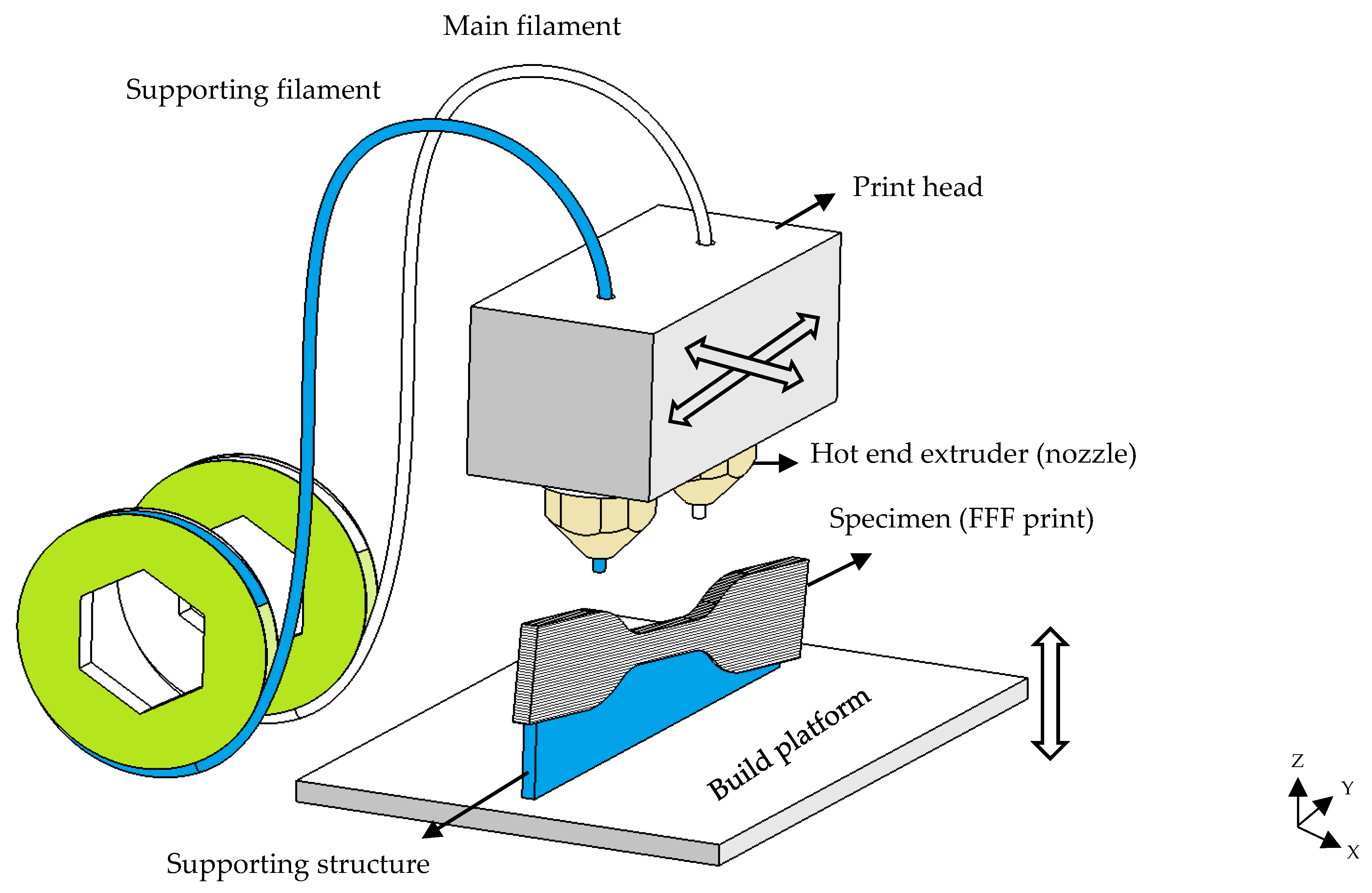
Figure 1. Schematic illustration of the FFF process.
Applsci 13 00904 g001
Figure 2. S–N curve for 3D-printed and injection-moulded ABS specimens (Adapted from S-N curves by Padzi et al. [15]. CC BY 3.0).
Applsci 13 00904 g002
Figure 3. The 3D printing parameters influencing the mechanical properties of FFF prints.
Applsci 13 00904 g003
Figure 4. Schematic illustration of 3D printing parameters: (a) infill density, infill pattern, perimeters, and raster orientation, and (b) different build orientations, layer height, and nozzle diameter.
Applsci 13 00904 g004
Figure 5. Illustration of raster orientation and loading direction in (a) compressive (b) flexural, and (c) rotating bending specimens. Since extruded filaments and the loading direction are not co-planar in the pure compression state, the raster angle is not defined for compressive specimens.
Applsci 13 00904 g005
Figure 6. Endurance limit of some plastics used as 3D printing filaments [32,33,34].
Applsci 13 00904 g006
Figure 7. Formation of internal holes (microvoids) during FFF printing of an ABS specimen. Bright lines show the path of microcracks initiated from internal holes (stress concentration areas) [35]. CC BY 4.0.
Applsci 13 00904 g007
Figure 8. Tensile fatigue cracks initiating from the shoulder area of an Ultem 9085 print (Reprinted with permission from [36]. Copyright 2016, Springer Nature).
Applsci 13 00904 g008
Figure 9. Fatigue failure profile of tensile PLA prints with a raster angle of (a) 0°, (b) 90°, and (c) 45° (Adapted with permission from [37]. Copyright 2015, Springer Nature).
Applsci 13 00904 g009
Figure 10. Fracture surface of (a) −45°/45° and (b) 0°/90° ABS specimens after failure under tensile fatigue load (Adapted with permission from [24]. Copyright 2019, Elsevier).
Applsci 13 00904 g010
Figure 11. Shearing and debonding of layers in PLA prints subjected to compression fatigue in (a) (Adapted with permission from [38]. Copyright 2021, Elsevier) and (b) (Adapted with permission from [17]. Copyright 2016, Elsevier) and (c) illustration of fatigue cracks at the layers’ interfaces (Adapted with permission from [39]. Copyright 2021, Elsevier). Cyclic compression caused the shear deformation of prints and cracking and debonding at the layers’ interfaces.
Applsci 13 00904 g011
Figure 12. (a) Orientation of infill patterns with respect to the loading direction and (b) rectilinear and honeycomb infill patterns (Adapted with permission from [67]. Copyright 2018, Elsevier).
Applsci 13 00904 g012
Figure 13. Change in the porosity and cross-sectional shape of void spaces by changing the layer height.
Applsci 13 00904 g013
Table 1. Existing standards for the fatigue testing of polymers.
StandardApplicationRef.
ASTM D7774Flexural fatigue of plastics[40]
ASTM D3479Tension–tension fatigue of polymer matrix composites[41]
ASTM D7791Uniaxial (tension or compression) fatigue of plastics[42]
ISO 13003Fatigue properties of fibre-reinforced plastics[43]
ASTM D6115Crack propagation of fibre-reinforced polymer composites under fatigue (Mode I)[44]
ISO 15850Tension–tension fatigue crack propagation[45]
ASTM E739Statistical analysis of linear or linearized stress–life (S–N) and strain–life (ε–N) fatigue data[46]
ASTM E606Strain-controlled fatigue testing[47]
ASTM D4482Tensile (extension) fatigue of rubber compounds[48]
Table 2. Review of the parametric studies carried out on the influence of 3D printing parameters on the fatigue performance of FFF prints.
TypeMatVariable Parameters *aFixed Parameters *aSpecimen StandardTesting ConditionsResultsRef
TensileABSBuild orientation: X, Y, Z
Raster angle: 0, 45, 90°
FFF printer: Stratasys DimensionISO 527-1Loading type: stress controlled
Stress level: 40, 60, 80% UTS
Loading frequency: loading (25.4 mm/min) + unloading (12.7 mm/min)
Cycles: up to 10,000
Fatigue performance (at similar stress): Y prints > X and Z prints
All raster angles produced relatively similar fatigue resistance (0° prints performed slightly better).
[53]
Infill pattern: grid (0/90°), grid (−45/45°)Infill density: 100%
FFF printer: Stratasys UPrint SE™
ISO 527-2Loading type: stress controlled
Stress level: 40, 60, 80, 90% UTS
Loading frequency: 5 Hz
Fatigue life (at same stress): grid (–45°/45°) > grid (0°/90°)
Fatigue life (at same % of UTS):
grid (0/90°) ≈ grid (−45/45°)
[24]
Raster angle: 0, 45, 90°
Infill pattern: rectilinear, grid (45/−45°)
Nozzle T: 320 °C
Platform T: 80 °C
Layer H: 0.1778 mm
Extrusion W: 0.3048 mm
Infill density: 100%
FFF printer: Stratasys Vantage-i
ASTM-D638Loading type: Stress controlled
Stress level: 45%, 60%, 75%, 90% UTS, R = 0.1 (triangular wave)
Loading frequency: 0.25 Hz
Cycles: up to 25 h (or ~175,200 cycles)
Fatigue life (at similar % UTS): grid (45°/−45°) > rectilinear (0°) > rectilinear (45°) > rectilinear (90°)[55,56]
Raster angle: 0, 45, 90°
Infill pattern:
rectilinear, grid (0/−90°), grid (15/−75°), grid (30/−60°), grid (45/−45°)
Air gap: 0 mm
Extrusion W: 0.3048 mm
Layer H: 0.1778 mm
Infill density: 100%
FFF printer: Stratasys Vantage-i
ASTM-D638Loading type: stress controlled
Stress level: 45, 60, 75, 90% UTS, R = 0.1 (triangular wave),
Loading frequency: 0.25 Hz
Cycles: up to 25h (~17,500 cycles)
Fatigue performance: grid (45/−45°) > grid (30/−60°) > grid (15/−75°) > grid (0/−90°) > rectilinear (0°) > rectilinear (45°) > rectilinear (90°)[57]
Raster angle: 0, 45, 90°
Infill pattern: rectilinear, grid (45/−45°)
Build orientation: X
Nozzle T: 320 °C
Air gap: 0 mm
Extrusion W: 0.3048 mm
Layer H: 0.1778 mm
Infill density: 100%
FFF printer: Stratasys Vantage-i
ASTM-D3479Loading type: stress controlled
Stress level: 70% UTS, R = 0.1
Loading frequency: 0.25 Hz
Fatigue performance: grid (45/−45°) > rectilinear (0°) > rectilinear (90°) > rectilinear (45°)[58]
Manufacturing method: FFF, injection moulding (IM)-ASTM-D638Loading type: stress controlled
Stress level: 40, 60, and 80% UTS, R = 0
Loading frequency: 1 Hz
Fatigue life:
IM parts > FFF parts (~41% lower fatigue life)
[15]
PLARaster angle: 0, 45, 90°Nozzle D: 0.2 mm
Infill density: 100%
FFF printer: Cube-2
ASTM-D638Loading type: stress controlled
Stress level: 50, 60, 70, 80 % UTS
Loading frequency: 1 Hz
Cycles: up to 5000 cycles
Fatigue life (at same % of UTS):
45° print > 90° print> 0° print
[37]
Raster angle: 0, 90°
Infill pattern: rectilinear, grid (0/90°)
Print T: 250 °C
Platform T: 70 °C
Nozzle D: 0.5 mm
Layer H: 0.25 mm
Print V: 80 mm/s
FFF printer: Hage 3DpA2
ASTM-D5045-99Loading type: stress controlled
Stress level: R = 0.1 (sinusoidal wave)
Fatigue performance:
rectilinear (0°) ≈ rectilinear (90°) ≈ grid (0/90°)
Due to good layer adhesion, high nozzle T, and optimum printing parameters, similar results were achieved for all samples (isotropic properties).
[20]
Raster angle: 0, 45, 90°Print T: 230 °C
Platform T: 65 °C
Print V: 100 mm/s
Infill density: 100%f
FFF printer: MakerBot Replicator 2x
ASTM-D638Loading type: stress controlled
Stress level: R = -1 (sinusoidal wave)
Loading frequency and cycles: 2 Hz up to 1000 cycles, then 5 Hz up to 10,000 cycles, then 20 Hz until failure (max: 1 million cycles)
Fatigue life: 45° print > 0° print >> 90°
Endurance limit: 45° print (10 MPa) and 0° print (5 MPa) >> 90° (0.5 MPa)
[59]
Ultem 9085Build orientation: X, Y, ZLayer H: 0.254 mm
FFF printer: Stratasys Fortus 400 mc
ASTM D638Loading type: stress controlled
Loading frequency: 5 Hz
Cycles: until failure or 2 million cycles
Fatigue life:
X print ≈ Y print > Z Print
[36]
PCUManufacturing method: FFF, injection moulding (IM)Layer H: 0.15 mm
Extrusion W: 0.3 mm
Nozzle D: 0.5 mm
Nozzle T: 225 °C
Platform T: 40 °C
Print V: 7.5–9 mm/s
Infill density: 100%
Infill pattern: rectilinear (45°)
Perimeters: 3
Build orientation: X
FFF printer: Lulzbot TAZ 5
Custom shape dog-bone (using ASTM-E606 and ASTM-D4482)Loading type: stress controlled
Loading frequency: 5 Hz
Environment: PBS bath
Cycles: until failure or 1 million cycles
Fatigue performance:
FFF parts ≈ IM parts (FFF > IM in some cases)
The fracture surfaces of FFF and IM samples were similar.
[19]
PETGRaster angle: 0, 45, 90°
Infill pattern: rectilinear, grid (45/−45°)
Layer H: 0.2 mm
Extrusion W: 0.35 mm
Nozzle T: 265 °C
Platform T: 107 °C
Air gap: 0 mm
Print V: 40 mm/s
Infill density: 100%
FFF printer: Ultimaker 3
ASTM D638Loading type: stress controlled
Stress level: 60, 70, 80, and 90% UTS, R = 0.1, (sinusoidal wave)
Loading frequency and cycles: at 1 Hz up to 10,000 cycles, then at 2 Hz until failure
Fatigue performance:
0° print > 45/−45° print > 45° and 90° prints (at high stresses)
45° print > 0° print > 45/−45° print > 90° print (at low stresses)
[60]
CompressivePLAInfill pattern: grid (0/90°), hexagonal (0°/60°/120°)
Infill density: 30%, 50%, 70%
Nozzle D: 0.4 mm
Nozzle T: 215 °C
Print V: 30 mm/s
Layer H: 0.2 mm
FFF printer: Blocks Zero (Blocktec)
Cube (ASTM D695, 12.7 × 12.7 × 25.4 mm3)Loading type: stress controlled
Stress level: 9–14.5 MPa, R = 0.1
Loading frequency: 0.25 Hz
Max. cycles: 3600
Environment: dry
Fatigue performance:
grid (0/90°) > hexagonal (0°/60°/120°)
Effect of infill density:
prints with 50% and 70% infill density resisted fatigue even after 3600 cycles, but 30% infill prints failed at early stages.
[38,61]
Infill pattern: grid (0/90°),
hexagonal (0°/60°/120°),
concentric radial (wheel like)
Nozzle D: 0.2 mm
Nozzle T: 230 °C
Print V: 90 mm/s
Layer H: 0.2 mm
FFF printer: MakerBot Replicator 2
Cylindrical (Ø = 12 mm, height = 12 mm)Loading type: stress controlled
Loading frequency: 1 Hz
Stress level: 18 to 180 N (sinusoidal wave)
Max. cycles: 10,000
Environment: submerged in PBS
Fatigue life:
grid (4400 cycles) > hexagonal (3200 cycles) > concentric radial (2500 cycles)
Hysteresis area (damping effect):
grid > hexagonal > concentric radial
[62]
Infill pattern: circular, triangularNozzle D: 0.4 mm
Infill density: 40%
FFF printer: HORI Z500D
Cube (33 × 33 × 33 mm3)Loading type: strain controlled
Loading frequency: 0.2 Hz
Strain level: 0.7–3%
Strain ratio: 0.5
Max. cycles: 10,000
Environment: dry
Fatigue performance:
circular pore pattern > triangular pattern
Fatigue damage mechanism: rapid inelastic strain accumulation at initial cycles (~600 cycles), followed by stabilizing over the residual fatigue life
[63]
Rotating bendingABSLayer H: 0.1, 0.2, 0.3 mm
Nozzle D: 0.3, 0.4, 0.5 mm
Infill density: 25, 50, 75%
Print V: 25, 30, 35 mm/sec
Infill pattern: rectilinear, honeycomb
Nozzle T: 230 °C
Platform T: 100 °C
Raster angle:45
Perimeters: 2
Solid layers: 3 layers at bottom
FFF printer: Pyramid dual extruder M®
ASTM-D7774Loading type: stress controlled
Stress level: 8–11.5 N (~28.7–41.2 MPa; sinusoidal wave)
Fatigue performance: honeycomb > rectilinear
Influence on fatigue performance:
infill density > layer h x nozzle D
(print speed and other interactions: not influential)
[64]
PLANozzle D: 0.2, 0.4, 0.6 mm
Nozzle T: 180, 210, 240 °C
Print V: 5, 10, 15 mm/s
Layer H: 0.2 mm
Perimeter: 2
Solid layers: 1 at top, 1 at bottom
Infill pattern: rectangular
Platform T:30 °C
Build orientation: horizontal
Infill density: 60%
ISO-1143Loading type: stress controlled
Stress level: 5, 10, 15, 20 MPa
Loading frequency: 100 Hz
Influence of parameters on fatigue performance *b:
nozzle T (-), nozzle D (-), print V (-)
[65]
Layer H: 0.1, 0.2, 0.3 mm
Nozzle D: 0.3, 0.4, 0.5 mm
Infill density: 25, 50, 75%
Print V: 25, 30, 35 mm/s
Nozzle T: 200 °C
Infill pattern: honeycomb
Loading type: stress controlled
Stress level: 15N force (~bending stress: 53.8 MPa)
Loading frequency: 2800 rev/min
Influence of parameters on fatigue performance *b:
infill density (+) > layer H (+) > nozzle D (+)
Print V had no significant effect.
[66]
Layer H: 0.1, 0.2, 0.3 mm
Nozzle D: 0.3, 0.4, 0.5 mm
Infill density: 25, 50, 75%
Printing speed: 25, 30, 35 mm/sec
Infill patterns: rectilinear, honeycomb
Perimeters: 2
Solid layers: 3 layers at bottom
FFF printer: Prusa i3 Steel 3D printer
ASTM-D7774Loading type: stress controlled
Stress level: 10–22N (~35.8–78.8 MPa; sinusoidal wave)
Fatigue performance: honeycomb > rectilinear
Influence on fatigue performance:
infill density > nozzle D > layer h
(print speed and other interactions: not influential)
[67]
PLA and ABSRaster angle: horizontal (0°), vertical (90°)Layer H: 0.15
Nozzle D: 0.4
Nozzle T: PLA (200 °C), ABS (245 °C)
Platform T: 60 °C
Infill density: 50%
Print V: 60 mm/s
Infill pattern: rectilinear
FFF printer: Author-M-Pro
ISO-1143Loading type: stress controlled
Stress level: bending stress 5, 10, 15 MPa (vertical prints) and 5, 10, 15, 20 MPa (horizontal prints)
Loading frequency: 100 Hz
Fatigue life:
PLA > ABS
Horizontal prints > vertical prints
[68]
PLA-8% Wood fibreLayer H: 0.2, 0.3, 0.4 mm
Nozzle D: 0.5, 0.6, 0.7 mm
Infill density: 25, 50, 75%
Infill pattern: rectilinear, honeycomb
Print V: 25, 30, 35 mm/s
Building orientation: X
Raster angle: 45°
Nozzle T: 180 °C
Platform T: 50 °C
FFF printer: PYRAMID3D Studio RepRap
ASTM-D7774Loading type: stress controlled
Stress level: 10N
Loading frequency: 2800 rev/min
Cycles: until failure
Fatigue life: honeycomb print > rectilinear print
Influence of parameters on fatigue performance *b:
layer H (+) > nozzle D (+) > infill density (+)
(print speed: not influential)
[18]
FlexuralABSRaster angle: 0, 90°
Feed rate: 2000, 4000 mm/min
Nozzle T: 200 °C
Platform T:100 °C
ASTM D7774-12ASTM D7774-12Fatigue performance:
0° print > 90° print
Influence of parameters on fatigue performance *b:
feed rate (-)
[69]
Raster angle: 0, 45, 90°
Nozzle D: 0.4, 0.6, 0.8 mm
Layer H: 0.05, 0.1, 0.15 mm
Nozzle T: 245 °C
Platform T: 90 °C
Infill density: 100%
FFF printer: Ultimaker 2+
Custom shapeLoading type: strain controlled (using shaker)
Strain level: 2 mm (sinusoidal wave)
Loading frequency: print natural frequency
Cycles: until failure
Storage modulus:
0° print > 45° print > 90° print
Nozzle D (+), layer H (+)
Fatigue performance:
0° print > 45° print > 90° print
Influence of parameters on fatigue performance *b:
working temperature (-) > building orientation > nozzle D (+) > layer H (+)
50C to 70C → cycles to failure (96500 to 31700)
[35]
PCBuild orientation: X, Y, ZNozzle T: 290 °C
Platform T:145 °C
Print V:28 mm/s
Layer H: 0.254 mm
Extrusion W: 0.508 mm
Air gap: 0 mm
Shells: 1
Infill density:100%
Infill pattern: grid (45/−45°)
FFF printer: Stratasys Fortus 400 mc
ASTM-D790 and ASTM-D7774Loading type: stress controlled
Stress level: 20, 40, 60, and 80% UTS, R = 1, 0.5
Loading frequency: 5 Hz
Fatigue performance: Y and X prints > Z print[14]
*a Nozzle D: nozzle diameter; nozzle T: nozzle temperature; platform T: platform (printing bed) temperature; layer H: layer height; extrusion W: extrusion width; print V: print speed; *b (+) means direct correlation and (-) means inverse correlation.
Table 3. Correlation between 3D printing parameters and the fatigue performance of FFF prints for different loading types based on the results extracted from the literature. Correlations: direct (↗), inverse (↘), unspecific (▬), and unstudied (blank cell).
Correlation with Mechanical Performance Under
Tensile FatigueFlexural FatigueRotating Bending FatigueCompressive Fatigue
Applsci 13 00904 i001Applsci 13 00904 i002Applsci 13 00904 i003Applsci 13 00904 i004
3D printing parametersRaster angle↘*
[20,37,53,55,57,58,59,60]

[35,69]

[68]
Infill patternCross-over > rectilinear
[55,57]
Cross-over > rectilinear
[18,64,67]
Grid > other patterns
[38,61,62]
Infill density
[18,64,66,67]

[38,61]
Layer height
[35,84]

[18,64,66,67]
Nozzle diameter
[35]

[18,64,65,66,67]
Nozzle temperature
[65]
Printer speed
[69]

[18,64,66,67]
Build orientationY > X > Z
[36,53]
Y > X > Z
[14]
Extrusion width
Perimeters
Number of shells
Solid layers
* Some studies suggest 0° as the best angle, while other studies suggest 45°. However, in all cases, by further increasing the raster angle to 90°, tensile fatigue performance decreases.
Disclaimer/Publisher’s Note: The statements, opinions and data contained in all publications are solely those of the individual author(s) and contributor(s) and not of MDPI and/or the editor(s). MDPI and/or the editor(s) disclaim responsibility for any injury to people or property resulting from any ideas, methods, instructions or products referred to in the content.