Article

Research on the Positioning Performance of GNSS with a Low-Cost Choke Ring Antenna

1
Faculty of Mechanical Engineering, Military University of Technology, 00-908 Warsaw, Poland
2
Faculty of Security, Logistics and Management, Military University of Technology, 00-908 Warsaw, Poland
*
Author to whom correspondence should be addressed.
Appl. Sci. 2023, 13(2), 1007; https://doi.org/10.3390/app13021007
Submission received: 2 December 2022 / Revised: 8 January 2023 / Accepted: 9 January 2023 / Published: 11 January 2023
(This article belongs to the Section Robotics and Automation)

Abstract

:
One of the technologies used for localization is GNSS (Global Navigation Satellite Systems), which is exposed to many phenomena, i.e., the occurrence of terrain covers, reflections of the radio waves, and the multipath nature of the radio waves in the propagation environment. To increase the resistance to environmental phenomena, special types of antennas are used, which include, among others, choke ring antennas. The article describes the design and construction of the choke ring antenna and the impact of the mentioned device on the quality of GNSS positioning. The accuracy of the constructed antenna (based on selected accuracy measures: DRMS, 2DRMS, SEP, MRSE, SAE) is calculated together with positioning errors determined for two types of antennas: choke ring antenna and the dedicated antenna supplied by the manufacturer in RTK mode. The results confirm that the designed choke ring antenna can be used for positioning without significantly losing accuracy in the RTK mode.

1. Introduction

One of the key features of all measurement systems, including GNSS (Global Navigation Satellite Systems), is the accuracy of their operation, which can be assessed based on the analysis of measurement errors. The mentioned errors can be systematic, i.e., repeated with each measurement, or can be random for individual measurements. Manufacturers try to minimize systematic errors at an early stage of design. Systematic errors include, for example, receiver clock errors, which are effectively eliminated through the use of compensation methods. On the other hand, most of the observed errors in GNSS result from the operation of random factors, the description of which requires the use of mathematical statistics methods [1,2].
The key aspect in the analysis of the operation of satellite systems is the propagation conditions of the radio signal. They are related to, among others, the following phenomena affecting the damping of radio waves: covering the wave by buildings and trees, reflections of radio waves from various types of surfaces, and multipath wave propagation [3].
The factors obscuring the horizon include, among other buildings, that are an obstacle to the propagating wave, reducing its energy level. In turn, possible reflections and multipath of the radio signal are a direct cause of radio wave fading. It is a common phenomenon, the negative impact of which can be minimized by, inter alia, the use of several transmission frequencies in the receiver, the use of the special design of antennas, or the development of data processing algorithms in the receiver [3].
Most modern GNSS receivers already use at least two transmission frequencies and have an extensive signal processing layer. They also have external antennas, which makes the development of the antenna design the most available method of minimizing the reflection and multipath phenomena among the other mentioned options [4].
Several different antennas are used in GNSS: from small patch antennas (car navigation) to complex geodetic antennas [5,6]. There are also antennas for special applications, which have mostly larger dimensions, allowing them to obtain a sealed structure and the highest possible resistance to adverse environmental phenomena [7,8,9]. These types of antennas include choke ring antennas, which enable high damping of signals arriving at low or negative elevation angles [10,11,12]. For this purpose, the discussed antennas use coaxial rings (quarter-wave chokes) with a specially selected depth (usually ¼ wavelength of the antenna operating frequency) [13]. One of the advantages of such a structure is that it prevents the transverse flow of the induced electric current, which also allows the active element of the antenna to be electrically isolated from the side walls. In addition, this type of antenna significantly increases the protection of the receiver against jamming and interference from other radio devices nearby. Their main disadvantage is usually heavy weight resulting from the need to use metal (often steel) as the material from which the ring cover is made [5].
Localized effects such as multipath result from the environment around the receiving antenna [14]. Position fix errors are mainly caused by multipath propagation of GNSS signals. Providing a clear and accurate signal to a GNSS receiver is the primary purpose of the antenna. Integrated choke ring antennas are commercially available and very expensive [15,16]. Leica, among others, publishes the results of localization scatter studies for the AR25 choke ring antenna [17], which indicate a slight standard deviation of the obtained results (Easting 1.1 [mm], Northing 1.3 [mm], Height 2.5 [mm]) and confirms the high repeatability of positioning. Research work on choke ring antennas also focuses on the design of miniaturized [10] and increasingly lighter versions of antennas [18]. Most often, choke ring antennas are composed of deep concentric rings on a flat circular metal ground plane [11]. The subject of research is also antennas of a different shape, such as trapezoidal [19]. The time and frequency-domain responses of various choke ring shielding structures are also investigated [20,21,22]. Choke ring antennas can also be used for low-cost GNSS receivers in static measurements [23]. Positioning accuracy tests were also the subject of research in the context of using smartphones as GNSS antennas placed in a choke ring [24]. In the discussed research, it was shown that the use of a choke ring type cover improves the accuracy of localization in the X, Y, and Z coordinate systems. A choke ring antenna can also be an effective tool for establishing a baseline of possible multipath error as compared to a standard beacon antenna configuration under forest canopies [25]. However, other studies have shown that the precision of GNSS signals in static measurements within typical forest stands for Central Europe with the use of a choke ring antenna is greater than the sub-meter level [26]. The influence of GNSS antenna height on pseudorange multipath was analyzed in the article [27]. Three antennas in total were analyzed: a choke ring antenna, a geodetic microstrip patch, and an antenna used for Real Time Kinematic (RTK) measurements. Multipath signals reflected from the ground were mitigated most effectively by the choke ring antenna [27]. In conclusion, no works related to the performance tests of a dedicated GNSS antenna in a version without/with a low-cost choke ring cover have been found.
One of the possible uses of choke ring antennas is the positioning of Unmanned Ground Vehicles (UGVs). Localization problems, including the application of GNSS in UGVs, are the subject of many scientific articles [28,29,30]. GNSS is used mostly as a system for determining a reference position with high accuracy. In most cases, it is important to ensure the long-term and stable operation of the GNSS signals. Mentioned high accuracy of positioning is also required, which is most often provided by the RTK mode. It is especially critical when GNSS is the only UGV location system. This technology is often used in the field, but it has several limitations related to the need for an open horizon or satellite signal interference. In a lot of cases, the use of GNSS is simply impossible, e.g., due to environmental factors (independent of humans), while the goal is to protect GNSS antennas against the phenomenon of signal multipath or simply against external interference under good visibility. The solution in such cases could be choke ring antennas; however, their use is associated with reduced visibility of the horizon, which may affect the accuracy of the system. The positioning accuracy of GNSS is the subject of scientific articles [31,32,33,34,35]. In the case of stationary tests, long-term measurements are most often used to eliminate the occurrence of random errors. In conclusion, no works related to the positioning accuracy of the GNSS with the choke ring antennas working in RTK mode on UGVs have been found.
Accordingly, the purpose of the article is to determine the influence of the low-cost choke ring antenna on the GNSS receiver positioning accuracy working in RTK mode in the environment with possible multipath effects. For comparison, the article specifies positioning errors for two types of antennas: the aforementioned choke ring antenna and the dedicated GNSS antenna supplied by the manufacturer. In this way, the possibility of using the choke ring antenna in RTK measurements was also analyzed. The positive results of the experiment will determine the possibility of using the designed antenna on UGVs.

2. Materials and Methods

A choke ring antenna cover was designed to protect the dedicated (delivered by the manufacturer) GNSS antenna from the negative effects of the signal multipath phenomenon. The research was conducted with the use of the SwiftNav DURO receiver (Figure 1) [36].
The DURO GNSS receiver was launched in 2017. It tracks the following signal frequencies: GPS L1/L2C, GLONASS G1/G2, BEIDOU B1/B2, GALILEO E1/E5b, and signals: GPS L1/L2, GLONASS G1/G2, BeiDou B1/B2, Galileo E1/E5b, SBAS (WAAS, EGNOS, GAGAN, MSAS). In addition, it has a built-in GSM modem and supports RTK formats: RTCM 3.x. [36].

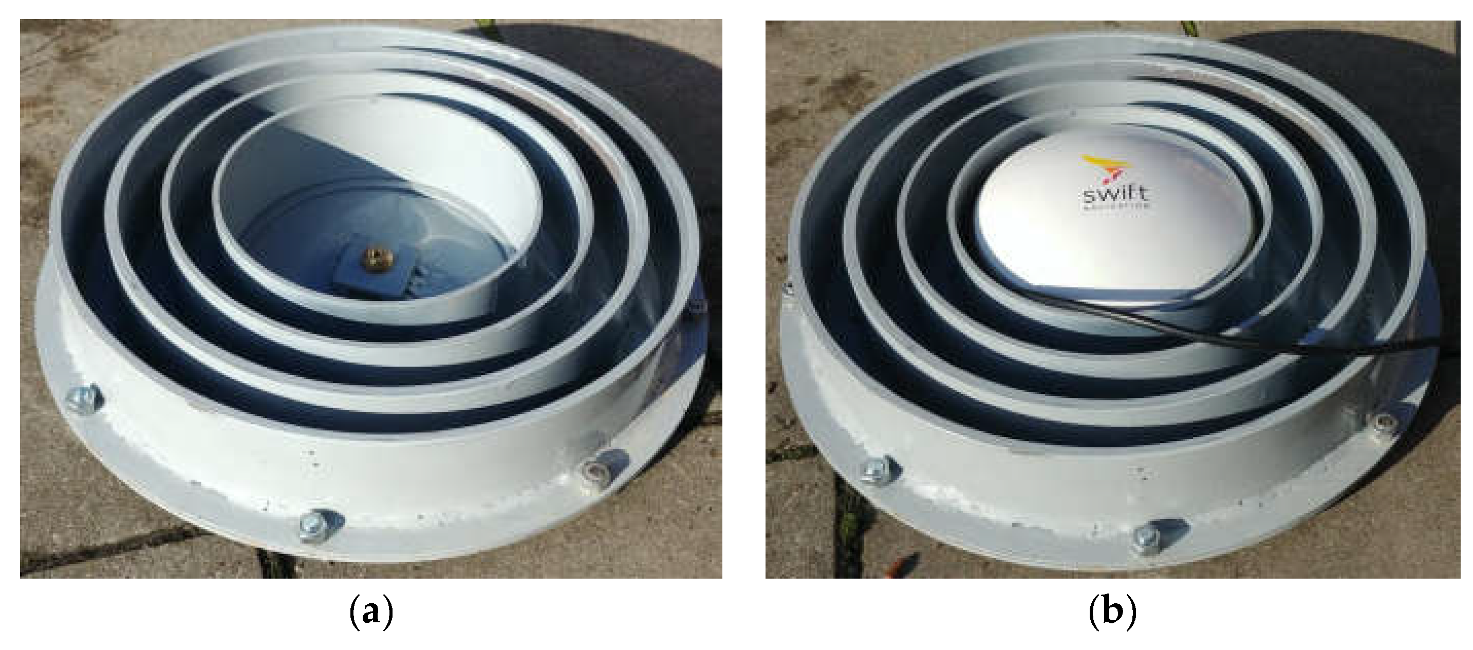
2.1. Design of Choke Ring Antenna

The design of the choke ring antenna enables preventing the signal reflected from the surface from reaching the antenna (Figure 2). The necessity to use a GNSS antenna cover is caused by the possibility of incorrect operation of the GNSS, resulting from the presence of interference, among others, generated electromagnetic waves also by other wireless technical devices operating near the antenna. Considering this and the analysis of the structure of the GNSS antenna, a design of the antenna cover was developed, consisting of four concentrically arranged steel pipes with different external diameters (Figure 2). The diameter of the pipes was selected based on the carrier wavelength L1 of the GPS signal (approx. 0.19 [m]). It was assumed that the proposed pipes would be welded to the sheet in the shape of a ring with holes for mounting bolts. The elements connected in this way (pipes and ring-shaped sheet metal) are attached to the circular base (Figure 3) through nine screw assemblies (nut-bolt), on which the GNSS system antenna will be installed.
The antenna will be attached to the base with a suitably shaped mounting element (Figure 3). This element will be welded to the base, creating a space between it and the base, into which the screw securing the antenna to the sheet will be inserted. This approach enables mounting the antenna to the designed cover without the need to disassemble the pipe. It reduces the time for the possible assembly and disassembly of the GNSS antenna with a cover. An additional advantage of this design is the isolation of the original antenna from the electric currents inducing the housing (Figure 3).
The order of mounting the designed antenna cover (Figure 4) is as follows:
  • attaching the antenna to the base (Figure 4a,b),
  • bolting the element (pipe with a ring-shaped sheet) to the base (Figure 4c,d).
The constructed choke ring antenna cover made in accordance with the design presented earlier is shown in Figure 5.
The weight of the designed GNNS antenna cover is approximately 12 [kg].

2.2. Research Methodology

The usefulness of the constructed cover of the choke ring antenna for RTK measurements was assessed by analyzing the measurements of satellite signals of the GNSS antenna in two cases: with the dedicated antenna and the choke ring antenna on a previously prepared test stand (Figure 6).
All measurements of satellite signals were performed based on the same reference station at identical points. Two long-term RTK measurements were conducted at reference points using the static technique. The points were chosen to ensure unfavorable measurement conditions (numerous horizontal curtains: the vicinity of trees, a building, and working machines equipment causing possible signal reflections). Moreover, to obtain the reference coordinates, a two-hour static session of RTK measurements was performed after prior checking of the possibility of performing RTK measurements. The results of the location of the above-mentioned points were anonymized due to the military terrain. We also assume no PCV pattern correction of GNSS in the study.
NMEA (National Marine Electronics Association) sentences were logged in the measurements with a sampling frequency of 10 [Hz]. The receiver is configured to minimize the number of necessary NMEA sentences (headers). For this purpose, two NMEA headers were used: $GPGGA (Global Positioning System Fix Data) and $GPGSA (Global Positioning DOP and active satellites) [37,38]. The $GPGGA sentences enable logging of all parameters necessary for localization, i.e., latitude, longitude, and latitude, while the $GPGSA sentences logging of statistical DOP coefficients. The information from these sentences is necessary for the subsequent conversion of the coordinate system, positioning errors, analysis of the DOP coefficient values (Section 2.3), and accuracy measures (Section 2.4).
Conversion to a metric coordinate system is necessary for the subsequent determination of positioning errors. ECEF (Earth-Centered/Earth Fixed) is an example of the mentioned coordinate system. The WGS-84 reference system was adopted for data analysis, which contains a set of parameters defining the size and shape of the Earth and the properties of its gravitational potential. The aforementioned system defines an ellipsoid used to create maps, used, inter alia, in the ECEF system [1,2,4].
The knowledge of the reference position of the GNSS antenna allows for determining the errors of the antenna positioning in the geographic coordinate system and, after conversion, in the ECEF system. In the research on the accuracy of positioning, the determination of errors in the geographic coordinate system was omitted from the determination of errors in metric systems, such as ECEF or UTM. It results from difficulties in interpreting positioning results expressed in geographical degrees.

2.3. Indicators of the Quality of the Satellite Constellation

The DOP (Dilutions of Precision) geometric factors allow the evaluation of the accuracy of the positioning in the GNSS receiver. Their value depends on the geometry of the current satellite configuration. The following DOP can be distinguished:
  • PDOP (Positional Dilution of Precision),
  • HDOP (Horizontal Dilution of Precision),
  • VDOP (Vertical Dilution of Precision) [1,2,4,39,40,41].
PDOP is the spatial factor of geometric accuracy referring to a three-dimensional position in the Cartesian system or geodetic coordinates. Another factor is HDOP, which is the plane (horizontal) coefficient of geometric accuracy referring to a two-dimensional position in a Cartesian or geodetic system. The last mentioned factor is VDOP. It describes the vertical factor of geometric accuracy related to the one-dimensional height measurement.

2.4. Accuracy Measures

The positioning accuracy of the GNSS was determined using chosen accuracy measures which are especially important in the transportation industry because of the widespread use of GNSS [42,43,44]. Therefore, it is important to assess the accuracy of GNSS-based systems carefully and to ensure that they meet the required level of performance for a given application.
In the case of measures of the accuracy of the 2D horizontal position, conversion to ENU (East, North, Up) coordinate system was performed, and the following coefficients were defined [1,2,29]:
  • DRMS (Distance Root Mean Squared)
DRMS = σ east 2 + σ north 2
  • 2DRMS (Two Distance Root Mean Squared)
2 DRMS = 2 σ east 2 + σ north 2
  • CEP (Circular Error Probable)
CEP = 0.62 σ north + 0.56 σ east
where: σeast—standard deviation of Easting, σnorth—standard error of the Northing [1,2].
In turn, in the case of the 3D position, conversion to the ECEF coordinate system was performed, and the following accuracy measures were determined [1,2,45]:
SEP (Spherical Error Probable)
SEP = 0.51 ( σ x + σ y + σ z )
  • MRSE (Mean Radial Spherical Error)
MRSE = σ x 2 + σ y 2 + σ z 2
  • 90% SAE (Spherical Accuracy Standard)
90 %   SAE = 0.51 ( σ x + σ y + σ z )
  • 99% SAE (Spherical Accuracy Standard)
99 %   SAE = 1.122 ( σ x + σ y + σ z )
where: σ—standard deviation of the satellite pseudoranges, σx—standard deviation of the x-coordinate, σy—standard deviation of the y-coordinate, σz—standard deviation of the z-coordinate [1,2].
Table 1 presents the probability values of the described accuracy measures for the 2D and 3D systems. Mentioned measure values with a higher probability value are more reliable indicators of the accuracy of the GNSS. It also explains why the comparisons of the accuracy of two or more GNSS should be made based on the same accuracy measures (different probabilities).
Moreover, there are mathematical relationships between the individual measures of positioning accuracy that enable the conversion of values among themselves [2,45].

3. Results and Discussion

As a result of the research, the time courses of geographic coordinates were recorded, i.e., latitude, longitude, and altitude for the dedicated GNSS antenna and the GNSS choke ring antenna. Then, the above-mentioned coordinates were converted to the ECEF system: ECEFx, ECEFy, and ECEFz. It enabled the determination of positioning errors: eECEFx (Figure 7), eECEFy (Figure 8), eECEFz (Figure 9), and eECEFtotal (Figure 10). In addition, the article appendix (Appendix A) presents histograms of the mentioned parameters: HDOP (Figure A1), the number of satellites in use (Figure A2), and positioning errors in the ECEF system for both antenna variants (Figure A3, Figure A4, Figure A5 and Figure A6).
Table 2 and Table 3 show the basic quantitative statistics of the following parameters: HDOP, VDOP, PDOP, number of satellites in use, ECEFX,Y,Z coordinate errors, and ECEF total errors for the dedicated antenna and choke ring antenna.
A dedicated antenna with a choke ring cover obtains by approx. 4% higher mean values of the DOP coefficients: VDOP, HDOP, and PDOP, which indicates a slightly worse geometry of the satellite constellation during the measurements. The dispersion of the values of the aforementioned parameters is particularly visible in the case of the standard deviation for HDOP, which increased by approximately 78%. The choke ring antenna has a similar average value of the number of satellites in use, approx. 14, but a larger spread of this parameter, i.e., a 26% increase in the value of the standard deviation, which influences larger fluctuations of this parameter during the measurements. The loss of positioning accuracy is visible in the analysis of the average values of the total positioning error in the ECEF system, which recorded a decrease in value of approximately 7 times. The analysis of the values of the above-mentioned parameters and errors shows that the dedicated antenna is characterized by a higher quality of positioning, i.e., lower errors. These values, however, do not apply to the positioning accuracy, and, therefore, selected measures of positioning accuracy in the 2D (Figure 11) and 3D (Figure 12) systems were determined for both variants of GNSS antennas considered in the article (described in Section 2.4).
All of the specified measures of accuracy both for the 2D (Figure 11) and 3D (Figure 12) systems indicate that the dedicated antenna is more accurate than the antenna with a choke ring cover. The use of a choke ring antenna in a 2D system is associated with a deterioration of accuracy by 51% according to the DRMS and 2DRMS measures and by 36% according to the CEP measure. Similarly, in the case of the 3D system, it is associated with a deterioration of accuracy by 41% according to the SEP measure, 48% according to the MRSE measure, and 41% according to the 90% SAS and 99% SAS measures. It should be noted that the mentioned measures differ in probability (Table 1), so the most reliable results are the 2DRMS measures for the 2D system and the 99% SAS for the 3D. In both cases, the result does not exceed 0.02 [m], which means that the choke ring antenna still maintains a high positioning accuracy, despite the observed drops in accuracy measures.

4. Conclusions

The conducted experimental studies allowed for a preliminary assessment of the impact of the use of choke ring cover on the performance of GNSS antenna during long-term operation. It is especially important in applications where long-term operation of the positioning system in conditions with the possibility of multipath effects is required.
The designed and constructed choke ring antenna cover allowed us to obtain a positioning accuracy of approximately 0.02 [m], despite the presence of higher values of the DOP parameters compared to the dedicated antenna, a similar number of satellites in use, or higher positioning errors in the ECEF system.
The obtained results confirm that the choke ring antenna can be used for positioning in non-open surroundings without a significant loss of accuracy in the RTK mode. It allows for determining the direction of future work, which could be researched on the influence of long-term external interference (EMI) on the operation of the GNSS with a choke ring antenna or the effect of the different cover material (e.g., aluminum) in the choke ring antenna on the damping of satellite signals in the context of the accuracy of the satellite system.

Author Contributions

Conceptualization, Ł.R., P.K. and K.C.; methodology, Ł.R., P.K. and K.C.; software, Ł.R.; validation, Ł.R., A.R., M.P. and T.M.; formal analysis, Ł.R., P.K. and K.C.; investigation, Ł.R., A.R. and M.P.; resources, A.R., Ł.R., M.P., P.K. and K.C.; data curation, Ł.R. and M.R.; writing—original draft preparation, Ł.R.; writing—review and editing, Ł.R., A.R., M.P., M.R. and T.M.; visualization, Ł.R., M.R. and P.K.; supervision, A.R. and T.M.; project administration, M.P. and T.M.; funding acquisition, A.R. All authors have read and agreed to the published version of the manuscript.

Funding

This work was financed by the National Centre for Research and Development under research project DOB-SZAFIR/09/A/010/01/2021 (“Inteligentny, zintegrowany system do lokalizacji, wstępnej oceny i pomocy medycznej poszkodowanym na polu walki wykorzystujący geoinformacje i sensory biomedyczne”).

Institutional Review Board Statement

Not applicable.

Informed Consent Statement

Not applicable.

Data Availability Statement

The data presented in this study are available on request from the corresponding author.

Conflicts of Interest

The authors declare no conflict of interest.

Appendix A

Figure A1. HDOP histogram: (a) GNSS antenna, (b) choke ring GNSS antenna.
Applsci 13 01007 g0a1
Figure A2. The number of satellites in use histogram: (a) GNSS antenna, (b) choke ring GNSS antenna.
Applsci 13 01007 g0a2
Figure A3. ECEFx errors histogram: (a) GNSS antenna, (b) choke ring GNSS antenna.
Applsci 13 01007 g0a3
Figure A4. ECEFy errors histogram: (a) GNSS antenna, (b) choke ring GNSS antenna.
Applsci 13 01007 g0a4
Figure A5. ECEFz errors histogram: (a) GNSS antenna, (b) choke ring GNSS antenna.
Applsci 13 01007 g0a5
Figure A6. ECEF total errors histogram: (a) GNSS antenna, (b) choke ring GNSS antenna.
Applsci 13 01007 g0a6

References

  1. Januszewski, J. GPS Satellite Systems, Galileo and Others; PWN: Warsaw, Poland, 2007. (In Polish) [Google Scholar]
  2. Narkiewicz, J. GPS and Other Satellite Navigation Systems; WKiŁ: Warsaw, Poland, 2007. (In Polish) [Google Scholar]
  3. Katulski, R. Radio Wave Propagation in Wireless Telecommunications; WKiŁ: Warsaw, Poland, 2009. (In Polish) [Google Scholar]
  4. Kruszewski, P. Satellite Navigation in Practice; KaBe: Krosno, Poland, 2016. (In Polish) [Google Scholar]
  5. Perski, A.; Wieczyński, A.; Baczyńska, M.; Bożek, K.; Kapelko, S.; Pawłowski, S. Odbiorniki GNSS w praktyce inżynierskiej. Wpływ typu anteny na jakość pomiarów GNSS. Pomiary Automatyka Robotyka 2013, 17, 106–122. (In Polish) [Google Scholar]
  6. Xu, G.; Yan, X. GPS: Theory, Algorithms and Applications; Springer: Berlin, Germany, 2016. [Google Scholar]
  7. Antennas. Available online: https://gssc.esa.int/navipedia/index.php/Antennas (accessed on 4 November 2022).
  8. GPS & GNSS Antennas. Available online: https://novatel.com/products/gps-gnss-antennas#overview (accessed on 4 November 2022).
  9. Rao, B.R.; McDonald, K.; Kunysz, W. GPS/GNSS Antennas; Artech House: London, UK, 2013. [Google Scholar]
  10. Liu, S.; Li, D.; Li, B.; Wang, F. A compact high-precision GNSS antenna with a miniaturized choke ring. IEEE Antennas Wirel. Propag. Lett. 2017, 16, 2465–2468. [Google Scholar] [CrossRef]
  11. Zhang, L.; Schwieger, V. Investigation of a L1-optimized choke ring ground plane for a low-cost GPS receiver-system. J. Appl. Geod. 2018, 12, 55–64. [Google Scholar] [CrossRef]
  12. 3D Choke Ring Antenna HX-CGX601A. Available online: https://www.orbitica.com/harxon/pdf-harxon/HX-CGX601A.pdf (accessed on 4 November 2022).
  13. Choke Ring Antenna Calibrations. Available online: https://kb.unavco.org/kb/article/choke-ring-antenna-calibrations-311.html (accessed on 4 November 2022).
  14. Kos, T.; Markezic, I.; Pokrajcic, J. Effects of multipath reception on GPS positioning performance. In Proceedings of the ELMAR-2010, Zadar, Croatia, 15–17 September 2010; IEEE: Piscataway, NJ, USA; pp. 399–402. [Google Scholar]
  15. Trimble GNSS Ti-V2 Choke Ring Geodetic Antenna. Available online: https://realtimenetworks.trimble.com/Trimble-Choke-Ring-Antenna.aspx (accessed on 4 November 2022).
  16. Leica AR25 GNSS Antenna. Available online: https://leica-geosystems.com/products/gnss-reference-networks/antennas/leica-ar25 (accessed on 4 November 2022).
  17. Leica AR25 White Paper. Available online: https://ngc.com.ua/files/PDF/Leica%20AR25%20TPA%200902%20en.pdf_Media.pdf (accessed on 4 November 2022).
  18. Emara, M.K.; Madhoun, K.; Madhoun, R.; Gupta, S. A low-cost light-weight 3D-printed choke ring for multipath mitigation for GNSS antennas. In Proceedings of the 2019 IEEE International Symposium on Antennas and Propagation and USNC-URSI Radio Science Meeting, Atlanta, Georgia, USA, 7–12 July 2019; IEEE: Piscataway, NJ, USA; pp. 721–722. [Google Scholar]
  19. Lin, D.; Wang, E.; Wang, J. New Choke Ring Design for Eliminating Multipath Effects in the GNSS System. Int. J. Antennas Propag. 2022, 2022, 1527674. [Google Scholar] [CrossRef]
  20. Scire-Scappuzzo, F.; Makarov, S.N. A low-multipath wideband GPS antenna with cutoff or non-cutoff corrugated ground plane. IEEE Trans. Antennas Propag. 2009, 57, 33–46. [Google Scholar] [CrossRef]
  21. Sawyer, D.J.; Das, S.; Diamanti, N.; Annan, A.P.; Iyer, A.K. Choke rings for pattern shaping of a GPR dipole antenna. IEEE Trans. Antennas Propag. 2018, 66, 6781–6790. [Google Scholar] [CrossRef]
  22. Davuluri, A.J.; Polepalli, S. A High Gain Ku Band Antenna with Circular Polarization Using Hybrid Choke Ring Structure. IETE J. Res. 2021, 1–10. [Google Scholar] [CrossRef]
  23. Karabulut, M.F.; Aykut, N.O.; Akpınar, B.; Topal, G.O.; Çakmak, Z.B.; Doran, B.; Zafer, A. The positioning performance of low-cost GNSS receivers in the Precise Point Positioning method. Adv. Geod. Geoinf. 2022, 71, e29. [Google Scholar]
  24. Sharma, H.; Bochkati, M.; Pany, T. Influence of the multipath mitigation on precise positioning with smartphone raw GNSS measurements. In Proceedings of the ISGNSS, Jeju, Republic of Korea, 29 October–1 November 2019; pp. 76–83. [Google Scholar]
  25. Danskin, S.; Bettinger, P.; Jordan, T. Multipath mitigation under forest canopies: A choke ring antenna solution. For. Sci. 2009, 55, 109–116. [Google Scholar]
  26. Blum, R.; Bischof, R.; Sauter, U.H.; Foeller, J. Tests of reception of the combination of GPS and GLONASS signals under and above forest canopy in the Black Forest, Germany, using choke ring antennas. Int. J. For. Eng. 2016, 27, 2–14. [Google Scholar] [CrossRef]
  27. Even-Tzur, G.; Shaked, D. GPS antenna height and its influence on pseudorange multipath. GNSS Antenna Calibration and Accuracy Assessment. In Proceedings of the FIG Working Week, Stockholm, Sweden, 4–19 June 2008; Volume 12. [Google Scholar]
  28. Typiak, R.; Rykała, Ł.; Typiak, A. Configuring a UWB Based Location System for a UGV Operating in a Follow-Me Scenario. Energies 2021, 14, 5517. [Google Scholar] [CrossRef]
  29. Yoon, B.J.; Na, J.H.; Jung, S.K.; Kim, J.H. Navigation of Unmanned Ground Vehicle (UGV) by using Dead Reckoning (DR) and global mapping optimization. In Proceedings of the 2008 International Conference on Control, Automation and Systems, Seoul, Republic of Korea, 14–17 October 2008; pp. 595–598. [Google Scholar]
  30. Rykała, Ł.; Typiak, A.; Typiak, R.; Rykała, M. Application of Smoothing Spline in Determining the Unmanned Ground Vehicles Route Based on Ultra-Wideband Distance Measurements. Sensors 2022, 22, 8334. [Google Scholar] [CrossRef] [PubMed]
  31. Li, X.; Ge, M.; Dai, X.; Ren, X.; Fritsche, M.; Wickert, J.; Schuh, H. Accuracy and reliability of multi-GNSS real-time precise positioning: GPS, GLONASS, BeiDou, and Galileo. J. Geod. 2015, 89, 607–635. [Google Scholar] [CrossRef]
  32. Dabove, P.; Di Pietra, V. Towards high accuracy GNSS real-time positioning with smartphones. Adv. Space Res. 2019, 63, 94–102. [Google Scholar] [CrossRef]
  33. Jiménez-Martínez, M.J.; Farjas-Abadia, M.; Quesada-Olmo, N. An approach to improving GNSS positioning accuracy using several GNSS devices. Remote Sens. 2021, 13, 1149. [Google Scholar] [CrossRef]
  34. Marais, J.; Nahimana, D.F.; Viandier, N.; Duflos, E. GNSS accuracy enhancement based on pseudo range error estimation in an urban propagation environment. Expert Syst. Appl. 2013, 40, 5956–5964. [Google Scholar] [CrossRef] [Green Version]
  35. Catania, P.; Comparetti, A.; Febo, P.; Morello, G.; Orlando, S.; Roma, E.; Vallone, M. Positioning accuracy comparison of GNSS receivers used for mapping and guidance of agricultural machines. Agronomy 2020, 10, 924. [Google Scholar] [CrossRef]
  36. Duro Specification and User Manual. Available online: https://support.swiftnav.com/support/solutions/articles/44001850760-duro-specification-and-user-manual (accessed on 7 June 2022).
  37. GPGGA. Available online: https://docs.novatel.com/OEM7/Content/Logs/GPGGA.htm (accessed on 4 November 2022).
  38. GPGSA. Available online: https://docs.novatel.com/OEM7/Content/Logs/GPGSA.htm (accessed on 4 November 2022).
  39. Specht, C.; Mania, M.; Skóra, M.; Specht, M. Accuracy of the GPS Positioning System in the Context of Increasing the Number of Satellites in the Constellation. Pol. Marit. Res. 2015, 2, 9–14. [Google Scholar] [CrossRef] [Green Version]
  40. Tahsin, M.; Sultana, S.; Reza, T.; Hossam-E-Haider, M. Analysis of DOP and its preciseness in GNSS position estimation. In Proceedings of the 2015 International conference on electrical engineering and information communication technology (ICEEICT), Dhaka, Bangladesh, 21–23 May 2015; pp. 1–6. [Google Scholar]
  41. Specht, M. Determination of Navigation System Positioning Accuracy Using the Reliability Method Based on Real Measurements. Remote Sens. 2021, 13, 4424. [Google Scholar] [CrossRef]
  42. Kozicki, B.; Tomaszewski, J.; Stajniak, M.; Budek, S. The method of transport forecasting in the efferta enterprise. In Proceedings of the 24th International Scientific Conference TRANSPORT MEANS 2020, Kaunas, Lithuania, 30 September–2 October 2020; Kaunas University of Technology: Kaunas, Lithuani; pp. 824–828. [Google Scholar]
  43. Kozicki, B.; Mitkow, S. A Comparative Analysis of the Number of Commodities Transported by Air in European Countries. In Proceedings of the 25th International Scientific Conference TRANSPORT MEANS 2021, Online, 6–8 October 2021; Kaunas University of Technology: Kaunas, Lithuania, 2021; pp. 734–738. [Google Scholar]
  44. Rykała, M.; Rykała, Ł. Economic Analysis of a Transport Company in the Aspect of Car Vehicle Operation. Sustainability 2021, 13, 427. [Google Scholar] [CrossRef]
  45. GPS Position Accuracy Measures. Available online: https://www.gnss.ca/app_notes/APN-029_GPS_Position_Accuracy_Measures_Application_Note.html (accessed on 4 November 2022).
Figure 1. SwiftNav Duro GNSS receiver (a) front view, (b) rear view.
Applsci 13 01007 g001
Figure 2. The designed cover for the GNSS antenna: (a) front view: 1—pipes, 2—ring-shaped plate, 3—base, 4—screw assembly, 5—GNSS antenna, (b) rear view.
Applsci 13 01007 g002
Figure 3. Attaching the antenna to the base.
Applsci 13 01007 g003
Figure 4. Mounting the housing to the antenna: 1–4 (a) step 1, (b) step 2, (c) step 3, (d) step 4.
Applsci 13 01007 g004
Figure 5. Choke ring antenna (a) cover, (b) cover with the antenna.
Applsci 13 01007 g005
Figure 6. Field test stand.
Applsci 13 01007 g006
Figure 7. The course of ECEFx errors: (a) GNSS antenna, (b) choke ring antenna.
Applsci 13 01007 g007
Figure 8. The course of ECEFy errors: (a) GNSS antenna, (b) choke ring antenna.
Applsci 13 01007 g008
Figure 9. The course of ECEFz errors: (a) GNSS antenna, (b) choke ring antenna.
Applsci 13 01007 g009
Figure 10. The course of ECEF total errors: (a) GNSS antenna, (b) choke ring antenna.
Applsci 13 01007 g010
Figure 11. Selected measures of 2D position accuracy.
Applsci 13 01007 g011
Figure 12. Selected measures of 3D position accuracy.
Applsci 13 01007 g012
Table 1. Probability of selected two-dimensional (2D) and three-dimensional (3D) accuracy measures [2,45].
PositionProbability
CEP2D50%
DRMS2D65%
2DRMS2D95%
SEP3D50%
MRSE3D61%
90% SAE3D90%
99% SAE3D99%
Table 2. Basic quantitative statistics of the analyzed parameters for the GNSS receiver with the dedicated antenna.
UnitMinimumMaximumMeanStandard DeviationRMS
VDOP-0.901.601.230.371.28
HDOP-0.701.100.810.030.80
PDOP-1.201.901.480.441.54
Satellites in use-12.0016.0014.200.6814.23
eECEFxm−2.20 × 10−22.00 × 10−28.44 × 10−44.28 × 10−34.37 × 10⁻³
eECEFym−1.63 × 10−21.37 × 10−2−1.11 × 10−34.53 × 10−34.66 × 10⁻³
eECEFzm−2.47 × 10−23.13 × 10−23.92 × 10−46.83 × 10−36.85 × 10⁻³
eECEFtotalm4.50 × 10−43.30 × 10−27.94 × 10−34.96 × 10−39.37 × 10−3
Table 3. Basic quantitative statistics of the analyzed parameters for the GNSS receiver with the choke ring antenna.
UnitMinimumMaximumMeanStandard DeviationRMS
VDOP-1.102.601.280.391.33
HDOP-0.701.200.840.150.83
PDOP-1.303.201.540.471.61
Satellites in use-12.0016.0013.860.8613.88
eECEFxm−2.76 × 10−23.54 × 10−2−9.52 × 10−47.81 × 10−37.87 × 10⁻³
eECEFym−1.48 × 10−21.42 × 10−2−2.29 × 10−43.39 × 10−33.39 × 10⁻³
eECEFzm−5.33 × 10−22.57 × 10−2−2.28 × 10−49.75 × 10−39.76 × 10⁻³
eECEFtotalm1.57 × 10−35.43 × 10−21.12 × 10−26.50 × 10−31.30 × 10−2
Disclaimer/Publisher’s Note: The statements, opinions and data contained in all publications are solely those of the individual author(s) and contributor(s) and not of MDPI and/or the editor(s). MDPI and/or the editor(s) disclaim responsibility for any injury to people or property resulting from any ideas, methods, instructions or products referred to in the content.

