Abstract
The following paper evaluates the strength properties of the critical area of the turbine rotor stage of a jet engine. This is where the blade is attached to the rotor disk. Important aspects of this issue are characteristic geometrical dimensions and operating factors, e.g., changes in rotor speed. In the article, the strength properties of the rotor stage with a trapezoidal blade–disk connection were analyzed using parametric analysis considering fluid–structure interaction (FSI). Virtual models of the compressor rotor stages were developed, including parametric blade–disk connections and discrete models for FEM (finite element method) and CFD (computational fluid dynamics) analyses. The parametric analysis was aimed at assessing selected geometric parameters in terms of their impact on the maximum stresses in the blade root. The analysis performed shows that by changing the blade’s width and thickness angles at the root, we can influence the value of the maximum stresses in the rotor stage. It was noticed that some combinations of these two parameters may negatively affect the value of the stresses in the rim.
1. Introduction
Issues related to the design of rotor systems, including compressors, are solved in many ways, including frequency analyses [1,2]. These studies, in addition to numerical analyses, are carried out by way of experiments to eliminate overlapping frequencies of components, for example, disks and blades. The work of these elements in the same frequencies leads to fatigue problems. This issue was addressed in the work of Li et al. [3]. In the paper, a decision was made to replace the standard crack simulation model with a three-dimensional comparable notch model, which turned out to be more convenient for analyzing the impact of cracking on the strength of the rotor system. Chunjie et al. [4] presented the results of a vibration analysis of the rotor stage structure with a standard lock connection. The cycle analysis method and ANSYS 2020 R2 software were used for this. The analysis showed that as the rotational speed gradually increased, the stiffness and frequency of the natural vibrations of the structures increased. The increase occurred only until a certain range of rotational speed was reached. In the analysis of rotor stages, an important issue is to estimate the service life of the structure at the time of the appearance of cracks. For this purpose, among other things, the method of damage tolerance analysis is used. Canale et al. [5] analyzed the process of crack propagation in the example of a rotor blade. The possibility of limiting crack propagation in the case of low-cycle fatigue of the construction was also checked.
Another significant issue in compressors is the stall. This phenomenon has a very negative effect on the stable operation of the compressor and significantly limits its operating range. It also has a significant impact on the service life of the rotor blades. Xinwei et al. [6] analyzed the influence of the stall pressure wave on the non-synchronous vibrations of the blades induced by it. The issue is important at an early stage of design to eliminate stall resonance. Nowadays, there are works solving the problem of strength calculations of rotor assemblies using artificial neural networks. Kozakiewicz et al. [7] presented the use of artificial neural networks to determine the stress distribution in the disk-drum stage of an aircraft turbine engine compressor. The presented algorithm made it possible to determine stress values that could be used for further mass optimization of the entire structure.
The compressor is one of the main components of the turbine engine, and the performance of the powerplant depends on its effective operation (Figure 1). This component is responsible for supplying the combustion chamber with the necessary amount of air while increasing its pressure to the required value and ensuring a uniform flow field. Currently, twin- or triple-rotor axial compressors are used in turbofan engines (three-rotor compressors are characteristic of Rolls Royce engines). There is one low- and one high-pressure compressor, and in the case of three-rotor designs, an additional medium-pressure compressor. In the case of high–bypass ratio turbofan engines, there is a single-stage fan in front of the compressors that supplies air at a specific rate and pressure to the internal and external ducts of the engine [8]. Currently, multi-stage axial compressors dominate in aviation turbine engines, in which the axial compressor rotor consists of several stages [8]. Each step consists of a support element and blades attached to it. Blades are usually made as separate elements, which allows for their easy assembly and disassembly during maintenance or repair. There are three basic structural systems of the compressor rotors’ supporting elements: drum, disk, and drum-disk. Each of these systems is still used in modern turbojet engines, both with high and low bypass ratios, in civil and military aviation, respectively.
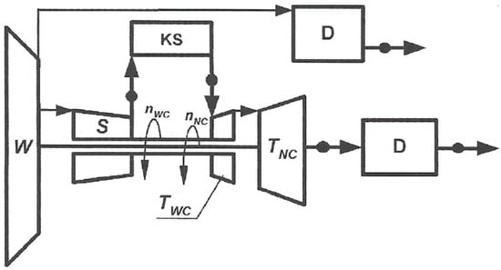
Figure 1.
Schematic diagram of a turbofan engine (W—fan, S—high-pressure compressor, KS—combustion chamber, TNC—low-pressure turbine, TWC—high-pressure turbine, D—exhaust nozzle, n—rotation speed) [8].
The critical area of the rotor stage structure of a turbojet engine is the place where the blade is attached to the disk rim. The way the blade is connected to the disk is critical for the operation of the entire compressor rotor assembly. Such an attachment must ensure the transfer of loads from centrifugal forces, aerodynamic loads, vibration loads, etc. The loads are transferred from the blade to the root and then from the root to the disk. Hence, the dimensions and shape of the attachment used have a significant impact on the stress distribution throughout the rotor stage. And, this area is the main interest of the author in the present work. The most common type of connection used in fans and rotor stages of axial compressors is a trapezoidal root with a cross-section like an isosceles trapezoid. The method of attaching the blade depends largely on the type of supporting structure. In the case of disk structures, the blades are fixed in specially made channels parallel or diagonal to the axis of rotation of the engine, and in the case of drum or drum-disk structures, in channels turned circumferentially [8,9].
The main dimensional loads in the root are centrifugal forces acting on the weight of the part of the blade located above the root (they cause tension in the cross-section and pressure of the mating surfaces at the root and the disk rim) and aerodynamic forces acting on the blade, causing bending and twisting. In the case of perimeter-fixed trapezoidal roots, the greatest tensile force acts in the 0–0 cross-section (Figure 2). The maximum tensile stresses in this section are functions of the loading force and blade dimensions:
where is the resultant loading force of the part of the blade above the section with dimensions b and c [10].
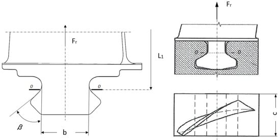
Figure 2.
Scheme of a perimeter-fixed trapezoidal root.
The Huber–von Mises–Hencky hypothesis is used to determine the maximum equivalent stresses in the rotor stage. Accordingly, the stress σe is calculated according to the following equations [8]:
or
An important aspect of the methods of designing blade connections with disks is the use of numerical methods and parametric models to optimize and assess the impact of specific variables on the strength and operation of such a structure [11,12,13,14,15,16,17,18,19]. Parameters, in this case, may be characteristic geometric dimensions and operating factors, e.g., rotational speeds or pressures affecting the distribution of aerodynamic loads acting on the blade.
Several types of loads require the use of advanced tools, such as coupled analyses examining the fluid–structure interaction (FSI). An example of the use of FSI coupling in the analysis of rotor assemblies is a publication by Sun Tao et al. [20], where the authors presented the FSI methodology in the analysis of the centrifugal compressor rotor stage and the impact of the applied coupling on the stress distribution in the rotor blade.
In the present work, the strength properties of the rotor stage with a trapezoidal blade–disk connection were analyzed using parametric analysis considering FSI. The analysis was based on the relationship between the selected geometrical parameters and the maximum stresses in the structure. The analysis algorithm is shown in Figure 3.
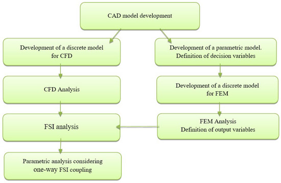
Figure 3.
Parametric analysis algorithm with FSI.
The main analysis steps in the algorithm, as shown in Figure 3, included the following: the development of a virtual model, including parametric blade–disk connection and discrete models for FEM and CFD analyses; performing numerical structural-flow analyses; and applying them to the analysis of the parametric model. In the structural analysis, mass forces resulting from the given rotational speed were assumed. In addition, the condition of the engine’s overall dimensions being unchanged was imposed, so when defining the decision variables, parameters that could change the radial dimensions of the rotor stage were not considered. The last stage of the analysis included the introduction of aerodynamic loads to the structure. In this case, a one-way FSI analysis was used, which included first determining the pressure distribution on the blade and then implementing the obtained results for structural analysis.
2. Object of Research
For the numerical research, a virtual model of the axial compressor rotor stage was developed. For this purpose, curves were used to map the scanned object, which was the blade of the high-pressure compressor of the turbine jet engine. First, the blade was modeled, and then the root was modeled. Because of the small angle of twisting within the blade, its model was limited to a few of its cross-sections, which, in this case, was sufficient to reproduce the correct geometry of the blade (Figure 4). It should be noted that in the case of modeling planes, the appropriate number of curves should be selected to obtain a non-distorted modeled surface. The high-pressure compressor support element with a disk-drum design was mapped using the available engine technical documentation.
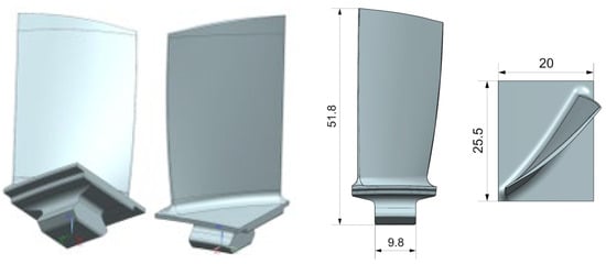
Figure 4.
Geometric model of the rotor blade and its main dimensions in millimeters.
The developed geometric model of the compressor blade was also the starting point for the preparation of a virtual model for numerical flow simulation. Considering the repeatability of elements in the rotor stage (Figure 5a) and the fact that the Fluent program allows the use of periodic boundary conditions, in the case of rotating machines, the model was limited to the construction of a small, repeating fragment of the rotor palisade (Figure 5b). These boundary conditions allow interference between successive elements of the model to be considered. In the model under consideration, the compressor stage had 68 rotor blades, so the angle of the modeled design area was 5.29°.
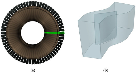
Figure 5.
Geometric model of the rotor stage with the repeating slice (marked in green) (a) and model of the calculation domain of a single rotor blade (b).
The discretization of the rotor stage structure was limited to generating a finite element grid of the slice (Figure 6a) including one blade (Figure 6b) because of the possibility of using a condition of cyclic symmetry. In addition, in sensitive areas of the structure, such as the connection area, appropriate mesh compaction was introduced (Figure 6c). The discrete model is shown in Figure 6.
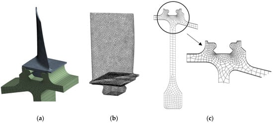
Figure 6.
Discrete model of compressor rotor stage: the repeating slice of the rotor stage model (a), FEM model of blade (b), and FEM model of disk (c).
The condition of cyclic symmetry [21,22] used in FEM calculations of rotating disks and blades allows us to shorten the calculation time. This is because the cyclically symmetrical structure contains sectors of repetitive shapes arranged circumferentially around the axis of symmetry. The FEM model of such a construction is one basic sector divided into finite elements. The remaining sectors are calculated based on the performance of the basic sector using the combined Fourier series [21]. In the analysis of rotor stages, additional difficulties are introduced by the need to consider contact on the mating surfaces of bodies. This is particularly difficult when the contact zone is not precisely known or when the contacting surfaces of the bodies may come into contact or lose contact in a way that is difficult to predict. In this type of construction, a model with nonlinear frictional contact is mainly considered. This model requires defining the value of the friction coefficient and considering the influence of the set value on the distribution of stresses and displacements.
The boundary conditions for the CFD task were given during the creation of the design area geometry and mesh generation (Figure 7). It consisted of indicating suitable surfaces in the calculation area, representing selected boundary conditions [23]: inlet (in the inlet to the compressor stage) in the boundary condition of Pressure Inlet; outlet (in the outlet from the compressor stage) in the boundary condition of Pressure Outlet; hub (disk/load-bearing structure) in boundary condition of Wall; shroud (outer cover) in boundary condition of Wall. In addition, because in the analyzed case, only the repeating element of the rotor stage was considered, periodic boundary conditions were imposed. They allowed us to consider the interference between subsequent elements of the model.
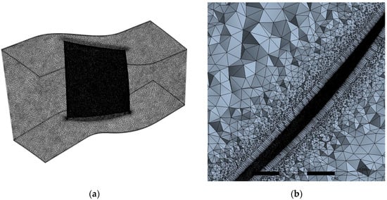
Figure 7.
Discrete model for CFD analysis: non-structural mesh (a) and non-structural mesh in cross-section (b).
3. Parametric Analysis with FSI
FSI is a multiphysical study of the interaction of fluid that flows around a solid structure, considering the effect of the reverse interaction, i.e., the impact of structural deformation on flow parameters. Fluid–structure interaction is a method that requires calculations using computational fluid dynamics (CFD) and the combination of fluid flow results with a structural analysis model. Analyses of this type should be considered wherever the flow of fluid can exert pressure as well as the thermal load on the structure. The coupling allows fluids and structural models to exchange information and shows how fluid flow can cause structure deformation (and vice versa, how structure deformations can affect flow in the ambient zone). Modeling approaches may vary depending on the degree of physical coupling between fluid and solid and the level of accuracy required. When stresses and deformations are considered, the analysis includes data provided by simulations from flow and structural analysis. The application of the appropriate FSI coupling for analysis depends on the degree of physical coupling of the solution field between the liquid and the solid [24]. Strongly physically coupled fields require strong numerical couplings. Full couplings are then used. Solution fields that are relatively independent can be solved by using a weaker numerical coupling, a one-way fluid–structure coupling.
In the parametric analysis of the blade–disk connection, one-way fluid–structure coupling was used. First, the pressure distribution on the blade was determined, and then, the resulting data were implemented for structural analysis. In addition, the influence of temperature was omitted in the analysis. This is because one of the first compressor stages made of the Inc718 alloy was being analyzed. The temperature value, in this case, would not significantly affect the properties of the material. ANSYS Workbench 2020 R2 software was used for calculations. A diagram of the one-way analysis is shown in Figure 8.
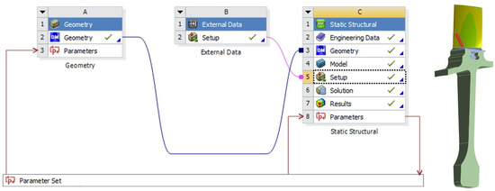
Figure 8.
One-way FSI analysis scheme in ANSYS Workbench (red line means input and output parameters, blue line means implementing geometry for structural analysis, violet line means implementing CFD results for structural analysis).
The classic design of the high-pressure compressor rotor stage was tested considering two characteristic speed ranges of turbine engines: the idle range (65% N2) and the maximum rotor speed (100% N2). The parametric analysis was carried out to evaluate selected geometrical parameters in terms of their impact on the maximum stresses in the connection. Because of the condition of maintaining the dimensions of the engine, parameters that could change the radial dimensions of the rotor stage were not considered. Parameter P1—width angle (i.e., the angle of inclination of the side surfaces of the blade root)—and Parameter P2—angle defining the thickness of the blade root were selected. They are presented in Figure 9.
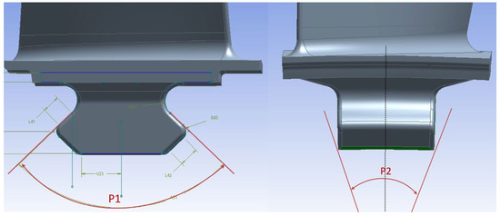
Figure 9.
Geometrical parameters of the blade root.
4. Results
4.1. Influence of the Blade Root Width Angle (P1) on the Maximum Stresses
The parameter P1 defines the angle of inclination of the side surfaces of the trapezoidal blade root. Figure 10 shows the effect of changing the value of this parameter on the maximum stresses in the rotor stage of the axial compressor at fixed values of other parameters. Parameter P1 varied from 92° to 98°.
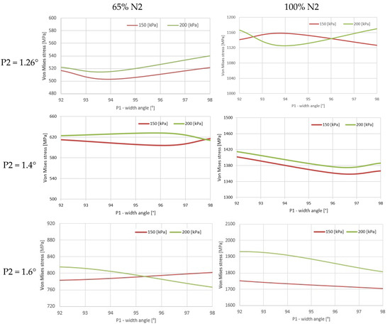
Figure 10.
Effect of P1 change on stresses.
The analyses were performed for various values of the P2 parameter. The results for three selected P2 values are shown below: 1.26°, 1.4°, and 1.6°, where 1.26° was the reference value of the parameter, resulting from the mapped real geometry of the blade root. The value of 1.6° was the maximum value of the P2 parameter that could be assumed while keeping the condition of the engine dimensions unchanged.
In the case of von Mises stresses (Figure 10) at P2 = 1.26° and 65% N2, the lowest values were obtained in the range of the variation of the breech width angle from 93° to 95°, while the highest values occurred at the angle of 98°. Depending on the value of aerodynamic loads (150 and 200 kPa), the maximum von Mises stresses were 500 and 540 MPa, respectively. The increase in rotational speed to 100% N2 resulted in an increase in the maximum stress values in stage to 1160 MPa at 150 kPa and to about 1180 MPa at 200 kPa. In the angle variation range from 93° to 95°, maximum stress values were obtained for the lower flow load (pressure 150 kPa). However, for the higher load of 200 kPa, the maximum values were obtained for the extreme values of the P1 parameter, i.e., 92° and 98°, and the lowest values were for the angle 94°.
For parameter P2 of 1.4°, the stress values did not exceed 630 MPa at idle speed. In the case of maximum rotor speed, higher values occurred for P1 = 92° at over 1400 MPa. Only after exceeding an angle of 97 degrees did the stresses at a pressure of 150 kPa increase slightly, and at 200 kPa, they began to decrease.
Increasing the value of the P2 parameter to 1.6° had a significant impact on the character of the trend and the values of stress for both assumed rotational speeds. Relatively high stress values were achieved, especially at maximum rotational speed. The lowest values of about 1700 MPa were obtained for P1 = 98°, and the highest were over 1900 MPa for P1 = 92°. These are values that significantly exceed the strength of the material used.
4.2. The Influence of the Blade Root Thickness Angle (P2) on the Maximum Stresses
The next stage of the parametric analysis included the assessment of the impact of changes in the P2 parameter (thickness angle) on the von Mises stresses in the structure, assuming constant values of the P1 parameter. The value of the P1 parameter varied from 80 to 106°, and the initial value of this parameter was 92.475°. The results (Figure 11) include two rotational speeds (65% N2 and 100% N2), three selected values of the parameter P1—92°, 94°, and 98°—and two flow loads (150 kPa and 200 kPa).
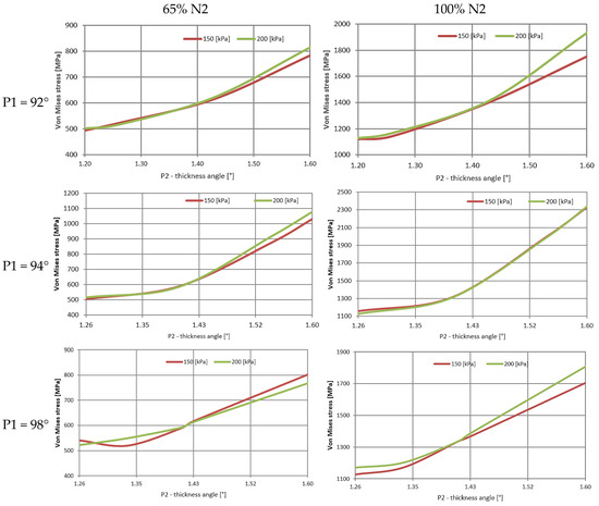
Figure 11.
Effect of P2 change on stresses.
In all considered cases, the values of stresses increased with the increase in P2. In the first of the three cases considered, where P1 = 92°, the stresses increased from about 500 MPa for P2 = 1.26° to over 800 MPa for P2 = 1.6° at 65% N2. In the case of maximum rotor speed and P2 = 1.6°, the stresses increased to almost 2000 MPa. The greatest growth occurred after the thickness angle of 1.4° was exceeded. The pressure value had an additional effect, with the greatest differences visible in the range of large values of the P2 parameter (above 1.5°).
With the value of P1 = 94°, the smallest stresses occurred for parameter P2 in the range from 1.26° to about 1.4°. After exceeding 1.4°, the stress value increased significantly. The trend of parameter changes is similar for both rotor speeds. In this case, increasing the angle of the blade root width caused an increase in stress by about 10% compared to the first case.
The value of the stresses at P1 = 98° and rotational speed of 65% N2 varied from 500 MPa to about 800 MPa. The stresses in the angle range of 1.26°–1.33° remained constant and reached 1170–1200 MPa at maximum speed (100% N2). Only after exceeding the value of P2 = 1.33° did their values reach 1800 MPa.
Summarizing the analyses carried out, it can be noted that for selected ranges of values of the P1 and P2 parameters, it is possible to find such combinations that decrease the stress values in the compressor rotor stage. In this case, small changes in the geometric dimensions affect the values of the maximum stresses. This may be important during the manufacturing and subsequent operation of the element.
4.3. Coefficient of Friction
In the analysis of the classic structure, where the rotor blade and the load-bearing element are connected at the root, friction occurring on the surfaces of contacting and cooperating elements plays an important role. In the adopted methodology, friction was considered by using the calculations for the appropriate type of contact, i.e., friction, which in ANSYS software is defined as Frictional [25]. The value of the friction coefficient defined in the program depends on the type of material from which the cooperating components are made. Usually, this value is determined experimentally, but a numerical solution can also be sought. To check how much influence the adopted value of the friction coefficient has on the maximum stresses in the compressor stage, several numerical simulations have been performed. The load was assumed to be a centrifugal force set by the appropriate rotational speed of the rotor. The results obtained are summarized in Figure 12.
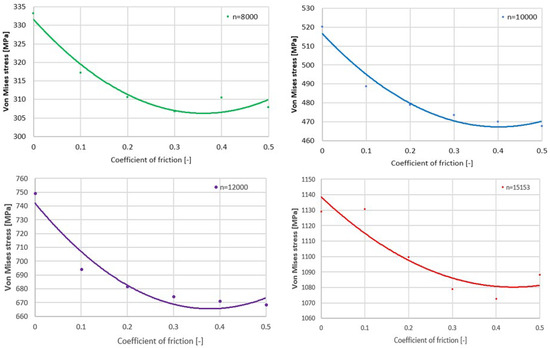
Figure 12.
Influence of the coefficient of friction on the maximum stresses at different speed ranges n (rpm).
The verification was carried out in the friction coefficient range of 0–0.5. The results are presented for four selected rotational speeds, the values of which correspond to the actual operating ranges of the turbine engine compressor rotor. In this case, the speed of 15,183 rpm corresponded to 100% N2, i.e., the maximum rotational speed of the high-pressure compressor. Trend lines had a similar course for rotational speeds less than the maximum rotor speed. With the increase in the coefficient of friction, the stress value decreased. It increased slightly after exceeding ~0.35. It is also seen that the local minimum changed with increasing speed. An increase in the coefficient of friction from 0.1 to 0.3 caused a decrease in maximum stress values by about 5%, depending on the value of rotation speed. It can also be seen that the increase in rotational speeds caused the optimal point of the curve to shift towards higher coefficients of friction. Therefore, taking the friction coefficient values in the range of 0.1–0.3 for the calculation did not critically affect the maximum values of stresses in the compressor rotor stage.
The above analysis also considered the case without friction, i.e., one in which the coefficient of friction was equal to zero (in ANSYS, the contact conditions adopted in this way are equivalent to another available type of contact, the so-called Frictionless [25]). However, it should be remembered that this is only a theoretical case. It was included to check the effects of applying such a condition in the analysis of the blade–disk connection. In an existing construction, in the blade–disk connection between adjacent surfaces, there is always at least minimal friction.
4.4. Discussion of the Results
A trapezoidal type of connection for circumferential fastening was analyzed, which is the most used type of blade–disk connection in rotor assemblies of high-pressure compressors. The conducted analysis provided information on the impact of selected combinations of geometrical parameters P1 and P2 and the coefficient of friction on the trend of changes and the values of maximum stresses in the compressor rotor stage. Numerical methods were used to analyze the issue. No experimental verification was performed at this stage. Two types of loads were considered: the mass of the rotating rotor stage and an aerodynamic load.
For lower values of P2 and lower values of rotational speeds N2, the choice of the optimum angle P1 should be related to the angle range . Considering the maximum rotor speeds, the angle P1 should be greater than . It can be concluded that the parameter P1 should have a value of about . The effect of P2 on stresses is more monotonic than P1. Aerodynamic load analysis provided information not only on the effect on stresses but also on the change in the position of the extreme load, considering the parameters studied. Analyses of the influence of the coefficient of friction showed the possibility of reducing stress by appropriate selection of this parameter. In addition, increasing the coefficient of friction in the blade–disk connection, e.g., as a result of wear or the use of special coatings with an increased value of the coefficient of friction, may adversely affect the operation and efficiency of the structure.
5. Conclusions
It can be stated that the obtained results specified the ranges in which the values of selected geometrical parameters of the blade–disk connection should be located. They provide an important indication in the field of manufacturing technology related to the need to maintain high accuracy of the connection because a small dimensional deviation significantly affects the values of maximum stresses in the rotor stage. The results of the analyses can be the basis for further work in the area of structure optimization, including parametric optimization.
It is also important to look for new configurations, such as integral structures, called BLISK (blade integrated disk) or IBRs (integral bladed rotors). These are technologically advanced compressor rotor stages in which the support element and blades are manufactured in one piece. This configuration reduces the overall dimensions and weight of the rotor. The algorithm presented in the article, with some modifications, can also be used in the analysis of this type of structure, which will also be the future scope of work.
Author Contributions
Conceptualization, O.G.-P. and A.K.; writing—original draft preparation, O.G.-P. and A.K; writing—review and editing, O.G.-P. and A.K.; supervision, A.K. and O.G.-P.; project administration, A.K. and O.G.-P.; funding acquisition, A.K and O.G.-P. All authors have read and agreed to the published version of the manuscript.
Funding
This research was funded by the Military University of Technology, Warsaw, Poland, under research project No. UGB 822/2023.
Institutional Review Board Statement
Not applicable.
Informed Consent Statement
Not applicable.
Data Availability Statement
Not applicable.
Conflicts of Interest
The authors declare no conflict of interest.
References
- Pan, H.; Wu, Y.; Zhao, T. Study on Influence of Multi-Parameter Variation of Bladed Disk System on Vibration Characteristics. Appl. Sci. 2021, 11, 3084. [Google Scholar] [CrossRef]
- Hui, M.; Di, W.; Xingyu, T.; Bangchun, W. Vibration response analysis of blade-disk dovetail structure under blade tip rubbing condition. J. Vib. Control 2016, 23, 252–271. [Google Scholar] [CrossRef]
- Li, Z.; Zhao, T.; Kou, H.; Zhang, H.; Yuan, H. Vibration Characteristics of MultiStage Blade–Disk–Shaft Integrated Structure with Three-Dimensional Crack. J. Vib. Eng. Technol. 2021, 9, 597–611. [Google Scholar] [CrossRef]
- Chunjie, W.; Shunguang, S.; Xiao, Z. Vibration analysis of blade-disc coupled structure of compressor. Front. Energy Power Eng. China 2008, 2, 302–305. [Google Scholar] [CrossRef]
- Canale, G.; Kinawy, M.; Maligno, A.; Sathujoda, P.; Citarella, R. Study of Mixed-Mode Cracking of Dovetail Root of an Aero-Engine Blade Like Structure. Appl. Sci. 2019, 9, 3825. [Google Scholar] [CrossRef]
- Xinwei, Z.; Qiang, Z.; Shuhua, Y.; Hongkun, L. Rotating Stall Induced Non-Synchronous Blade Vibration Analysis for an Unshrouded Industrial Centrifugal Compressor. Sensors 2019, 19, 4995. [Google Scholar] [CrossRef]
- Kozakiewicz, A.; Kieszek, R. Artificial Neural Network Structure Optimization in the Pareto Approach on the Example of Stress Prediction in the Disk-Drum Structure of an Axial Compressor. Materials 2022, 15, 4451. [Google Scholar] [CrossRef] [PubMed]
- Szczeciński, S.; Chachurski, R.; Kozakiewicz, A.; Balicki, W.; Głowacki, P.; Kawalec, K.; Szczeciński, J. Aircraft Turbine Engines, Construction-Operation-Diagnostics; Scientific Library of the Institute of Aviation: Warsaw, Poland, 2010; p. 428. [Google Scholar]
- Dżygadło, Z.; Łyżwiński, M.; Otyś, J.; Szczeciński, S.; Wiatrek, R. Turbine Engine Rotor Assemblies; WKL: Warsaw, Poland, 1982. [Google Scholar]
- Lipka, J. Strength of Rotating Machines; WNT: Warsaw, Poland, 1967. [Google Scholar]
- Alderson, R.G.; Tani, M.A.; Tree, D.J. Three-Dimensional Optimization of a Gas Turbine Disk and Blade Attachment. J. Aircraft. 1976, 13, 994–999. [Google Scholar] [CrossRef]
- Wang, B.P.; Wang, J.; Li, X.Z.; Han, Q.K. FE Analysis on Contact Properties between Root- Blade and Slot-Disc. Adv. Eng. Forum 2012, 2–3, 932–935. [Google Scholar] [CrossRef]
- Song, W.; Keane, A.; Rees, J.; Bhaskar, A.; Bagnall, S. Turbine blade fir-tree root design optimisation using intelligent CAD and finite element analysis. Comput. Struct. 2002, 80, 1853–1867. [Google Scholar] [CrossRef]
- Deshpande, A.S.; Keane, J.A.; Sobester, A.; Toal, J.J.D. Geometric parameterization of firtree joints in gas turbine discs considering manufacturing variability. In Proceedings of the 3rd Aircraft Structural Design Conference, Delft, The Netherlands, 8–11 October 2012. [Google Scholar]
- Meguid, S.A.; Refaat, M.H.; Papanikos, P. Theoretical and experimental studies of structural integrity of dovetail joints in aeroengine discs. J. Mater. Process. Technol. 1996, 56, 668–677. [Google Scholar] [CrossRef]
- Papanikos, P.; Meguid, S.A.; Stjepanovic, Z. Three-dimensional nonlinear finite element analysis of dovetail joints in aeroengine discs. Finite Elem. Anal. Des. 1998, 29, 173–186. [Google Scholar] [CrossRef]
- Amaresh, H.G.; Amith Kumar, S.N.D.; Basavaraj, N. Design and Analysis on Dovetail Joint of an Aero Engine Compressor Disc and Blade with Different Skew Angle. Int. J. Ignited Minds 2015, 2, 238–244. [Google Scholar]
- Beisheim, J.R.; Sinclair, G.B. On the three-dimensional finite element analysis of dovetail attachments. J. Turbomach. 2003, 125, 372–379. [Google Scholar] [CrossRef]
- Nowotarski, I. Analysis of loads in trapezoidal roots of rotating machines. WAT Bull. 1997, 6, 39–49. [Google Scholar]
- Tao, S.; Yi, W.; Rong, X. Application of FSI on turbomachinery. In Proceedings of the 2011 Asia-Pacific Power and Energy Engineering Conference, Wuhan, China, 25–28 March 2011; IEEE: Piscataway, NJ, USA. [Google Scholar] [CrossRef]
- Krzesiński, G.; Zagrajek, T.; Marek, P.; Borkowski, P. Finite element method in structural mechanics. In Solving Selected Issues Using ANSYS; Warsaw University of Technology Publishing House: Warsaw, Poland, 2015. [Google Scholar]
- Bijak-Żochowski, M.; Jaworki, A.; Krzesiński, G.; Zagrajek, T. Mechanics of Materials and Structures; Warsaw University of Technology Publishing House: Warsaw, Poland, 2013; Volume 2. [Google Scholar]
- Ansys Inc. ANSYS Fluent 12.0 User’s Guide; Ansys Inc.: Lebanon, NH, USA, 2009. [Google Scholar]
- Ansys Inc. ANSYS Fluent Fluid Structure Interaction with Ansys Mechanical; Training Materials; ANSYS: Lebanon, NH, USA, 2020. [Google Scholar]
- ANSYS System Documentation v.21. Available online: https://ansyshelp.ansys.com/ (accessed on 24 February 2023).
Disclaimer/Publisher’s Note: The statements, opinions and data contained in all publications are solely those of the individual author(s) and contributor(s) and not of MDPI and/or the editor(s). MDPI and/or the editor(s) disclaim responsibility for any injury to people or property resulting from any ideas, methods, instructions or products referred to in the content. |
© 2023 by the authors. Licensee MDPI, Basel, Switzerland. This article is an open access article distributed under the terms and conditions of the Creative Commons Attribution (CC BY) license (https://creativecommons.org/licenses/by/4.0/).