Abstract
The double arc pitch curve is a novel way for creating a non-circular gear tooth profile. Aiming at the problems of the rounding of non-integer teeth and the nonlinear equation system in the construction of double circular arc tooth profile, an active design method based on planetary gear transmission kinematics and gear-meshing theory is proposed. By studying the double arc pitch curve of the three engagement positions, combined with the uniform theory of the relative curvature of surfaces, the distribution characteristics of the solution of the nonlinear equation system are analyzed in depth, leading to the optimal solution of the characteristic parameter values of the pitch curve. Combined with UG modeling and ADAMS motion simulation, the gear engagement force and the angular velocity of the planetary gear around the center are compared and analyzed in the case of integer tooth ratio and non-integer tooth profile. The results show that the engagement force of the gear pair constructed by integer teeth is reduced by about 17%. The optimal combination of the numbers of teeth is determined by orthogonal experiments, on which trial production and hydraulic load tests are based. The results reveal that the torque of the product at a rated speed is about 2.6% higher than that of foreign prototypes, which verifies the effectiveness of the design method proposed in this paper.
1. Introduction
Double arc non-circular gear hydraulic motors have non-circular planetary gear mechanisms with fixed curvature pitch curves, replacing existing non-circular planetary gear mechanisms with continuously varying curvature-pitch curves in hydraulic motors. Non-circular gear planetary drive hydraulic motor is a new type of low-speed and high-torque hydraulic motor. This type of hydraulic motor has the advantages of simple structure, small size, light weight, wide speed range, high efficiency, and, especially, excellent resistance to the contamination of the working fluid; therefore, it has a strong product competitiveness [1]. The double circular arc non-circular gear hydraulic motor has a compact construction that transmits torque. Its application areas include printing machinery, instrumentation, mechanical stepless transmission, tobacco machinery, hydraulic motors, and other fields [2,3]. Based on the above, it is clear that non-circular gear transmission development has progressed from the research stage to the practical stage. The primary construction of the non-circular gear mechanism, as illustrated in Figure 1, is based primarily on several planetary wheels, a center wheel, and an inner gear ring.
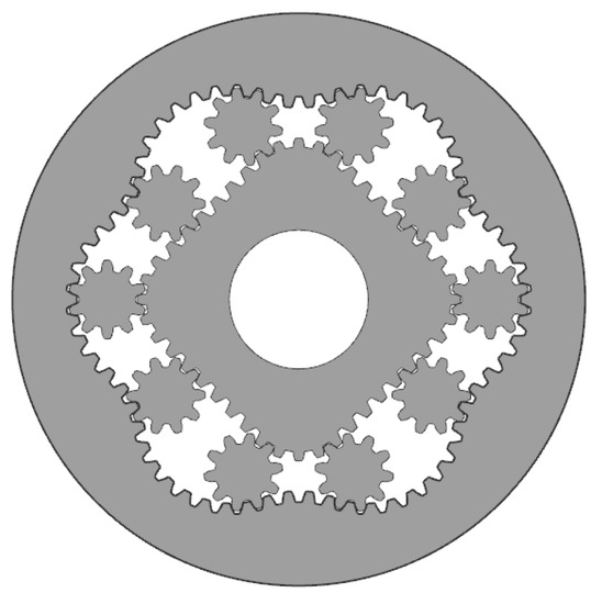
Figure 1.
Double arc non-circular gear hydraulic motor.
For the design of such hydraulic motor non-circular gears, scholars, both domestic and abroad, have undertaken extensive study, mostly using higher-order elliptic and double arc approaches for creating the pitch curve.
Li et al. [4,5,6] proposed a variable center distance class of non-circular gears different from the fixed center distance of planetary and solar wheels, which laid a solid foundation for the study of the equation of the pitch curve of non-circular gears and revealed the relationship between the structure of the motor and the displacement and output of the non-circular gear mechanism. Zhang et al. [7] studied a new design method based on a conjugate algorithm to establish the optimization algorithm of tooth profile to quickly generate the tooth profile of a non-circular gear. Tang [8] studied the parametric design of a non-circular gear hydraulic pump, verifying the SOK hydraulic motor. Liao [9] established the pitch curve design model to establish the tooth shape of the non-circular gear, which was machined by the CNC cutting method. Liu [10] studied the eccentricity of the control pitch curve parameter and analyzed the influence law of different eccentricity. The double arc pitch curve non-circular gear design was proposed by Xu [11], which determined the geometric parameters of the non-circular gear teeth and compared them with foreign prototypes for performance verification. Despite the fact that many domestic researchers have studied non-circular gears, the design of a non-circular gear tooth profile is still complicated because the pitch curve of a non-circular gear has continuously varying curvature, which makes the promotion and use of such non-circular gear hydraulic motors extremely inconvenient. The double arc pitch curve design outperforms the higher order ellipse because the curvature of the pitch curve of the non-circular gear changes only at the place where the double arcs meet, indicating that the curvature of the double arc pitch curve changes only once in the cycle [12,13].
Jie Ogawa [14,15] studied the external meshing non-circular planetary gear mechanism in 1973 and the internal meshing non-circular planetary gear mechanism in 1982. K. Michal [16] conducted a more in-depth study on non-circular gears. Deptula [17,18] presents the application of an algorithm for determining the optimal number of teeth for composite planetary gears, the application of which generates an optimal range of teeth for each gear. Brown [19] proposed the method of changing tooth profile to further improve the efficiency of non-circular gear hydraulic motors. Litwin [20] further optimized the structure of non-circular gears, making the further development of non-circular gear hydraulic motors.
Given the nonlinear features of the ideal local solution, we cannot find an optimal worldwide solution that reduces the design cost. It extends the design cycle due to numerous trials, and error procedures must be used to make the two arcs of different radius intersections transition smoothly. The transmission connection between the planetary wheel and the inner ring and center wheel to fulfill specific limitations in the design process of non-circular gear is a nonlinear issue [21,22,23,24]. As a result, a pitch circle model, for a normal meshing gear pitch curve tangent, can be proposed, which needs the combination of the geometrical and transmission relationships of non-circular gears.
According to the characteristic of numerical distribution in the nonlinear solving process, double arc non-circular gear hydraulic motor pitch curve is actively drawn. This paper proposes the method of numerical analysis and the pitch circle model, which effectively eliminates the unstable properties of a nonlinear solution and ensures that the pitch curves between them are tangential at every position. Then, the optimal double arc non-circular gear tooth profile is obtained through orthogonal experiments. From the basic simulation analysis and experimental verification, the feasibility of the method proposed in this paper is demonstrated.
2. Design of Double Arc Pitch Curve
2.1. The Model for the Nonlinear Solution
The pitch curve feature determines the type of hydraulic motor. As illustrated in Figure 2, the double arc pitch curve of the center wheel and inner gear ring may be created by arcs of various radii. The geometric formulation of the double arc non-circular gear pitch curve is briefly produced in this paper because many academics have addressed the issue in depth [25].
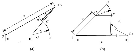
Figure 2.
The non-circular gear pitch curve. (a) Inner gear ring; (b) Center wheel.
From the above nonlinear solution, with Equation (6) as the objective function and Equations (1)–(5), (7) and (8) as constraints, the corresponding values that meet the constraints can be found.
2.2. Local Optimal Solution Processing for Nonlinear Solution Models
Iterative techniques are frequently employed to solve nonlinear equations. One of the core computing approaches is the iterative process, which includes the simple iterative approach, the Newton iterative method, and the string-cutting method [26]. The nonlinear model can only identify the ideal local solution based on the aforementioned deduction method of Equations (1)–(8). As a result, the exact answer is still impossible. Liu [27] developed a technique for measuring and separating rotational errors, as well as a systematic measurement approach for measuring and analyzing rotational errors. A data analysis technique is used to attain the goal of obtaining stable values during the pitch curve design because of the lack of optimum solution. Local optimal solutions are discovered by varying the input parameters. The distribution values of the nonlinear equations are examined by solving the nonlinear equations.
(1) Take a non-circular gear mechanism with a modulus of m = 0.75 as an example and solve for optimized values of the design variables.
(2) Assuming that the result of the calculation is X = [x1 y1 r1 x2 y2 r2], the lower bound of the solution domain is [0 0 0 0 0 0], the upper bound of the solution domain is [103 103 103 103 103 103], and the initial value of solution domain is any value.
The distribution of a numerical nonlinear solution is shown, in Figure 3, by the characteristic parameters in the process of repeated calculations several times. We found that four of the six values have a clear line except y1 and y2. In Figure 3d, the value of y2 fluctuates too much, and the density of its attributes is a maximum between 400 and 900. Despite the disorder of numerical distribution of y1, the value’s range of variation is rather limited than that of y2 in Figure 3c.
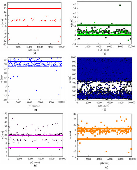
Figure 3.
Nonlinear solution of numerical distribution characteristics. (a) Distribution pattern of x1; (b) Distribution pattern of x2; (c) Distribution pattern of y1; (d) Distribution pattern of y2; (e) Distribution pattern of r1; (f) Distribution pattern of r2.
3. The Active Design of the Pitch Circle of the Integer Gear Model Building
3.1. Selection of Non-Integer and Integer Teeth
The core of the non-circular hydraulic motor is the design of the double arc pitch curve. The geometric connection between the planetary wheel, the inner gear ring, and the center wheel determines the gear-meshing relationship. As the non-circular gear rotates, the hydraulic motor’s volume is varied, providing continuous force. The final calculation result is X = [14.8790 32.7749 10.2336 11.1665 468.5719 6.3664]. The number of teeth of the arc pitch curve r1 is 27.2896. Because non-integer teeth are non-standard gears, the tooth profile design relies on calculations by MATLAB and then imports the data points into CAD to draw the non-integer tooth profile. The non-integer and integer tooth shape is shown in Figure 4.
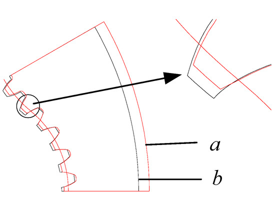
Figure 4.
Tooth shape of non-integer and integer teeth.
As shown in Figure 4, the letter a denotes integer teeth, and the letter b denotes non-integer teeth. We found that tooth thickness of non-integer teeth is larger at the point of intersection of the double arc than the integer teeth. This seriously affected the regular meshing of the gears, causing the non-circular gears to jam during the meshing process.
Due to the non-circular gear designs for non-integer teeth, the accuracy of the tooth profile is dependent on the computer’s calculation capability. Although non-circular gears with non-integer teeth tooth design are complicated, double arc non-integer teeth on the inner ring and center wheel can be replaced by cylindrical gear approximation. The number of teeth on the pitch curve is solely determined by the amplitude of the pitch curve. If the double arc non-circular gear’s pitch curve is replaced by the integer gear pitch circle, the hydraulic motor’s design issues and production costs are greatly reduced.
3.2. Pitch Circle Model of Double Arc Non-Circular Gears
A new method of double arc non-circular gear design is proposed in this paper, in which r′1 and r′2 are replaced by the original y1 and y2 to form a new double arc pitch curve. Given the preceding, the double arc pitch curve design is the critical issue of double arc non-circular gear design. The new method is the active treatment of the double arc, which ensures a smooth transition of the intersection position and the pitch curve radius of the integer teeth. Because y1 and y2 are shown to be numerically unstable during nonlinear solutions, a double arc non-circular gear pitch circle model design is proposed in this study. The benefit of the double arc non-circular gear pitch circle model is to effectively avoid the complex structure points y1 and y2, requiring just X = [x1 r′1 r1 x2 r′2 r2], which considerably increases design efficiency.
Through verification and research, it was determined that the non-integer tooth rounding on the pitch curve and the smooth transition of the double arc intersection are core to the design of the double arc pitch curve hydraulic motor. The model for the normal meshing gear pitch curve tangent can meet the tangency of the double arc at the intersection point, resulting in a smooth transition of the pitch curve while solving the non-integer tooth rounding problem. The approach satisfies the operating condition of maintaining the pitch curve tangent throughout precise non-circular gear operation, as shown in Figure 5.
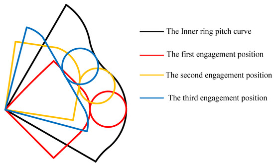
Figure 5.
Three engagement positions of double arc non-circular gears.
According to Figure 5, the three engagement positions are shown, and the work processing has a significant impact on the final performance of the non-circular gear. Through these three engagement positions, the design of the double arc pitch curve can be replaced by pitch circle of integer teeth.
The first limit position satisfies the tangency of the pitch curve, and the second is at the point where the double arcs meet, which is not considered provisionally. As shown in Figure 3, we find that the range of numerical fluctuations of the nonlinearly solved numerical Figure 3d is the largest, and the most closely related is the third engagement position. Therefore, the third engagement position is prioritized in this paper.
The value of y2 is taken multiple times with varying values, while the value of y1 remains stable since the value of y1 is more stable than that of y2. We discovered that as the value of y2 falls, the interference between the center wheel and the planetary wheel is reduced. When other values are constant, the value of y2 declines to a certain value to ensure that the third limit position of the non-circular gear pitch curve is tangential to the others, as shown in Figure 6.
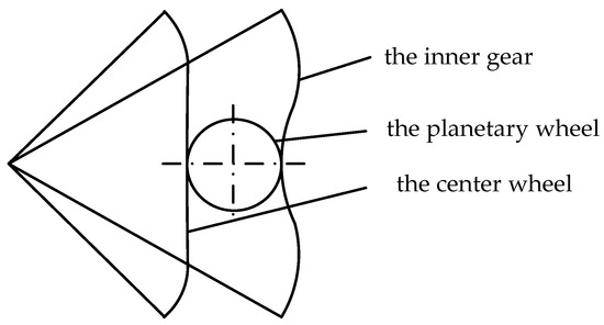
Figure 6.
The third limit position tangency verification diagram.
We found that it changes the y2 value from the initial interference to the end tangent by continuously repeating the geometric mapping of the third limit positions using different y2 values, as shown in Table 1. However, according to the graphical analysis of the data above, the value of y2 should be limited between 400 and 1000. To avoid interference, the constraints of Equation (9) should be established by the principle of relative curvature consistency of the surface, which satisfies the requirement of the tangency of non-circular gear pitch curves [28].

Table 1.
The relationship between the y2 value and the interference quantity.
—The difference of the normal curvature of the curve along the two perpendicular directions (i = 1, 2).
—The difference in the short-range deflection rate of the curve along the two perpendicular directions.
Regarding gear design, gears are designed with integer teeth instead of non-integer teeth to reduce costs. The number of teeth on the arcs of the inner ring r1 and r′1 is actively rounded based on the value of the nonlinear solution. A part of an integer gear is used as a double arc pitch curve teeth profile, which requires rescaling based on known Χ values and satisfying the constraints of the geometry of non-circular gear pitch curve design, as shown in Figure 7.
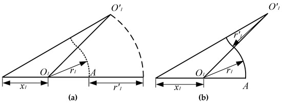
Figure 7.
Schematic diagram of the solution of the inner gear ring of the pitch circle model. (a) The start step; (b) The final step.
Figure 7 depicts three parameters of the inner ring x1, y1, and r1, redesigned by the pitch circle model, where r11, r11, and x11 become the core data of the internal ring design.
—The difference after taking an integer number of teeth for the double arc pitch curve;
x11—The x1 of the pitch circle model;
r11—The r1 of the pitch circle model;
r′11—The r′1 of the pitch circle model;
Calculating the pitch circle model parameters depends on the geometric and transmission relationships.
The latter x11, r11, and r′11 are replaced by x1, r1, and r′1 to facilitate subsequent calculations and reading. First, the ray with an angle of 30° is made from the origin. Then, a circle is drawn with the connection point between x1 and r1 as the center, O1O’1 is the sum of the radii of the double arcs r1 and r′1, as the radius makes an intersection with the ray, whose distance from the intersection point to the origin is the length of y1. The meeting and source are connected from Figure 7a to Figure 7b. The three basic parameters x1, y1, and r1 of the internal gear ring can be obtained through the pitch circle model, which can be used as the basis to achieve the design requirements of a smooth transition of the intersection point of the double arc pitch curve and the number of teeth to be rounded.
Similarly, the center wheel can be handled in the same way.
The final determination of Χ = [x1 r′1 r1 x2 r′2 r2] parameters through the model for the normal meshing gear pitch curve tangent and using the geometric constraints can be found for all the values of X = [x1 y1 r1 x2 y2 r2].
In the following procedure of the integer teeth based on the model for normal meshing gear, the problem of rounding up or down for non-integer teeth is verified using orthogonal experiments. The number of integer teeth for each section arc is determined by the orthogonal experiments, which will be addressed in the next section.
When compared to the original data, the largest change in the pitch circle model’s X value is 1.7%, while the minimum is 0.0332%. This assures that the nonlinear solution is correct. The tangency of the non-circular gear pitch curve is verified by Equation (9).
3.3. Treatment of Tooth Profile at the Point of Intersection of the Double Arc
The coordinate change’s aim is to use a coordinate change to transfer the tooth profile on the planetary wheel to the inner gear ring. The tooth profile at the intersection of the double arcs is corrected, which ensures a relatively stable mesh, as it is similar to the interpolation process in gear manufacturing. The known planetary wheel profile involute equation, through the equal arc length method, can determine the position of the planetary wheel and the rotation angle, which can be determined at the double arc intersection at the single side of the tooth profile [29].
As shown in Figure 8, the dashed circle at point C indicates the initial position of the planetary wheel, while the solid circle at point G indicates the end position of the planetary wheel. When the angle of planetary rotation is θ3, C’ indicates the angle of the planetary wheel after its rotation, and point G indicates the point of tangency after the rotation.
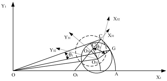
Figure 8.
Coordinate transformation diagram.
—Pole diameter of the planetary wheel;
—Pole diameter of the inner gear ring;
—Planetary wheel angle;
—Angle of rotation of the planetary wheel on the inner gear ring;
Its planetary wheels are known to be standard involute equations and coordinates of the origin.
Considering that the planetary wheel is tangential to the inner gear ring everywhere in the process of rotation, there is both rotation and translation; therefore, by transforming the matrix:
—The angle of rotation of the planetary wheel, the angle of rotation is very small, able to form the side of a tooth;
—The difference between the coordinates of the origin of and in the coordinate system of , the variation of the axis X;
—The difference between the coordinates of the origin of and in the coordinate system of , the variation of the axis Y;
By translation of the coordinates, the involute is transformed from under the coordinate system to under , and the transformation matrix is shown below:
- angle of rotation required to rotate coordinate system to coincide with coordinate system ;
—The difference between the coordinates of the origin of and in the coordinate system of , the variation of the axis X;
—The difference between the coordinates of the origin of and in the coordinate system of , the variation of the axis Y;
The unilateral profile of the teeth profile of the inner gear ring:
Through this method, we can transform the planetary wheel’s involute to the inner gear ring to design the tooth profile at the point of intersection of the double arc and to ensure a smooth transition between the planetary wheel and the inner gear ring at the intersection of the double arc. The center wheel is also transformed by this kind of treatment.
4. Modeling and Simulation of Non-Circular Gears
4.1. Determination of Basic Gear Geometric Parameters
The double arc pitch curve is created, and the Χ values are determined based on the model for the normal meshing gear. The gear geometric parameters of non-circular gears are shown in Table 2. Following the selection of the gear settings, CAXA software is used to create the corresponding pitch curves and non-circular gear tooth profiles. Then, three engagement positions are verified to ensure that the non-circular gear pitch curves are tangential at every engagement position and that the designed gears are not shown at each limit position.
Table 2.
Double arc non-circular gear geometric parameters.
The numerical geometry mapping of X = [x1 y1 r1 x2 y2 r2] after the model for normal meshing gear shows no interference in the tooth profile’s first and third limit position meshing positions, proving that the meshing gear requirements are met. This ensures the stability of the alternate meshing of the center wheel, planetary wheel, and inner gear ring, laying the foundation for the later modeling and simulation, as shown in Figure 9.
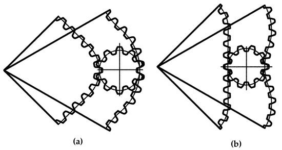
Figure 9.
Tooth profile limit position diagram. (a) The first engagement positions; (b) The third engagement positions.
CAXA and UG software were used to sketch, model, and assemble double arc non-circular gears, as shown in Figure 10. The non-circular gears include the inner gear ring and the center wheel, with only one planetary wheel completed last to facilitate numerical simulation calculations.
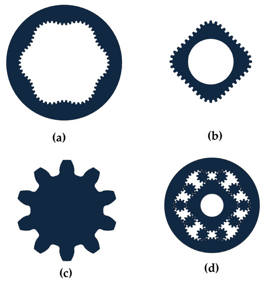
Figure 10.
3D model of a non-circular gear. (a) The inner gear; (b) The center wheel; (c) The planetary wheel; (d) The double arc non-circular gear.
In this paper, simulations are carried out using ADAMS software with the following setup:
(1) Assuming that the inner gear ring is fixed and the center wheel rotates;
(2) Considering that the end faces of the non-circular gears need the ground to be flat, the end faces of the planetary and center wheels are designed to be co-planarly constrained with the end faces of the internal gear ring;
(3) The initial rotation speed of the center wheel was set to 20°/s;
(4) The meshing contact of the gears between the planetary wheel, the center wheel and the inner gear ring is provided;
Based on the above setup, the built model is imported into ADAMS to produce the simulation results of angular velocity and engagement force, as shown in Figure 11.
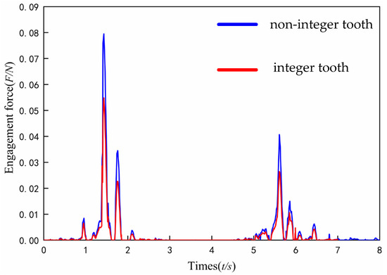
Figure 11.
The engagement force between the planetary wheel and the inner gear ring.
As shown in Figure 11, the peak of engagement force is found at 1.5 s and 5.5 s in a stage, because the principal normal vector direction of the inner gear ring at the intersection points suddenly changed at this time. It is revealed that the engagement force of integer teeth decreases by about 17% and is more stable than that of non-integer teeth at two positions.
The variation of the angular velocity of the center of the planetary wheel around the origin is shown in Figure 12.
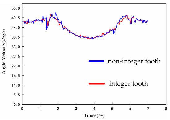
Figure 12.
Angular velocity of planetary wheel center.
As shown in Figure 12, the maximum fluctuation of angle speed is found at 1.5 s and 5.5 s in a stage, because the principal normal vector direction of the inner gear ring at the intersection points suddenly changed at this time. The difference between the maximum value of the fluctuation range of angular velocity at the intersection point, which is the difference between the maximum and minimum values of angular velocity, is significantly reduced by 17% for integer teeth compared to non-integer teeth.
4.2. Orthogonal Experiments of Non-Circular Gears Based on the Pitch Circle Model
The challenge of rounding non-integer teeth on different pitch curves requires 24 trials based on the model for normal meshing gear under a nonlinear solution. The orthogonal experimental design is a strategy for studying numerous components and levels that relies on orthogonality to select some representative points from a thorough test that are uniformly dispersed and comparable.
In the process of a trial rotation, the double arc non-circular gear jamming phenomenon is expected in non-circular tooth assembly because the planetary wheel force suddenly increases in the operation to a particular position. Building on a quantitative criterion to the peak forces on planetary wheels for non-circular gear tooth rounding is necessary. To select the best combination of teeth, the planetary rotation is allowed to run for one week, and the meshing force is measured at any moment. At the same time, the increase in the sum of two peak meshing forces of the planetary wheels in cycles is used as an indicator. Equation (18) is used as the evaluation index for the optimization results of this simulation.
Evaluation indicators for this orthogonal experiment:
—The sum of the two maximum forces in one cycle through the tooth at the point of intersection of the double arc
—Increment of adjacent cycles.
—Engagement force coefficient—the ratio of incremental engagement force of adjacent cycles.
Based on the nonlinear solution, the final result was X = [14.8790, 32.7749, 10.2336, 11.1665, 468.5791, 6.3664]. The non-circular gear hydraulic motor has four arcs to draw the corresponding tooth shape, whose results on any angles are z1 = 27.2896, z′1 = 30.3008, z2 = 16.98, and z′2 = 1115.39, respectively. Because the number of teeth of z2 is 16.98, incredibly close to 17, the teeth of z2 are directly rounded. In the subsequent design process, there are three arcs on which the number of teeth needs to be rounded, with the number of teeth on the pitch curve of each hook rounded up or down. The factors and levels of the non-circular gear orthogonal experiments are shown in Table 3.
Table 3.
Test factors and levels.
The experiment has three factors and two levels; the orthogonal experiment table was chosen to be L4(23), requiring four experiments to perform simulation experiments for four different combinations of tooth numbers on the pitch curve. The coefficient P of the engagement force for each group of measurement schemes can be obtained, as shown in Table 4.
Table 4.
Simulation calculation results of orthogonal test.
Table 4 shows that the engagement force coefficient of experiment 4 is the smallest, which indicates that the stability of the engagement force of the planetary wheel of experiment 4 is optimal. The difference in the peak force per cycle is relatively small.
The range value R reflects the effect of the tooth number factor on the non-circular gear-meshing force. The larger R-value range indicates that this factor has a more significant influence on the engagement force than others. Table 5 shows that the change in the number of z′2 teeth has the most significant effect. The change in the number of z1 teeth has a smaller impact. The number of z′1 teeth has a minor effect. The optimal combination of better levels corresponding to the number of teeth is shown in Table 5.
Table 5.
The optimal level and range of each factor.
The most optimal combination of tooth numbers is obtained with z1 = 28, z′1 = 30, z2 = 17, and z′2 = 1115. By analyzing the R values, the degree of influence on the engagement force is from the largest to the smallest: z′2, z′1, z1.
5. Discussion
The double arc non-circular gear is manufactured by the slow feeding WEDM machine, and the finished product is illustrated in Figure 13. In Figure 13, the numbers 1, 2, and 3 indicate the inner gear ring, planetary wheel, and center wheel, respectively.
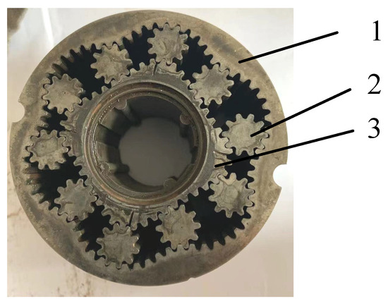
Figure 13.
Self-made double arc non-circular gear mechanism.
After machining the double arc non-circular gears, there is no jamming in rotation after the assembly of the double arc non-circular gears, and the gear backlash at every location tends to be the same; subsequently, the performance is checked on the hydraulic load platform. Table 6 compares the parameters of the prototype and the self-made product at an input pressure of 22 MPa.
Table 6.
Comparison of the performance of prototype and self-made double arc non-circular gear structures.
As shown in Table 6, the displacement per revolution and output torque of the self-made double arc non-circular gear are slightly larger than that of the prototype.
As shown in Figure 14, the emulsion pump is used as the power source, and the emulsion is used as the working medium to make the hydraulic motor rotate under a specific torque; the magnetic powder brake applies a sure torque at the output of the hydraulic engine according to the command sent by the speed collector; the torque speed sensor is installed on the magnetic powder brake to measure the torque and speed data in real-time, which is transmitted to the torque-speed power collector and displayed in real-time through the form of data. The torque characteristic curve at 300–500 RPM is shown in Figure 15.
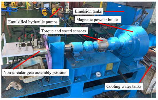
Figure 14.
Hydraulic load platform.
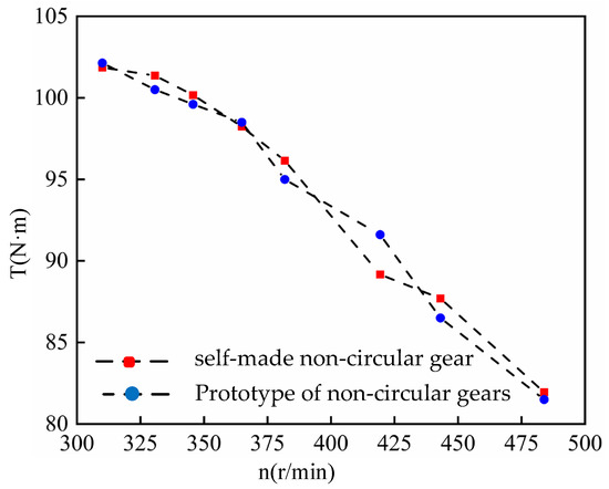
Figure 15.
Hydraulic test result.
In Figure 15, the torque characteristic curve displays that the torque of two hydraulic motors decreases as the rational speed increases. A comparison of the output torque of the homemade gear mechanism and the prototype demonstrates that the output torque is similar at the same rotational speed, with a maximum variation of 2.6%. When the operating characteristic curves of the self-made and original double arc non-circular gear mechanisms are compared, it is simple to see that the two gear mechanisms have equal operating performance in the 300 to 500 RMP working range. This shows that the design strategy provided in this paper is extremely practical.
6. Conclusions
(1) In solving the nonlinear system of equations, the curvature consistency constraint is established to effectively determine the final relative optimal solution by finding the distribution law of the optimal local solution. This suggests a new idea for the nonlinear solution of the double arc non-circular gear model.
(2) Based on the nonlinear solution of the non-circular gear double arc, the design difficulty of y1 and y2 is skillfully avoided by the construction of the model for normal meshing gear pitch curve tangent. The meshing force and angular velocity of the planetary wheel around the center at the point of intersection of the double arc are smaller for integer teeth than for non-integer teeth, and the difference in angular velocity is smaller, as demonstrated by ADMAS simulation studies.
(3) Orthogonal experiments are used to determine the numbers of teeth on the double arc. The relative curvature of the surface and the geometric mapping method used to verify the selection of the X value and the number of teeth to be rounded are both reasonable, decreasing design and manufacturing costs while also ensuring that the pitch curves are tangential and avoiding interference during the gear-meshing process.
(4) Experiments in the hydraulic load platform have demonstrated the design strategy used in this paper. Because there is no jamming in the gear-meshing process, and the gear backlash at any position tends to be the same, the hydraulic performance studies show that the self-made double arc non-circular gear product can meet the requirements of its performance in use.
Author Contributions
Conceptualization, validation, writing—original draft preparation, methodology, K.W.; investigation, formal analysis, funding acquisition, Z.G.; supervision, writing—review and editing, G.C. and M.G. All authors have read and agreed to the published version of the manuscript.
Funding
This work was supported by the National Natural Science Foundation of China (Grant nos. 51975185 and 51505129) and University’s Scientific Research Project (Grant no. ZQK202002).
Institutional Review Board Statement
Not applicable.
Informed Consent Statement
Not applicable.
Data Availability Statement
Not applicable.
Conflicts of Interest
The authors have no conflict of interest.
References
- Xiong, Z.Q.; Wu, X.T.; Gao, B.H. Parametric design of non-circular planetary gear hydraulic motors. Mach. Tool Hydraul. 2004, 5, 50–52. [Google Scholar]
- Huang, Z.D. Optimization design and analysis of stamping mechanism based on noncircular gear. Manuf. Autom. 2022, 44, 85–87+92. [Google Scholar]
- Ye, J.; Chen, J.; Yu, C.; Shen, S.; Xue, M.; Ye, Z. Study of three-joint posture-constrained single-drive non-circular gear five-bar finger mechanism. Trans. Chin. Soc. Agric. Mach. 2022, 53, 430–437. [Google Scholar]
- Li, J.S.; Li, H.M. Design of pitch curve for non-circular planetary gear mechanism with variable center distance. Mech. Transm. 1993, 17, 1–3. [Google Scholar]
- Li, J.S.; Li, H.M. Study the motion law of non-circular planetary gear mechanism with variable center distance. Mech. Transm. 1994, 18, 16–19. [Google Scholar]
- Li, J.S.; Li, H.M. Performance analysis of different types of non-circular planetary gear hydraulic motors. China Mech. Eng. 1994, 5, 21–23+77–78. [Google Scholar]
- Zhang, Q.J.; Center, Z.J.; Yang, X.Y.; Wang, K.X. Study on Optimal Design Calculation Method of Tooth Profile Curve of Noncircular Gear Train. Mod. Inf. Technol. 2022, 6, 151–155. [Google Scholar]
- Tang, D.W. Study of CADCAM System and Measurement Scheme for New Non-Circular Gear Hydraulic Motor. Ph.D. Thesis, Harbin Institute of Technology, Harbin, China, 2000. [Google Scholar]
- Liao, X. Tooth Profile Calculation and Performance Analysis of Non-Circular Planetary Gear Hydraulic Motor; Beijing Institute of Machinery Industry: Beijing, China, 2007. [Google Scholar]
- Liu, Y.P.; Fu, W.X.; Wei, Y.Q.; Li, D.W. Parametric design and motion simulation analysis of non-circular gear planetary wheel system. Mech. Transm. 2021, 45, 70–75. [Google Scholar]
- Xu, H.H.; Shen, B.M. Non-circular planetary gear mechanism with double-arc pitch curve. J. China Coal Soc. 2010, 35, 691–695. [Google Scholar]
- Shen, B.M.; Xu, H.H. Arc-arc Type Non-circular Gear Mechanism for a Hydraulic Motor. Mech. Sci. Technol. Aerosp. Eng. 2010, 30, 112–115. [Google Scholar]
- Xu, H.H.; Xu, J. Determination of the number of teeth of a non-circular planetary gear system of order 4 to 6. J. China Coal Soc. 2015, 36, 37–39. [Google Scholar]
- Ogawa, K.; Yokoyama, Y.; Koshiba, T. Studies on the Noncircular Planetary Gear Mechanisms with Nonuniform Motion. Bull. JSME 1973, 16, 1433–1442. [Google Scholar] [CrossRef][Green Version]
- Yokoyama, Y.; Ogawa, K.; Kurebayashi, S. Studies on the Noncircular Planetary Gear Mechanisms. Bull. JSME 1982, 25, 2046–2051. [Google Scholar] [CrossRef]
- Michal, K. Designing Elliptical Gears. Mach. Des. 1988, 60, 116–118. [Google Scholar]
- Deptuła, A.; Drewniak, J.; Partyka, M.A. Chosen Aspects of Analysis and Synthesis of Coupled and Complex Planetary Gears via Search and Contour Graphs Modelling; Mechanisms and Machine Science Vol. 107; Springer: Cham, Switzerland; Opole, Poland, 2022; Volume I, pp. 45–69. [Google Scholar]
- Deptuła, A.; Drewniak, J.; Partyka, M.A. The Method of Searching Trees in Determining of the Optimal Number of Wheel Teeth for a Compound Planetary Gear. In Advances in Mechanism and Machine Science, Proceedings of the IFToMM WC 2019, Krakow, Poland, 30 June–4 July 2019; Springer: Opole, Poland, 2019; pp. 2853–2862. [Google Scholar]
- Brown, A.R.; Johnson, L.C. Optimizing Non-Circular Gear Profiles for Enhanced Efficiency in Hydraulic Motors. Int. J. Fluid Power 2020, 42, 189–204. [Google Scholar]
- Litwin, T.; Smith, J.K. Advances in Non-Circular Gear Design for Hydraulic Motors. J. Mech. Eng. 2018, 25, 456–473. [Google Scholar]
- Wang, Z.; He, G.; Du, W.; Zhou, J.; Kou, Y. Application of parameter optimized variational mode decomposition method in fault diagnosis of the gearbox. IEEE Access 2019, 7, 44871–44882. [Google Scholar] [CrossRef]
- Wang, Y.; Qian, Q.; Chen, G.; Jin, S.; Yong, C. Multi-objective optimization design of cycloid pin gear planetary reducer. Adv. Mech. Eng. 2017, 1–10. [Google Scholar] [CrossRef]
- Liu, Z.P.; Su, J.X.; Deng, X.Z.; Xu, Z.J. Multi-objective optimization-based calculation and simulation of machining parameters for water motors with modified non-circular planetary gears. Mech. Transm. 2015, 39, 86–89. [Google Scholar]
- Huang, K.; Ma, J.Q.; Xia, G.C.; Zhou, H.Z.; Zhang, Z.F. Interval multi-objective optimization for the specific power of a helicopter’s main reducer planetary gear trains. J. Aerosp. Power 2017, 32, 2447–2455. [Google Scholar]
- Li, D.; Liu, Y.; Gong, J.; Wang, T. Design of a Noncircular Planetary Gear Mechanism for Hydraulic Motor. Math. Probl. Eng. 2021, 2021, 5510521. [Google Scholar] [CrossRef]
- Cui, S.H.; Liu, J.H.; Song, W.H.; Hu, S.L. Nonlinear solutions based on the proposed Newtonian method and applications. Aerosp. Shanghai 2013, 30, 16–18+64. [Google Scholar]
- Liu, F.; Liang, L.; Xu, G.H.; Hou, C.G.; Liu, D. Four-Point Method in the Measurement and Separation of Spindle Rotation Error. IEEE/A SME Trans. Mechatron. 2021, 26, 113–123. [Google Scholar] [CrossRef]
- Zeng, T. Spiral Bevel Gear Design and Machining; Harbin Institute of Technology Press: Hengyang, China, 1989. [Google Scholar]
- Li, J. Numerical Simulation and Experimental Research of Spur Cylindrical Gear Rolling; Shandong University: Jinan, China, 2007. [Google Scholar]


Disclaimer/Publisher’s Note: The statements, opinions and data contained in all publications are solely those of the individual author(s) and contributor(s) and not of MDPI and/or the editor(s). MDPI and/or the editor(s) disclaim responsibility for any injury to people or property resulting from any ideas, methods, instructions or products referred to in the content. |
© 2023 by the authors. Licensee MDPI, Basel, Switzerland. This article is an open access article distributed under the terms and conditions of the Creative Commons Attribution (CC BY) license (https://creativecommons.org/licenses/by/4.0/).