Abstract
In underground coal mines, the stability of the retracement channel in the surrounding rock is crucial for the safe and efficient retracement of the equipment and to guarantee the continuity of the retracement work. To reveal the deformation and damage mechanism of the surrounding rock of an auxiliary retracement channel (ARC) and the determination method for the reasonable spacing of two retracement channels during the end of the mining period, the deviatoric stress field in front of the working face and the change in the shape characteristics of the plastic zone in the ARC are investigated in this paper. The formation of ultimate stress equilibrium, high deviatoric stress, decreasing deviatoric stress, and low deviatoric stress environments in front of the working face during the end of mining occur successively, and the different deviatoric stress environments are the main reasons for the different shape characteristics of the plastic zone in the surrounding rock. The changes in the shape characteristics of the plastic zone correspond to the changes in the shape characteristics in the zone with deviatoric stress and exhibit the following order: full plastic deformation zone, butterfly-shaped zone, elliptical zone, and circular plastic zone. A reasonable spacing determination method for the two retracement channels is proposed: the ARC is arranged in the decreasing deviatoric stress environment, where the surrounding rock plastic zone shape is elliptical, and the ARC is relatively stable. Based on this research result, the spacing of the double retracement channels at the Lijiahao 22-116 working face was determined to be 25 m, which achieved a positive application effect and allowed the safe and efficient retracement of the working face equipment.
1. Introduction
In underground coal mining, heavy equipment such as hydraulic supports are retraced to the next working face after mining has been completed in a comprehensive working face, and the speed of the retracement is a significant factor in the efficiency of coal production [1]. Pre-excavation technology for double retracement channels arranges two channels parallel to the working face in advance near the stopping line, which allows quick retracement of the equipment through the auxiliary retracement channel (ARC) after the working face has been cut through the main retracement channel (MRC). The stability of the retracement channel surrounding rock is crucial for the safe and efficient retracement of the equipment and to guarantee the continuity of the retracement work [2]. The spacing of two retracement channels is the key factor in controlling the stability of the ARC surrounding rock. Therefore, it is beneficial in practical engineering to improve the understanding of the stress environment of the ARC under different spacings, clarify the surrounding rock deformation damage mechanism, and propose a reasonable spacing setting method.
The retracement channel is strongly influenced by mining; the surrounding rock can be seriously deformed and cause disasters, such as roof falling and coal wall spalling, at the end of the mining period [3,4,5]. It has been determined that the stress concentration from exploitation is the main reason for roadway destruction [6,7,8]. Field measurements, numerical simulations, and other means have revealed that the horizontal and vertical stresses rapidly increased after mining, and the stress environment was complex at the working face [9,10,11]. Using elastic-plastic theory, the appearance of different plastic zone shapes and the expansion laws of the roadway surrounding rock in the nonuniform stress field were analyzed, which proposed that the plastic zones in the roadway surrounding rock were butterfly-shaped, elliptical, and circular [12,13]. The mechanism of the analyzed damage to the roadway surrounding rock indicated that different surrounding rock plastic zone shapes would contribute to different degrees of deformation in the roadway [14,15].
These research results have shown the morphological variability and mechanistic complexity of the damage and deformation to roadway surrounding rock. However, the stress conditions, where the pre-excavation of the two retracement channels is located, are more complex due to the specificity of being arranged in advance and the influence from continuous mining [16,17]. Therefore, many scholars currently focus on controlling the stability of the retracement channel. The stress vector distribution in the retracement channel region is obtained through numerical simulation and field investigation [18]. LV [19] discovered the stress transfer phenomenon in the coal pillars on two sides of the retracement channel during the end of the mining period. HE et al. [20] proposed that the load on the upper coal pillars and mining disturbances caused plastic zone stress asymmetries in the retracement channel. GUO and YU [21] presented a stress release and roof cutting method to control the retracement channel stability. GU [22] investigated the mechanism of the coal pillar load transfer from the working face to the MRC, with a method to determine the widths of the coal pillars. Nevertheless, there are few studies on the stressful environment and surrounding rock deformation damage in the ARC during mining, which makes it more challenging to control the surrounding rock stability in the ARC.
The purpose of this work is to reveal the deviatoric stress field in front of the working face during the end of the mining period, analyze the change in the shape characteristics of the plastic zone in the ARC in different stress environments, propose a method to determine the reasonable spacing of the pre-excavation for double retracement channels based on the stability of the ARC, and reduce the width of the protective coal pillars while ensuring the ARC surrounding rock stability. The objective is to avoid the waste of mine resources and complete equipment retracement from the working face, safely and efficiently.
2. Engineering Background
2.1. Engineering Situations
Lijiahao Mine is in Hohhot, in the Inner Mongolia Autonomous Region of China. The 22-116 comprehensive mining working face is mainly used to mine the 2-2 coal seam. A schematic diagram of the working face layout is shown in Figure 1. To quickly transfer the hydraulic supports and other heavy equipment to the next working face after the mining has been completed, double retracement channels are prearranged near the stopping line at the back of the working face. The retracement channel near the working face is the MRC, the other is the ARC.
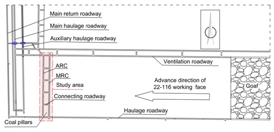
Figure 1.
Schematic diagram of the 22-116 working face layout.
When the working face cuts through to the MRC at the end of the mining period, the equipment is transferred to the ARC via the connection roadway and, subsequently, to the next working face. The pre-excavation technology used for the two retracement channels saves equipment retracement time and improves coal mining efficiency.
2.2. Problems in Production
The problem faced by the pre-excavation technology used for the two retracement channels is that the ARC is influenced by mining during the end of the mining period. This influence results in severe deformation and damage to the ARC and challenges the equipment’s safe and efficient reinforcement. The MRC in the 22-116 working face is supported by a stacking support, and the ARC is supported by a bolt and a cable anchor.
During the end of mining, if the two retracement channels are too closely arranged, the ARC is strongly influenced by the mining and causes serious deformation and damage to the channel, and the equipment cannot achieve smooth retracement. This outcome will directly decrease the retracement efficiency and cause economic loss when the ARC must be repaired, which will also impact the layout of the next working face. If the spacing of two retracement channels is too wide, many of the coal pillars left behind cannot be recovered, which causes a waste of coal resources.
2.3. Geological Conditions
The 22-116 working face in the Lijiahao Mine is mainly used for mining the 2-2 medium coal seam, with a tendency length of 300 m, a strike length of 2406 m, and an average burial depth of 185 m. In the working face area, the average thickness of the coal seam is 2.01 m. The seam is relatively stable with a more significant thickness variation, and it is thicker in the southern part of the survey area. The coal seam dips from 0~3°, which is a near-horizontal coal seam, and contains 0~2 layers of dirt band, part of which contains one layer of dirt band. The coal seam structure is simple and stable. The geological columnar section of the 22-116 working face is shown in Figure 2.
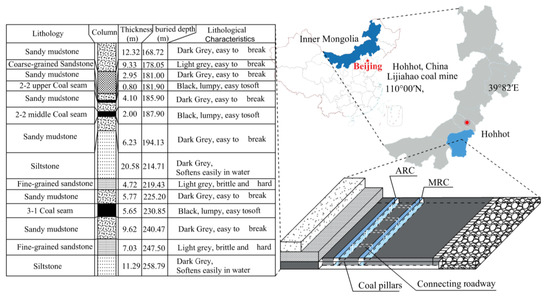
Figure 2.
Stratigraphic column of the 22-116 working face.
The floor lithology is mainly composed of sandy mudstone and siltstone, which have low mechanical strength and easily soften and deform when encountering water. The roof lithology is mainly composed of sandy mudstone and coarse-grained sandstone. From the mechanical test results, the compressive strength is very low, mainly less than 30 MPa, while the shear and tensile strengths are even lower. The rocks in the coal seam floor and roof are mostly soft, and some of the rocks are semihard or hard rocks. The equipment retracement adopts the pre-excavated double retracement channel technology. The ARC section dimension is 5.4 m × 2.6 m, and the MRC section dimension is 5.2 m × 2.4 m.
3. Analysis of the Plastic Zone Characteristics in the Rock Surrounding the Auxiliary Retracement Channel
3.1. Evolution of the Shape of the Plastic Zone in the Nonuniform Stress Field in the Roadway Surrounding Rock
3.1.1. Mechanical Model of a Nonuniform Stress Field in a Circular Roadway
Based on the current research on the elastic-plastic deformation of the hole, the damage range of the roadway is quantified by mechanical-mathematical methods, which adopt the circular hole plane from the strain model. The stress field under the mining influence is simplified to a planar axisymmetric, nonuniform hydrostatic pressure condition. A bidirectional, nonuniform pressure circular roadway model is established, as shown in Figure 3.
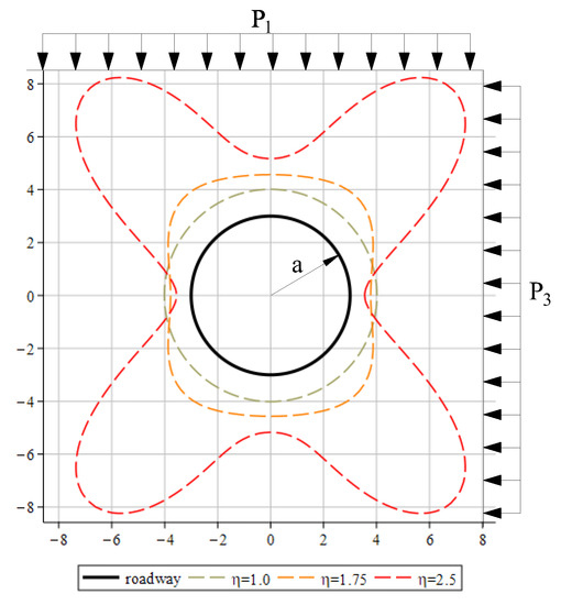
Figure 3.
Computational model of the surrounding rock plastic zone in a bidirectional, nonuniform stress circular roadway.
In the model, the radius of the circular roadway is a, the coordinates of any point in the polar coordinate system are (r, θ), the nonuniform stress field around the circular roadway is represented using the regional principal stress field, P1 is the regional maximum principal stress, and P3 is the regional minimum principal stress.
A bidirectional, nonuniform stress condition is called a deviatoric stress environment, which uses the ratio η of P1 to P3 to reflect the degree of nonuniform stress distribution, as shown in Equation (1).
3.1.2. Evolution of the Shape of the Surrounding Rock Plastic Zone in the Deviatoric Stress Environment
In the literature, the bidirectional, nonuniform stress circular roadway model is analyzed, which combines the stress expression at a point in the roadway surrounding rock using polar coordinates in elastic mechanics and the Mohr–Coulomb damage criterion to derive the implicit equation for the boundary of the plastic zone in the circular roadway in a nonuniform stress field [23]. The plastic zone boundary location in the roadway can be calculated for the given roadway specifics and surrounding rock stress conditions, as shown in Equation (2).
Equation (2) shows that the surrounding rock plastic zone boundary in a circular roadway in a nonuniform stress field is mainly related to the roadway radius a, the regional principal stress environment (P1, P3, and η), and the rock lithology (φ: internal friction angle, C: cohesion). For the same lithology, the degree of nonuniformity in the stress field distribution (η) is the critical factor for determining the damage form and size of the roadway surrounding rock in a partial stress environment [24].
The following parameters are used in building the FLAC3D numerical simulation model: the circular roadway has a radius of 3 m, the mechanical properties of the surrounding rock are C = 3 MPa and φ = 25°, and the minimum principal stress P3 is 20 MPa. Under these conditions, Equation (2) was prepared using the MAPLE2020 mathematical software to calculate the roadway plastic zone boundary with a change in the degree of the nonuniform stress distribution (η). The evolution of the size and shape of the plastic zone in the surrounding rock in the roadway is shown in Figure 4.
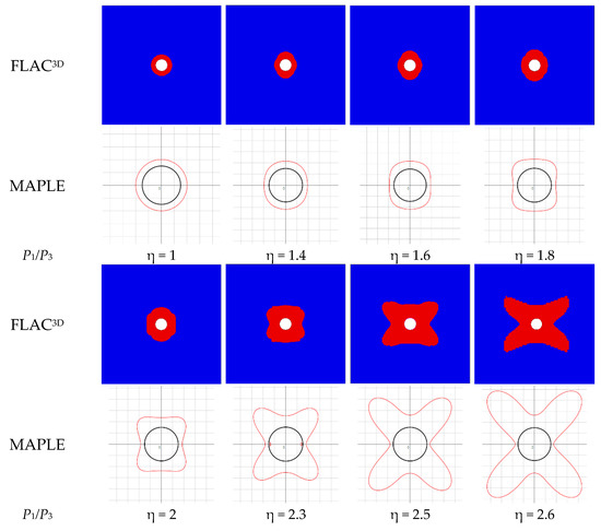
Figure 4.
Evolution of the plastic zone calculated by simulation.
With an increase in η, the surrounding rock plastic zone shape from the FLAC3D simulation and MAPLE calculation indicates the development pattern of the circular–elliptical–butterfly shaped, and the maximum boundary range of the plastic zone increases with the change in shape. When η = 1, the roadway is in a bidirectional equal stress condition, the plastic zone is not large, it is uniformly distributed in the surroundings of the roadway, and the form is a regular circular shape. With an increase in η, the plastic zone begins to expand above the roof and below the floor in the roadway. When η increases, the plastic zone shape develops from circular to elliptical, where the ellipse’s long axis is in the direction of P3. When η > 1.8, the growth rate of the plastic zone in the four corners of the roadway is larger than the two sides of the roadway, which is expanded by a significant amount in the four corners of the roadway, and the shape develops from elliptical to butterfly shaped. When η > 2.3, the shape is like a butterfly, and any further minor increases in η will significantly expand the plastic zone near the angular parallels in the P1 and P3 directions.
3.1.3. Relationship between the Principal Stress Direction and the Shape Characteristics of the Plastic Zone
When the roadway is in a deviatoric stress environment, the plastic zone shape changes mainly due to the nonuniform stress distribution. With increasing η, the plastic zone evolves in the order of circular–elliptical–butterfly shaped. During the evolution of the shape, the plastic zone extension is mainly near the angle bisector between the directions P1 and P3. Therefore, when the directions of the maximum and minimum principal stress change, the expansion of the plastic zone in the surrounding rock will also change location.
A butterfly-shaped plastic zone in the roadway surrounding rock in a deviatoric stress environment is shown in Figure 5a. When P1 is in the vertical direction and P3 is in the horizontal direction, the butterfly-shaped plastic zone significantly expands at the roadway’s four corners. If a certain deflection angle occurs in the direction when applying P1 and P3, the location where the expansion of the butterfly-shaped plastic zone occurs also has the same deflection angle.
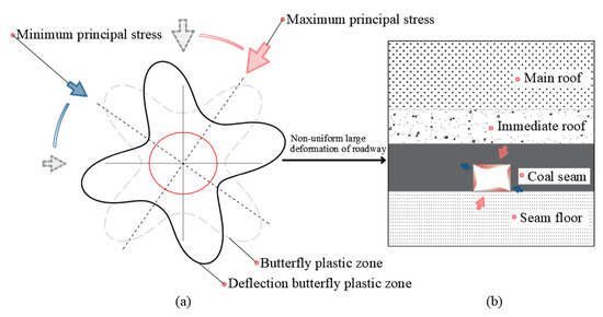
Figure 5.
Deflection of the butterfly-shaped plastic zone in the roadway surrounding rock.
The plastic zone expansion location in the roadway is near both sides and the floor and roof plates after the principal stress has been deflected. The plastic zone near the roof is deeper than the effective range of the available anchor bolts and cable supports. Figure 5b shows that the roadway disaster manifests as a large nonuniform deformation of the surrounding rock and a large amount of roof subsidence, and the anchor bolts and anchor cable support failure appear to result in roof caving.
3.2. Migration Law of the Mining Stress Field in front of the Working Face
After the working face has been mined, the bearing capacity of [6,9,25] the waste rock collapsed in the goaf is reduced. The self-weight stress of the overlying strata is transferred to the coal body in front of the working face, which results in the stress concentration phenomenon after the stress redistribution. The vertical stress starts from less than the original rock stress (γH) and rapidly increases to KγH (K is the abutment pressure coefficient, 3~5), which reaches the maximum value and decreases as it moves away from the working face until it decreases near γH. The horizontal stress increases from 0 to close to γH and, subsequently, remains unchanged. At the location far from the working face, the vertical and horizontal stress are γH, where the roadway is in the original rock stress state and is almost unaffected by mining.
Figure 6 shows the stress field migration law of mining in front of the working face. The retracement channels are prearranged near the stop line when the working face is mined, away from the working face unaffected by the mining stress. The mining stress field migrates with the working face as the working face is mined. The coal body in front of the working face is always under the influence of concentrated stresses. At the end of mining, the retracement channel gradually enters the influence range of the mining stress field, which gradually increases the stress on the retracement channel. After the working face cuts through the MRC, the spacing of the two retracement channels will determine the degree to which the mining stress field influences the ARC.
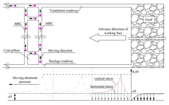
Figure 6.
Migration law of the mining stress field in front of the working face.
3.3. Shape Characteristics of the Plastic Zone in the Auxiliary Retracement Channel during the End of the Mining Period
Under the influence of mining stress, the maximum principal stress near the working face is similar to the vertical stress size change law, and the minimum principal stress is similar to the horizontal stress [26]. The current results show that P1 in front of the working face and the vertical stress change with the same trend [27,28]. At the end of the mining period, when the working face cuts through the MRC, the self-weight stress of the overburden above the goaf will be transferred to the retracement channel to the protective coal pillars. The mining stress concentration phenomenon means that the ARC is in a deviatoric stress environment. When the concentrated stress exceeds the rock strength, the surrounding rock will undergo plastic zone deformation. The plastic zone is the damage zone obtained by theoretical calculation, which reflects the damage characteristics of the roadway surrounding rock.
As previously mentioned, the spacing of the two retracement channels is crucial for determining the stress environment where the ARC is located. In the deviatoric stress region with no uniform distribution of P1 and P3, the surrounding rock of the ARC resembles plastic zones of different shapes, as shown in Figure 7. Different widths of the protective coal pillars mean that the ARC is located in different stress environments.
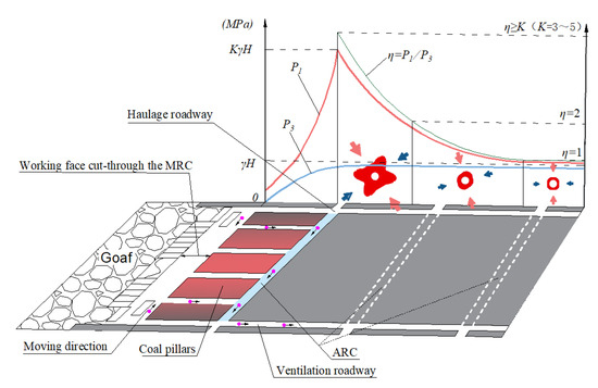
Figure 7.
Morphological characteristics of the plastic zone in the auxiliary retracement channel with different spacings.
If the protective coal pillars are narrow, the ARC is located in a high deviatoric stress environment, deflects the principal stress at a certain angle and produces a butterfly-shaped plastic zone in the ARC surrounding the rock. With an increase in the width of the protective coal pillars, the mining influence on the ARC gradually diminishes, which decreases the nonuniformity in the main stress distribution. The plastic zone in the ARC is reduced in range with weakened asymmetry as a result of an elliptical-shaped plastic zone. When the protective coal pillars are wide, the ARC is slightly influenced by mining, the principal stress distribution is uniform, and the plastic zone shape is circular.
4. Numerical Simulation Analysis
4.1. Numerical Simulation Model
According to the mechanical parameters of each coal and rock stratum in the Lijiahao 22-116 working face [29], combined with the site geological conditions, the FLAC3D 6.0 finite element software was used to establish a three-dimensional numerical model, as shown in Figure 8. The deformation and damage to the ARC are simulated after the working face has been cut through the MRC.
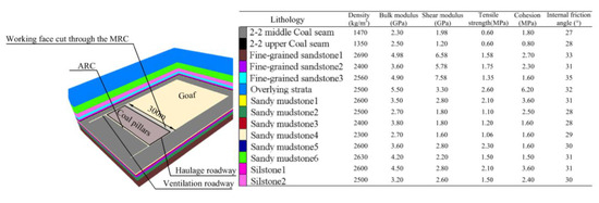
Figure 8.
Numerical simulation model and mechanical parameters of each coal and rock stratum.
The model adopts the Mohr–Coulomb damage criterion based on the elastic-plastic theory, with fixed constraints around and at the floor surface and a free boundary at the top surface. The overlying rock was 120 m from the surface, and 3MPa of stress was applied on the top surface to compensate for the self-weight stress of the overlying rock. The coal seam with its roof and floor cell size was 0.5 m. The ARC was a rectangular section (3 m high; 5 m wide). The model excavated the haulage roadway and ventilation roadway, excavated the MRC and ARC, and gradually excavated the coal seam until it cut through with the MRC.
4.2. Distribution of the Mining Stress Field in front of the Working Face
Working face mining disrupts the original rock stress equilibrium state and redistributes stresses. Due to the strong influence of mining, stress concentration occurs in the coal pillars in front of the working face. The stress field changes after the stress redistribution. The changes in P1 and P3 in the range of 0~70 m for the front coal pillars were tested to obtain the stress field distribution change law, as shown in Figure 9.
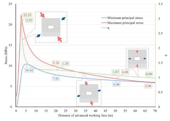
Figure 9.
Distribution of the 0~70 m mining stress field in front of the working face.
The original rock stress (γH) at the site without mining disturbance is 5 MPa. P1, in the coal pillars in front of the working face, sharply increases from less than γH to a peak of 22.35 MPa at 2.5 m, which is 4.47 times the original rock stress; then, it decreases to 2γH at a faster rate and slowly returns to γH when the stress magnitude moves further from the working face. P3 relatively quickly increases from 0 to a peak of 10.42 MPa at 5 m in front, slowly decreases to γH and, subsequently, stabilizes.
Based on the above analysis, the numerical simulation results for the stress field distribution in front of the working surface are consistent with the theoretical analysis. The stress concentration phenomenon caused by mining leads to a nonuniform distribution of P1 and P3, and forms a deviatoric stress environment. Moreover, while the stress is concentrated, the directions of P1 and P3 will simultaneously be deflected at a certain angle. Protective coal pillars with different widths will mean that the ARC is located under different degrees of deviatoric stress, and the roadway surrounding rock will be damaged in different forms.
4.3. Shape Characteristics of the Plastic Zone in the Surrounding Rock of the Auxiliary Retracement Channel in the Deviatoric Stress Environment
With the changes in the width of the protective coal pillars between the two retracement channels, the evolution characteristics of the shape of the plastic zone in the ARC surrounding rocks in different deviatoric stress environments are obtained after the working face has been cut through the MRC. With the increasing width of the protective coal pillars, the plastic zones in the ARC are butterfly shaped, elliptical and circular, as shown in Figure 10.
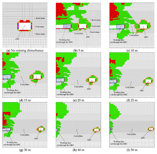
Figure 10.
Shape characteristics of the plastic zone in the auxiliary retracement channel with different protective coal pillar widths.
For example, Figure 10 shows that the surrounding rock plastic zone is uniformly distributed along the centerline of the rectangular roadway when the retracement channel is not influenced by mining. The plastic zone in the two sides and floor has a maximum depth of 0.5 m, while that of the roof is 1 m.
When the working face is cut through the MRC, the self-weight stress of the overlying rock is transferred to the protective coal pillars between the two retracement channels. When the protective coal pillars are narrow, the ARC is in a high deviatoric stress environment with stress concentration and deflection, which forms a butterfly-shaped plastic zone. Deflection of the butterfly-shaped plastic zone occurs. The deepest part of plasticity occurs above the roof, the plastic zone at the roof expands to the secondary side, and the plastic zone at the floor expands to the primary side (it is defined as the primary side near the working face, and the far side is the secondary side). Asymmetric, large deformation occurs in the ARC (Figure 10b–d). When the width of the protective coal pillars increases, the ARC is located far from the working face and the mining stress influence is reduced. The concentration degree, deflection angle, and uneven distribution of stresses are weakened, which gradually reduces the range of the plastic zone. As shown in Figure 10e–h, the plastic zone is concentrated in the corner of the rectangular roadway, and the deepest part is in the roof near the secondary side, which has an elliptical shape. When the width of the protective coal pillars continues to increase, the ARC is less influenced by mining, and the plastic zone form is similar to a circular shape, which is more uniformly distributed around the roadway (Figure 10i).
At the end of the mining period, the numerical simulation calculated the shape characteristics of the plastic zone in the ARC, which were consistent with the shape characteristics of the nonuniform stress field plastic zone derived from the theoretical calculations. With the nonuniform degree of distribution of P1 and P3 in the stress field where the roadway is located, the plastic zones in the surrounding rock are round, elliptical, and butterfly shaped. Because the numerically simulated roadway is a rectangular section and the redistributed stress field caused by mining is very complex, the size range of the numerically simulated plastic zone shape is slightly different from the shape characteristics calculated according to the theory. However, the shape characteristics of the plastic zone change law remain consistent.
5. Results and Discussion
5.1. Influence of the Plastic Zone Shape on the Stability of the Auxiliary Retracement Channel
Theoretical and numerical simulations verified that mining will cause stress concentrations in a certain range of the coal pillar in front of the working face and form a high deviatoric stress environment with a large difference between P1 and P3. The plastic zone in the ARC surrounding rock in a high deviatoric stress environment is butterfly shaped. When the ARC is far from the working face, the mining influence is weakened, and the plastic zone shape of the roadway becomes elliptical and circular.
The butterfly-shaped plastic zone is not uniformly distributed, easily making the ARC surrounding rock undergo serious asymmetric deformation, and is in an unstable state. In addition, influenced by the concentrated and deflection stress, the plastic zone with the butterfly shape expands, a large amount, above the roof. The plastic zone depth is beyond the effective range of the available anchor bolts and cables, which makes the support body fail, the roof sinking is large, and even the roof falls. The elliptical plastic zone is more uniformly distributed than the butterfly-shaped plastic zone, and the maximum depth is reduced. The anchor bolts and cables can provide effective support, and the ARC is relatively stable. The circular plastic zone is barely influenced by mining, the extent of the plastic zone is the smallest, and the surrounding rock has the best stability.
5.2. Method for Determining the Reasonable Spacing of Two Retracement Channels
At the end of the mining period, after the working face has been cut through the MRC, the self-weight stress of the overlying rock is mainly transferred to the protective coal pillar between the two retracement channels, so the spacing of the two retracement channels becomes critical to protect the stability of the ARC. Determining the reasonable spacing of the two retracement channels optimizes the channel layout under the premise of ARC stability, minimizes the size of the protective coal pillars, and improves the productivity of coal mining enterprises, while reducing the waste of coal resources.
The key to reasonable spacing is to ensure the stability of the surrounding rock in the ARC during the retracement of the equipment. Based on the above analysis, Figure 11 illustrates the ARC with different protective coal pillar widths in the stress environment, the plastic zone shape characteristics, and the surrounding rock stability state.
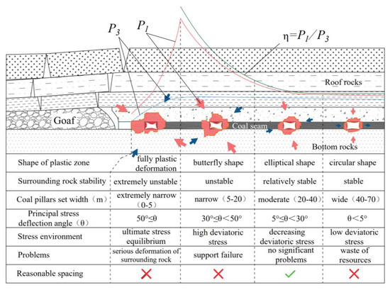
Figure 11.
Reasonable spacing determination method.
Mining makes P1 and P3 nonuniformly distributed in magnitude and direction in front of the working face, which results in ultimate stress equilibrium, high deviatoric stress, decreasing deviatoric stress, and low deviatoric stress environments. With an increase in the double retracement channel spacing, the ARC is in different stress environments during the end of the mining period, which produces different shape characteristics of the plastic zone.
The ARC is in the ultimate stress equilibrium environment when the coal pillars are set extremely narrow (0~5 m). Because of the stress field migration, the protective coal pillars have experienced the action of multiple stress fields, which have entirely undergone plastic deformation and lost their bearing capacity. The surrounding rock in the ARC is severely non-symmetrically deformed and extremely unstable. When narrow coal pillars (5~20 m) are set, the ARC is in a high deviatoric stress environment, the plastic zone has a butterfly shape, and the surrounding rock is asymmetrically deformed with poor stability and challenging support control. When moderate-width coal pillars (2~40 m) are set, the ARC is in the decreasing deviatoric stress environment. The shape of the plastic zone is elliptical and more uniformly distributed, which can control the stability of the surrounding rock through the support of anchor bolts and anchor cables. When wide coal pillars (40~70 m) are set, the ARC is less influenced by mining and is in a low deviatoric stress environment. The shape of the plastic zone is circular, which has stable surrounding rock, but the coal pillars cannot be recovered, and additional resources are wasted.
The width of the protective coal pillars that correspond to the different shape characteristics of the previously mentioned plastic zones is not an invariant quantity. In general, greater ground stress and weaker mechanical strength of the rock correspond to wider protective coal pillars and greater stability in the ARC.
The above analysis shows that the reasonable spacing of the two retracement channels is 20~40 m; however, this range is not invariant and can be adjusted according to actual environmental changes. The key to reasonable spacing is to ensure that the protective coal pillars are sufficiently wide to mean that the ARC is in a decreasing deviatoric stress environment, and the plastic zone should exhibit a stable elliptical shape.
5.3. Engineering Application Effect Analysis
Based on the above reasonable spacing determination method, the spacing of the pre-excavated double retracement channels for the 22-116 working face at the Lijiahao Mine is determined. Through the results from the numerical simulation analysis, when the protective coal pillar is wider than 20 m, the ARC is in the decreasing deviatoric stress environment, the plastic zone shape is elliptical, and the plastic zone size effect on the surrounding rock stability is considered. The spacing between the two retracement channels, set to 25 m, is determined during the application of the actual project.
To obtain the surrounding rock deformation in the ARC at the end of the mining period, 17 surface displacement monitoring stations were uniformly arranged in the ARC. The displacement between the floor and roof and between the two sides are shown in Figure 12. With a 25 m protective coal pillar set, the surface displacement of the ARC is small overall: the average is 22.9 mm between the roof and floor and 17.1 mm between the two sides. The deformation and damage in the surrounding rock in the ARC are not significant, with a small amount of sinking in the roof and an insignificant coal wall spalling phenomenon, which does not affect the normal use of the ARC.
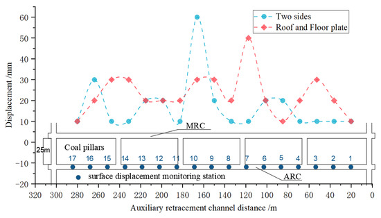
Figure 12.
Surface displacement changes at 17 monitoring points in the auxiliary retracement channel.
6. Conclusions
(1) The deviatoric stress environment formed by the nonuniform distribution of the maximum principal stress and minimum principal stress caused by mining is revealed, which reflects the formation of ultimate stress equilibrium, high deviatoric stress, decreasing deviatoric stress, and low deviatoric stress environments, away from the front of the working face.
The relationship between the shape characteristics of the plastic zone in the auxiliary retracement channel surrounding rock and the channel stability is revealed. With an increase in the width of the protective coal pillars, the shape of the surrounding rock plastic zones experience full deformation, butterfly shaped, elliptical, and circular, which indicates extremely unstable, unstable, relatively stable, and stable channels, respectively.
(2) The mechanical essence of the surrounding rock in the auxiliary retracement channel forming the plastic zones with different shape characteristics is that the channel is experiencing different degrees of deviatoric stress. When the auxiliary retracement channel is in the high deviatoric stress environment, the plastic zone in the surrounding rock is butterfly shaped; in the decreasing deviatoric stress environment, the plastic zone is elliptical; and in the low deviatoric stress environment, the plastic zone is circular.
(3) A method to determine the reasonable spacing of the pre-excavated double retracement channels is proposed. The necessary condition for reasonable spacing is to arrange the auxiliary retracement channel in the decreasing deviatoric stress environment, which can effectively control the stabilization of the surrounding rock and avoid a waste of resources caused by being unable to recover numerous coal pillars. The retracement efficiency is effectively improved through engineering practice verification, setting the pre-excavation spacing for the two retracement channels at the Lijiahao Mine 22-116 working face to 25 m, placing the auxiliary retracement channel in the deviatoric stress environment, which ensures the surrounding rock stability at the end of the mining period, and the safe and efficient completion of the equipment retracement.
Author Contributions
Conceptualization, X.G. (Xu Gao), H.Z. and X.G. (Xiaofei Guo); Methodology, H.Z.; Software, K.Y. and Y.H.; Formal analysis, C.L.; Investigation, Y.H.; Resources, H.Z.; Data curation, C.L. and K.Y.; Writing—original draft, X.G. (Xu Gao) and C.L.; Supervision, X.G. (Xiaofei Guo); Project administration, X.G. (Xu Gao) and X.G. (Xiaofei Guo); Funding acquisition, X.G. (Xu Gao). All authors have read and agreed to the published version of the manuscript.
Funding
China Academy of Railway Sciences Youth Fund Project: 2023YJ187; China State Railway Group Co., Ltd. Focused Fund: N2021G002; National Natural Science Foundation of China High Speed Rail Joint Fund: U2268217.
Institutional Review Board Statement
Not applicable.
Informed Consent Statement
Not applicable.
Data Availability Statement
The data can be provided if necessary.
Conflicts of Interest
The authors declare that they have no conflict of interest.
References
- Ju, Y.; Wang, Y.; Su, C.; Zhang, D.; Ren, Z. Numerical analysis of the dynamic evolution of mining-induced stresses and fractures in multilayered rock strata using continuum-based discrete element methods. Int. J. Rock Mech. Min. Sci. 2019, 113, 191–210. [Google Scholar] [CrossRef]
- Fei, L.; Jiang, Z. Research on Deformation Mechanism of Retracement Channel during Fully Mechanized Caving Mining in Superhigh Seam. Adv. Civ. Eng. 2018, 2018, 1368965. [Google Scholar] [CrossRef]
- Zhang, F.; Wang, X.; Bai, J.; Wu, W.; Wu, B.; Wang, G. Fixed-length roof cutting with vertical hydraulic fracture based on the stress shadow effect: A case study. Int. J. Min. Sci. Technol. 2022, 32, 295–308. [Google Scholar] [CrossRef]
- Malashkevych, D.; Petlovanyi, M.; Sai, K.; Zubko, S. Research into the coal quality with a new selective mining technology of the waste rock accumulation in the mined-out area. Min. Miner. Depos. 2022, 16, 103–114. [Google Scholar] [CrossRef]
- Vu, T.T. Solutions to prevent face spall and roof falling in fully mechanized longwall at underground mines, Vietnam. Min. Miner. Depos. 2022, 16, 127–134. [Google Scholar] [CrossRef]
- Lou, J.; Gao, F.; Yang, J.; Ren, Y.; Li, J.; Wang, X.; Yang, L. Characteristics of evolution of mining-induced stress field in the longwall panel: Insights from physical modeling. Int. J. Coal Sci. Technol. 2021, 8, 938–955. [Google Scholar] [CrossRef]
- Zhao, H.; Cheng, H.; Ji, D.; Wang, T.; Wang, Y.; Jiang, C. Study of the mechanism and evolution law of unsymmetrical failure of the mining roadway in close distance coal seam. Int. J. Min. Sci. Technol. 2021, 50, 1029–1040+1050. [Google Scholar] [CrossRef]
- Li, W.; Tu, S.; Tu, H.; Li, Y.; Liu, X.; Miao, K. Failure characteristics and control techniques for mining roadway affected by stress accumulation of residual pillars in contiguous coal seams. Eng. Fail. Anal. 2022, 141, 106646. [Google Scholar] [CrossRef]
- Wu, R.; Zhang, P.; Kulatilake, P.H.; Luo, H.; He, Q. Stress and deformation analysis of gob-side pre-backfill driving procedure of longwall mining: A case study. Int. J. Coal Sci. Technol. 2021, 8, 1351–1370. [Google Scholar] [CrossRef]
- Suchowerska, A.; Merifield, R.; Carter, J. Vertical stress changes in multi-seam mining under supercritical longwall panels. Int. J. Rock Mech. Min. Sci. 2013, 61, 306–320. [Google Scholar] [CrossRef]
- Babets, D.; Sdvyzhkova, O.; Hapieiev, S.; Shashenko, O.; Vasyl, V. Multifactorial analysis of a gateroad stability at goaf interface during longwall coal mining—A case study. Min. Miner. Depos. 2023, 17, 9–19. [Google Scholar] [CrossRef]
- Zhao, Z.Q.; Ma, N.J.; Liu, H.; Guo, X.F. A butterfly failure theory of rock mass around roadway and its application prospect. J. China Univ. Min. Technol. 2018, 47, 969–978. [Google Scholar] [CrossRef]
- Guo, X.; Ma, N.; Zhao, X.; Zhao, Z.; Li, Y. General shapes and criterion for surrounding rock mass plastic zone of round roadway. J. China Coal Soc. 2016, 41, 1871–1877. [Google Scholar] [CrossRef]
- Ma, N.; Zhao, X.; Zhao, Z.; Li, J.; Guo, X. Stability analysis and control technology of mine roadway roof in deep mining. J. China Coal Soc. 2015, 40, 2287–2295. [Google Scholar] [CrossRef]
- Smoliński, A.; Malashkevych, D.; Petlovanyi, M.; Rysbekov, K.; Lozynskyi, V.; Sai, K. Research into impact of leaving waste rocks in the mined-out space on the geomechanical state of the rock mass surrounding the longwall face. Energies 2022, 15, 9522. [Google Scholar] [CrossRef]
- Wang, B.; Dang, F.; Chao, W.; Miao, Y.; Li, J.; Chen, F. Surrounding rock deformation and stress evolution in pre-driven longwall recovery rooms at the end of mining stage. Int. J. Coal Sci. Technol. 2019, 6, 536–546. [Google Scholar] [CrossRef]
- He, Y.; Song, Y.; Shi, Z.; Li, J.; Chen, K.; Li, Z. Study on failure mechanism of withdrawal channel’s surrounding rock during last mining period. China Saf. Sci. J. 2022, 32, 158. [Google Scholar] [CrossRef]
- Li, C.; Guo, X.; Huo, T.; Liu, R. Coal pillar design of pre-excavated double equipment withdrawal channel and its surrounding rock stability control. J. Huazhong Univ. Sci. Technol. 2021, 49, 1–7. [Google Scholar] [CrossRef]
- LV, H.-W. The mechanism of stability of predriven rooms and the practical techniques. J. China Coal Soc. 2014, 39, 50–56. [Google Scholar] [CrossRef]
- He, F.; Lv, K.; Li, X.; Qin, B.; Li, L. Failure mechanism and control of lower retracement channel in close-distance double-thick coal seams. Shock. Vib. 2021, 2021, 1–19. [Google Scholar] [CrossRef]
- Guo, Y.; Yu, H. Research and application of roof cutting and pressure release technology of retracement roadway in large height mining working face. Geotech. Geol. Eng. 2021, 39, 1289–1298. [Google Scholar] [CrossRef]
- Gu, S.; Wang, B.; Huang, R.; Miao, Y. Method for determining the load on and width of coal pillar at the recovery room end of fully-mechanized longwall mining. J. China Univ. Min. Technol. 2015, 44, 990–995. [Google Scholar] [CrossRef]
- Zhao, Z. Study on Mechanism and Control Method of Deformation and Failure of Surrounding Rock in Large Deformation Mining Roadway; China University of Mining and Technology: Beijing, China, 2014; pp. 26–32. [Google Scholar]
- Guo, X.; Zhao, Z.; Gao, X.; Wu, X.; Ma, N. Analytical solutions for characteristic radii of circular roadway surrounding rock plastic zone and their application. Int. J. Min. Sci. Technol. 2019, 29, 263–272. [Google Scholar] [CrossRef]
- Qian, M.; Shi, P.; Xu, J. Mining Pressure and Strata Control; China University of Mining and Technology Press: Xuzhou, China, 2010; pp. 98–101. [Google Scholar]
- Han, Y.; Wang, Z.; Tang, Y. Principal stress rotation in longwall top-coal caving face adjacent to the gob. J. China Coal Soc. 2020, 45 (Suppl. S1), 12–22. [Google Scholar] [CrossRef]
- Wang, J.C.; Wang, Z.H.; Yang, S.L. Stress analysis of longwall top-coal caving face adjacent to the gob. Int. J. Min. Reclam. Environ. 2020, 34, 476–497. [Google Scholar] [CrossRef]
- Tao, Z.; Song, Z.; He, M.; Meng, Z.; Pang, S. Principles of the roof cut short-arm beam mining method (110 method) and its mining-induced stress distribution. Int. J. Min. Sci. Technol. 2018, 28, 391–396. [Google Scholar] [CrossRef]
- LI, F. Research on the Technology of Upper and Lower Simultaneous Mining in Shallow Thin Bedrock Coal Seam; China University of Mining and Technology: Beijing, China, 2013. [Google Scholar]
Disclaimer/Publisher’s Note: The statements, opinions and data contained in all publications are solely those of the individual author(s) and contributor(s) and not of MDPI and/or the editor(s). MDPI and/or the editor(s) disclaim responsibility for any injury to people or property resulting from any ideas, methods, instructions or products referred to in the content. |
© 2023 by the authors. Licensee MDPI, Basel, Switzerland. This article is an open access article distributed under the terms and conditions of the Creative Commons Attribution (CC BY) license (https://creativecommons.org/licenses/by/4.0/).