1. Introduction
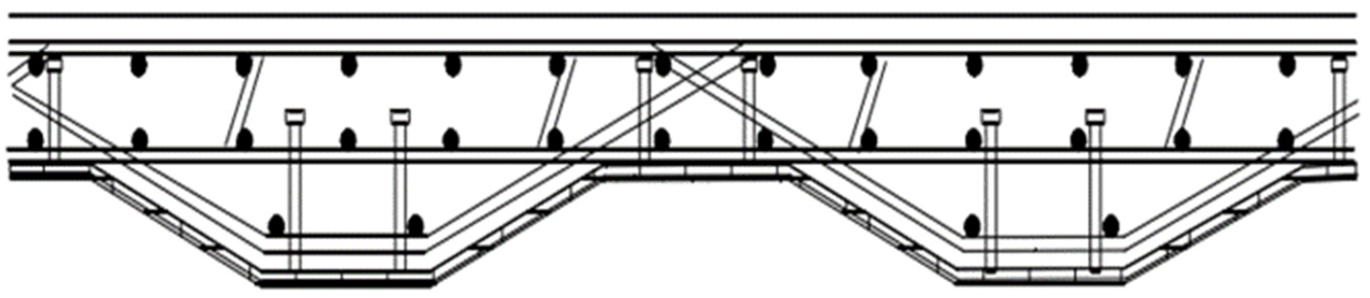
A corrugated steel–concrete deck slab, which is based on the traditional steel–concrete deck slab, converts the flat bottom steel plate into a corrugated steel plate and consists of steel fiber concrete, load-bearing tendons, steel wire mesh, and other components. The corrugated steel–concrete deck is also known as a four-steel deck. The wave-fold steel–concrete combination bridge deck can improve the traditional steel–concrete combination bridge deck’s shear performance and bearing capacity, stiffness on the short board, and provide a strong boost to bridge deck structure innovation and development.
Shear keys have made a great contribution to the development of steel–concrete composite structures by transferring shear forces from the longitudinal direction in the structure, resisting the slippage of concrete and steel plates, and lifting steel plates [
1]. With the development of the bridge, shear connection keys have also been developed accordingly, and the more widely used shear keys in engineering can be divided into rigid shear keys and flexible shear keys. Among them, the most common forms of rigid shear keys are steel sections and PBL open steel plates. Flexible shear keys are commonly available in the form of shear studs and steel shear keys. A schematic diagram of the corrugated steel–concrete composite deck slab is shown in
Figure 1 [
2].
Compared to ordinary reinforced concrete decks and flat-bottomed steel–concrete composite decks, the advantages of corrugated steel–concrete decks are the following.
- (1)
By using a combination of corrugated steel plates and concrete, the structural stiffness and ultimate flexural load capacity of the bridge deck are increased while reducing the self-weight of the deck structure.
- (2)
The lower surface of the bridge deck slab can be used directly as a concrete formwork during construction by using the form of corrugated steel plates, which improves the convenience of construction while saving construction costs.
- (3)
In the maintenance of bridges, corrugated steel plates can be used as fall protection plates, which is undoubtedly very beneficial for bridge operations [
3].
While constructing the composite deck, connecting reinforcement bars and hoop bars creates a reinforcement network that enhances the overall deck stiffness. The reinforcement skeleton is welded to the bending steel plate, providing added torsional resistance to the structure. The shear studs, welded to the bending steel plates as shear connection keys, contribute to the small size and strong shear resistance of the structure. This design feature provides effective anti-slip and anti-peel characteristics in the bending steel–concrete deck slab [
4,
5,
6].
As a new type of steel–concrete composite structure, the shear connection member is a vital component in steel–concrete composite structures used in highway bridges and offshore structures. It facilitates the full utilization of the unique properties of both materials and ensures their coordination and synchronization of the two deformations [
7]. The pinned shear key, with its excellent shear resistance, straightforward construction process, and easy-to-produce materials, has been welcomed by the engineering community. It is located at the interface between the concrete and the bending steel plate, bending that is mainly caused by the longitudinal shear force of the bridge deck, in the role of structural shear, and it also plays a role in limiting the relative slip of the interface between the bending steel plate and the concrete [
8,
9,
10]. It can be said that the excellent shear performance of the shear connection key determines the working performance of the combined deck. Therefore, it is particularly important to study the shear performance and slip of shear connection keys.
In 2008, Jeong Y. J. conducted a study on predicting the partial-interactive behavior of steel–concrete composite slabs using a simplified model. The research involved performing nonlinear partial-interaction analyses to address the partial-interactive problem. Parameters like interaction level and shear span ratios were varied. A simplified model describing the partially interactive system’s structural performance was developed from collected data and validated through tests [
11]. In 2009, Jeong Y. J., Kim H. Y., and Koo H. B. studied shear connection bonds using push-out and beam tests. They suggested using test data with ample shear span length for accurately determining the longitudinal shear resistance of steel–concrete composite bridge slabs subjected to surface loads [
12]. In 2010, Ahn J. H., Sim C., Jeong Y. J., and SH Kim tested corrugated steel–concrete composite deck members subjected to symmetrical loading. The study analyzed the force performance under these conditions and offered a theoretical explanation for the normal pressure on the contact surface concerning the structural longitudinal shear performance [
13,
14]. In 2011, Kang S. K. and Lee D. H. focused on the flexural behavior of non-prestressed and prestressed composite beams with corrugated webs. The proposed flexural behavior model accurately estimated behavior before and after concrete addition. Horizontal shear strengths were evaluated, considering shear bond and concrete strength [
15]. In 2012, K.M.A. Sohel et al. predicted the ultimate strength of steel–concrete–steel sandwich beams with various shear connectors. Design recommendations were made based on minimum connector spacing to prevent shear cracking and local buckling [
16]. In 2013, Marko Pavlović et al. proposed a shear resistance reduction factor for bolted shear connectors after investigating shear connector height effects [
17]. In 2014, George Vasdravellis et al. explored shear strength and moment–shear interaction in steel–concrete composite beams. Thickness and shear connection were identified as key factors affecting shear capacity [
18]. In 2017, a static analysis by Hoshina H, Fujiyama C. using a full-scale model showed that the stress distribution in the studs themselves and the damaged state of the con-crete around them depend on their locations. Design equation coefficients for studs with heads as shear connectors for steel-concrete composite decks are proposed, taking into account the effects of normal forces and the position of each stud [
19]. In 2018, Gholamhoseini presented the results of tests on continuous composite concrete slabs with trapezoidal steel decking. The study evaluated longitudinal shear failure, deflection, and redistribution of bending moment, proposing a finite element model [
20]. In 2021, Bruno J., Firas T., and Emmanuel F. studied adhesive bonding connections, showing that their behavior resembles that of mechanical connectors. The study highlighted their structural ductility and potential advantages [
21]. Hosseini S. M. et al. validated a 3D numerical model using experimental tests and proposed shear stress and ductility criteria for an innovative shear connector. The load-carrying capacity of composite beams using bolted shear connectors was influenced by various factors [
22]. Avudaiappan et al. experimented with bolted shear connectors on composite deck slabs, finding that dovetailed profiled composite slabs exhibited higher resistance [
23].
Nowadays, the traffic is more developed, and the requirements of the bridge deck plate, which is one of the main components of the bridge deck system, are becoming increasingly high [
24]. The traditional reinforced concrete bridge deck plate is gradually unable to meet the demand of traffic volume due to its own limitations of self-weight and poor ductility, crack resistance, and shear resistance [
2]. At present, there is less research on the form of the bridge deck slab, which is a combination of undulating steel and concrete. Therefore, this paper investigates the shear performance and slip of the new composite bridge deck structure, which uses the corrugated steel plate as the base plate, and analyzes the shear performance and slip of the composite bridge deck based on the structure of pegs and PBL perforated steel plate as the shear connection key. The shear performance of the composite deck is analyzed based on the structure of shear connection keys such as pegs and PBL perforated steel plates. The advantages of the composite decks in terms of stiffness, self-weight, load-bearing capacity, shear resistance, slip resistance, etc., are discussed to provide a theoretical reference for practical engineering applications.
2. Finite Element Simulation of the Shear Resistance of Shear Studs in Combined Decks
ABAQUS software was used to model a local launch experiment for a corrugated steel–concrete composite deck slab in an engineering example to investigate the shear resistance of the shear connection keys of the shear studs in the corrugated steel–concrete composite deck slab [
25,
26].
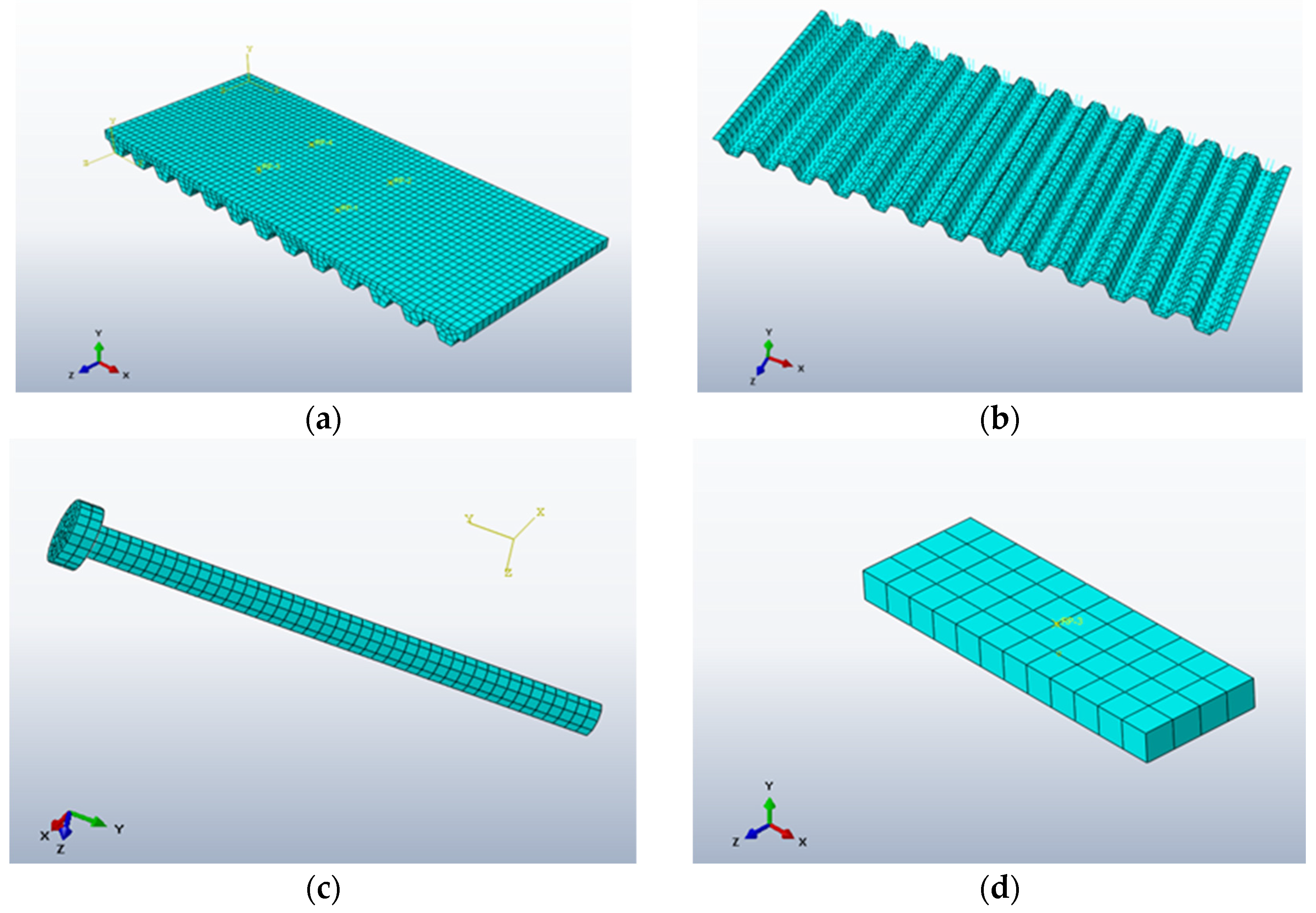
In the finite element software (the ABAQUS 2020), when the thickness direction dimension of the member is much smaller than the other two dimensions and the stress in the thickness direction can be neglected, it is appropriate to use the unit type of shell cell [
27]. In this project example, the thickness of the bending steel plate, t, is only 6 mm, which is a thin-walled member, so the unit type used for the bending steel plate is the shell unit. For the shell unit, the general shell unit allows the thickness of the shell to change with the deformation of the unit, while other shell units assume that only limited rotation of the unit nodes can occur. The quadrilateral shell cell (except S4) and the triangular shell cell S3/S3R use reduced integration, so the quadrilateral shell cell of S4R is more suitable for the bending steel plate with a small thickness and prone to the shear locking phenomenon.
For the concrete with a more complex force state, the solid unit, which can simulate the most types of components, is used in this paper. Among the solid units, the C3D8R unit with reduced integration, i.e., a six-sided unit with eight nodes, is selected, which is more accurate and less prone to shear locking.
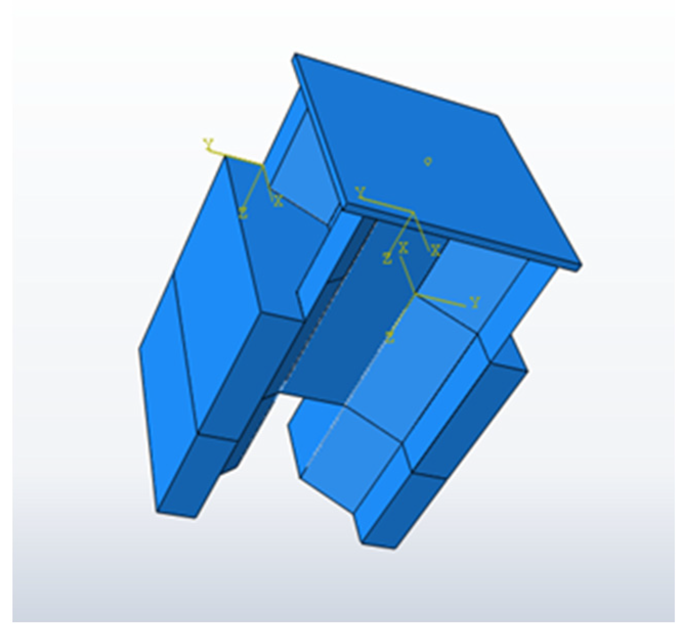
The establishment of the finite element model is shown in
Figure 2,
Figure 3 and
Figure 4, and the material parameters of each component are shown in
Table 1.
In order to make the meshing more reasonable and accurate, the meshing technique and the meshing algorithm used in this paper are free meshing and the advanced algorithm, respectively. The mesh size of the concrete is 50 mm, the mesh size of the corrugated steel plate is 75 mm, the mesh size of the reinforcement and shear connection keys is 50 mm, and the mesh size of the loading mat is 100 mm. The mesh model of the composite deck is shown in
Figure 4 below:
In the process of finite element modeling of the experiment, the concrete is of type C50 and the reinforcement is structural reinforcement. The number of pinned shear keys is set to two groups on each part of the corrugated steel plate and welded to the corrugated steel plate, the connection between the steel mat and I-beam, corrugated steel plate and I-beam are set to Tie, and the rest of the specific parameters are shown in
Table 1.
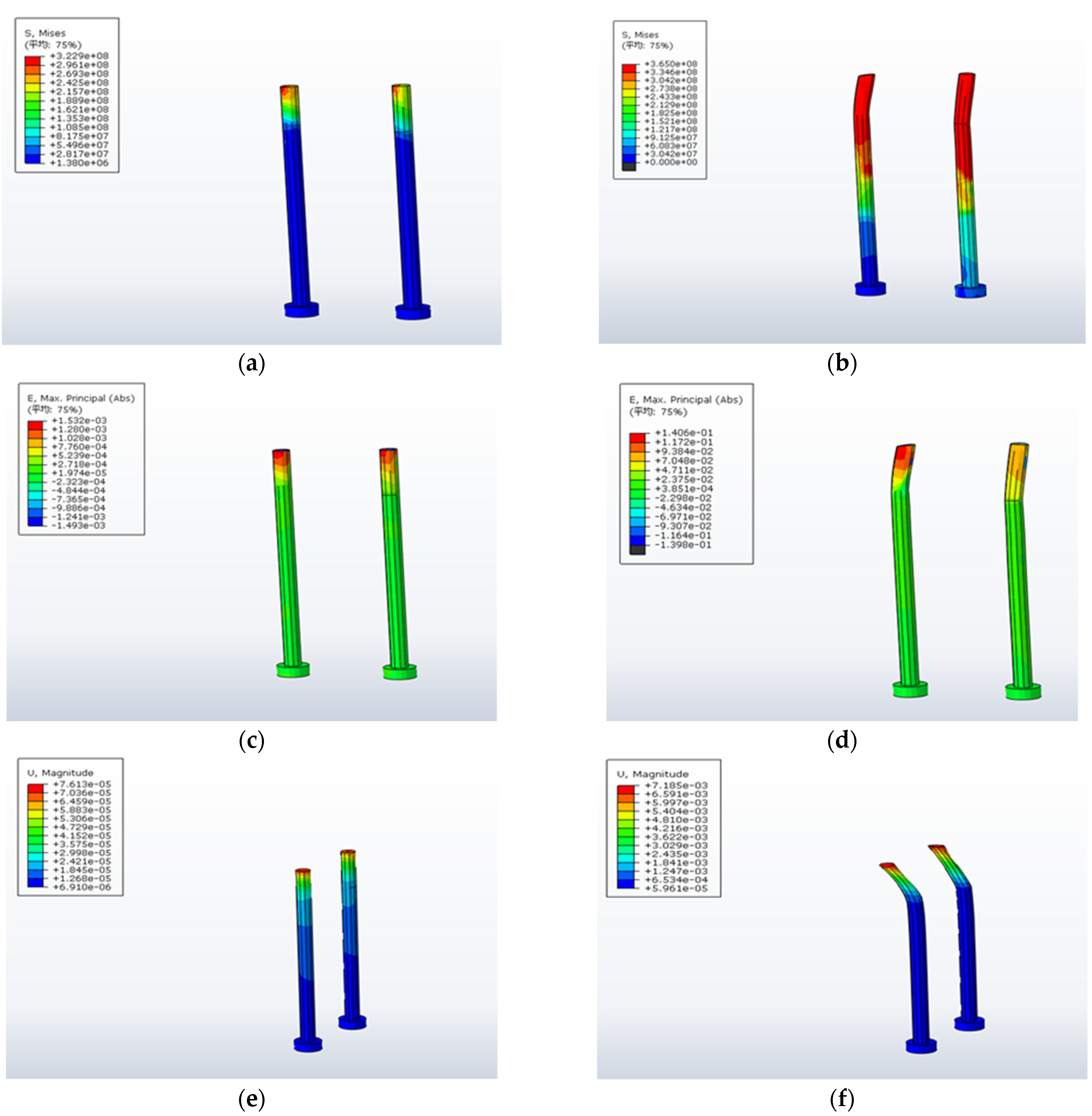
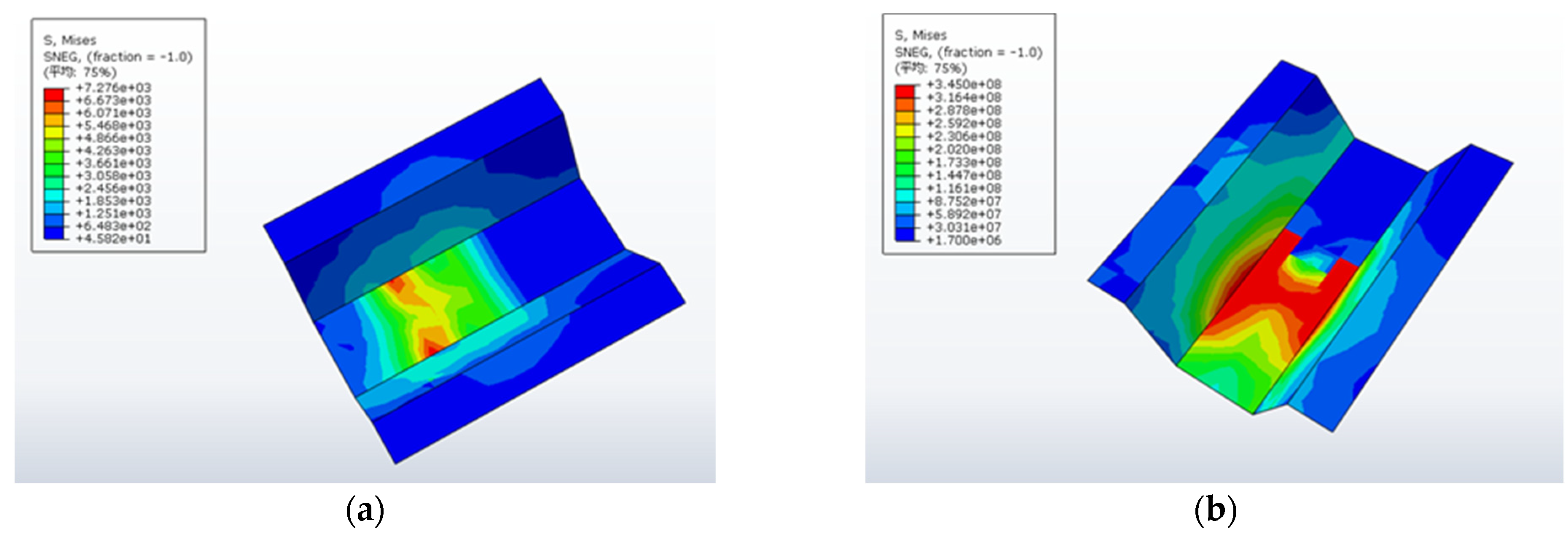
During the experimental loading process, the end of the concrete portion was fixedly constrained, and a displacement load of 0.12 mm/s was applied to the top steel plate. At this time, relative displacement occurred between the corrugated steel plate and the concrete, the pinned shear key started to work and transfer the shear force, and the loading continued until the damage. The stress, strain, and displacement clouds for the component damage are shown in
Figure 5 and
Figure 6 (The “
平均” in the figure represents the average).
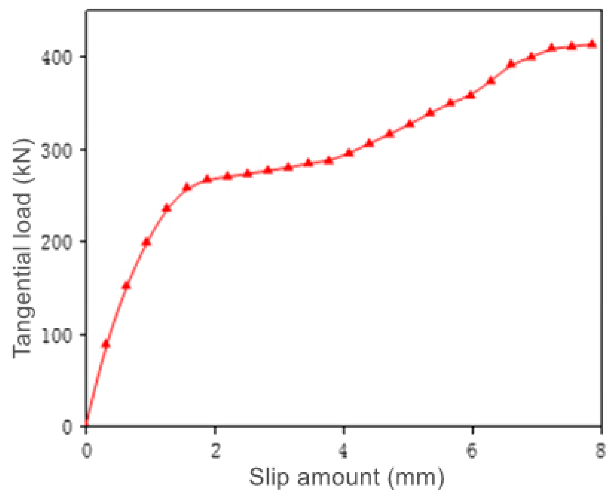
As can be seen from the above finite element simulation clouds, the member was damaged when the lower part of the shear stud bar reached a yield strength of 354 MPa and the bending steel plate locally reached a yield strength of 345 MPa, and the bottom of the concrete near the deformation direction of the shear stud was damaged by the ultimate compressive strain. The load slip curves and ultimate shear capacities of the two sets of pinned members are shown in
Figure 7 and
Table 2.
From the above load slip curve trend and the shear load capacity of the shear studs, the force process of the shear stud shear connection key in a corrugated steel–concrete composite deck slab carrying shear loads can be summarized in the following stages:
- (1)
Stage 1: when the tangential load is less than 258.4 kN with the continuous application of a vertical shear load, the structural force state of the corrugated steel–concrete composite deck is relatively stable, and the growth rate of slip is relatively slow. At this stage, the corrugated steel plate is not involved in the force, the deformation between the corrugated steel plate and the concrete is well coordinated, and there is no obvious peeling phenomenon. The longitudinal relative slip between the two at this stage is only 1.57 mm.
- (2)
Stage 2: when the tangential external load applied exceeds 258.4 kN but is less than 287.2 kN, the relative slip between the corrugated steel plate and the concrete begins to increase dramatically at this stage, and the rate of increase is much faster than the rate of increase of the external load. At this stage, the phenomenon of peeling between the corrugated steel plate and the concrete starts to occur, and the corrugated steel plate starts to participate in the force. At the end of this stage, the longitudinal relative slip between the two reached 3.77 mm, an increase of 140% compared to the end of the previous stage.
- (3)
Stage 3: as the tangential external load exceeds 287.2 kN and continues to increase, the growth rate of the relative slip between the corrugated steel sheet and the concrete shows signs of slowing down compared to Stage 2, but is still faster than the rate of load increase and is in a state of rapid increase. During this stage, the stress on the bending steel increases, and the transverse peeling between it and the concrete becomes more and more obvious. From a stable force, the component as a whole gradually tends to become unstable.
- (4)
Stage 4: when the tangential external load reaches about 410 kN, the whole element already shows a state of damage. At this point, the increase in external load becomes very small, while the slip between the corrugated steel plate and the concrete continues to increase rapidly. Eventually, when the external load reaches 413.4 kN, the pins are damaged by shear as they reach their ultimate strength, and the whole member loses its load-bearing capacity and may be damaged as a result. As can be seen from
Figure 6b, the concrete around the shear studs is crushed in the direction of tensile deformation when the composite deck member is damaged. The ultimate load carried by the whole combined deck element reached 413.4 kN.
3. Influence of the Structural Parameters of the Shear Stud on Its Shear Resistance
Like other members, the shear connection of shear studs has structural parameters, such as the length of the shear stud bar
and the diameter of the shear studs
As these parameters change, the shear resistance of the shear studs is affected to a certain extent, thus influencing the shear resistance of the overall composite deck structure [
28,
29]. Therefore, in this section, the effect of the height of the nail rod of the shear key on the shear capacity of the nails is investigated by studying the height-to-diameter ratio of the nails at
, based on the experimental finite element modeling of the nails introduced in the previous section [
10,
30,
31,
32]. The structural and specific material parameters of the shear studs are shown in
Figure 8 and
Table 3.
To investigate the effect of the height-to-diameter ratio of the shear connection key on the shear load capacity and shear stiffness of the shear studs themselves, three of the most commonly used shear studs, Φ16, Φ19, and Φ22, were prepared, and the shear stud heights
were divided into four different groups of 160 mm, 180 mm, 200 mm, and 230 mm. The two sets of parameters were matched to each other to form three sets of twelve symmetrical loading groups with different height-to-diameter ratios, each with four shear studs, numbered Ⅰ and Ⅱ on each side of the symmetry. There were two shear studs under each number. The shear stud arrangement is shown in
Figure 9 below, and the groups are shown in
Table 4.
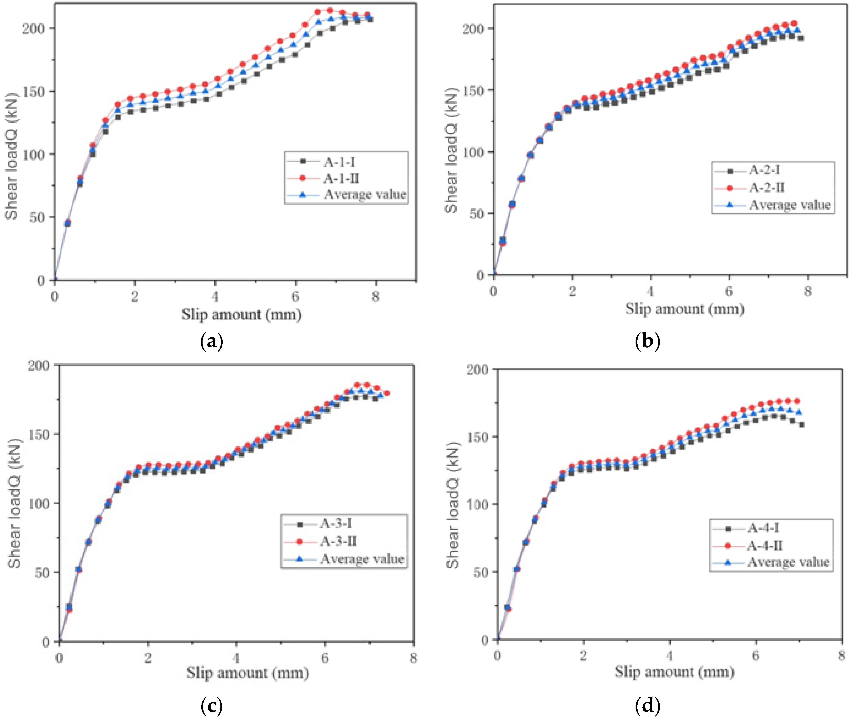
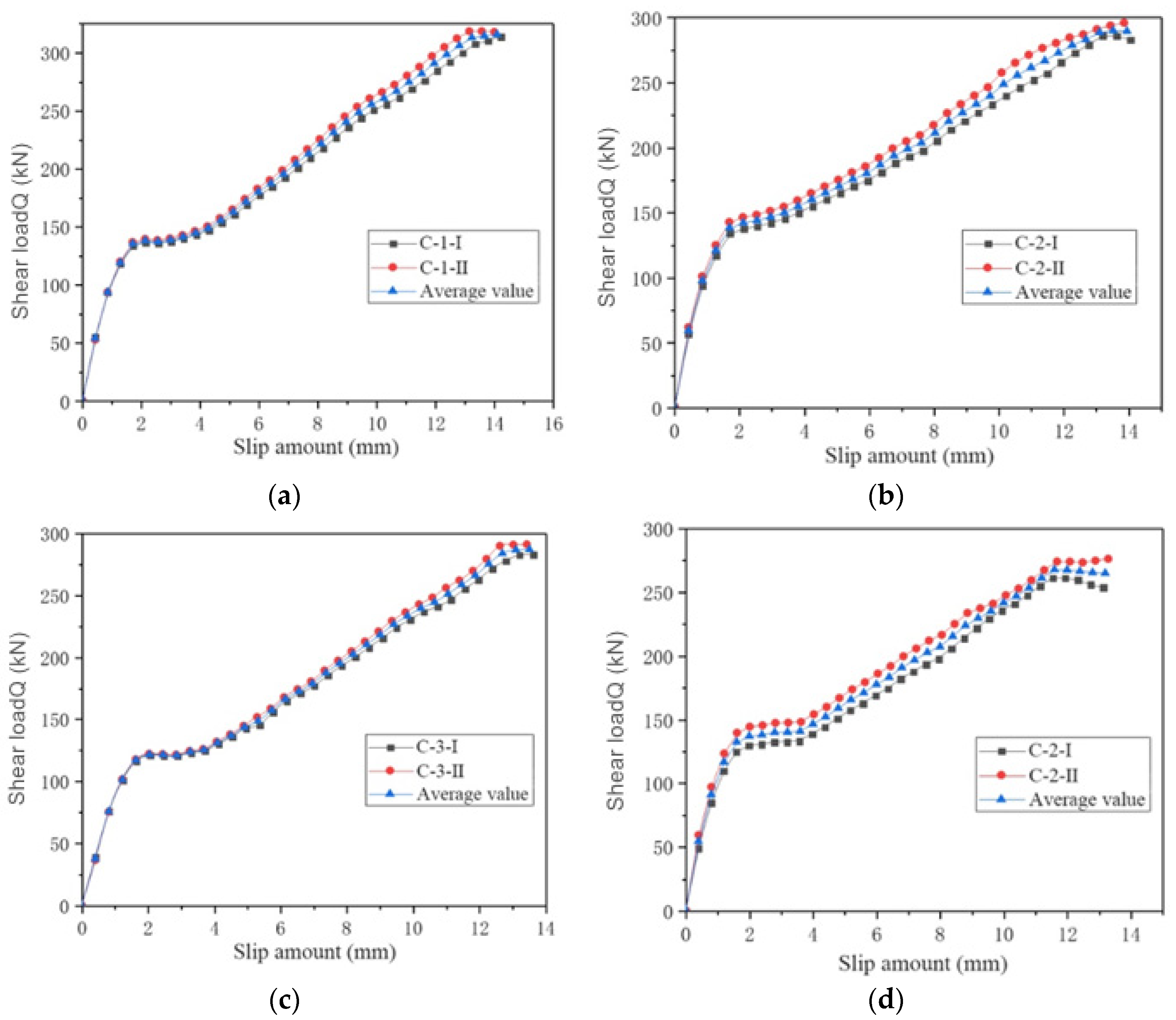
Under identical conditions, tangential loading finite element simulations are carried out for each of the above groups until the member is loaded to failure. The data were recorded and collated for analysis, and the finite element simulation results for each group are shown in
Figure 10,
Figure 11 and
Figure 12.
The load slip data obtained in the roll-out test model simulations for each of the above groups of shear stud shear keys were averaged and divided by two to obtain the shear performance index of individual shear studs with different height-to-diameter ratios and collated as shown in
Table 5.
With the increase in the height-to-diameter ratio of the shear connection key of the shear stud , the shear load capacity also increases accordingly. For group A of = 16 mm, the shear load capacity and shear stiffness of the pins with a height-to-diameter ratio of 14.4, 12.5, and 11.3 are 23%, 17%, and 6% higher than those with a height-to-diameter ratio of 10.0, respectively; for group B of = 19 mm, the shear load capacity and shear stiffness of pins with a height-to-diameter ratio of 12.1, 10.5, and 9.5 are 14%, 11%, and 5% higher than those with a height-to-diameter ratio of 8.4, respectively; for group C of = 22 mm, the shear load capacity and shear stiffness for height-to-diameter ratios of 10.4, 9.1, and 8.2 are 6%, 3%, and 2% higher than those for a height-to-diameter ratio of 7.3, respectively.
The height-to-diameter ratio of the spigot is an important factor influencing the shear resistance of the spigot. The influence of the height-to-diameter ratio is reflected in the fact that the ultimate shear capacity and shear stiffness of the spigot are generally increased with an increase in the height-to-diameter ratio. When the diameter of the shear stud is 16 mm or 19 mm, the shear bearing capacity increases significantly with the increase in the height-to-diameter ratio; when the diameter of the shear stud is 22 mm, the increase in the height-to-diameter ratio can also lead to an increase in the shear bearing capacity of the shear stud, but the increase is smaller. Overall, in practical engineering applications, taking into account the space occupied by the shear studs, the height restriction, and the cost, it is advisable to control the height-to-diameter ratio of the shear studs to around 9–12. The calculated and simulated values for groups B and C are close to each other, while the difference between the two values for group A is larger. is between 0.52 and 0.91. The height of the shear studs, , was not taken into account, resulting in the shear bearing capacity of the shear studs being generally less than the actual bearing capacity of the shear studs.
4. Finite Element Modeling of a Corrugated Steel–Concrete Composite Deck Slab Based on PBL and Pinned Shear Keys
To investigate the advantages of the new type of shear connection key, the PBL perforated steel plate, and the most widely used pinned shear connection key in terms of their respective force performance, this section uses the finite element software ABAQUS to model the PBL perforated steel plate shear key based on a local model of a bridge corrugated steel–concrete composite deck slab, in which, the PBL steel plate is made of Q235 steel, the corrugated steel plate is made of Q345c type, the concrete is made of C50 type, the reinforcement is structural reinforcement, and the mesh subdivision of the PBL open-hole steel plate model is carried out under the premise of considering the study on the shear bond force performance. The specific models are shown in
Figure 13 and
Figure 14, and the parameters are shown in
Table 6 and
Table 7.
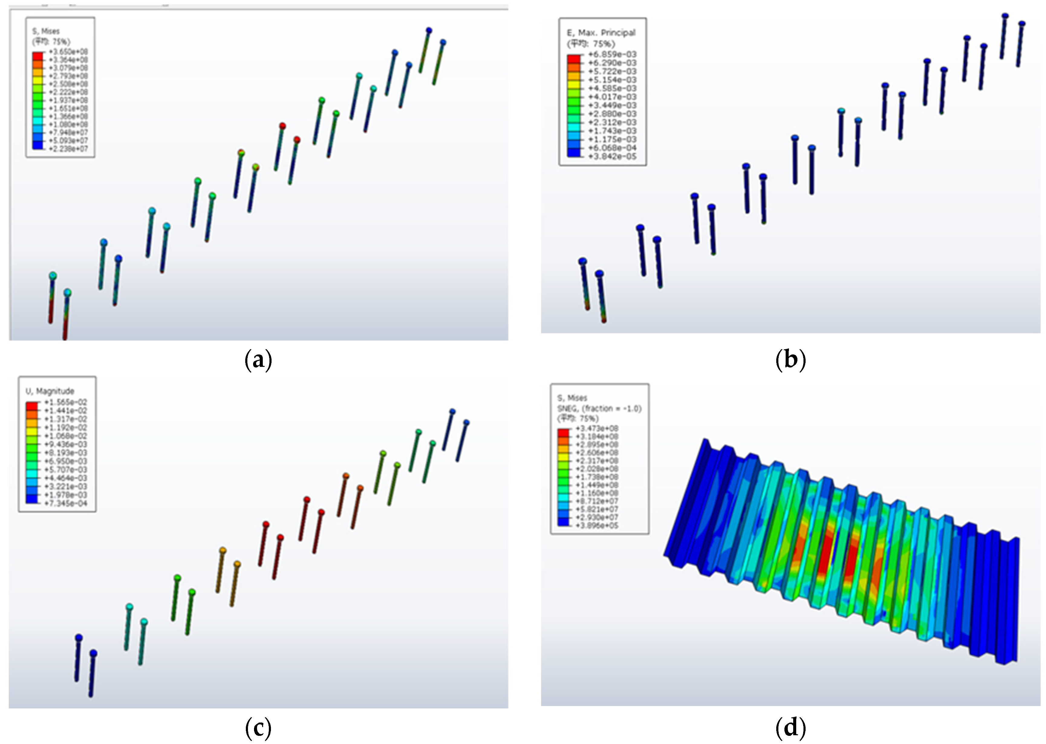
The undulating steel–concrete composite deck slab with PBL open-ended steel plate shear connectors and the composite deck slab with shear stud connectors were loaded under the external load P until the top concrete was crushed. The stress, strain, and displacement finite element clouds for the PBL perforated steel and shear stud-based composite deck slabs are shown in
Figure 15 and
Figure 16, respectively (The “
平均” in the figure represents the average).
As can be seen from the above diagram, the final stressing of the combined deck slab based on the PBL open-hole steel plate shear connection key under vertical load P is as follows: the PBL shear connection key and the corrugated steel plate in the span reach yield strength, and the transverse penetration reinforcement in the span wrapped by the concrete tenon also reaches yield strength. Eventually, the upper concrete reaches its ultimate compressive strength and is crushed, and the member is withdrawn from service and destroyed. In contrast, the stresses on the composite deck based on the shear key of the shear studs are such that the shear studs in the center of the span do not yield in general, and the composite deck is eventually crushed at the top due to the yielding of the bottom bending steel plate and the reinforcement, leading to the destruction of the element.
5. Comparative Study of Slip and Vertical Stripping of Bridge Deck Slabs Applying Different Shear Key Combinations
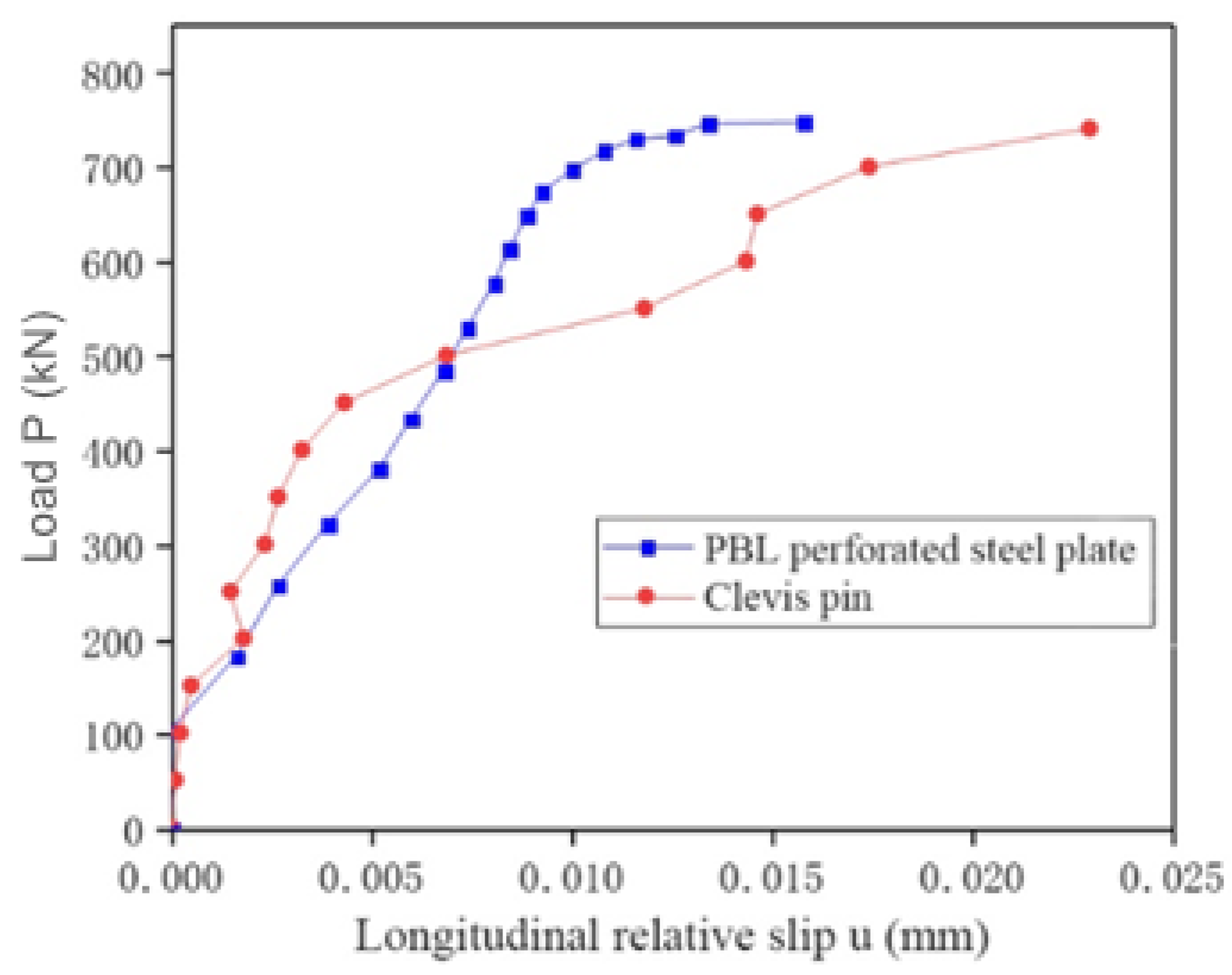
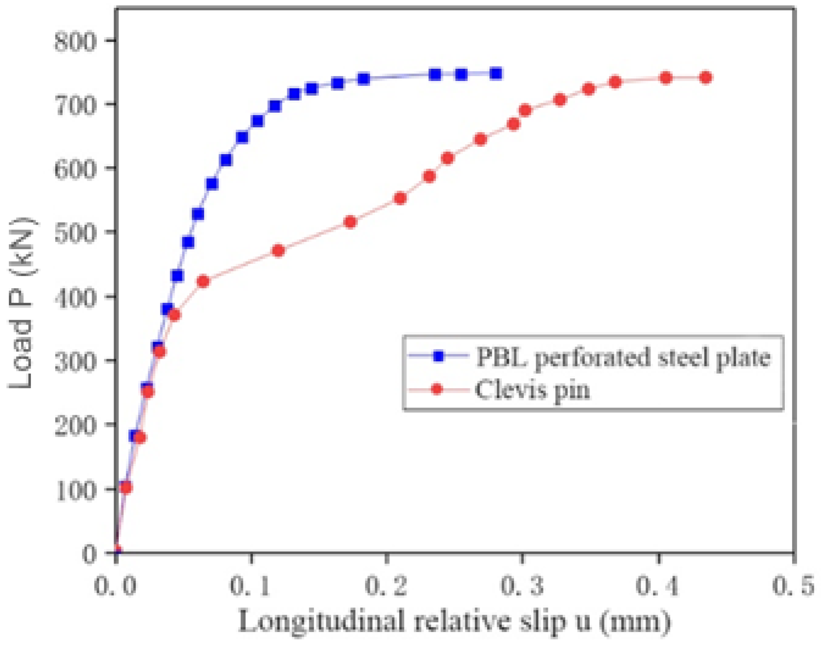
The relative slip and vertical peel data from the finite element simulations of two sets of corrugated steel–concrete composite deck slabs with PBL open-hole steel plate shear keys and pinned shear keys, respectively, were collated and analyzed, and the data were compared and analyzed as shown in
Figure 17,
Figure 18 and
Figure 19 and
Table 8.
It can be seen that, compared to the pinned shear keys, the maximum longitudinal slip in the span of the corrugated steel–concrete composite deck using PBL open-hole steel plate shear connection keys is only 0.0158 mm and the maximum longitudinal slip at the end of the slab is only 0.0230 mm, compared to 0.280 mm and 0.436 mm for the shear key combination. The load-slip curves of the composite deck plate show that the linear working phase of the PBL perforated steel plate with a continuous increase in load and little increase in slip is significantly longer than that of the pinned shear key. It is not until around 680 kN that the load-slip curve of the composite deck with PBL plates shows plasticity, whereas the plasticity of the pinned shear keys is already present at around 450 kN. It also shows that the PBL open-ended steel plates as rigid shear keys can increase the overall stiffness of the structure to a certain extent.
From
Figure 19 and the analysis of the vertical stripping data in
Table 8, the following can be obtained: with both the shear studs and the PBL open-hole steel plate, when the loading is less than 500 kN and 630 kN, respectively, the increase in the vertical stripping amount at the intersection of concrete and corrugated steel plate in the span is very small, less than 0.1 mm, and the peeling phenomenon is not obvious at this time. However, when the external load P continues to increase, the vertical stripping amount at the interface between the two increases sharply until the member reaches the ultimate bearing capacity and is damaged, at which time the peeling phenomenon is more obvious. The maximum vertical peel of the composite deck plate with PBL open-hole steel plate is 0.460 mm, which is 21% less than the 0.581 mm of the composite deck plate with the pinned shear key.
As can be seen from the above conclusions, the PBL open-cell steel plate, as a new form of shear connection bond, is indeed more resistant to slip and peeling than the pinned shear bond and is more effective in resisting the relative slip and vertical stripping between the corrugated steel and concrete.
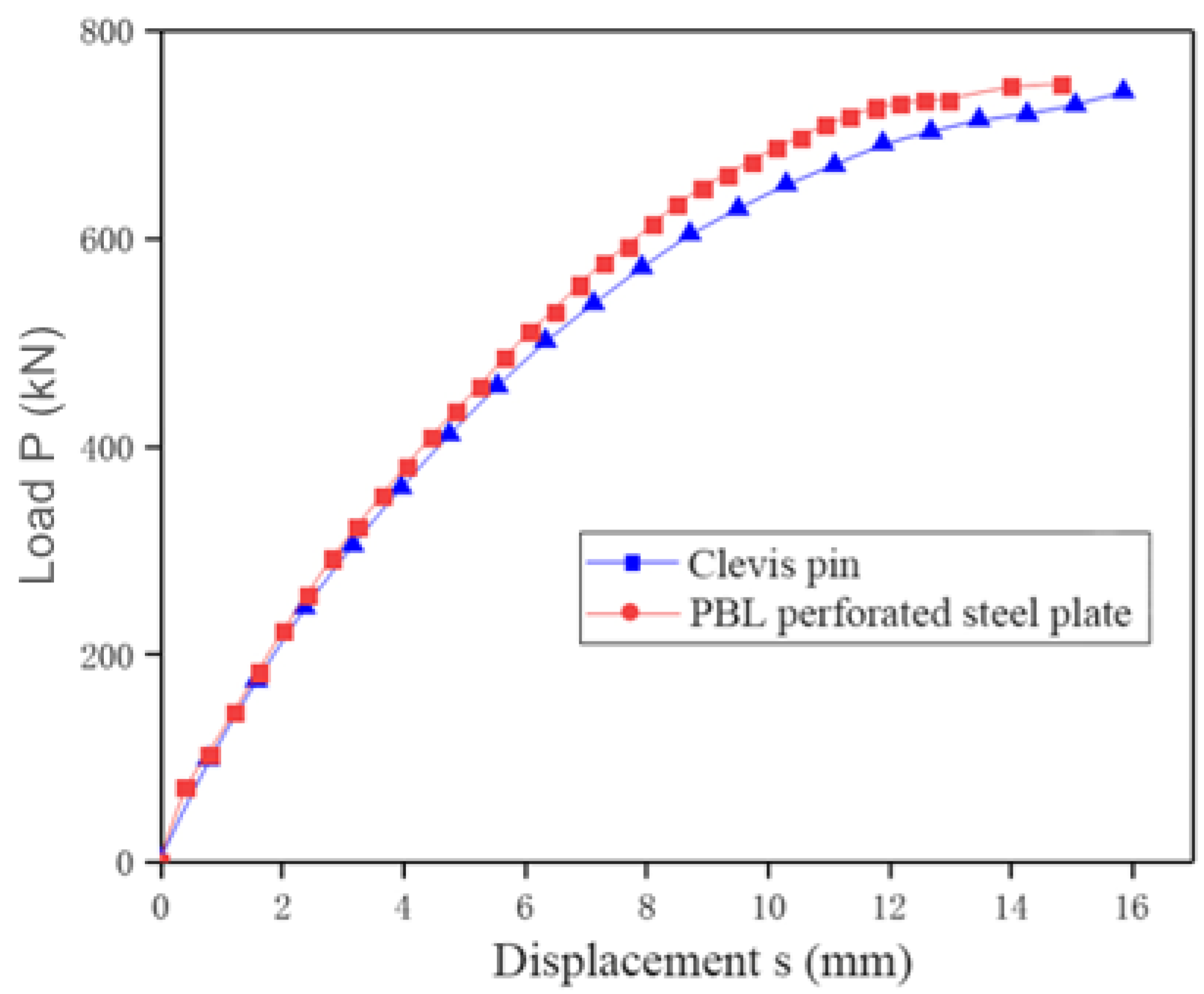
6. Comparative Study of the Flexural Load-Carrying Capacity of Combined Bridge Decks with Different Shear Keys in the Positive Section
The previous section discussed the comparison of the slip and peel resistance between PBL open plate shear keys and pinned shear keys. The analysis was carried out in terms of the overall structural forces to investigate if there are differences between the two in terms of enhancing the overall force performance of the combined deck slabs. The positive section flexural load carrying capacity of the two sets of combined deck slabs from the finite element model analysis in the previous section was analyzed to produce the graphs shown in
Table 9 and
Figure 20.
The ultimate load-carrying capacity of the corrugated steel–concrete deck with PBL shear keys is 747.3 kN, and the deflection under three times the wheel load is 1.82 mm; the two figures for the pinned deck are 740.6 kN and 1.90 mm, respectively. This shows that the ultimate load-carrying capacity of the PBL deck with perforated steel plates is not substantially higher than that of the shear studs and that the increase in the overall stiffness of the structure with perforated steel plates is also very limited, making the difference in deflection values between the two under the same load not significant.
To study the effect of different forms of shear keys on the stresses in the concrete during the loading process, the concrete at point a, located at the same position around the shear key in the span (5 mm to the right of the shear key), was selected as the object of study in both sets of combined deck slabs to investigate the stress state during the loading process. The load–stress curve of the concrete at point a is shown in
Figure 21.
As can be seen from
Figure 21, when the PBL open steel plate is used as the shear connection key, the stresses in the concrete around the shear key grow faster compared to the concrete around the pinned shear key. This means that the stresses in the concrete around the shear key reach their ultimate state when the external load P is around 500 kN. It is assumed that this phenomenon is due to the large stiffness gradient in the structure around the shear key caused by the addition of the perforated steel plate and the change in the local cross-sectional area of the concrete due to the perforation of the steel plate, which results in a local stress concentration in the concrete around the perforated steel plate of the PBL.
Therefore, it can be concluded from the above analysis that there is little difference in the overall ultimate load-carrying capacity of the composite deck structure whether PBL perforated steel plates or pins are used as shear connection keys for the composite deck. And the point to be noted in the engineering design is: when using rigid shear keys such as PBL open-hole steel plates as the shear keys of the combined deck, attention should be paid to the phenomenon of local crushing of the concrete due to stress concentration.
7. Conclusions
The new combined steel–concrete deck structure has many advantages over traditional reinforced concrete decks and steel-composite decks in terms of stress performance. Parametric analysis and structural design optimization were carried out to ensure optimum performance. ABAQUS was used to model and study the shear resistance of the pinned shear connection keys in composite decks and to investigate the effect of different types of shear connection keys on the load-bearing properties of composite decks.
(1) The individual ultimate shear load capacity of the shear studs as shear keys in the finite element simulation of the launch experiment reached 103.4 kN, with a shear stiffness of 370.5 kN/mm. The shear studs’ shear keys can play a better role in transmitting the shear force in the steel–concrete composite structure, and the whole member also reflects the obvious ductility characteristics in the shear test. Therefore, it is still worthwhile to promote the use of shear studs as shear connection keys for new deck structures where the direction of shear action is not clear enough.
(2) The strain, stress data, and load–displacement curves of the corrugated steel–concrete composite deck slab under stress were studied, and the reasonableness of its stress mechanism was analyzed. The conclusion is that the concrete and the bending steel plates can work well together under stress.
(3) The corrugated steel–concrete deck slab has greater load-bearing capacity and stiffness than the traditional reinforced concrete deck slab and the steel–concrete deck slab but has less dead weight than the latter two.
(4) The finite element modeling of the shear studs was carried out in combination with the combined structure of corrugated steel–concrete to investigate the stress and damage mechanisms of the shear studs under the action of shear force, and the influence of the height of the shear studs on the shear load capacity of the shear studs was investigated by studying the structural parameters of the shear studs with height-to-diameter ratios . It is concluded that the shear load capacity of the shear studs increases with the increase in the height-to-diameter ratio for different diameters of the shear stud shear joint, with the range of increase being between 2% and 23%. However, when the diameter of the shear studs exceeds 22 mm, the increase in the ultimate shear capacity of the shear studs slows down as the height-to-diameter ratio increases. Therefore, in the actual design of the composite deck, the height-to-diameter ratio of the shear studs should be in the range of 9 to 12.
(5) The effect of pinned shear keys and PBL open-cell steel plate shear keys on the slip and peel resistance and the positive section load-bearing performance of the composite deck structure were investigated in conjunction with the form of a corrugated steel–concrete composite deck slab. The results show that the maximum longitudinal slip at the end and mid-span of the PBL perforated steel plate is only 0.28 mm and 0.0158 mm, respectively, which is 31% and 36% less than the corresponding values for the PBL perforated steel plate. It can be seen that PBL perforated steel plates are more effective in resisting slip and peel than shear studs. There is little difference in the overall ultimate load-carrying capacity of the deck structure between the use of PBL perforated steel plates and pins as shear connection keys for the deck. When using a rigid shear key such as a PBL plate as the shear key for a composite deck, attention needs to be paid to the local crushing of the concrete due to stress concentration.

 ,
, 


