Abstract
Due to factors such as uneven guide rails and airflow disturbance in the hoistway, high-speed elevators may experience significant vibrations during operation. This paper proposes an optimized fractional-order PID (FOPID) method to suppress vibrations of high-speed elevators. First, an accurate horizontal vibration model is established for the elevator car, in which the car frame and body are separate. Then, taking the control cost and the system performance as objective functions, we obtained an optimized FOPID controller based on multi-objective genetic algorithm optimization. Finally, the effectiveness of the controller in reducing elevator vibration was verified through numerical simulation. The results indicate that the horizontal acceleration controlled by the FOPID controller is reduced by about 68% compared to the case without a controller and about 25% compared to the conventional PID controller.
1. Introduction
As the development of urban construction advances, towers have increased rapidly, and high-speed elevators increase correspondingly. The speed rise of elevators causes the horizontal vibration to be more obvious. Large horizontal vibrations can affect the comfort and safety of elevators, leading to a decrease in elevator lifespan. Therefore, the vibration suppression of elevators is a key issue in the field of elevator research, which is significant for the development of the elevator industry.
The main factors causing the vibration are the defects of the guide rail or the non-standard installation and the influence of the airflow in the shaft. Passive damping and active damping are common methods for suppressing the horizontal vibration of elevators [1]. The passive damping method generally suppresses vibration by optimizing the structure or the car parameters. However, due to the complexity of the elevator operation and multiple factors, the effect of passive damping to suppress vibration is difficult to meet the demand. The active damping applies the active control force through the corresponding actuator and suppresses vibration through control algorithms [2]. Active damping is better than passive damping in suppressing vibration and meeting the demand, but it will increase the cost. Due to low speed and small vibration, low-speed elevators usually do not use active damping methods. However, high-speed elevators cannot ignore the vibration caused by speed, so an active damping method is needed. The usual executive structure of the active damping method is the active guide shoe, which plays an important role in reducing vibration and improving elevator ride comfort. It can reduce vibration by the force generated by the actuator installed on the passive guide shoe opposite to the vibration direction. Due to their good effect and strong adaptability, guide shoes have become an effective means of suppressing elevator vibration.
Cao et al. [3] established a 6-degree of freedom (DOF) horizontal vibration model for an elevator car and proposed an H2/generalized H2 hybrid control strategy. The results prove that the control strategy is effective. Feng et al. [4,5] simplified the guide shoe as a spring-mass damping system, treating the car body and car frame as a rigid body. Zhang et al. [6] designed a new type of shock absorber using a linear motor and designed a PID controller that combines a linear prediction model with a backpropagation neural network. From the results, it can be seen that the proposed control method is superior to traditional proportional integral differential controllers in suppressing vibration. Chen et al. [7] designed an optimal guaranteed performance state feedback controller based on a linear convex optimization method to minimize the H2 performance index and achieve the specified H∞ performance level. This control strategy is effective in vibration suppression and improving elevator comfort. Although the above scholars have tried to suppress the horizontal vibration, they have ignored the impact of treating elevators as rigid bodies on vibration response. He et al. [8] designed a pneumatic active guide shoe and a fuzzy neural network intelligent vibration reduction controller based on the Mamdani model, which can effectively suppress the horizontal vibration of high-speed elevators. Santo et al. [9] established a 3-DOF elevator car model, derived a dynamic equation for the impact of rail deformation on it, and proposed an SDRE control strategy that can effectively control system effects and help maintain the integrity of elevator components. Wang et al. [10] established a more practical elevator car horizontal vibration control model, proposed a predictive sliding mode controller based on the adaptive fuzzy-based (PSMC-AF) and designed a fuzzy logic system (FLS) to approach the compound uncertainty disturbance term (CUDT) online. Zhang [11] used the FA-BP algorithm to train fuzzy neural network (FNN) auxiliary controllers, and the elevator experiments have demonstrated the effectiveness. Tussett et al. [12] adopted a linear quadratic regulator (LQR) control strategy to control the magnetorheological damper, and the results validate the effectiveness. Zhao et al. [13] proposed an acceleration feedback-based active control method to suppress the vibration of elevators. Numerical simulations have demonstrated the effectiveness of the method. Wang et al. [14] proposed a semi-active high-speed elevator car horizontal vibration reduction method based on the improved particle swarm algorithm, and it has been verified through experiments. Due to the complexity of the controller designed using the above method, problems such as high cost or difficult implementation conditions may arise in practical use. The idea of combining fractional calculus theory with PID controllers has brought a new type of PID controller, known as the FOPID controller [15]. As a product of the combination of fractional calculus and PID controllers, FOPID not only has the advantage of simple control structure, strong adaptability, and independence of the controlled object model but also has better performance due to the introduction of more parameters. However, the design difficulty of FOPID controllers increases [16,17]. Some analytical and heuristic methods have been used in the design of FOPID controllers in different fields [18,19]. Some scholars use different algorithms for the design of FOPID controllers. Ataşlar [20] optimized the parameters of the FOPID controller using the GWO PSO algorithm. Idir [21] proposed the improved artificial bee colony (IABC) low-order approximation (LOA)-based fractional order PID (IABC/LOA-FOPID). Silaa [22] used the gray wolf optimizer (GWO) and extended gray wolf optimizer (EGWO) to obtain the appropriate parameters of the FOPID controller. Mok [23] proposes a modified smoothed function algorithm (MSFA)-based method to tune the FOPID controller of the AVR system. Ahmeda [24] designed a FOPID controller based on ILC (iterative learning control). The results demonstrate the effectiveness of the FOPID controller. Currently, no scholars have applied FOPID to elevator vibration suppression.
Regarding the above issues, this paper establishes a model that treats elevators not as rigid bodies but with the car body and frame separate, and designs a FOPID controller. Selecting system performance and control cost as objective functions, a multi-objective genetic algorithm (MOGA) is used to optimize the controller parameters. Through MATLAB/Simulink simulation verification, the FOPID controller can effectively suppress elevator vibration, which has a better effect than PID controllers.
The main contributions and innovations of this paper are as follows:
- An optimization design model for elevator vibration suppression is established, and an optimized FOPID controller is designed to suppress horizontal vibration effectively.
- Selecting control cost and system performance as the objective functions of the optimization algorithm, MOGA is used to optimize the parameters of both the PID controller and FOPID controller.
- Through multiple iterations, the proposed optimized FOPID controller can achieve the expected system performance at a limited control cost, which can reduce the horizontal acceleration by about 68% compared to the case without a controller and about 25% compared to PID control.
The remainder of the article is arranged as follows. In Section 2, a dynamic model of the horizontal vibration of high-speed elevators is established. Section 3 proposes an optimized FOPID control method based on a multi-objective genetic algorithm. Section 4 proposes numerical results and validation. Section 5 provides concluding remarks.
2. Dynamic Model of Horizontal Vibration of High-Speed Elevator
The elevator car is composed of a car body and a car frame. The car body is connected to the car frame through support rubber, and the four guide shoes guide the elevator to move. The guide shoes and the support rubber work together to reduce vibration. The elevator car is a relatively complex multi-degree of freedom vibration system. Referring to the experimentally validated model [14], we optimized the complex model [25] to obtain an elevator model that meets our requirements. The car system is simplified to the following lateral vibration dynamics model, as shown in Figure 1.
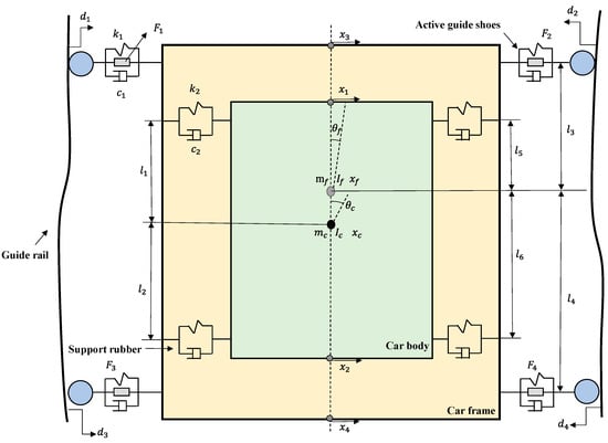
Figure 1.
Dynamic Model of Elevator Lateral Vibration.
In the model, and are the car body’s mass and rotational inertia, and are the car frame’s mass and rotational inertia. and are the stiffness and damping coefficient of the active guide shoes, while and are the stiffness and damping coefficients of the supporting rubber. The active control force is ; The guide shoe displacement excitation is ;
is the horizontal displacement of corresponding points. , are the displacement of the car body’s barycenter and frame’s barycenter, respectively. , are the rotation angle of the car body’s barycenter and frame’s barycenter, respectively.
, is the distance between the rubber and the car body’s barycenter. , are distance between active guide shoes and the car frame’s barycenter.
To facilitate writing, the following transformations are made:
Including:
Define transformation matrix:
and represents the distance from the rubber to the car frame’s barycenter.
The dynamic equations for the car body and car frame in the horizontal direction are as follows:
In Equations (6) and (7), , , , , , , , , .
By selecting appropriate state variables, the above motion equation can be transformed into a system state equation. In this paper, the state equation is obtained by fusing the differential terms of rail displacement excitation into the state equation.
The lateral vibration state equation can be expressed as:
The state variable of the system is: ; the active control of the system is: ; the disturbance of the system is: ; the output of the system is: ; where:
In Equation (10), represents the acceleration of the car body, represents the offset from the centerline, represents the offset between the car body and frame.
In Equations (8) and (9):
3. Optimized FOPID Control Method Based on MOGA
3.1. Control Problem Description
The horizontal vibration suppression model of the elevator is shown in Figure 2:
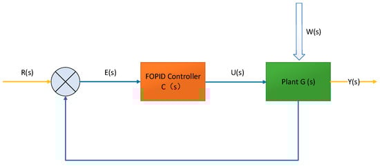
Figure 2.
Control model block diagram.
In Figure 2, G (s) is the elevator vibration dynamics model established in the previous section, C (s) is the designed FOPID controller, and W (s) is the disturbance caused by rail irregularities.
The sensitivity of the human body to horizontal vibration is higher than that of vertical vibration[14]. Therefore, when suppressing vibration, it is sufficient to use the horizontal vibration as the control target.
The RMS of acceleration at the car body’s bottom and the relative displacement is selected as . The RMS of the control force output by the actuator is taken as the control cost .
where , , , are the regularization coefficients. We can adjust , , to change the weight of the corresponding output in the objective function . is used to adjust for subsequent analysis.
The multi-objective integrated design model for elevator lateral vibration control is as follows:
where represents the corresponding parameter of C (s), including Kp, Ki, Kd, the integral order λ and differential order , constraint represents the maximum real part of the eigenvalue of to ensure system stability; and represent the corresponding parameters’ upper and lower boundaries.
3.2. Fractional Order PID Controller
There are two main definitions of fractional calculus: Riemann-Liouville and Grunwald-Letnikov definitions.
Riemann-Liouville definition:
In Equation (13), α is the order of the calculus, and a and t are the upper and lower limits of the integration. For < α < m, m∈ N, where is Euler’s gamma function.
The Laplace transform of the RL fractional derivative is expressed as follows:
When the initial condition is 0, Equation (12) can be expressed as:
FOPID’s transfer function is as follows:
The integral order λ and differential order can take any value from 0 to 1. Conventional PID controllers are special cases where both integral and differential orders are taken as 1. The two order parameters bring more freedom to the controller’s adjustment. The parameter plane of the FOPID controller is shown in Figure 3.
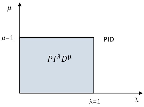
Figure 3.
Fractional PID controller plane.
3.3. Multi-Objective Genetic Algorithm
The vibration suppression problem of elevators is transformed into a multi-objective optimization problem shown in Equation (16), which achieves optimal system performance with minimal control costs. FOPID controllers introduce more parameters, which brings more degrees of freedom, but also increases the difficulty of controller design. Traditional PID controller design methods are challenging to achieve the desired results for FOPID controllers. Therefore, MOGA is selected to optimize the parameters of FOPID controllers.
Definition 1.
Pareto solution.
Select the objective function as , ; For two solution vectors and located in the solution space, , and , , It can be considered that the solution Dominant Solution , or solve dominates solution . If there is no other solution in the solution space that is superior to this solution, the solution is called a Pareto solution. A Pareto optimal solution set is represented as follows:
where is the solution vector and is the solution space.
Definition 2.
Noninferior solution sorting.
Noninferior solution ranking is important in MOGA, which determines the search direction of optimization algorithms. The specific process is as follows: 1. Let all solution spaces be S and compare them to find a noninferior solution set . 2. Make S = S −. Repeat the comparison process to find the non-inferior solution set . 3. Repeat process 2 until S is an empty set. is called the first order noninferior solution, is called the second level noninferior solution, and so on. Obviously, the solution in is the best individual.
The process of MOGA is shown in Figure 4:
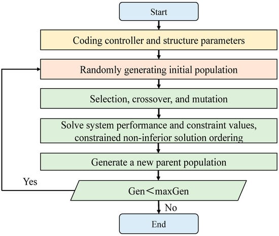
Figure 4.
Flow chart of multi-objective genetic algorithm.
As mentioned in Section 3.1, the vibration suppression problem of elevators can be simplified into two control objectives: system performance and control cost. The parameters of the controller (Kp, Ki, Kd, etc.) are the variables that need to be optimized. Take two control objectives as the objective functions of a multi-objective genetic algorithm, and iteratively optimize all controller parameters as the population of the algorithm, ultimately obtaining the optimal controller parameters.
4. Numerical Results and Validation
To verify the effectiveness, a model was built using MATLAB/Simulink for simulation verification. The system is built in Simulink based on the state space equations given in Equations (8) and (9), and the simulation is completed by using the FOMCON toolbox [26] to import the FOPID controller.
4.1. Model Parameters
The specific parameters are shown in Table 1.

Table 1.
Parameters of the elevator model.
Most of the energy excited by the guide rail is located at low frequencies. The white noise signal passing through the low-pass filter is selected to simulate actual rail excitation. To approach the actual excitation signal of the guide rail more closely, select the appropriate amplitude of white noise. The white noise signal is output through the model in Simulink. Set the noise power to , the sample time to , and the seed to 23,341. The transfer function of the low-pass filter [26] is shown in Equation (18):
In practical applications, both the magnitude of the control force that activates the actuator and the travel of the mechanism should be considered while suppressing elevator vibration. Therefore, control costs should be limited so that the designed controller can meet actual needs. The optimal design model obtained after limiting the control costs is as follows:
The corresponding regularization coefficients are: = 1000, , = 0.02, = 0.001.
When using the MOGA algorithm to optimize the parameters, it is necessary to determine the search interval of the controller parameters first. Due to the elevator system being a complex MIMO system, the root locus method or the Routh Hurwitz method used to determine the search interval of the SISO system is no longer applicable. The initial interval of MIMO system parameters is generally determined using random area testing or decision statistics.
The FOPID controller designed in this paper is similar in structure to a PID controller. All parameters of the controller are nonnegative, and the lower bound of the initial search interval does not need to be searched. However, the designed controller has many parameters; it is hard or even unable to find a solution when all parameters are tested in a random area together. Referring to the parameter tuning method of conventional PID controllers, the parameter range of the designed controller is determined step by step, and the parameter range is gradually optimized in the order of proportional parameters, integral parameters, and differential parameters, as shown in Figure 5.
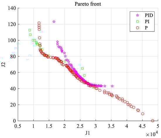
Figure 5.
Parameter interval optimization process.
4.2. Results and Discussion
According to the above process, the parameters of the controller are optimized by using MOGA. Kp, Ki, Kd, the integral order λ, and differential order are chosen as variables which are all nonnegative. The upper bounds for λ and are 1. The upper bounds for Kp, Ki, and Kd change in [1,1]. The population size is 400, and the maximum algebra is 50. The function tolerance is . The frontier of the Pareto solution obtained through the optimization is shown in Figure 6. The horizontal and vertical axes represent the two objective functions of the optimization algorithm. The horizontal axis represents system performance, while the vertical axis represents control cost. The curve in the Figure 6 consists of all feasible solutions obtained through optimization, namely the Pareto solution set, with each point representing a set of feasible controller parameters. Select three points , , on this curve. Three sets of controller parameters are brought into Simulink for simulation, and their differences in time domain response can be analyzed.
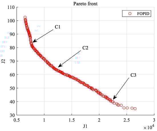
Figure 6.
Pareto solution front.
Figure 7 shows a comparison of the bottom horizontal acceleration of the car body with different controllers (, , ) and without control. According to the curve in Figure 7, compared to the case without control, the three groups of controllers can reduce the horizontal acceleration response. In the curve shown in Figure 6, the point near the vertical axis has better system performance and greater control costs. The controller parameters can be reasonably selected based on actual needs.
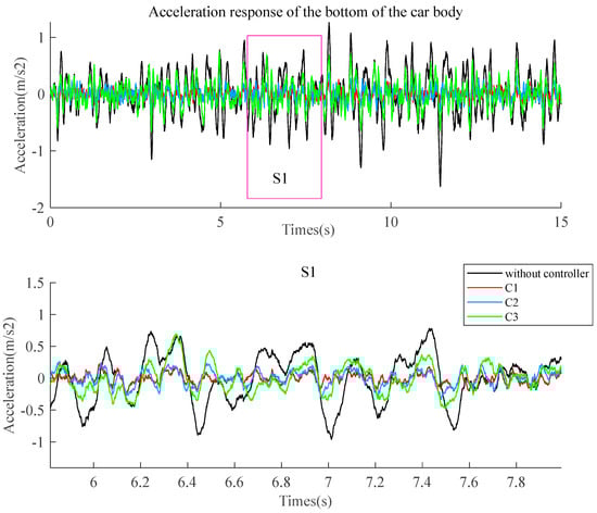
Figure 7.
System acceleration comparison.
Figure 8 compares the relative centerline displacement of the car frame bottom under three sets of controllers and the situation without a controller. The image curve shows that the controller has almost no effect on the relative displacement because the relative displacement occupies a small weight in the system performance . The controller does not increase the displacement, which meets the control expectations.
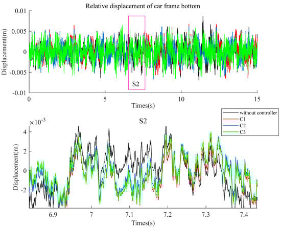
Figure 8.
Comparison of relative displacement of car frame bottom.
Figure 9 compares the bottom offset between the car body and frame under the control of three sets of controllers and without control. The curve results show that under the control of three sets of controllers (C1/C2/C3), the relative offset of the system decreases compared to the case without controllers.
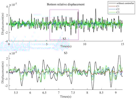
Figure 9.
Comparison of relative offset between car body and car frame.
Figure 10 compares the magnitude of vibration without a controller and controlled by optimized FOPID controller C2. The vibration of the elevator is mainly caused by the excitation of the guide rail, and the energy of the guide rail excitation is mainly concentrated in the low-frequency region. Figure 10 shows that the optimized FOPID controller can effectively reduce the vibration amplitude of the elevator compared to no controller. Figure 11 compares the output forces of three group controllers (C1/C2/C3). The output force corresponding to the controller is proportional to the control cost.
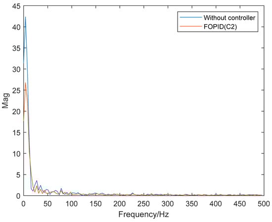
Figure 10.
Comparison of vibration spectrum diagram.
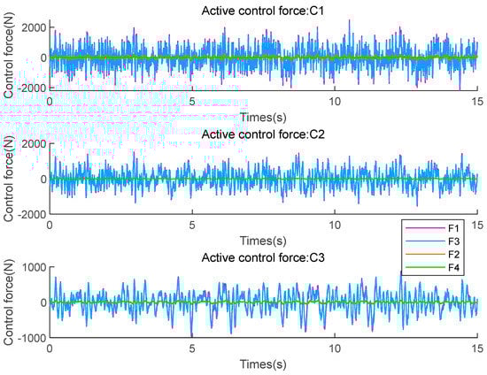
Figure 11.
Comparison of active control force.
As shown in Table 2, the RMS values of system performance indicators, control cost, horizontal acceleration, and other parameters are compared. Taking controller C2 as an example, compared with those without a controller has been reduced by 68.46%, and the horizontal acceleration of the main control target car bottom has been reduced by 68.47%. The results show that the designed FOPID controller effectively suppresses elevator vibration compared to the uncontrolled situation, and the inhibition effect is related to the control cost.
Table 2.
Comparison of corresponding indicators.
Using the same optimization algorithm to optimize the conventional PID controller, a Pareto solution set like the FOPID controller is obtained (Figure 12). The two curves are shown below. Using the controller C2 designed above as the comparison object, the control effects between PID and FOPID are compared and analyzed.
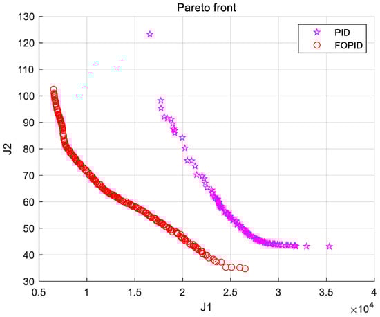
Figure 12.
Comparison of Pareto front between PID and FOPID.
The control cost of the designed FOPID controller C2 is 77. Select a point on the PID curve where the control cost is similar and bring the corresponding parameters and PID controller into the model for simulation analysis. Figure 13 compares the horizontal acceleration under the control of two types of controllers, respectively. From the curve in Figure 13, compared to the PID controller, the horizontal acceleration controlled by the FOPID controller is smaller. Figure 14 compares the displacement at the car frame’s bottom relative to the centerline under two control situations. The two controllers have almost the same control effect on the bottom displacement relative to the centerline. Figure 15 shows the bottom offset between the car body and the car frame under two control situations. From Figure 15, the relative deviation of FOPID is slightly smaller than that of PID. Figure 16 compares the output forces of the active mechanism under the two controllers. From Figure 16, the output forces of the two controllers are almost the same because they have similar control costs.
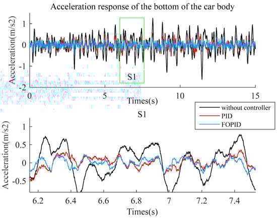
Figure 13.
Comparison of acceleration response of PID and FOPID.
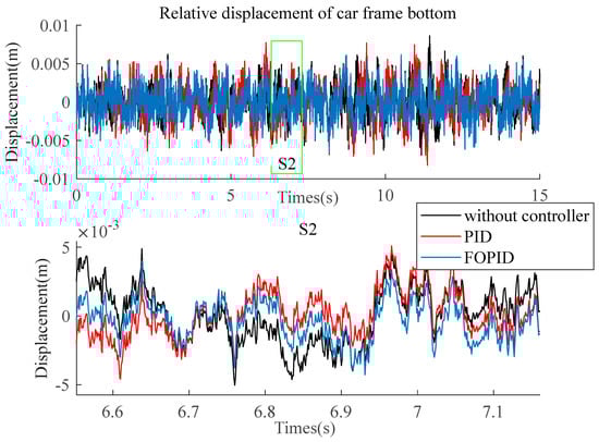
Figure 14.
Comparison of relative displacement of PID and FOPID.
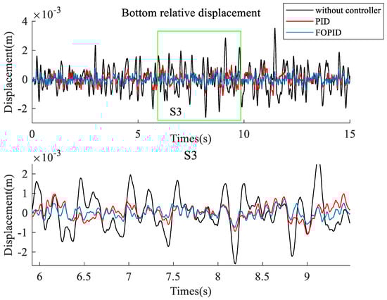
Figure 15.
Comparison of bottom offset of PID and FOPID.
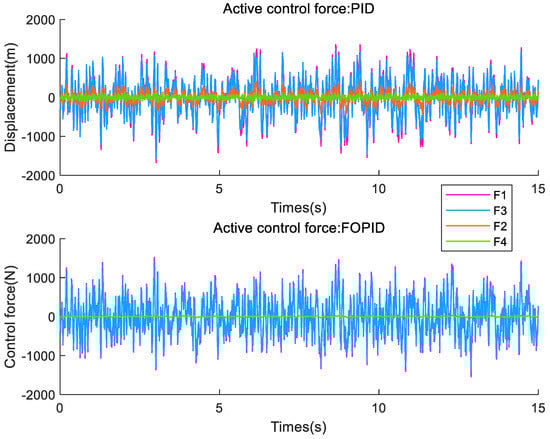
Figure 16.
Comparison of active control force of PID and FOPID.
To sum up, both controllers can suppress elevator vibration, but when the output force is basically equal, the parameters such as elevator acceleration and car offset under optimized FOPID controller control are superior to optimized PID control. As shown in Table 3, comparing the RMS of system performance indicators, control cost, horizontal acceleration, and other parameters under the two control conditions, compared to the PID controller, of FOPID controller decreased by 24.9%, the horizontal acceleration at the bottom of the car body decreased by 24.97%, the relative displacement at the bottom of the car frame decreased by 13.63%, and the relative bottom displacement between the car body and frame decreased by 27.71%. It can be found that FOPID is superior to PID control.
Table 3.
Comparison of corresponding indicators between PID and FOPID(C2).
5. Conclusions
To suppress elevator vibration caused by rail irregularities, a FOPID controller optimized based on MOGA is proposed for elevator car systems using ARG active guide shoes. The main conclusions are as follows:
- Considering elevators’ vibration characteristics during actual operation, a dynamic model of the elevator with the car body and frame separated is established. White noise with a low-pass filter is used to simulate rail irregularities, and the simulation experiment is more accurate.
- An optimization design model for elevator vibration suppression is established, and MOGA is used to optimize the FOPID controller to limit the control cost and ensure the feasibility of the designed controller.
- From the results, the horizontal acceleration of the system has been reduced by 68% under optimized FOPID control compared to no control and reduced by about 25% compared to the optimized PID control, fully demonstrating the effectiveness of the designed controller.
Author Contributions
Conceptualization, R.T., C.Q., M.Z., S.X., J.T. and C.L.; Methodology, R.T., C.Q., S.X., J.T. and C.L.; Software, M.Z.; Validation, R.T. and M.Z.; Investigation, S.X.; Resources, M.Z. and J.T.; Data curation, J.T.; Writing—original draft, R.T. and C.Q.; Writing—review & editing, C.Q.; Project administration, C.L.; Funding acquisition, C.L. All authors have read and agreed to the published version of the manuscript.
Funding
This work was supported by Natural Science Foundation of China (Grant No. 51935007) and Shanghai Municipal Science and Technology Major Project (2021SHZDZX0102).
Institutional Review Board Statement
Not applicable.
Informed Consent Statement
Not applicable.
Data Availability Statement
Not applicable.
Conflicts of Interest
The authors declare no conflict of interest.
References
- Tao, R.; Xu, Y.; Deng, F.; Guo, S.; Wang, H. Feature extraction of an elevator guide shoe vibration signal based on SVD optimizing LMD. J. Vib. Shock. 2017, 36, 166–171. [Google Scholar]
- Qin, C.J.; Tao, J.F.; Liu, C.L. A novel stability prediction method for milling operations using the holistic-interpolation scheme. Proc. IMechE., Part C: J. Mech. Eng. Sci. 2019, 233, 4463–4475. [Google Scholar] [CrossRef]
- Cao, S.X.; He, Q.; Zhang, R.J.; Cong, D.S. Active Control Strategy of High-Speed Elevator Horizontal Vibration Based on LMI Optimization. Control Eng. Appl. Inform. 2020, 22, 72–83. [Google Scholar]
- Feng, Y.H.; Zhang, J.W. The modeling and simulation of horizontal vibrations for high-speed elevator. J. Shanghai Jiaotong Univ. 2007, 41, 557–560. [Google Scholar]
- Feng, Y.H.; Zhang, J.W. Study on active control strategy of horizontal vibrations of high-speed elevator. J. Syst. Simul. 2007, 19, 843–845. [Google Scholar]
- Zhang, Q.; Yang, Z.; Wang, C.; Yang, Y.; Zhang, R. Intelligent control of active shock absorber for high-speed elevator car. Proc. Inst. Mech. Eng. Part C J. Mech. Eng. Sci. 2018, 233, 3804–3815. [Google Scholar] [CrossRef]
- Chen, C.; Zhang, R.; Zhang, Q.; Liu, L. Mixed H2/H∞ guaranteed cost control for high speed elevator active guide shoe with parametric uncertainties. Mech. Ind. 2020, 21, 502. [Google Scholar] [CrossRef]
- He, Q.; Zhang, P.; Cao, S.; Zhang, R.; Zhang, Q. Intelligent control of horizontal vibration of high-speed elevator based on gas–liquid active guide shoes. Mech. Ind. 2021, 22, 2. [Google Scholar] [CrossRef]
- Santo, D.R.; Balthazar, J.M.; Tusset, A.M.; Piccirilo, V.; Brasil, R.; Silveira, M. On nonlinear horizontal dynamics and vibrations control for high-speed elevators. J. Vib. Control 2016, 24, 825–838. [Google Scholar] [CrossRef]
- Wang, H.; Zhang, M.; Zhang, R.; Liu, L. Research on predictive sliding mode control strategy for horizontal vibration of ultra-high-speed elevator car system based on adaptive fuzzy. Meas. Control 2021, 54, 360–373. [Google Scholar] [CrossRef]
- Zhang, H.; Zhang, R.; He, Q.; Liu, L. Variable Universe Fuzzy Control of High-Speed Elevator Horizontal Vibration Based on Firefly Algorithm and Backpropagation Fuzzy Neural Network. IEEE Access 2021, 9, 57020–57032. [Google Scholar] [CrossRef]
- Tusset, A.M.; Santo, D.R.; Balthazar, J.M.; Piccirillo, V.; Santos LC, D.; Brasil, R.M. Active vibration control of an elevator system using magnetorheological damper actuator. Int. J. Nonlinear Dyn. Control 2017, 1, 114–131. [Google Scholar] [CrossRef]
- Zhao, M.M.; Qin, C.J.; Tang, R.; Tao, J.F.; Xu, S.; Liu, C.L. An Acceleration Feedback-Based Active Control Method for High-Speed Elevator Horizontal Vibration. J. Vib. Eng. Technol. 2023, 1–14. [Google Scholar] [CrossRef]
- Wang, Z.; Qiu, L.; Zhang, S.; Su, G.; Zhu, L.; Zhang, X. High-speed elevator car system semi-active horizontal vibration reduction method based on the improved particle swarm algorithm. J. Vib. Control 2022. [Google Scholar] [CrossRef]
- Zamani, A.-A.; Etedali, S. Optimal fractional-order PID control design for time-delayed multi-input multi-output seismic-excited structural system. J. Vib. Control 2021, 29, 802–819. [Google Scholar] [CrossRef]
- Zeng, G.-Q.; Chen, J.; Dai, Y.-X.; Li, L.-M.; Zheng, C.-W.; Chen, M.-R. Design of fractional order PID controller for automatic regulator voltage system based on multi-objective extremal optimization. Neurocomputing 2015, 160, 173–184. [Google Scholar] [CrossRef]
- Cao, J.Y.; Cao, B.G. Design of fractional order controller based on particle swarm optimization. Int. J. Control Autom. Syst. 2006, 4, 775–781. [Google Scholar]
- Birs, I.; Folea, S.; Prodan, O.; Dulf, E.; Muresan, C. An experimental tuning approach of fractional order controllers in the frequency domain. Appl. Sci. 2020, 10, 2379. [Google Scholar] [CrossRef]
- Mohanty, D.; Panda, S. Modified salp swarm algorithm-optimized fractional-order adaptive fuzzy PID controller for frequency regulation of hybrid power system with electric vehicle. J. Control Autom. Electr. Syst. 2021, 32, 416–438. [Google Scholar] [CrossRef]
- Ataşlar-Ayyıldız, B. Robust Trajectory Tracking Control for Serial Robotic Manipulators Using Fractional Order-Based PTID Controller. Fractal Fractional. 2023, 7, 250. [Google Scholar] [CrossRef]
- Idir, A.; Canale, L.; Bensafia, Y.; Khettab, K. Design and Robust Performance Analysis of Low-Order Approximation of Fractional PID Controller Based on an IABC Algorithm for an Automatic Voltage Regulator System. Energies 2022, 15, 8973. [Google Scholar] [CrossRef]
- Silaa, M.Y.; Barambones, O.; Derbeli, M.; Napole, C.; Bencherif, A. Fractional Order PID Design for a Proton Exchange Membrane Fuel Cell System Using an Extended Grey Wolf Optimizer. Processes 2022, 10, 450. [Google Scholar] [CrossRef]
- Mok, R.; Ahmad, M.A. Fast and optimal tuning of fractional order PID controller for AVR system based on memorizable-smoothed functional algorithm. Eng. Sci. Technol. Int. J. 2022, 35, 101264. [Google Scholar] [CrossRef]
- Jan, A.Z.; Kedzia, K.; Abbass, M.J. Fractional-Order PID Controller (FOPID)-Based Iterative Learning Control for a Nonlinear Boiler System. Energies 2023, 16, 1045. [Google Scholar] [CrossRef]
- Fu, W.J. Research on Car Lateral Vibration Suspensions for Super High Speed Elevators. Ph.D. Dissertation, Shanghai Jiao Tong University, Shanghai, China, 2008. [Google Scholar]
- Tepljakov, A.; Petlenkov, E.; Belikov, J. (Eds.) A Flexible MATLAB Tool for Optimal Fractional-order PID Controller Design Subject to Specifications. In Proceedings of the 31st Chinese Control Conference, Hefei, China, 25–27 July 2012. [Google Scholar]
Disclaimer/Publisher’s Note: The statements, opinions and data contained in all publications are solely those of the individual author(s) and contributor(s) and not of MDPI and/or the editor(s). MDPI and/or the editor(s) disclaim responsibility for any injury to people or property resulting from any ideas, methods, instructions or products referred to in the content. |
© 2023 by the authors. Licensee MDPI, Basel, Switzerland. This article is an open access article distributed under the terms and conditions of the Creative Commons Attribution (CC BY) license (https://creativecommons.org/licenses/by/4.0/).