Abstract
This article presents the design of a uni-planar MIMO antenna system for sub-6 GHz 5G-enabled smartphones. The MIMO antenna designed comprises four loop-shaped radiators placed at each corner of the mobile phone board, which follows the principle of pattern diversity. The single-antenna element resonates at 3.5 GHz, its impedance bandwidth is noted to be 1.28 GHz (3–4.28 GHz) for S −6 dB, and it is equal to 720 MHz (3.18–3.9 GHz) for S −10 dB. For a single-antenna element, a peak gain of 3.64 dBi is observed with an antenna efficiency of >90%. The isolation of >10 dB between antenna elements is achieved for the MIMO configuration. Furthermore, the MIMO antenna designed provides enough radiation coverage to support different sides of the mobile phone board, which is an important feature for future 5G-enabled handsets. In addition, the impacts of human hands and heads on MIMO antenna performance are investigated, and acceptable performance in the data and conversation modes is observed.
1. Introduction
For fifth-generation (5G) communication, most research societies are concentrating on obtaining high throughput and high data rates at a cheap cost [1,2]. It is predicted that the 5G systems will have a data rate 1000 times faster compared with the fourth-generation (4G) communication systems. Such a high data rate can be achieved with the help of multiple-input multiple-output (MIMO) technology [3,4]. In MIMO, the data rate can be improved by reducing multipath fading or by utilizing multiple independent channels. One of the major keys to boosting the channel capacity is to design several antennas for each channel [4]. The MIMO antenna must have a low mutual coupling, which is a prerequisite for a 5G mobile communication system [4]. Moreover, the 5G MIMO antennas can offer better diversity and multiplexing gain [5], which leads to enhanced channel capacity [6].
In the literature, several MIMO antennas have been presented for sub-6 GHz applications. In [7], an eight-element MIMO structure was developed for the 3.5 GHz spectrum. A symmetrical open-fork slit antenna with an L-shaped feeding strip was designed. This configuration offers isolation of >17.5 dB between antenna elements, but the design suffers because of poor antenna efficiency. The same kind of configuration with a rectangular-shaped slot was presented in Ref. [8]. The MIMO arrays consisted of two kinds of antenna elements for different frequency operations. Two elements of the same configuration were placed on the top and bottom corners of the printed circuit board (PCB) for 2G/3G/4G communication, while eight-elements meant to operate at 3.5 GHz were placed on the left and right sides of the PCB. The authors in [9] designed an eight-port broadband MIMO antenna for sub-6 GHz services. The single antenna of the MIMO system was made up of a 50 feed line with an open circuit tuning stub, a slot on the metal frame, and a U-shaped slot on the ground plane. The MIMO antenna provided a broadband response in the frequency range of 3.3–6 GHz. In [10], a monopole slotted MIMO antenna was presented for the 2.6/3.5 GHz bands. The four metal frame-based antennas fed using an L-shaped feed line were positioned in the middle of the PCB, while the other elements were placed on the top and bottom sides of the PCB.
In [11], a MIMO antenna array was designed for 3.5 GHz 5G smartphone applications. The array was made up of two distinct ways: one was an L-shaped coupled-fed array and the other was a U-shaped loop array, both of which were mounted on the smartphone’s metal frame. For isolation enhancement, the authors created an inverted-I slot and a neutralization line between the antenna components, resulting in 15 dB of isolation in the operational bandwidth. In [12], a dual-polarized diamond ring slot-based MIMO antenna was designed for 5G massive MIMO applications. Four dual-fed slot elements were placed on each corner of the mobile phone PCB. An L-shaped microstrip feed line was used to feed the slot elements. The designed antenna element offered a stable gain of 3 dBi for the band of interest and >80% radiation and total efficiencies. In addition, an isolation of more than 20 dB was observed within the operating range. In [13], the same kind of configuration was utilized to design MIMO antenna array for sub-6 GHz applications. In the presented configuration, a circular-ring resonator was etched from the ground plane and fed using orthogonally placed microstrip feed lines. The authors also designed a multi-band MIMO antenna by replacing the conventional microstrip feed line with a fork-shaped feed line.
In [14], an eight-port MIMO antenna based on an I-shaped element was developed for IoT and 5G technologies. To provide space for additional components, the cellphone’s metal frame was constructed to accommodate the antenna components. The antenna was found to resonate effectively in the 3.5 GHz frequency band. The MIMO antenna offers 13 dB of isolation between array elements, with a gain of 4 dBi and an antenna efficiency of more than 40%. In [15], an integrated MIMO antenna system for LTE and millimeter-wave frequency bands was designed. The designed antenna structure comprised two elements for LTE communications and four elements for 5G millimeter-wave communication. A modified rectangular radiator was utilized for both frequency bands. In addition, defects in the ground plane were introduced using rectangular and circular shapes. The designed antenna element provides resonance for the 5.5 GHz frequency band. A uni-planar sub-6 GHz MIMO loop antenna array was developed in [16]. The antenna antennas were organized in such a way so that they could offer both polarization and pattern diversity. Furthermore, the improvement in isolation was achieved by designing an arrow-shaped strip between the antenna elements. In [17,18], the authors designed a co-planar waveguide (CPW)-fed MIMO antenna array for sub-6 GHz applications. For the design, an L-shaped and T-shaped radiation elements were selected. By utilizing CPW technique, an isolation of >15 dB was achieved in the band of interest.
The abovementioned MIMO antennas have some limitations in terms of non-planar configurations, large size, and complex structures. In addition, these antennas suffer due to low radiation efficiency, which ultimately leads to poor antenna gain. To accommodate the drawbacks of previously published designs, this research presents a four-element uni-planar MIMO antenna system for 5G smartphone applications. For a single antenna, a loop-shaped element is chosen. The radiation elements are arranged at each corner of the PCB, which follows the principle of pattern diversity and makes room for other smartphone components. The results show that the designed MIMO antenna offers wideband response in the 3.5 GHz frequency band. The intended MIMO topology has low mutual coupling between antennas, resulting in a low envelope correlation coefficient (ECC) and high diversity gain (DG). Moreover, the proposed MIMO antenna offers an efficiency of >90%.
2. Proposed Uni-Planar MIMO Antenna
The proposed sub-6 GHz MIMO antenna’s design is shown in Figure 1. A low-cost FR-4 substrate is used for MIMO antenna design. The thickness of the substrate is chosen to be 1.6 mm and has a relative permittivity of 4.4. To save space on the PCB, a loop-shaped structure was used for the antenna design [19]. At 3.5 GHz, the electrical length of a radiator is approximately equal to 1, where is the guided wavelength. Therefore, the optimized electrical length of an antenna element is noted to be ≈45.5 mm, while the line width is equal to 1 mm. It is worth noting that a single antenna element can occupy a maximum area of 14.5 × 12 mm.
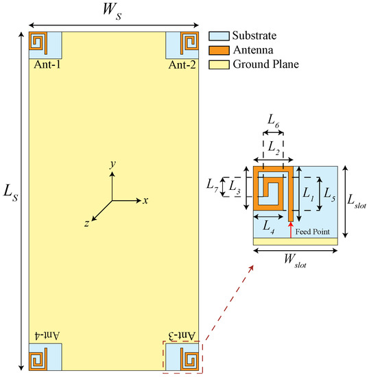
Figure 1.
Design of the proposed sub-6 GHz MIMO antenna.
The MIMO antenna, shown in Figure 1, comprises four loop-shaped radiators placed at each corner of the mobile phone PCB. The ground plane is placed on the same plane as the radiation elements. The design parameters of the proposed MIMO antenna are illustrated in Figure 1, while the optimized values are given in Table 1.

Table 1.
Optimized parameters of the sub-6 GHz MIMO antenna (in mm).
2.1. Characteristics of Single-Antenna Elements
The single MIMO element is designed and simulated in the commercially available electromagnetic software CST Microwave Studio. For excitation of the antenna element, a 50 discrete port is utilized. Figure 2 shows the simulated reflection coefficient () of a single antenna element. It is observed that the antenna element resonates well in the 3.5 GHz frequency band and provides a wideband response. The −6 dB and −10 dB impedance bandwidths are noted to be 1.28 GHz (3–4.28 GHz) and 720 MHz (3.18–3.9 GHz), respectively.
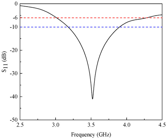
Figure 2.
Simulated characteristics of a single-antenna element.
The of the proposed antenna can be adjusted by changing some parameters of the antenna. For a particular design, the parameters and have a great impact on the performance. The parameter plays a major role in achieving impedance matching in the band of interest, while the parameter can be tuned to obtain resonance for the desired frequency band. This effect is clearly visible in the results of Figure 3, which shows the S characteristics of the designed antenna for varying and .
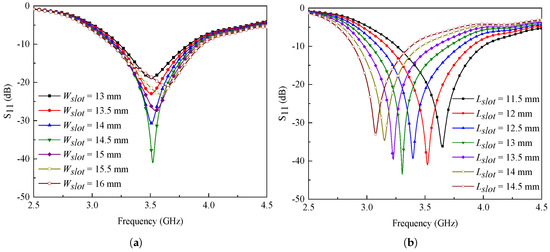
Figure 3.
Simulated characteristics for various values of (a) and (b) .
Figure 3a illustrates the characteristics of the proposed antenna for varying values of parameter . It can be noted from the figure that the parameter has a significant effect on impedance matching. The maximum impedance matching is observed for = 14.5 mm, as shown in Figure 3a. On the other hand, when the value of parameter is changed in the range from 11.5 mm to 14.5 mm, a shift in the resonant frequency is observed, as shown in Figure 3b. It is important to mention here that these values have a negligible effect on the isolation performance of MIMO antennas.
2.2. Characteristics of Proposed MIMO Antenna
The simulated S-parameters of the proposed MIMO antenna are shown in Figure 4. From Figure 4, it is observed that the designed MIMO antenna is resonating well for the band of interest, i.e., 3.5 GHz. Furthermore, the minimum isolation between adjacent antenna elements is noted to be >10 dB. A variation is observed in the response, which mainly occurred due to feeding points and different placements of antenna elements on the smartphone PCB, as shown in Figure 1. In addition to this, the mainboard is rectangular in nature, which could cause some discrepancies in the frequency response and couplings, mainly between even and odd port numbers. However, one can adjust the desired frequency band by modifying design parameters explained in Figure 3 [20].
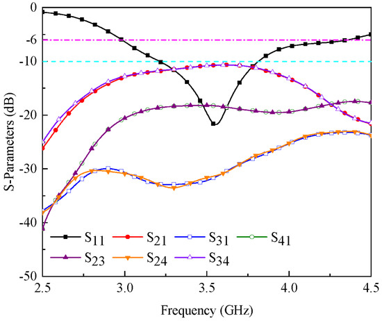
Figure 4.
Simulated S-parameters of the proposed sub-6 GHz MIMO antenna.
The designed antenna’s simulated three-dimensional (3-D) gain patterns are presented in Figure 5. The antenna generates different vertical and horizontal polarized radiation patterns for the chosen frequency band, as shown in the diagram. In addition, as demonstrated in Figure 5, the antenna has a gain of ∼3.6 dBi. The resulting radiation patterns further confirm that the MIMO antenna adheres to pattern diversity, which is a desirable feature for future smartphone applications.
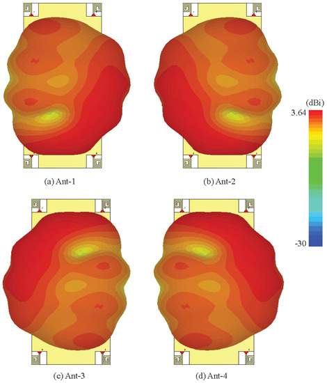
Figure 5.
Three-dimensional gain patterns of the proposed sub-6 GHz MIMO antenna.
One of the most critical aspects in determining the performance of MIMO antennas is the ECC. For practical applications, the ECC should be <0.5 and, ideally, it is ≈0. The ECC can be determined by using the S-parameters of the MIMO system as [21]:
where and are reflection coefficients, while and are MIMO antenna transmission coefficients.
As shown in Figure 6a, the value of ECC for the intended frequency band (3.5 GHz) is <0.01. The results also demonstrate high isolation between antenna elements, which is a crucial factor for simultaneous operation. The DG of the suggested MIMO antenna, on the other hand, can be calculated as follows [22]:
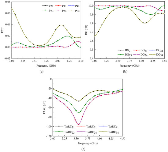
Figure 6.
Simulated (a) ECC, (b) DG, and (c) TARC results of the proposed sub-6 GHz MIMO antenna.
For the presented MIMO antenna, the DG value is noted to be >9.9 dB, as shown in Figure 6b.
The total active reflection coefficient (TARC) is another significant metric to consider while evaluating the MIMO antenna’s performance and can be evaluated as follows [23]:
The results demonstrate that the suggested MIMO antenna delivers TARC >20 dB for the band of interest, as illustrated in Figure 6c.
2.3. Fabrication and Measurements
A fabricated prototype of the proposed MIMO antenna is illustrated in the inset of Figure 7 along with the feeding mechanism. A prototype was fabricated using an LPKF-D104 milling machine and evaluated with an Agilent Precision Network Analyzer (PNA-E8363C). A flexible, semi-rigid RF cable is used for the feeding purpose. One end of the cable is connected to the antenna, while the second end is connected to a coaxial connector. Due to the similar performance and placement of the antenna elements, only port-1 and port-2 are measured and compared.
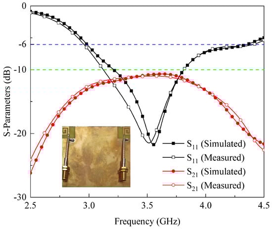
Figure 7.
S-parameters of adjacent antenna elements (inset of the figure shows fabricated sub-6 GHz MIMO antenna along with the feeding mechanism).
A comparison between simulated and measured S-parameters is depicted in Figure 7. A reasonable agreement is observed between simulated and measured and . The simulated −6 dB and −10 dB impedance bandwidths are noted to be 1.38 GHz (2.98–4.36 GHz) and 620 MHz (3.2–3.82 GHz), respectively, while the measured bandwidths are 1.45 GHz (2.96–4.41 GHz) and 680 MHz (3.13–3.81 GHz), respectively. Besides this, the isolation between antenna elements is >10 dB (see Figure 7) at the desired frequency band.
The simulated and measured ECC and TARC results are illustrated in Figure 8. It is observed that the simulated and measured data comply with each other. The ECC value for the band of interest is <0.08, as shown in Figure 8a. Aside from that, the TARC value for the operating band is 20 dB, as shown in Figure 8b.
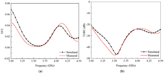
Figure 8.
Simulated and measured (a) ECC and (b) TARC of adjacent antenna elements.
The simulated and measured realized gain for port-1 is shown in Figure 9a. The gain is measured by exciting port-1, while port-2 is terminated using a 50 matched load. The average simulated and measured realized gain at port-1 is noted to be 4 dBi (see Figure 9a). The simulated realized gain varies in the range from 2 to 4.75 dBi, while the measured realized gain fluctuates in the range of 2.14–4.59 dBi, as shown in Figure 9a. The radiation and total efficiency results for port-1 are shown in Figure 9b. It is observed that the designed antenna has a radiation efficiency >90%, while the total efficiency fluctuates in the range of 70–95%. One thing that needs to be observed from Figure 9b that the designed antenna offers constant radiation efficiency in the band of interest.
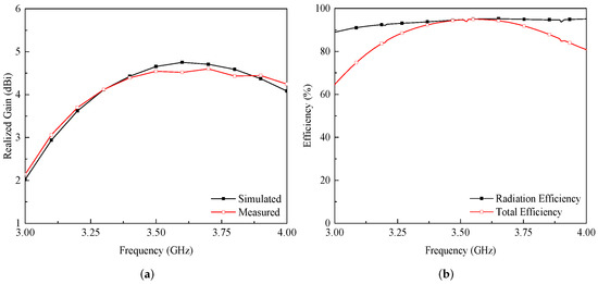
Figure 9.
(a) Simulated and measured realized gain, and (b) radiation and total efficiency of the proposed sub-6 GHz MIMO antenna when port-1 is excited.
The simulated and measured radiation characteristics for port-1 and port-2 for frequencies 3.2 GHz, 3.5 GHz, and 3.9 GHz are illustrated in Figure 10 and Figure 11. The designed MIMO antenna provides quasi-omnidirectional radiation characteristics for both - and -plane at the given frequencies. In addition, the MIMO antenna offers pattern diversity in the -plane, as seen in Figure 10 and Figure 11. Moreover, the measured results are well-matched with the simulated data for both planes.
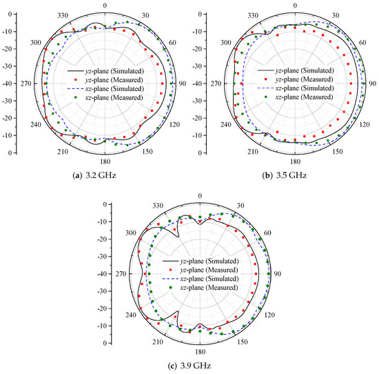
Figure 10.
Radiation characteristics of the proposed sub-6 GHz MIMO antenna when port-1 is excited.
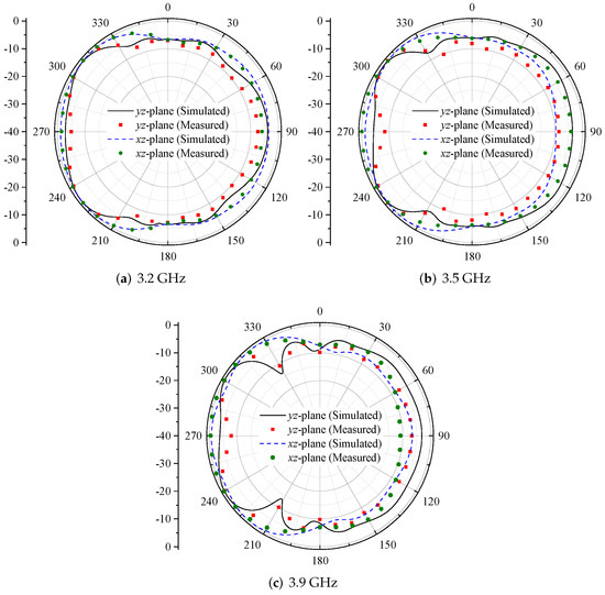
Figure 11.
Radiation characteristics of the proposed sub-6 GHz MIMO antenna when port-2 is excited.
2.4. User’s Impact on Antenna Characteristics
In this section, the user’s impact on MIMO antenna performance is examined. Performance is evaluated in terms of S-parameters and radiation efficiencies. The MIMO antenna performance is evaluated in the presence of the user’s single and double hand, as shown in Figure 12a,b.
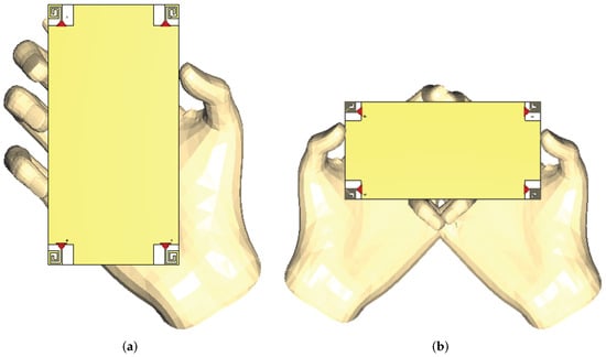
Figure 12.
MIMO array placement for (a) single-hand and (b) double-hand scenarios.
The developed MIMO antenna has appropriate reflection coefficients in the region of the human hands, as shown in Figure 13a,b. For the single-hand scenario, >10 dB of isolation is noted between the antenna elements, as shown in Figure 14a, while for double-hand mode, the isolation is >15 dB (see Figure 14b). Besides this, from Figure 15a,b, it can be noted that the efficiencies of antenna elements degraded. In case of single-handed operation, the reduction in radiation efficiency is noted for Ant-1 and Ant-3, whereas for the double-hand scenario, Ant-2 and Ant-3 provide less radiation efficiency. This is due to the features of human body tissue (fingers near the antenna), which can absorb a lot of antenna radiation power [24]. On the whole, the proposed MIMO antenna offers radiation efficiencies in the range of 39–68% for both scenarios for the desired frequency band.
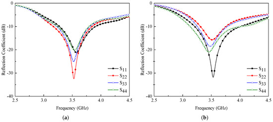
Figure 13.
Reflection coefficients of the proposed MIMO antenna in case of (a) single-hand and (b) double-hand scenarios.
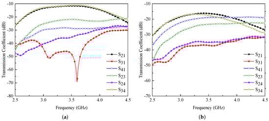
Figure 14.
Transmission coefficients of the proposed MIMO antenna in case of (a) single-hand and (b) double-hand scenarios.
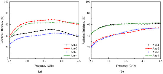
Figure 15.
Radiation efficiency of the proposed MIMO antenna in case of (a) single-hand and (b) double-hand scenarios.
For antennas used in mobile phone applications, one of the most important considerations is the specific absorption rate (SAR) [13,25]. The SAR is a parameter that measures the amount of electromagnetic waves that are absorbed by the human body [26]. The SAR characteristics with user-head are explored and displayed in Figure 16. The minimum SAR is noted to be 0.94 W/Kg for Ant-2, while the maximum SAR value is 2 W/Kg for Ant-3. It is noted that the closer the elements are to the head phantom, the higher the SAR value, and vice versa.
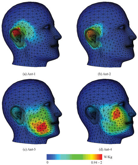
Figure 16.
SAR analysis when MIMO antenna used in talk-mode.
A comparison of previously reported and designed sub-6 GHz MIMO antennas is given in Table 2. One can observe from the table that the electrical dimensions of the single antenna element are small compared with the designs of [7,8,12,13]. The design presented in [11] offer high gain and low ECC, but due to their non-planar configuration, they can rarely be used in handheld devices. On the other hand, the planar antennas designed in [7,12,13,18] offer high isolation within their operational bandwidth, but they offer low antenna efficiency. Therefore, it can be concluded from Table 2 that the proposed MIMO antenna offers high radiation efficiency, acceptable gain, and low ECC even with a lower number of elements.
Table 2.
Comparison of proposed and previously reported sub-6 GHz MIMO antennas.
3. Conclusions
A uni-planar MIMO antenna design is presented for sub-6 GHz 5G-enabled mobile phone applications. Four loop-shaped radiators are designed at each corner of a smartphone board, and they all follow the design configuration of pattern diversity. Several MIMO antenna features are evaluated, such as S-parameters, gain patterns, radiation and total efficiency, ECC, TARC, and DG. From the reported results, it may be concluded that the presented MIMO antenna system successfully meets the criteria of 5G-enabled mobile phones.
Author Contributions
Conceptualization, U.R. and S.K.; methodology, U.R., S.K. and S.M.A.; software, U.R., S.K. and S.H.K.; validation, U.R., S.H.K., S.M.A. and S.I.S.; formal analysis, U.R., M.M.A., S.M.A., S.I.S. and M.D.; investigation, U.R., M.M.A., S.H.K., S.M.A. and M.A.; resources, S.H.K., S.I.S., M.A. and M.D.; writing—original draft preparation, U.R. and S.K.; writing—review and editing, M.M.A., S.H.K., S.M.A. and S.I.S.; visualization, U.R.; supervision, M.M.A. and S.M.A.; project administration, M.M.A., M.A. and M.D.; funding acquisition, M.A. and M.D. All authors have read and agreed to the published version of the manuscript.
Funding
This project has received funding from Universidad Carlos III de Madrid and the European Union’s Horizon 2020 research and innovation programme under the Marie Sklodowska-Curie Grant 801538.
Institutional Review Board Statement
Not applicable.
Informed Consent Statement
Not applicable.
Data Availability Statement
Not applicable.
Acknowledgments
The authors sincerely appreciate the support from Universidad Carlos III de Madrid and the European Union’s Horizon 2020 research and innovation programme under the Marie Sklodowska-Curie Grant 801538.
Conflicts of Interest
The authors declare no conflict of interest.
References
- Osseiran, A.; Boccardi, F.; Braun, V.; Kusume, K.; Marsch, P.; Maternia, M.; Queseth, O.; Schellmann, M.; Schotten, H.; Taoka, H.; et al. Scenarios for 5G mobile and wireless communications: The vision of the METIS project. IEEE Commun. Mag. 2014, 52, 26–35. [Google Scholar] [CrossRef]
- Kammoun, A.; Debbah, M.; Alouini, M.S. Design of 5G full dimension massive MIMO systems. IEEE Trans. Commun. 2017, 66, 726–740. [Google Scholar]
- Yang, H.H.; Quek, T.Q. Massive MIMO Meets Small Cell; Springer: Berlin/Heidelberg, Germany, 2017. [Google Scholar]
- Ojaroudi Parchin, N.; Jahanbakhsh Basherlou, H.; Al-Yasir, Y.I.; Abd-Alhameed, R.A.; Abdulkhaleq, A.M.; Noras, J.M. Recent developments of reconfigurable antennas for current and future wireless communication systems. Electronics 2019, 8, 128. [Google Scholar] [CrossRef] [Green Version]
- Andrews, J.G.; Buzzi, S.; Choi, W.; Hanly, S.V.; Lozano, A.; Soong, A.C.; Zhang, J.C. What will 5G be? IEEE J. Sel. Areas Commun. 2014, 32, 1065–1082. [Google Scholar] [CrossRef]
- Parchin, N.O.; Al-Yasir, Y.I.A.; Abd-Alhameed, R.A. Microwave/RF Components for 5G Front-End Systems; Avid Science: Hyderabad, India, 2019. [Google Scholar]
- Li, Y.; Luo, Y.; Yang, G. High-isolation 3.5 GHz eight-antenna MIMO array using balanced open-slot antenna element for 5G smartphones. IEEE Trans. Antennas Propag. 2019, 67, 3820–3830. [Google Scholar] [CrossRef]
- Ullah, R.; Ullah, S.; Ullah, R.; Faisal, F.; Mabrouk, I.B.; Al Hasan, M.J. A 10-Ports MIMO Antenna System for 5G Smart-Phone Applications. IEEE Access 2020, 8, 218477–218488. [Google Scholar] [CrossRef]
- Zhang, X.; Li, Y.; Wang, W.; Shen, W. Ultra-wideband 8-port MIMO antenna array for 5G metal-frame smartphones. IEEE Access 2019, 7, 72273–72282. [Google Scholar] [CrossRef]
- Abdullah, M.; Kiani, S.H.; Iqbal, A. Eight element multiple-input multiple-output (MIMO) antenna for 5G mobile applications. IEEE Access 2019, 7, 134488–134495. [Google Scholar] [CrossRef]
- Jiang, W.; Liu, B.; Cui, Y.; Hu, W. High-isolation eight-element MIMO array for 5G smartphone applications. IEEE Access 2019, 7, 34104–34112. [Google Scholar] [CrossRef]
- Ojaroudi Parchin, N.; Jahanbakhsh Basherlou, H.; Alibakhshikenari, M.; Ojaroudi Parchin, Y.; Al-Yasir, Y.I.; Abd-Alhameed, R.A.; Limiti, E. Mobile-phone antenna array with diamond-ring slot elements for 5G massive MIMO systems. Electronics 2019, 8, 521. [Google Scholar] [CrossRef] [Green Version]
- Parchin, N.O.; Al-Yasir, Y.I.; Basherlou, H.J.; Abd-Alhameed, R.A.; Noras, J.M. Orthogonally dual-polarised MIMO antenna array with pattern diversity for use in 5G smartphones. IET Microw. Antennas Propag. 2020, 14, 457–467. [Google Scholar] [CrossRef]
- Kiani, S.H.; Altaf, A.; Abdullah, M.; Muhammad, F.; Shoaib, N.; Anjum, M.R.; Damaševičius, R.; Blažauskas, T. Eight element side edged framed MIMO antenna array for future 5G smart phones. Micromachines 2020, 11, 956. [Google Scholar] [CrossRef] [PubMed]
- Iffat Naqvi, S.; Hussain, N.; Iqbal, A.; Rahman, M.; Forsat, M.; Mirjavadi, S.S.; Amin, Y. Integrated LTE and Millimeter-Wave 5G MIMO Antenna System for 4G/5G Wireless Terminals. Sensors 2020, 20, 3926. [Google Scholar] [CrossRef] [PubMed]
- Parchin, N.O.; Basherlou, H.J.; Al-Yasir, Y.I.; Abd-Alhameed, R.A. A broadband multiple-input multiple-output loop antenna array for 5G cellular communications. AEU-Int. J. Electron. Commun. 2020, 127, 153476. [Google Scholar] [CrossRef]
- Parchin, N.O.; Al-Yasir, Y.I.; Abdulkhaleq, A.M.; Basherlou, H.J.; Ullah, A.; Abd-Alhameed, R.A. A New broadband MIMO antenna system for sub 6 GHz 5G cellular Communications. In Proceedings of the 2020 14th European Conference on Antennas and Propagation (EuCAP), Copenhagen, Denmark, 15–20 March 2020; pp. 1–4. [Google Scholar]
- Ojaroudi Parchin, N.; Jahanbakhsh Basherlou, H.; Al-Yasir, Y.I.; Abdulkhaleq, A.M.; Patwary, M.; Abd-Alhameed, R.A. A new CPW-Fed diversity antenna for MIMO 5G smartphones. Electronics 2020, 9, 261. [Google Scholar] [CrossRef] [Green Version]
- Ahmad, U.; Ullah, S.; Rafique, U.; Choi, D.Y.; Ullah, R.; Kamal, B.; Ahmad, A. MIMO Antenna System With Pattern Diversity for Sub-6 GHz Mobile Phone Applications. IEEE Access 2021, 9, 149240–149249. [Google Scholar] [CrossRef]
- AI-Yasir, Y.I.; Parchin, N.O.; Alabdullah, A.; Mshwat, W.; Ullah, A.; Abd-Alhameed, R. New pattern reconfigurable circular disk antenna using two PIN diodes for WiMax/WiFi (IEEE 802.11a) applications. In Proceedings of the 2019 16th International Conference on Synthesis, Modeling, Analysis and Simulation Methods and Applications to Circuit Design (SMACD), Lausanne, Switzerland, 15–18 July 2019; pp. 53–56. [Google Scholar]
- Mazloum, J.; Ghorashi, S.A.; Ojaroudi, M.; Ojaroudi, N. Compact Triple-Band S-Shaped Monopole Diversity Antenna for MIMO Applications. Appl. Comput. Electromagn. Soc. J. 2015, 30, 975–980. [Google Scholar]
- Kumar, A.; Ansari, A.Q.; Kanaujia, B.K.; Kishor, J. High isolation compact four-port MIMO antenna loaded with CSRR for multiband applications. Frequenz 2018, 72, 415–427. [Google Scholar] [CrossRef]
- Sharawi, M.S. Printed multi-band MIMO antenna systems and their performance metrics [wireless corner]. IEEE Antennas Propag. Mag. 2013, 55, 218–232. [Google Scholar] [CrossRef]
- Stuchly, M. Electromagnetic fields and health. IEEE Potentials 1993, 12, 34–39. [Google Scholar] [CrossRef]
- Ojaroudiparchin, N.; Shen, M.; Zhang, S.; Pedersen, G.F. A switchable 3-D-coverage-phased array antenna package for 5G mobile terminals. IEEE Antennas Wirel. Propag. Lett. 2016, 15, 1747–1750. [Google Scholar] [CrossRef] [Green Version]
- Moustafa, J.; McEwan, N.; Abd-Alhameed, R.; Excell, P. Low SAR phased antenna array for mobile handsets. Appl. Comput. Electromagn. Soc. J. 2006, 21, 196. [Google Scholar]
Publisher’s Note: MDPI stays neutral with regard to jurisdictional claims in published maps and institutional affiliations. |
© 2022 by the authors. Licensee MDPI, Basel, Switzerland. This article is an open access article distributed under the terms and conditions of the Creative Commons Attribution (CC BY) license (https://creativecommons.org/licenses/by/4.0/).