Abstract
Robots equipped with anchoring mechanisms have attractive applications in asteroid exploration. However, complex application scenarios bring great challenges to the modeling and control of anchoring mechanisms. This paper presents a grasping model and control method for an anchoring mechanism for asteroid exploration. First, the structure of the anchoring mechanism is demonstrated. Second, stochastic grasping models based on surface properties are established. The effectiveness of the grasping model is verified by experiments. A stiffness-modeling method of the microspine is proposed. On this basis, the stochastic grasping model of the anchoring mechanism is established, and the grasping cloud diagram of the anchoring mechanism is drawn. Third, in order to reduce the collision force between the anchor mechanism and the asteroid surface, a control method for the anchoring mechanism in the movement process is proposed based on the motion mode of the asteroid-exploration robot. Finally, a prototype is developed, and the experimental results validate the motion ability of the robot and the control method.
1. Introduction
In recent years, researchers have become increasingly interested in small solar system objects [1,2]. Satellites equipped with advanced equipment, such as thermal imaging, are used to observe the physical properties of objects at close range [3,4,5,6]. These scientific missions focus on observing physical information, such as heat distribution, composition, and revolution of the asteroid surface. At present, the Hayabusa, Hayabusa2, and OSIRIS-REx probes have successfully collected asteroid samples [7,8,9,10]. Due to the microgravity environment of small celestial bodies, few researchers explore the mobile robots moving on their surfaces. The traditional wheeled rover cannot travel easily in the microgravity environment [11]. The Minerva detector mounted on Hayabusa2 abandons the traditional mode of motion [12]. As a jump system, a flywheel is installed in the Minerva detector. The inertial reaction generated by driving the flywheel makes the detector jump [13]. The design of the jump system has proven to be successful. However, it poses great challenges in predicting the position and time after hopping. Legged robots are widely considered to have excellent movement ability and can cross irregular terrain, such as slopes and gravel piles. Compared with a wheeled rover, a legged robot can cross obstacles longer than the fuselage by adjusting its gait. However, the small collision force between its limbs and the asteroid surface is enough to push the asteroid robot into space [14]. In the face of complex situations, the anchoring mechanism is necessary to assist the asteroid robot to firmly grasp the asteroid surface to resist the interference of unstable factors to the asteroid robot.
In order to realize the movement of legged robots on the surface of asteroids, researchers have proposed several kinds of anchoring mechanisms. Parness presented an anchoring foot mechanism for moving on an asteroid [15,16,17,18,19]. This mechanism had two degrees of freedom. One was used to control the lifting and lowering of the carriage. The other was used to tighten cables to pull microspines in the carriage to grasp the rough surface. Chacin presented a six-legged asteroid surface robot for exploring asteroids [20]. A steel nail was installed at the end of each leg [21]. Any five of the six legs formed a gripper when they were in contact with the ground. Another asteroid-exploration robot proposed by Chacin was equipped with three grippers that recognized millimeter features [20]. The gripper was covered with small steel nails, and they could grasp the brick and rock surface. Throughout their research, these researchers focused on designing a mechanism to assist the asteroid robot to maintain its grip on the asteroid surface. However, there is little research on the modeling and grasping process of the anchoring mechanism or gripper. For the anchoring mechanism, its function is to firmly grasp the surface of the asteroid. Therefore, it is necessary to further study the grasping mechanism of the anchoring mechanism.
Many asteroids have a regolith layer on their surface, which is the result of collisions on the asteroid surface over tens of thousands of years [22,23,24,25]. Pores of different sizes are distributed on its surface, which can be used as the anchor point of the robot. Obviously, a microspine is suitable for grasping these tiny pores. Microspines are widely used in various grippers [26,27,28,29]. Pope put forward a small robot crawling on the wall of the building, which established the grasping model of the microspine [30]. Based on the adhesion model of the microspine, the motion of the robot was planned. As mentioned above, the robot presented by Parness could grasp rough surfaces through hundreds of microspines. The microspine technology is also applied to mountaineering tools to assist people to stand [31]. The microspine array contains multiple microspines. The movement of each microspine does not affect the others. Even if one of the microspines captures the asperity, other microspines still have the opportunity to grasp asperities when continuously pulling the microspine array. Therefore, determining the stiffness of the microspine and the microspine array is the basis of establishing the grasping model. Asbeck first defined nine elements in the microspine stiffness matrix [32,33]. The microspine stiffness matrix for a crawling robot was directly given. However, there is no specific stiffness model in the paper. Jiang put forward a grasping model based on the microspine, and measured the stiffness of the microspine by experimental method [34]. The elastic microspine can still be stretched after adhesion, so its stiffness model is an important factor to determine adhesion. Therefore, Jiang developed an accurate stiffness model of the microspine and combined it with the grasping model of the microspine array.
Okada and Trigo-Rodríguez made detailed observations on the surface of Ryugu and comet [35,36]. The surfaces of asteroids may be covered with boulders, craters, and other landforms, while comets may be covered with rough and porous materials. These pores are usually fragile. Therefore, the adhesion of the anchoring mechanism should be controllable in order to grasp the pores without damaging them. Backus tested the adhesion of the anchor mechanism for asteroid exploration, and proposed a method for the desorption of the anchor mechanism [37]. Chacin proposed a motion control method based on a hexapod robot [20,38]. Limbs reacted to the friction under various conditions, and force closure conditions of robot motion were established. The mission of asteroid-exploration robots is not only to land on asteroids, but also to move and sample on asteroids. The role of the anchoring mechanism in the movement of the asteroid-exploration robot should be focused. The anchoring mechanism mainly undertakes two tasks. When the asteroid-exploration robot moves, the anchoring mechanism grasping the ground should provide stable and sufficient adhesion to prevent the robot from flying into space. At the same time, the anchoring mechanism mounted on the swing phase leg should quickly establish adhesion to ensure the stability of the asteroid-exploration robot. Obviously, the motion of the asteroid-exploration robot needs to be further studied.
Considering the application of the microspine in the anchoring mechanism, this paper proposes grasping models for the microspine array and a control method for the anchoring mechanism. The article is arranged as follows: Section 2 describes the structure and working principle of the anchoring mechanism. Section 3 establishes stochastic models for grasping. Then the stiffness model of the microspine is established. The grasping cloud diagram of the anchoring mechanism is drawn. Section 4 analyzes potential problems in the movement of the asteroid-exploration robot, and the collision avoidance control method of anchoring mechanism in the movement is proposed. In Section 5, a walking experiment of the prototype is carried out, and the experimental results are analyzed. Section 6 is the conclusion.
2. Anchoring Mechanism
The asteroid robot can safely land on and locomote on the asteroid with the anchoring mechanism. The configuration of the anchoring mechanisms and the robot are shown in Figure 1a–c. The anchoring mechanism is mounted on the end of the leg through a spherical hinge. The spherical hinge ensures the anchoring mechanism has appropriate passive compliance. When the robot locomotes in an unknown environment, the spherical joint can quickly adapt to the terrain to grasp the surface of the asteroid. As the only power source, the servo motor is installed on the shell of the anchoring mechanism. The driving torque is transmitted to the drive disc through the rack and pinion. Inelastic cables (not shown) passing through the holes of the anchor mechanism base connect the edge of the drive disc to the base of the microspine arrays. The base of the microspine array ensures that all the microspines are dragged the same distance on the surface of the asteroid. The steel needle fixed at the bottom of the microspine conforms to the millimeter-scale asperity. The special configuration of the microspine ensures it has appropriate flexibility in the tensile direction. The flexibility gives all microspines the opportunity to engage with asperities. The independent microspine can still travel on the asteroid surface after its adjacent microspines engaged to asperities.
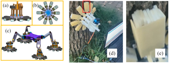
Figure 1.
3D model and prototype of the anchoring mechanism. (a,b) are front and bottom views of the anchoring mechanism; (c) 3D model of asteroid exploration robot; (d) The anchoring mechanism grabs the trunk (e) The microspine array grabs the trunk.
Driving the servo motor to rotate drives the rack to move up in a straight line along the positioning rod, and the drive disc fixed at the end of the rack performs the same movement. The rising of the drive disc pulls the cables, thereby dragging all the microspine arrays to retract towards the center of the anchor mechanism. The reverse rotation of the servo motor drives the rack and the drive plate fixed on the rack to move downward. As the cable tension decreases, it gradually approaches the return force of the spring compressed in the previous process. When the tension reaches the critical value, the base of the microspine array is pushed away from the center of the anchoring mechanism under the action of the return force of the recovery spring. When the deformation is zero, that is, when the microspine array returns to its initial state, the microspine is separated from the asteroid surface.
In order to intuitively show the characteristics of the microspine array, an experiment on the anchoring mechanism was carried out, as shown in Figure 1d,e. Before the anchoring mechanism grasps the trunk, an external force acts on the microspine array of the anchoring mechanism. For the microspine array, appropriate positive pressure helps it grasp the rough surface. Because the radius of the curvature of the trunk is small, only two or three microspine arrays directly above and below can grasp the trunk. Steel needles of other microspine arrays cannot contact the trunk because of interference. Take the microspine array in the red rectangle as an example. When the microspine array is pulled the same distance, some of the microspines are engaged to the trunk earlier, such as the four on the left. The fifth and sixth microspine on the left are engaged to the trunk later. As can be seen from Figure 1e, the second and third microspines on the right are not engaged to the trunk. This is precisely because of the independence of the microspine, that is, the travel of the microspine is not interfered with by other microspines, and all microspines have the opportunity to engage with asperities.
3. Stochastic Models for Grasping
3.1. Surface Properties
The surface properties are among the factors affecting the maximum adhesion that the anchoring mechanism can provide. Obviously, the microspine array can more easily engage with a rough surface. On smooth surfaces, such as glass, the microspine array has difficulty providing stable adhesion. The influence of surface properties on the microspine is discussed below.
There are two surface properties that determine whether the microspines can grasp the surface: the spatial distribution of asperities and the angle of asperities. The spatial distribution of asperities affects the possibility of microspine-asperity engagement. More asperities per unit length makes it more likely for the microspine to engage when it contacts the surface, and the microspine travels a shorter distance along the surface to engage. Asbeck has studied the relationship between the tangential force and angle [33]. In this section, we discuss the spatial distribution of asperities in more detail. Assuming that asperities are randomly distributed on the surface, we can model the appearance of asperities as a random process. Therefore, the distance between adjacent asperities is described by random distance, and the number of asperities per unit distance is certain. It also shows that the microspine starts to travel in the gap of two asperities on the surface, and the longer the distance the microspine travels before catching the next asperity, the greater the probability of engagement. For the shape-modeling of asperities, a more intuitive triangle model is applied instead of the semicircle model used in the Hertz contact model, because the relationship between the probability of engagement and the travel distance is more worthy of attention, rather than the magnitude or direction of the contact force. The two-dimensional model of asperities is shown in Figure 2.
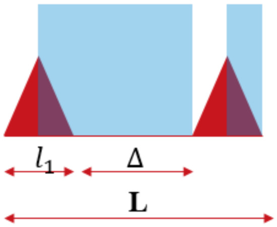
Figure 2.
Two-dimensional model of asperities.
The red triangles in Figure 2 are asperities, the length of the asperity is , the length of adjacent asperities is , and the distance between them is . If the loading angle is appropriate, the microspine will not disengage under the tension after catching an asperity, rather than travel on the surface. That is to say, when the microspine contacts the surface, it cannot engage immediately when it is located in the area with a blue background (non-ideal region). It needs to travel a certain distance on the surface under the tension to engage. Therefore, there are only two cases when the microspine contacts with the surface: when it engages with an asperity, and when it is located in a non-ideal region. It is a binomial distribution, and the probability of engagement can be expressed as:
If a microspine is located in a non-ideal region, the probability that it will be located at any point in the region is the same. The probability is related to the number of discrete points in the non-ideal region. It is obvious that if the microspine located in the non-ideal region is closer to the previous asperity, it needs to travel a longer distance to catch the next asperity. The distance that the microspine travels in the non-ideal region is related to its position. The discrete model of the non-ideal region is shown in Figure 3.
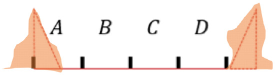
Figure 3.
The discrete model of the non-ideal region.
The non-ideal region is divided into four parts equally, and the length of each part is called the step size. If the microspine travels one step on the surface, all the points in the D region can catch the next asperity, while the points in other regions still stay in the non-ideal region. If the microspine travels three steps, only points in the A region cannot engage, but points in the C and D regions only need to travel two and one step, respectively, to engage. Considering the interval distance between adjacent asperities and the size of asperities, the process of the microspine traveling on the surface can be modeled as Poisson distribution:
where is the mathematical expectation of the number of asperities grasped by the microspine traveling on the surface, is the number of asperities engaged with the microspine, and is the distance the microspine travels on the surface to grasp an asperity. So far, the probability of the engagement with an asperity immediately and the probability of the engagement with an asperity after traveling in the non-ideal region have been derived. Then, the probability of the microspine grasping an asperity in the process of traveling on the surface is as follows:
Figure 4 intuitively shows the influences of ground parameters and on grasping probability. Figure 4a shows that affects the probability that the microspine will engages once it touches the surface. Figure 4b shows that the starting points of the three curves are different, and the more asperities on the ground, the greater the grasping probability.
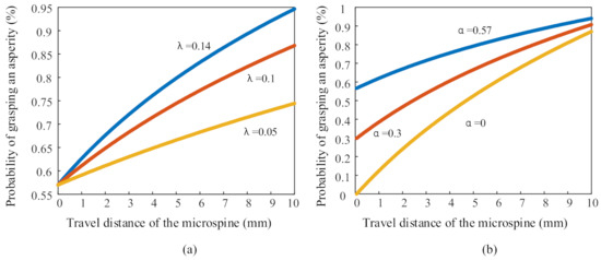
Figure 4.
Influence of surface properties on grasping probability.
The experiment was carried out on two samples with microspines in random positions. During the movement, the distance between the starting point and the first rough surface meshed with the microspore is measured by caliper. The microspine is pulled until it desorbs or reaches the limit tension 3 N. The experimental results are shown in Figure 5. Every circle in Figure 5 represents the results of 200 experiments. It can be seen from the figure that the adhesion probability of the microspine on brick is significantly higher than that on sandpaper. The experimental results on two materials are in good agreement with the prediction curve (red curve). It should be noted that the strength of the surface is not considered among the surface properties. After many experiments, we found that asperities of the surface are unlikely to be damaged by microspines.
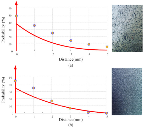
Figure 5.
Experimental results and prediction curves. (a) The microspine travels on the surface of the brick, , . (b) the microspine travels on sandpaper, , .
3.2. Adhesion Model Based on Desorption
As mentioned by Asbeck, in addition to the spatial distribution of asperities, the contact strength also affects the strength of adhesion [33]. On the surface with low contact strength, the microspine has a greater chance of desorption from the surface. Through observation of the experimental process, it can be seen that with the increase in tension, the microspine can grasp the surface on the rough surface. For the sandpaper surface, with the increase in tension, the microspine desorbs and reengages many times.
The experiment was carried out by slowly pulling a microspine along a rough surface. After the microspine engaged to the asperity, the tension was continuously applied until the microspine desorbed or reached 6 N. Figure 6 shows the relationship between the tensile force and adhesion probability. For the surface of the brick, in most cases, the microspine could withstand a tensile force of 1.2 N. Thus, the probability curve was almost horizontal if the force was less than 1.2 N. With the increase in tension, the probability curve was no longer parallel to the x-axis, but could be approximately regarded as a first-order function. When the force was greater than 1.2 N, the grasping probability could be approximated by a straight line. For the surface of brick, the adhesion probability can be expressed by a piecewise function:
where is the slope of the first-order function, and is less than 0; is the intercept of the first-order function from the y-axis. The influence of tensile force on adhesion probability can be obtained by force probability curve. So far, the tangential adhesion of the microspine can be expressed as:
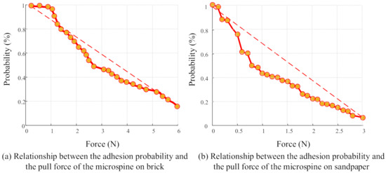
Figure 6.
Relationship between the pull force and the adhesion probability.
In practical application, the robot can scrape along the surface with its spine array foot equipped with instruments, so as to understand the surface-asperity distribution [34]. On a rough surface, the tangential force is a function of the pull and travel distance. The longer the travel distance, the more likely the microspine is to be engaged to asperities. However, the microspine may desorb after continuous application of tension. In the follow-up, the adhesion of the microspine will be studied in combination with the stiffness of the microspine.
3.3. Stiffness Model of the Microspine
The microspine can be regarded as a variant of a planar serpentine spring. A microspine consists of multiple identical units. They are arranged in order through a pattern connected end to end. Generally speaking, the microspine has a certain stiffness in the X and Y directions of its plane. The movement and rotation in Z direction are limited by adjacent microspines. The microspine with square structure is adopted in this paper. The microspine is divided into 10 parts. Since the base is located below the 10th, the deformation of this part is not considered. The unit number, load position and direction of the microspine are shown in Figure 7a. It is assumed that under the action of external force, the microspine produces only elastic deformation but no plastic deformation. According to Karnofsky’s second theorem, the deformation of ① can be expressed as:
where is the elastic model of the microspine, is the section moment of inertia of the microspine, is the length of ①, and is the cross-sectional area of the microspine. The deformation of ② can be obtained:
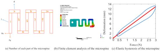
Figure 7.
Model and analysis of the microspine.
Considering that the configuration and size of each unit of the microspine are the same, the deformation of the microspine in the direction can be expressed as:
If the cross-sectional area of the microspine is expressed as and the cross-sectional moment of inertia is expressed as , then the stiffness of the microspine in the direction can be expressed as:
The stiffness of the rest of the microspine in the direction can be expressed as:
Similarly to calculating the deformation in the direction, the deformation of the microspine in the direction can be expressed as the superposition of multiple deformation of the same part:
The stiffness in the direction can be written as:
Based on the stiffness model and the stochastic model for grasping, the driving-force model of the anchoring mechanism can be expressed as:
where is the number if microspines, is the stiffness of the microspine, is the probability of a microspine engage with asperities, and is the lifting distance of drive disc.
For verifying the deduced stiffness model, the finite element software was used to simulate the deformation of the microspine caused by the force. In Figure 7b, the model is fixed on the left. Then the deformation of the microspine in the direction of the applied force was recorded. The parameters of the microspine are as follows: , , , , . The simulation results are shown in the figure below. A 1 N tangential force ( direction) is applied at the end of the microspine, and deformation of the microspine is . The stiffness is about . Compared with the result calculated by Equation (11), the error is 4.1%.
3.4. Grasping Model of the Anchoring Mechanism
Whether due to the asteroid robot’s leg stepping action, adjustment of the posture of the fuselage, or a disturbance, there is an external force acting on the anchoring mechanism that grasps the asteroid surface. Previous studies have focused on the analysis of the grasping model of a single microspine. In this section, the grasping model of the centrosymmetric anchoring mechanism is established.
The microspine array is pulled by a cable that behaves similarly to animal’s tendon. The cable converts the lifting force of the drive disk into tension and acts on the microspine array. Because there is no energy consumption due to deformation, the inextensible cable improves the pulling efficiency.
Before discussing the influence of external force on the anchoring mechanism, opposed-direction microspines are modeled here. After two opposite microspines are engaged to the asperities, the external force will cause the microspine on one side to provide a greater shear force, while the microspine on the opposite side tends to break away from the asperity.
For comprehensively evaluating the grasping force of the anchoring mechanism, an experiment was carried out. The maximum rotation angle of the driving servo motor of the anchoring mechanism was 35°, and the experiment was carried out every 5°. The angle between the vector of the external force and the vector of the surface ranged from 0° to 90°, and the experiment was carried out every 10°. In order to ensure the validity of the experimental data, 100 groups of experiments were carried out for each permutation and combination. The experimental results are shown in Figure 8. The maximum adhesion of the anchoring mechanism continued to decrease as the direction of the external force deviated from the direction of the normal vector of the ground. This phenomenon was particularly obvious at the maximum rotation angle of the driving motor. This showed that the ability of the anchoring mechanism to resist the external force in the horizontal direction was weak. When planning the motion of the robot, the excessive external force acting on the horizontal direction of the anchoring mechanism should be avoided.
Figure 8.
Cloud diagram of grasping capacity of anchoring mechanism. X. Y, Z, respectively, represent the angle of the driving motor of the anchoring mechanism (°), the included angle between the direction vector of the external force and the direction vector of the ground (°), and the maximum force that the anchoring mechanism can bear (N).
3.5. Preload
We found that in practical application, the anchoring mechanism was difficult to separate from the rough surface, even without pulling the microspine array. This was because when the microspine array traveled a distance of 0 mm on a rough surface, the microspine still had the opportunity to engage with the asperity on the surface. There were more than 300 microspines on each anchoring mechanism. Placed on a surface with an initial meshing probability of 10%, there were theoretically more than 30 microspines engaged with asperities. These microspines may have been oriented in different directions, resulting in a high probability that the anchoring mechanism would grasp the rough surface without pulling the microspine arrays. This explains why when the angle of the servo motor in Figure 8 was 0, the anchor mechanism still received an external force of 8 N before it desorbed.
On the basis of not changing the structure of the anchoring mechanism, we adopted the preloading strategy. That is, we pulled the microspine array before the anchoring mechanism contacted the asteroid surface. Under the action of tension, the recovery spring was compressed. After the anchoring mechanism released the ground, the recovery spring pushed the microspine array to the initial position. It increased the probability of desorption of the anchoring mechanism.
However, preloading presents new challenges. For improving the efficiency of the driving force of the anchoring mechanism, the stiffness of the recovery spring should be as low as possible. ENot much energy is stored in the recovery spring. If the stiffness of the recovery spring is too low, it cannot push the microspine array back to the initial position. Experiments were conducted by pulling a microspine array with 10 pieces of the microspine on a block surface. The stiffness of the microspine was . It was pulled until reaching the limited force or the limited distance after being preloaded to . A force sensor was used to measure the load.
Figure 9 illustrates the effects of springs with different stiffnesses on the pulling of the microspine array on a rough surface. The series connection of the recovery spring with lower stiffness and the microspine array brought the mechanism closer to the constant force spring. This series mode can still provide stable adhesion on weak surfaces. On a strong surface, the shear force from the microspine array overcomes the elastic force of the recovery spring, and finally it reaches the maximum shear force. Through the analysis of spring stiffness and its application on different rough surfaces, the low-stiffness recovery spring is considered to be the preferred scheme.
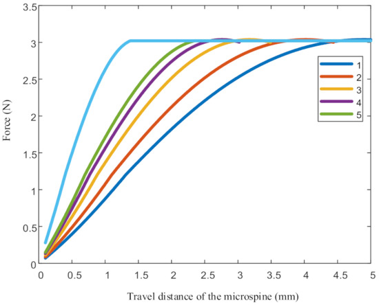
Figure 9.
Relationship between stiffness and displacement of different recovery springs. The stiffness of 1 to 5 in the figure is 1.5, 2, 3, 4 and 5 (N/mm) respectively.
4. Control of the Asteroid Robot
The engagement of a single microspine with surface roughness is point contact. Thus, the grasping of the anchoring mechanism can be regarded as a collection of multiple point contacts. Ideally, the planes of the microspines’ steel needles are parallel to the asteroid’s surface. This ensures that all microspines have the same opportunity to engage with roughness. For the safety of the asteroid-exploration robot, the anchoring mechanism should provide stable adhesion.
The escape velocity of small bodies can be lower than 10 cm/s, and therefore the asteroid robot usually locomotes at a relatively slow speed. At the same time, it is also necessary to reduce the external force on the robot to prevent it from jettisoning itself into space. Compared with dynamic gait, the static gait obviously meets the above conditions. The asteroid robot maintains at least three anchoring mechanisms to grasp the surface of the asteroid all the time. Three anchoring mechanisms form stable fulcrums to prevent the reaction from affecting the balance of the robot. Although the angle of the anchor mechanism cannot be controlled, the spherical hinge and the spring damping system connecting the anchor mechanism and the leg give the anchoring mechanism the ability to reposition. Because the anchoring mechanism is symmetrical, the existence of passive joints reduces two rotational degrees of freedom, which mitigates the load of knee joint servo motor. Without compliance control, the anchoring mechanism with accurately controlled angle is likely to collide with the surface of asteroids without accurate angle information. Compliance control also reduces the risk of the robot flying into space. Nevertheless, passive joints did not reduce this potential risk. After the robot’s leg stepped forward one step, the included angle between the anchoring mechanism and the surface changed. In order to show this process more intuitively, the simulation of the asteroid robot is shown in Figure 10. The red line in the figure indicates the position of the ball joint in the Z direction. When the leg was in the beginning of swing phase, the included angle between the leg and the anchor mechanism did not change under the influence of the spring damping system. In the late swing phase, the anchoring mechanism collided with the ground. With the movement of the spherical hinge, the anchoring mechanism gradually approached the ground until the spherical hinge reaches the target position. Obviously, taking the spherical joint as the end of the asteroid robot’s leg to plan the path will lead to a violent collision between the anchoring mechanism and the asteroid surface. Due to the existence of passive joints, this collision is inevitable. Therefore, the planning of spherical joints should meet the following two requirements:
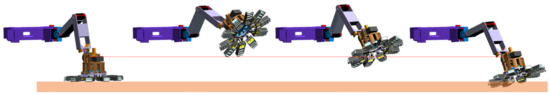
Figure 10.
The motion process of the anchoring mechanism when stepping.
- (1)
- The collision between the anchoring mechanism and the ground should be as small as possible to reduce the impact force from the asteroid surface when the leg is in the swing phase;
- (2)
- The anchoring mechanism should quickly approach the asteroid surface and grasp it, so as to improve the stability of the robot.
In order to discuss the collision between the anchoring mechanism and the ground, the anchoring mechanism was selected as a research object. The coordinates of the spherical joint relative to the fuselage can be recorded as: . The coordinates of each microspine array relative to the fuselage are obtained through the geometric relationship with the spherical joint, which can be recorded as:
where is the diameter of the bottom circle of the circular platform; is the height of the dome; is the angle between the th microspine array and the positive direction of the anchoring mechanism. The joint angle of the leg is obtained by bringing into the inverse solution model of the asteroid robot. The length of the leg and joint angles are brought into the transfer matrix to obtain the coordinates of all microspine under the knee joint:
The coordinates of the microspine array relative to the fuselage can be obtained by bringing the coordinates of the microspine array relative to the knee joint into the positive solution model of the robot. In this way, the real-time position of the microspine array in the swing phase can be obtained. Then, when the microspine array is in contact with the surface of the asteroid, the position of the spherical hinge and all microspine arrays relative to the fuselage are also determined. Taking the direction as the forward direction of the asteroid robot, the leg trajectory can be regarded as a stepping forward of the robot’s front leg. Suppose that at moment , a microspine array of the anchoring mechanism is in contact with the surface of the asteroid. In order to make the anchoring mechanism close to the ground at the fastest speed, the path of the spherical joint should be re-planned.
It is assumed that there is only static friction between the anchoring mechanism and the asteroid surface. That is, the microspine array, which first came into contact with the asteroid surface, is engaged to asperities. When an arc is drawn with the contact point as the center and the distance from the contact point to the opposite microspine array as the radius, the direction of the unit vector of the connecting line between the end point of the arc and the center of the circle is parallel to the asteroid surface:
where is the distance from the microspine array to the spherical joint, is the bending stiffness of the spring at the ball joint, and is the included angle between the anchoring mechanism and the asteroid surface, which depends on the posture of the leg before walking. It is worth noting that the direction of compensation is the opposite direction of the step leg. That is to say, when the robot moves forward, the sign of the compensation for the front leg is negative and the sign of the compensation for the rear leg is positive.
5. Generalized Control Algorithm
The walking of the asteroid robot can be regarded as a cyclic process. The general closed-loop control system is used to control the attitude adjustment of the fuselage and the swing phase of the legs of the asteroid robot. The closed-loop control system includes an event trigger, which is used to identify whether the anchoring mechanism collides with the asteroid surface. The event trigger sends the trigger signal to the path adjustment controller, which is a sub controller of the closed-loop controller. After receiving the trigger signal, the path adjustment controller will optimize the path of the foot end and send it to the path-planning module. The control algorithm of asteroid exploration robot is shown in Figure 11.
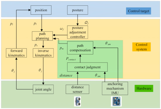
Figure 11.
Control algorithm of asteroid-exploration robot.
Considering the speed and attitude requirements of the asteroid robot, the motion planning and control algorithm includes the following modules:
- (1)
- Closed-loop control
The expected position of the asteroid and the attitude of the fuselage are sent to the closed-loop control system as the inputs of the closed-loop control system. The posture adjustment controller calculates the desired angular velocities of the fuselage, and they are sent to the path-planning module together with the desired velocity of the legs. The path-planning module sends the discrete foot end position to the inverse solution module, and then joints receive joint angles calculated by the inverse solution module. After the joints of the asteroid robot are driven, the joint angles are sent to the forward kinematics model. The position of the end of the leg is obtained through forward kinematics, and it is sent to the control target.
- (2)
- Path-planning module
The function of the path-planning module is to plan the position of the spherical joint installed at the end of the leg, and send three-dimensional coordinates to the controller for the inverse kinematics solution. This module has three inputs: the target position of the spherical joint, the attitude of the fuselage and the compensation amount of the spherical joint path. Before the anchoring mechanism contacts the asteroid surface, only the target position of the spherical joint and the fuselage attitude are used as inputs.
- (3)
- Contact-judgment module
There are two methods to determine the contact point between the anchoring mechanism and the asteroid surface. First, the terrain of asteroids can be obtained by depth camera. According to the forward kinematics model of the asteroid robot, the position of the anchoring mechanism in the control cycle can be obtained. Then the compensation is designed in the path planning to optimally guide the motion of the asteroid robot. In the second method, the contact force is detected by the force sensor installed on the anchoring mechanism and sent to the controller, and the position of the contact point is calculated according to the angle of the leg joint and the positive solution model. The force signal is used to judge whether the anchoring mechanism is in contact with the asteroid surface. However, too many microspines make it difficult to detect the collision force between the anchoring mechanism and the asteroid surface. In this paper, the distance sensor signal was used to judge whether there was a collision. The distance sensor was installed in the center of the drive disc. Through the angle information of the anchoring mechanism and the distance information between the anchoring mechanism and the asteroid surface, we could judge whether the anchoring mechanism collided with the asteroid surface.
- (4)
- Path-compensation module
The path-compensation module calculates the compensation amount of the end of the leg according to the contact position and the angle of the anchoring mechanism, and sends it to the path-planning module. The path-planning module adds the compensation and the initial path together, and sends it to the inverse-kinematics module as a new path.
The difference between this algorithm and the traditional robot-control algorithm is that the event trigger and foot-position compensation module are added to the closed-loop control system. Without this module, the end of the leg moves according to the established trajectory under closed-loop control, while the anchoring mechanism collides violently with the asteroid surface. Violent collisions should be avoided in the motion control of the asteroid robot. They not only affect the stability of the robot, but may also lead to damage of the anchoring mechanism. The traditional impedance control or feedback control cannot easily solve this problem, while this algorithm can well compensate the end of the leg after the anchoring mechanism contacts the asteroid surface.
6. Experiments
For evaluating the performance of the anchoring mechanism and the effectiveness of the control strategy when the asteroid-exploration robot walks, a walking experiment was carried out. The asteroid robot was arranged to walk on the site built in the laboratory. The experimental process is shown in Figure 12. The four pictures in each line represent the states when the robot walks. From top to bottom, these show: swinging the left front leg, swinging the right front leg, moving the fuselage forward, swinging the left rear leg, and swinging the right rear leg. In general, the asteroid-exploration robot walked smoothly. Before each leg lift, the anchor mechanism released the ground. After the leg completed the swing phase, the anchoring mechanism gripped the ground again.
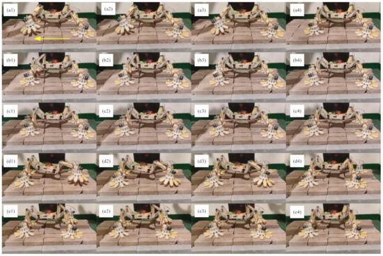
Figure 12.
Walking experiment of asteroid-exploration robot.
It is assumed that the asteroid-exploration robot’s direction of locomotion is the Y direction, and the Z direction points to the ground. Pitch angles of the anchor mechanism installed on the left front leg and the left rear leg are shown in Figure 13. The figure records the pitch angle of the anchor mechanism during five steps. The red curve represents the pitch angle of the anchoring mechanism without the control algorithm. The blue curve represents the pitch angle of the anchoring mechanism under the control algorithm proposed in this paper. Since the rotation direction of the ball joints of the front and rear legs is opposite, the pitch angle of the anchoring mechanism in Figure 13b is negative. It can be seen from the figure that with each step, the trend of the first half of the red curve and the blue curve is similar. The anchoring mechanism fails to completely separate from the ground when lifting the leg, and the inclination of the robot body is the main reason for the slight difference in the first half of curves. The contact between the microspine array and the surface occurs about 7.26 s after stepping. The blue curve drops first, which means that the control algorithm begins to work. As the anchoring mechanism begins to grasp the asperities of the ground, it gradually approaches the ground until the anchoring is completed. However, without a control strategy, the anchoring mechanism will crush the surface. It can be seen from the red curve in the figure that the angle of the anchoring mechanism does not decrease, but gradually increases. This situation is the same as the simulation result shown in Figure 10. Under the impact force, the anchoring mechanism finally hits the surface.
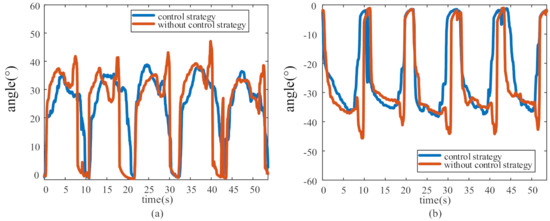
Figure 13.
Pitch angle of anchoring mechanism of left legs. (a) and (b) represent the pitch angles of the anchoring mechanism installed on the left front leg and the left rear leg, respectively.
7. Conclusions
In this paper, a spatial distribution model of asteroid surface asperities and stochastic grasping models of the microspine based on asteroid surface parameters and tensile force are established. The prediction effect of the microspine grasping model on different surfaces is verified by experiments. Through a large number of experiments, the grasping cloud diagram of the anchoring mechanism is drawn. The stiffness of the recovery spring is optimized, and a collision-avoidance strategy for the anchoring mechanism of an asteroid robot is proposed. Through the walking experiment of the prototype of the asteroid robot, the effectiveness of the algorithm and the performance of the prototype are verified.
Author Contributions
Q.W. was in charge of the trial; Q.W. and J.H. wrote the manuscript; F.G. assisted with analyses. All authors have read and agreed to the published version of the manuscript.
Funding
Supported by the National Natural Science Foundation of China under Grant 52175022, the Major Project of Science and Technology Innovation 2030 under Grant 2018AAA0102700, the State Key Laboratory of Mechanical System and Vibration under Grant MSVZD202106, the Key Laboratory Fund of Science and Technology on Space Intelligent Control under Grant HTKJ2019KL502011, Shanghai R&D public service platform project under Grant 19DZ2291400.
Institutional Review Board Statement
Not applicable.
Informed Consent Statement
Not applicable.
Data Availability Statement
The study did not report any data.
Conflicts of Interest
The authors declare no conflict of interest.
References
- Trilling, D.E.; Lisse, C.; Cruikshank, D.P.; Emery, J.P.; Fernández, Y.; Fletcher, L.N.; Hamilton, D.P.; Hammel, H.B.; Harris, A.W.; Mueller, M.; et al. Spitzer’s Solar System studies of asteroids, planets and the zodiacal cloud. Nat. Astron. 2020, 4, 940–946. [Google Scholar] [CrossRef]
- Evans, N.W.; Tabachnik, S.A. Asteroids in the inner Solar system—II. Observable properties. Mon. Not. R Astron. Soc. 2000, 319, 80–94. [Google Scholar] [CrossRef] [Green Version]
- Warren, P.H. Lunar Meteorites and the Global Abundance of Pan (Purest Anorthosite): Inconvenient Truths about Remote Sensing for Planet-Surface Composition. Meteorit Planet Sci. 2018, 53, 6033. [Google Scholar]
- Filacchione, G.; Capaccioni, F.; Ciarniello, M.; Raponi, A.; Tosi, F.; De Sanctis, M.C.; Erard, S.; Morvan, D.B.; Leyrat, C.; Arnold, G.; et al. The global surface composition of 67P/CG nucleus by Rosetta/VIRTIS. (I) Prelanding mission phase. Icarus 2016, 274, 334–349. [Google Scholar] [CrossRef] [Green Version]
- Warren, P.H. “New” lunar meteorites: Implications for composition of the global lunar surface, lunar crust, and the bulk Moon. Meteorit. Planet. Sci. 2005, 40, 477–506. [Google Scholar] [CrossRef]
- Masterson, R.A.; Chodas, M.; Bayley, L.; Allen, B.; Hong, J.; Biswas, P.; McMenamin, C.; Stout, K.; Bokhour, E.; Bralower, H.; et al. Regolith X-Ray Imaging Spectrometer (REXIS) Aboard the OSIRIS-REx Asteroid Sample Return Mission. Space Sci. Rev. 2018, 214, 48. [Google Scholar] [CrossRef]
- Nakamura, T.; Noguchi, T.; Tanaka, M.; Zolensky, M.E.; Kimura, M.; Tsuchiyama, A.; Nakato, A.; Ogami, T.; Ishida, H.; Uesugi, M.; et al. Itokawa Dust Particles: A Direct Link Between S-Type Asteroids and Ordinary Chondrites. Science 2011, 333, 1113–1116. [Google Scholar] [CrossRef]
- Kawaguchi, J.; Fujiwara, A.; Uesugi, T. Hayabusa—Its technology and science accomplishment summary and Hayabusa-2. Acta Astronaut. 2008, 62, 639–647. [Google Scholar] [CrossRef]
- Beshore, E.; Sutter, B.; Mink, R.; Lauretta, D.; Moreau, M.; Boynton, W.; Dworkin, J.; Everett, D.; Shinohara, C.; Gal-Edd, J. The OSIRIS-REx Asteroid Sample Return Mission. In Proceedings of the 2013 IEEE Aerospace Conference, Big Sky, MT, USA; 2013. [Google Scholar]
- Gal-Edd, J.; Cheuvront, A. The OSIRIS-REx Asteroid Sample Return Mission Operations Design. In Proceedings of the 2013 IEEE Aerospace Conference, Big Sky, MT, USA; 2013. [Google Scholar]
- Uckert, K.; Parness, A.; Chanover, N.; Eshelman, E.J.; Abcouwer, N.; Nash, J.; Detry, R.; Fuller, C.; Voelz, D.; Hull, R.; et al. Investigating Habitability with an Integrated Rock-Climbing Robot and Astrobiology Instrument Suite. Astrobiology 2020, 20, 1427–1449. [Google Scholar] [CrossRef]
- Ulamec, S.; Kucherenko, V.; Biele, J.; Bogatchev, A.; Makurin, A.; Matrossov, S. Hopper concepts for small body landers. Adv. Space Res. 2011, 47, 428–439. [Google Scholar] [CrossRef]
- Ho, T.-M.; Baturkin, V.; Grimm, C.; Grundmann, J.T.; Hobbie, C.F.; Ksenik, E.; Lange, C.; Sasaki, K.; Schlotterer, M.; Talapina, M.; et al. MASCOT—The Mobile Asteroid Surface Scout Onboard the Hayabusa2 Mission. Space Sci. Rev. 2016, 208, 339–374. [Google Scholar] [CrossRef]
- Zhang, R.X.; Latombe, J.C. Capuchin: A Free-Climbing Robot Invited Paper. Int. J. Adv. Robot Syst. 2013, 10, 1–18. [Google Scholar] [CrossRef]
- Parness, A. Anchoring Foot Mechanisms for Sampling and Mobility in Microgravity. In Proceedings of the 2011 IEEE International Conference on Robotics and Automation (Icra), Shanghai, China, 9–13 May 2011. [Google Scholar]
- Parness, A.; Frost, M.; Wiltsie, N.; King, J.P.; Thatte, N.; Witkoe, K.; Nevarez, M.; Aghazarian, H.; Garrett, M.; Kennedy, B. Gravity Independent Climbing Robot: Technology Demonstration and Mission Scenario Development. In Proceedings of the AIAA Space 2013 Conference and Exposition, San Diego, CA, USA, 10–12 September 2013; p. 8. [Google Scholar]
- Parness, A.; Frost, M.; Wiltsie, N.; King, J.P.; Thatte, N.; Witkoe, K.; Nevarez, M.; Aghazarian, H.; Garrett, M.; Kennedy, B. Demonstrations of Gravity-Independent Mobility and Drilling on Natural Rock Using Microspines. In Proceedings of the 2012 IEEE International Conference on Robotics and Automation (Icra), Paul, MI, USA, 14–18 May 2012; pp. 3547–3548. [Google Scholar]
- Parness, A.; Willig, A.; Berg, A.; Shekels, M.; Arutyunov, V.; Dandino, C.; Kennedy, B. A Microspine Tool: Grabbing and Anchoring to Boulders on the Asteroid Redirect Mission. In Proceedings of the 2017 IEEE Aerospace Conference, Big Sky, MT, USA, 4–11 March 2017. [Google Scholar]
- Yoshida, K.; Maruki, T.; Yano, H.J.C.E.A. A novel strategy for asteroid exploration with a surface robot. Cospar. Entific. Assem. 2002, 34, 1961–1966. [Google Scholar]
- Chacin, M.; Yoshida, K. Stability and adaptability analysis for legged robots intended for asteroid exploration. In Proceedings of the 2006 IEEE/RSJ International Conference on Intelligent Robots and Systems, Beijing, China, 9–15 October 2006; p. 1744. [Google Scholar] [CrossRef]
- Chacin, M.; Yoshida, K. Evolving legged rovers for minor body exploration missions. P IEEE Ras. Embs. Int. 2006, 332, 170–175. [Google Scholar]
- Veverka, J.; Thomas, P.C.; Robinson, M.; Murchie, S.; Chapman, C.; Bell, M.; Harch, A.; Merline, W.J.; Bell, J.F.; Bussey, B.; et al. Imaging of Small-Scale Features on 433 Eros from NEAR: Evidence for a Complex Regolith. Science 2001, 292, 484–488. [Google Scholar] [CrossRef]
- Chapman, C.R. Stripped on passing by Earth. Nature 2010, 463, 305–306. [Google Scholar] [CrossRef]
- Tanbakouei, S.; Trigo-Rodríguez, J.M.; Sort, J.; Michel, P.; Blum, J.; Nakamura, T.; Williams, I. Mechanical properties of particles from the surface of asteroid 25143 Itokawa. Astron. Astrophys. 2019, 629, A119. [Google Scholar] [CrossRef] [Green Version]
- Trigo-Rodriguez, J.M. Asteroid Impact Risk: Impact Hazard from Asteroids and Comets; Springer Impact Studies Series; Springer: Cham, Switzerland, 2022. [Google Scholar]
- Wile, G.D.; Daltorio, K.A.; Diller, E.D.; Palmer, L.R.; Gorb, S.N.; Ritzmann, R.E.; Quinn, R.D. Screenbot: Walking Inverted Using Distributed Inward Gripping. In Proceedings of the 2008 IEEE/RSJ International Conference on Robots and Intelligent Systems, Conference Proceedings, Nice, France, 22–26 September 2008; p. 1513. [Google Scholar] [CrossRef]
- Wang, S.Q.; Jiang, H.; Cutkosky, M.R. Design and modeling of linearly-constrained compliant spines for human-scale locomotion on rocky surfaces. Int J. Robot Res. 2017, 36, 985. [Google Scholar] [CrossRef]
- Lynch, G.A.; Clark, J.E.; Lin, P.-C.; Koditschek, D.E. A bioinspired dynamical vertical climbing robot. Int. J. Robot. Res. 2012, 31, 974–996. [Google Scholar] [CrossRef]
- Galvez, J.A.; Estremera, J.; de Santos, P.G. A new legged-robot configuration for research in force distribution. Mechatronics 2003, 13, 907–932. [Google Scholar] [CrossRef]
- Pope, M.T.; Kimes, C.W.; Jiang, H.; Hawkes, E.W.; Estrada, M.A.; Kerst, C.F.; Roderick, W.R.T.; Han, A.K.; Christensen, D.L.; Cutkosky, M.R. A Multimodal Robot for Perching and Climbing on Vertical Outdoor Surfaces. IEEE Trans. Robot. 2016, 33, 38–48. [Google Scholar] [CrossRef]
- Wang, S.Q.; Jiang, H.; Huh, T.M.; Sun, D.; Ruotolo, W.; Miller, M.; Roderick, W.R.T.; Stuart, H.S.; Cutkosky, M.R. SpinyHand: Contact Load Sharing for a Human-Scale Climbing Robot. J. Mech. Robot Trans. ASME 2019, 11, 031009. [Google Scholar] [CrossRef] [Green Version]
- Asbeck, A.T.; Cutkosky, M.R. Designing Compliant Spine Mechanisms for Climbing. J. Mech. Robot Trans. ASME 2012, 4, 031007. [Google Scholar] [CrossRef] [Green Version]
- Asbeck, A.T.; Kim, S.; Cutkosky, M.R.; Provancher, W.R.; Lanzetta, M. Scaling Hard Vertical Surfaces with Compliant Microspine Arrays. Int. J. Robot. Res. 2006, 25, 1165–1179. [Google Scholar] [CrossRef] [Green Version]
- Jiang, H.; Wang, S.; Cutkosky, M.R. Stochastic models of compliant spine arrays for rough surface grasping. Int. J. Robot. Res. 2018, 37, 669–687. [Google Scholar] [CrossRef]
- Okada, T.; Fukuhara, T.; Tanaka, S.; Taguchi, M.; Arai, T.; Senshu, H.; Sakatani, N.; Shimaki, Y.; Demura, H.; Ogawa, Y.; et al. Highly porous nature of a primitive asteroid revealed by thermal imaging. Nature 2020, 579, 518–522. [Google Scholar] [CrossRef]
- Trigo-Rodríguez, J.M.; Llorca, J. The strength of cometary meteoroids: Clues to the structure and evolution of comets. Mon. Not. R. Astron. Soc. 2006, 372, 655–660. [Google Scholar] [CrossRef]
- Backus, S.B.; Onishi, R.; Bocklund, A.; Berg, A.; Contreras, E.D.; Parness, A. Design and testing of the JPL-Nautilus Gripper for deep-ocean geological sampling. J. Field Robot. 2020, 37, 972–986. [Google Scholar] [CrossRef]
- Chacin, M.; Mora, A.; Yoshida, K. Motion control of multi-limbed robots for asteroid exploration missions. IEEE Int. Conf. Robot. 2009, 1, 3037–3042. [Google Scholar]
Publisher’s Note: MDPI stays neutral with regard to jurisdictional claims in published maps and institutional affiliations. |
© 2022 by the authors. Licensee MDPI, Basel, Switzerland. This article is an open access article distributed under the terms and conditions of the Creative Commons Attribution (CC BY) license (https://creativecommons.org/licenses/by/4.0/).