Abstract
The automatic docking system of the loading and offloading arm of a tank car is the key link to realizing the unmanned operation of tank car loading and unloading. The spatial position detection of the flange port of a tank car can guide the automatic docking of the fluid loading and offloading arm and flange port of the tank car. In this paper, a flange position detection method based on image recognition was proposed. Firstly, the end state of the loading arm was analyzed to determine the expression mode of the loading arm’s spatial pose so as to form a unified expression with the flange position and docked pose on the tank car. Then, for the image processing of the flange port of the tank car, this paper binarized the edge of the flange end face based on the Otsu algorithm, used the Canny algorithm for edge detection, used the least squares method to fit the image edge coordinates into a spatial circle, calculated the center coordinates and normal vector of the flange end face, and used these parameters to guide the end of the loading arm to adjust the position and attitude so that it was consistent with the position and pose of the flange port to realize docking. Then, a circular object center detection and calibration experiment, a flange end face image experiment, and an automobile tank car flange port physical detection experiment were carried out. The test results show that the spatial coordinate accuracy of the flange port diameter and center detected by this method meets the requirements of the loading arm automatic docking system, providing a research idea for the design of an automatic docking system for the loading and unloading arm of a tank car.
1. Introduction
There are two ways to load tank cars: top loading and bottom loading. Top loading usually adopts a large loading and offloading arm (commonly known as a big crane tube), as shown in Figure 1. Bottom loading is usually loaded with a small loading and offloading arm (commonly known as a small crane tube), as shown in Figure 2. The two loading methods of top loading and bottom loading are suitable for the loading and offloading of different fluid media. Top loading is generally used for the loading and unloading of heavy oil. The upper loading and unloading arm is connected to the tank mouth of the tank car, which has a large diameter when the tank mouth is open. The docking is carried out manually. The staff pull the large loading and offloading arm to the tank mouth of the tank truck, extend the oil outlet of the large loading and offloading arm below the liquid level as far as possible, and keep an appropriate distance from the tank bottom of the tank truck. The tank car connected with the lower loading and unloading arm is closed without an open tank mouth. The loading and unloading liquid are connected with the external loading and unloading arm through the flange mouth at the tail of the tank car, and the loading and unloading arm is connected with the external pipeline to transport the liquid. The loading and offloading of oil and other liquids mostly adopts the top loading method, while the loading and offloading of liquefied natural gas mostly adopts the bottom loading method. The two loading and offloading methods of top loading and bottom loading exhibit significant differences in terms of automation control, interface form, sealing requirements, etc. [1]. This paper forms part of a project that aims to transform the automatic docking and unmanned operation of the loading and offloading arms of liquefied natural gas tank trucks. The main component of liquefied natural gas (LNG) is methane [2], which is recognized as the cleanest fossil fuel on earth. LNG is in a gaseous state at atmospheric temperature and pressure. Many vaporized volatiles are generated when using top loading [3]. Therefore, bottom loading is mainly used for the loading and unloading of low-temperature LNG and small crane tubes are often used for the loading and offloading of LNG in trucks. The typical connection between the offloading arm and the tanker when loading and offloading LNG is shown in Figure 2. The flange port for the docking of the loading and offloading arm is set at the bottom of the LNG tank, and the diameter of the outer diameter of the flange is 165 mm. There are rotary joints on the small crane tube. For docking, the small crane tube is dragged to make the rotary joint rotate left and right and up and down. The flange on the vertical pipe is connected to the flange on the tank trucks and then locked on with bolts.
Figure 1.
Tank car top loading.
Figure 2.
Tank car bottom loading.
This project studied the possibility of the automatic docking of the loading and offloading arm to replace the manual docking operation. The spatial position of the flange port of the tank truck is obtained by the method of visual image recognition. The integrated data processing program was used to calculate the normal vector and the circle center of the flange port. Then, the spatial position data of the flange port of the vehicle are transmitted to the automatic docking system of the loading and offloading arm, and the loading and offloading arm was driven by the actuator to realize automatic docking.
2. Research Status of Automatic Docking of Fluid Loading and Offloading Arms
Scholars and enterprises at home and abroad have carried out research related to the docking of fluid pipes, such as Wang’s automatic docking hose-type aerial refueling [4], which installs laser or infrared receiving devices at the oil pipe nozzles and refueling ports connected to an orientation controller. The electronic control system for automatic docking of marine loading and offloading arms invented by the No716 Research Institute of China Shipbuilding Industry Corporation uses a combination of various sensors and adopts the dual positioning mode to realize the automatic docking of marine loading and offloading arms [5]. Lianyungang Oceanic Fluid Handling Equipment Co., Ltd. has published a patent for an automatic docking system suitable for terminal oil handling arms and ship flanges [6]. It is mainly monitored in real time by a CCD camera to achieve precise docking of connectors and target flanges. The patent [7] of automatic alignment fluid loading and offloading arm and its control system applied by Lianyungang Hong Ze Machinery Equipment Co., Ltd. discloses a loading and offloading arm structure and automatic alignment system on a tank car. It can realize automatic identification and servo control of the loading and offloading arm and can also realize the remote operation of the fluid loading and offloading arm through human–computer interaction. From the research results disclosed above, it can be seen that, in the application cases in aviation, shipping, and land transportation, the focus is on the realization of the docking automation process, and the working efficiency of the automatic docking system is not high.
An automatic docking system for a small crane tube used in the lower part of a tank car has not been studied in the literature. The purpose of this project is to replace the manual operation with a system whose efficiency is higher than or at least the same as that of manual operation. The diameter of the blue port is much smaller than that of the marine loading and offloading arm interface and the tank port of the tank car, so its relative positioning accuracy needs to be high.
3. Implementation Plan and Theoretical Basis
The image recognition of the flange port in the automatic docking system is aimed at the flange port at the rear of the LNG tanker docked with the bottom loading and offloading arm using a sensor combined with an infrared camera [8], a 2D laser rangefinder [9], and millimeter wave radar [10]. Multiple categories of information are transmitted in parallel to intelligent instruments consisting of computers and microcontrollers. The flange port information is then analyzed and processed by the computer to extract the spatial position and direction of the flange port, which is provided to the controller of the automatic docking system of the loading and offloading arm, and the controller sends out instructions to drive the actuator of the loading and offloading arm to realize automatic docking. The block diagram of the working principle of the system is shown in Figure 3.
Figure 3.
Block diagram of the working principle of the system.
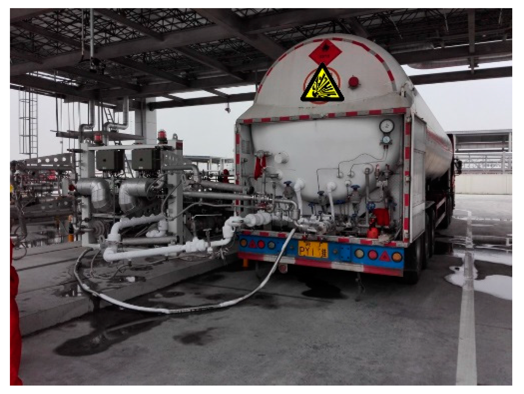
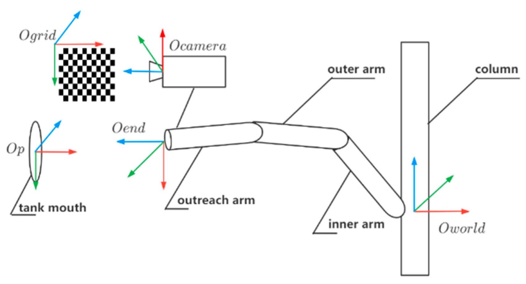
3.1. Loading and Offloading Arm Structure and Pose State
The structure of the bottom loading and offloading arm (small crane tube) is shown in Figure 4. The pipeline of the equipment is connected to the column by connecting pieces, and the upper and lower tubes are, respectively, the gas phase tube and the liquid phase tube; that is, it has a so-called dual-phase structure [11]. The loading and offloading arm is composed of a column, an inner arm, an outer arm, an outrigger arm, a connecting flange, and other components to form the main pipeline of the equipment. The outer arm is equipped with a spring cylinder balance device and is organically connected by five rotary joints to realize the 3D movement of the outrigger arm. This ensures the correct horizontal butt with the tanker flange at any position within the envelope.
Figure 4.
Structure diagram of loading and offloading arm.
We simplified the model for the outrigger nozzle of the small crane tube to a cylinder as shown in Figure 5. The port of the small crane tube in any state can be uniquely represented by a six-dimensional vector , where , and are the center point of the nozzle end face in the calibration frame coordinate system (the actual position in the measurement coordinate system), and are the inclination angles of the axis of the small crane tube projected in the and planes, respectively, and is the rotation angle of the end face of the small crane tube with the central axis as the rotation axis. During manual docking, the central axis of the outrigger of the small crane tube is adjusted to be level with the ground, that is, is 0. The state angles of the outrigger arm of the small crane are detected by the horizontal sensor and angle sensor on the loading and offloading arm, and the position coordinates of the center point of the nozzle end face are detected by the position sensor in the actuator.
Figure 5.
Diagram of small crane tube port pose.
The spatial coordinates and pose information of the docking between the flange port and the loading and offloading arm were obtained from the vision sensor and the distance sensor. Based on the spatial pose of the flange central axis, the spatial coordinates of the flange end face were calculated, and the small crane tube was leveled. Then, it completed the pose adjustment of the small crane tube through translational motion [12]. The details are as follows:
First, because the circular target appears as an ellipse after imaging, the actual position of the circle center in the image after perspective projection and the center position of the ellipse obtained by perspective projection of the circle outline often do not coincide. This error is called a perspective projection distortion error [13], so the contours to be selected in the image are screened by the least squares ellipse fitting method, and the space circle plane equation that can best represent the target is obtained;
Then, according to the data obtained by the sensor, take any point on the target space circle, calculate the plane equation tangent to the surface, and determine the normal vector of the plane in order to determine the space coordinates and pose of the target flange.
Finally, it calculates the coordinate of the fitting space plane along the Z-axis direction, and the value is the final depth position of the loading and offloading arm. The coordinates of the center of the target flange and the values of the angles are calculated. It measures and adjusts the position and attitude of the small crane tube so that the angles of the small crane tube and the angles of the target flange are matched to be equal so as to realize docking with the flange port.
3.2. Calibration Matrix Calculation
Image processing and stereo vision often involve four coordinate systems: world coordinate system, robot coordinate system, camera coordinate system, and image (pixel) coordinate system [14]. The image data of the target flange detected by the above sensors are all carried out in the image coordinate system. In order to realize the automatic docking of the loading and offloading arm, the coordinate points in the image coordinate system must be transformed into coordinate points in the world coordinate system. In this paper, the light principle was used to realize the reconstruction of 3D points from a single image; that is, the reconstruction of 3D points was realized by using the intersection of light rays and a known plane. In this paper, the Zhang calibration algorithm [15] was selected to calibrate the internal and external parameters of the camera in combination with the calibration plate. As shown in Figure 6, in one of the images used for calibration, the calibration plate was directly placed near the port of the small crane tube and the global coordinate system was established on the calibration plate.
Figure 6.
Calibration coordinate system transformation.
According to the principle of eye-to-hand, it is similar to the actual engineering, using the constant transformation relationship between the calibration plate and the loading and offloading arm:
where represents the homogeneous transformation matrix from the column to the end of the loading and offloading arm, represents the homogeneous transformation matrix from the end of the loading and offloading arm to the camera, represents the transformation matrix from the camera to the target, robot1 and robot2 represent the samples after the first and second movements of the loading and offloading arm, respectively, and the two samples were compared and calculated. We can rearrange the above formula to give
The obtained is the desired calibration matrix.
4. Flange Image Recognition Principle and Process
In the project, the vision sensor was used to take the image of the rear of the LNG tanker, the flange area was extracted from the rear image of the tanker, and the spatial position coordinates of the flange are thus established. Then, it passed the flange position parameter to the loading and offloading arm alignment mechanism and guided the loading and offloading arm to automatically align with the flange port. The specific process was as follows:
The first step was to binarize the image.
The binarized global threshold was obtained by the Otsu method [16]. The Otsu method, also known as the maximum inter-class variance method, divides the image into two parts, the background and the foreground, according to the grayscale characteristics of the image, and determines the image binarization segmentation threshold by the inter-class variance between the background and the foreground. The Otsu method is suitable for most occasions where the global threshold of the image is required. The most important thing is that the calculation is simple and fast and is not affected by the brightness and contrast of the image. At the same time, the experimental object is a single flange port, which is not affected by its shortcomings.
The second step is flange edge detection.
In an image, the edges are where the local intensity changes are most pronounced. The purpose of edge detection is to obtain the contour of the measured object from the background so as to further analyze the contour information of the measured object. In this paper, the Canny algorithm [17,18,19] was used to detect the edge. Compared with the ordinary gradient algorithm, the false edge caused by noise is greatly suppressed and the edge is thinned, which makes subsequent processing easier. The third step is to fit the space circle to determine the space pose of the flange port.
Find the circular target and perform spatial circle fitting through the three-dimensional data obtained by the interaction between the sensors to determine the spatial position and pose of the target flange.
4.1. Image Binarization and Edge Detection
Image acquisition is the first step in the visual inspection. Only when the information of the measured object is obtained is the collected image meaningful. The measured object in this paper is the flange port. According to the process of visual detection, after the image containing the target flange is collected the image needs to be processed. The Otsu method was used to determine the image binarization segmentation threshold, and the edge detection was performed after the binarization process. The purpose of edge detection was to obtain the contour of the target flange from the background through the Canny operator so as to further analyze the contour information of the target flange. For the original image data of the target flange obtained by the sensor, the redundant image information was filtered out after binarization, and then the edge information of the outer circle of the flange in the image is extracted to obtain the spatial circle coordinates of the target flange.
Generally, the calculation process of the Canny operator was divided into three steps: the first was to smooth and denoise the image with a Gaussian filter; second, the amplitude and direction of the gradient was calculated, and the non-maximum of the gradient amplitude was suppressed; third, the double threshold method was used to detect and connect the edges.
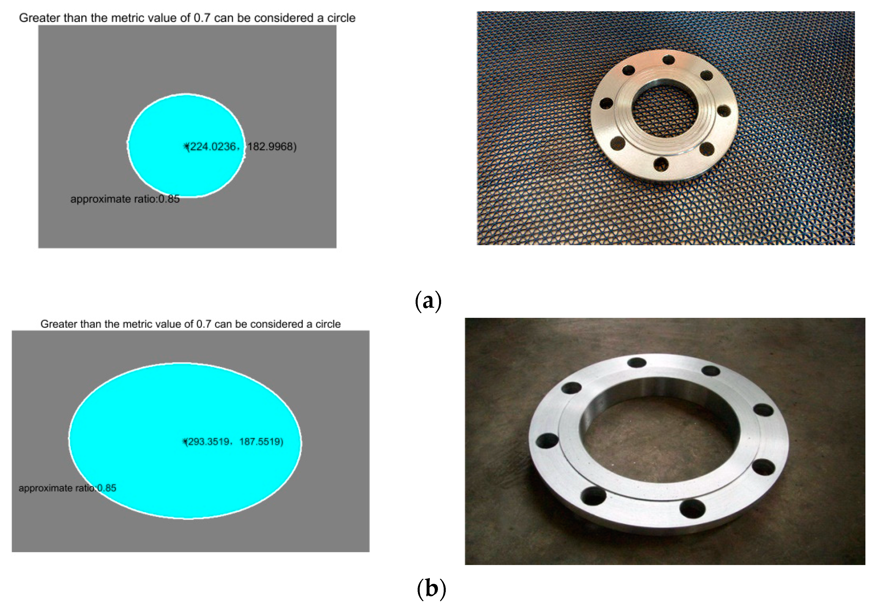
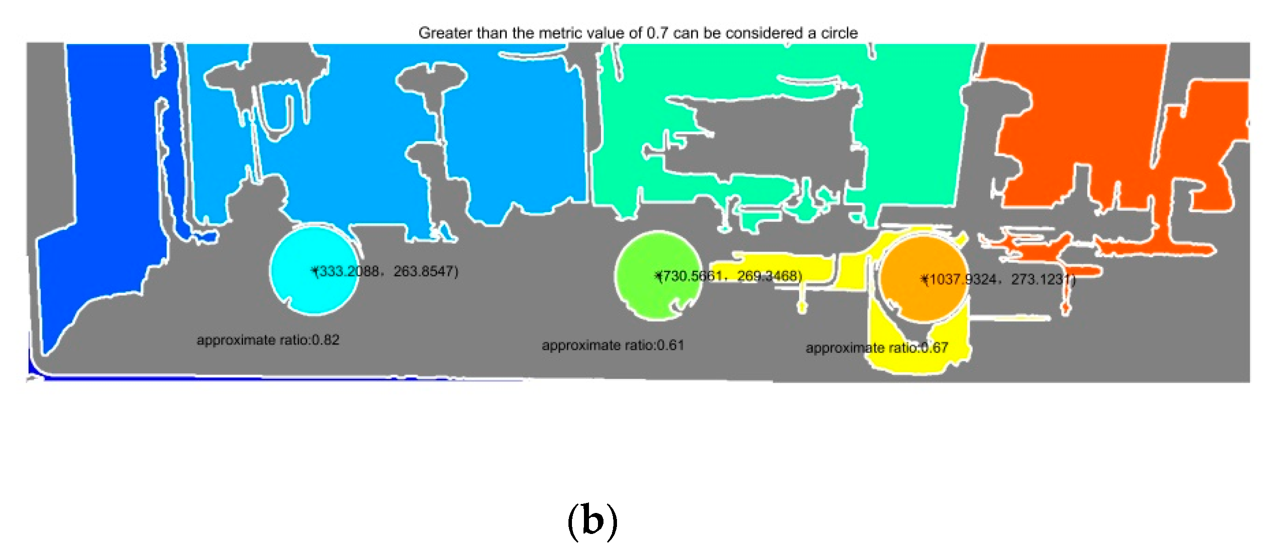
4.2. Spatial Circle Fitting and Circle Parameter Calculation
In the process of the automatic docking of the small crane tube, in order for the small crane tube to move to the specified space coordinates with a matching pose it is necessary to solve the problem according to the point cloud data of the target flange obtained by the sensor and obtain the pose of the target flange, including the space coordinates and the normal vector of the circle center.
Each point searches for its adjacent points and fits the adjacent points into a plane. Given the coordinates of discrete points in three-dimensional space , it constructs a space circle so that the space points are as close as possible to the fitted space circle.
First, all the discrete points are on a plane as far as possible; that is, the following conditions are met:
According to the least squares method, the plane normal vector can be obtained using Equation (5):
where:
Assuming that all discrete points are on the circle, the mid-perpendicular line connecting any two points must pass through the center of the circle.
As shown in Figure 7, the center of the circle takes two points . of the connecting vector is , the midpoint coordinate of the line connecting is , and the center of the connecting vector is . If are on the circle, then . Therefore:
Figure 7.
Schematic diagram of the principle of least squares.
If all points are on the circle, then:
where:
assuming that:
The above equation is an overdetermined equation and can be transformed into a well-posed form as:
Since the center c is on the plane of the circle:
Therefore, to solve the coordinates of the circle center, Equation (7) can be solved by constructing the optimization problem under the constraints of Equation (9). Therefore:
Then, the center coordinate C is:
The radius of the circle can be determined by the average of the distances from all points to center of the circle:
5. Experimental Process and Results Analysis
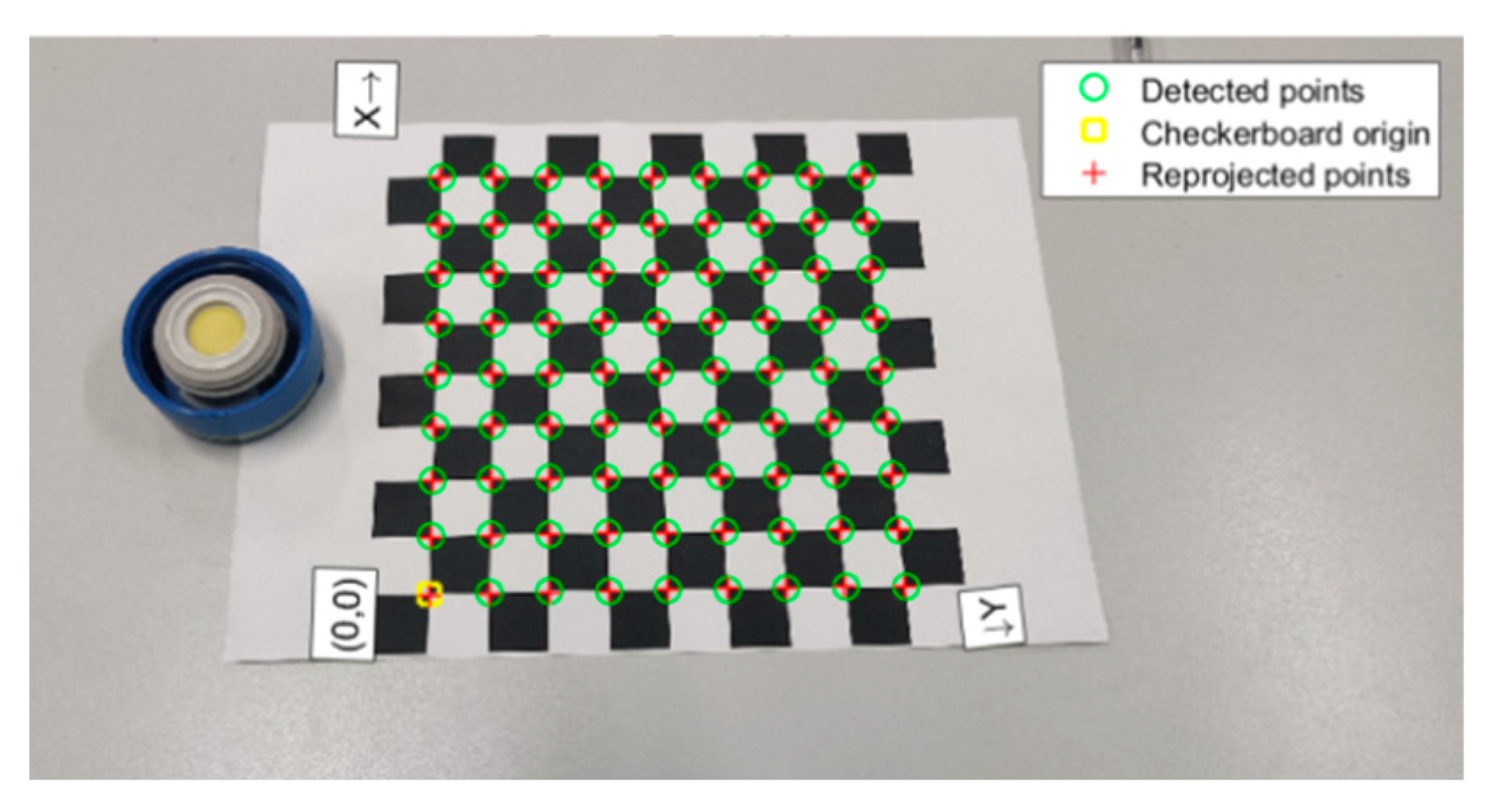
5.1. Calibration Experiment of Circle Center Detection
The system hardware of the calibration experiment is mainly composed of a camera, lens, calibration plate, disc, and data-processing platform. A camera with a SONY IMX586 photosensitive component as the main camera was used in this study. The resolution of this camera is 8000 × 6000 pixels. When the shooting distance of the camera relative to the target is 60 cm, the shooting vision of the camera is 50 cm× 20 cm, the resolution is 1824 × 4000, and the focal length is 4.76 mm. A computer with an i7-4750HQ CPU and 10GBRAM was used to process the experimental data.
The camera was used to capture the image as shown in Figure 8. Firstly, the Zhang You Zheng calibration algorithm was used to calibrate the internal and external parameters of the camera and then the simulated flange end face was detected based on the least squares method. The vertical direction and rotation of the object remain constant, and the radial distortion was [0.2815, −1.5715, 0] and tangential distortion was [0, 0, 0]. The experimental results of the target end face center are shown in Figure 9.
Figure 8.
Camera calibration.
Figure 9.
Detection experiment results of the center of the target end face.
On this basis, a calibrated camera is used to measure the end image of the target object. Figure 10 shows the absolute error diagram obtained using the above algorithm to locate and detect the center of the simulated flange target end face, which includes the absolute errors of the X-axis direction deviation distance and the Y-axis direction deviation distance relative to the standard image. After 81 experimental processes, a few maximum errors are removed and absolute error of X coordinate is ex = 0.97726 mm, and the absolute error of Y coordinate is ey = 1.09105 mm. In Figure 10, the X-axis represents the serial numbers of the 81 groups of circle centers. The two dot-line graphs represent the absolute error of the X and Y coordinates of the center of the circle, respectively, and each has a horizontal dashed line representing the respective error mean. Valid points are indicated by ‘o’, and error points are indicated by ‘+’. The accuracy of center positioning detection error meets the mechanical installation tolerance within the accuracy range of 3 mm. The experimental results show that this method can effectively improve the accuracy, efficiency and stability of the automatic docking system, improve the assembly consistency, and meet the requirements of automatic docking of a small crane tube.
Figure 10.
The circle center absolute error distribution curve along the X and Y axes.
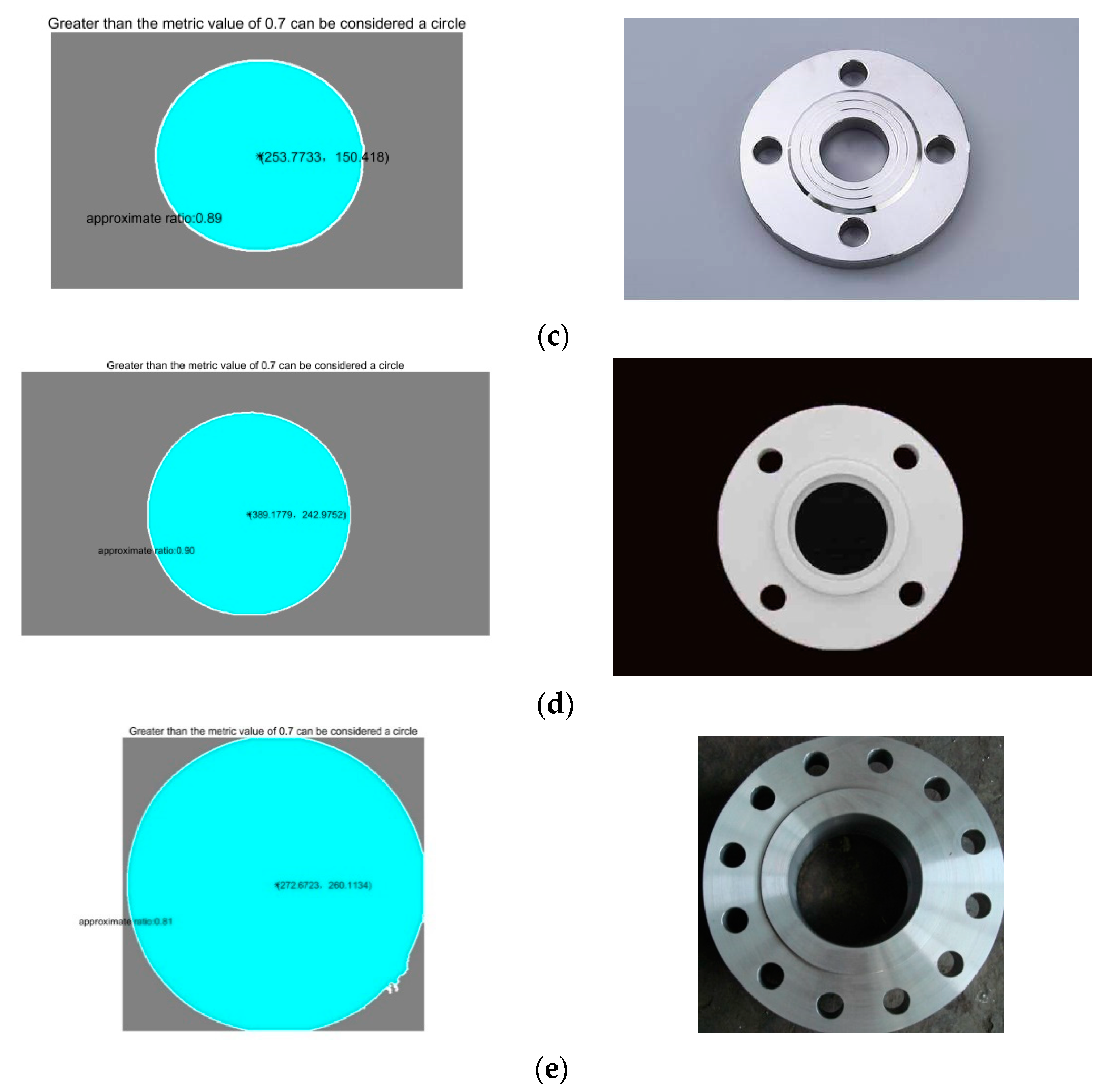
5.2. Detection Experiment of the Flange End Face Image
A group of flange end face images was used for our experiments, as shown in Figure 11. This image set contains five different flange images, which are, respectively, Figure 11a–e. Figure 11a represents the detection condition that is closest to the real working condition. Figure 11b represents the detection condition when the flange deviation angle is large. Figure 11c represents the detection condition with similar chromatic aberrations between the target flange and the background. Figure 11d represents the optimal working conditions—that is, the detection condition with an obvious chromatic aberration, pose position, and orientation facing the camera with no interference from ambient light. Figure 11e represents the detection of interference from ambient light to the flange surface. In the experiment, the same images were tested several times to fit the spatial circle and confirm the circle center position.

Figure 11.
Flange end face physical detection experiment. (a) Represents the detection condition that is closest to the real working condition. (b) Represents the detection condition when the flange deviation angle is large. (c) Represents the detection condition with similar chromatic aberrations between the target flange and the background. (d) Represents the optimal working conditions. (e) Represents the detection of interference from ambient light to the flange surface.
Table 1 shows the operation data of the flange end face positioning detection using the above algorithm under different working conditions, including the image resolution, the approximate ratio between the ellipses and the regular circles identified in different views, and the running time of the procedure. The approximate ratio is determined by the size of area S and perimeter L, and the approximate ratio formula is . As can be seen from Table 1, this algorithm is different from standard circle recognition for an incomplete, non-vertical angle of a spatial circle but can still accurately locate the flange end surface and center coordinates in a running time superior to the traditional HOG + SVM algorithm [20]. The data results of the HOG + SVM algorithm that are presented in Table 1 were compiled by extracting the HOG features of the single test flange. With the trained SVM classification model, the result of the single flange identification has reference values for comparison. Experimental results show that this method meets the actual requirements of the project and can locate the target flange effectively.
Table 1.
Data results from the flange image set run.
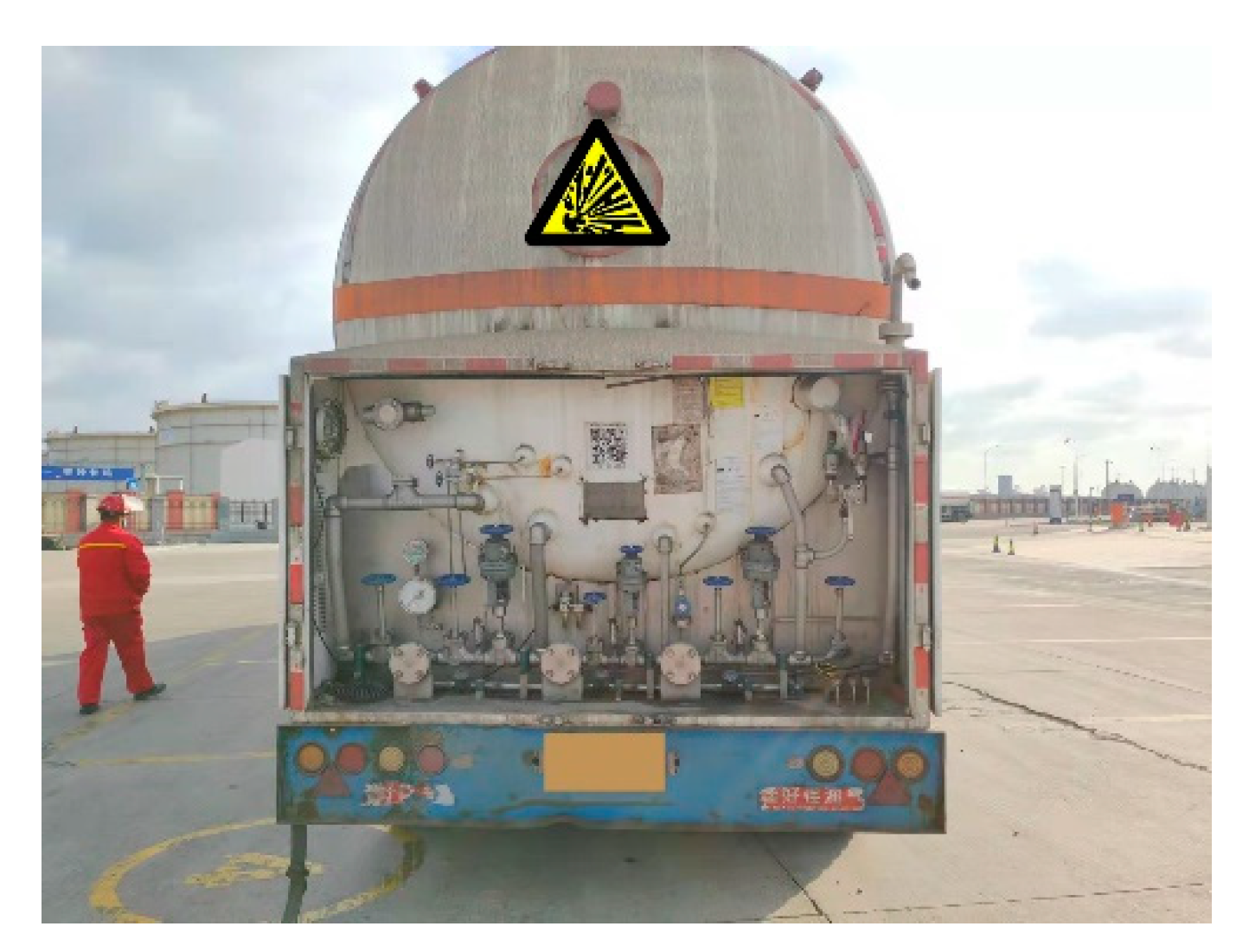
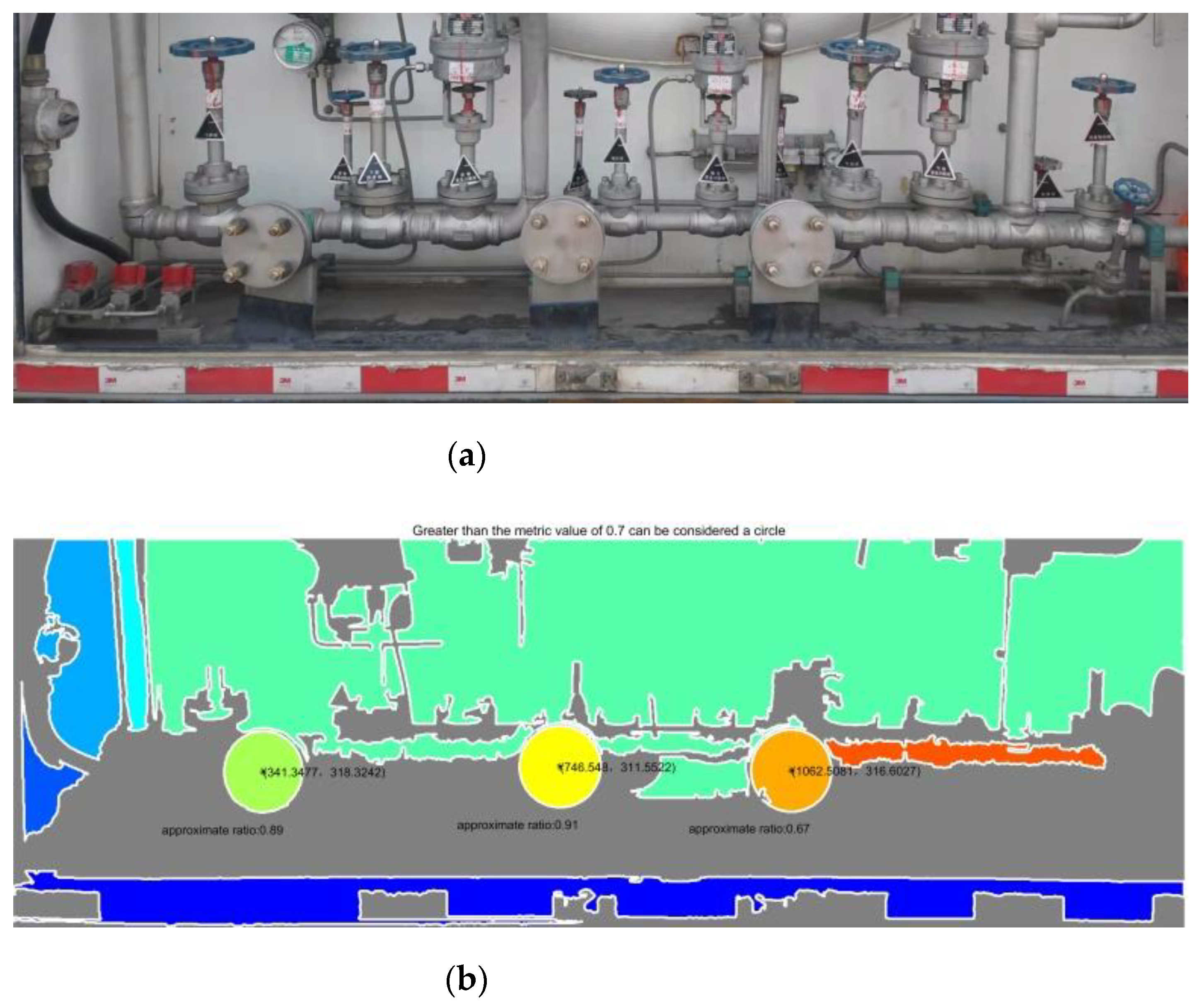
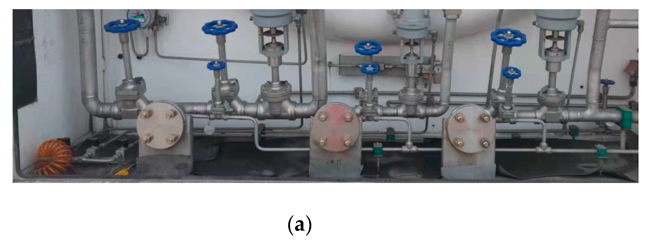
5.3. Detection Experiment of Flange Port of Tank Car
In this experiment, the tank car flange was detected using an on-site image of the tank car. Figure 12 shows a rear-view image of a typical in-service tank car. In the automatic docking system, the preset initial point of the small crane tube was 1.65-m high and 2-m away from the target. After adjusting the screening parameters of target circle size, flange port target detection was carried out in the specific range of the rear image of the tank car.
Figure 12.
LNG tank car rear.
In order to verify the effectiveness of the method, this paper conducted detection experiments on multiple groups of image data. Figure 13, Figure 14 and Figure 15 show the original images of three groups of experimental images and the detection results. Taking Figure 13a as an example, with the lower left corner of the image as the origin point, the measured pixel coordinates of the flange port center are [210.74, 370.41], [621.00, 365.71], and [1048.78, 388.04], respectively. After coordinate transformation, , in which is the pixel coordinate, is the camera internal parameter, is the camera external parameter, and is the camera coordinate. The internal XOY coordinates of the world-scale camera coordinate system are [32.20, 53.61], [91.63, 55.87], and [151.80, 57.17]. The z-axis coordinates, namely the distance, are detected by other sensors.

Figure 13.
On-site tank car A. (a) Flange practicality picture. (b) Detection results of (a).
Figure 14.
On-site tank car B. (a) Flange practicality picture. (b) Detection results of (a).

Figure 15.
On-site tank car C. (a) Flange practicality picture. (b) Detection results of (a).
The results show that the center of the flange face can still be located accurately in field working conditions, and the lowest running time is 0.694 s. This method detects the center and diameter of multiple images, and the outer diameter of the tested flange is actually 165 mm. It can be seen from Table 2 that the diameter accuracy errors detected by the three groups of experiments are all less than 3 mm and the accuracy errors are affected by differences in the approximation ratio. The higher the average approximation ratio is, the lower the accuracy error is. The results show that the proposed method can effectively locate the target flange position in actual field conditions and meet the real-time measurement requirements of project engineering, providing technical support for practical engineering applications.
Table 2.
On-site flange detection results.
Using the flange picture data set, real item images, and the field conditions simulation, the flange end face pose in the process of the automatic butt joint of a small crane tube was detected.
6. Conclusions
To solve the problem of target flange identification and positioning in the automatic docking system of a small crane tube, this paper proposes a method of flange port detection applicable to the automatic docking system of small crane tubes of tank cars. The system framework, algorithm principle, and realization process of this method are introduced. The space pose detection program of the flange end face is written. Additionally, the method was tested for circle center detection calibration, flange end face image detection, and the detection of the flange port of on-site tank cars. The experimental results show that the maximum error of the circle center detection accuracy is 1.503 mm and the maximum error of the diameter detection accuracy is 2.895 mm, which are less than the 3 mm range required by mechanical installation tolerance, meeting the needs of automatic on-site butt joint. At present, the detection system is limited by the requirements of explosion proof application, and the real-time image acquisition experiment is difficult to carry out on site, but we are carrying out the assembly of explosion-proof facilities in the laboratory. After the installation of explosion-proof facilities in the laboratory meets the requirements, we will carry it out on-site.
This paper conducted research on the automatic docking of bottom loading tank cars with a small crane tube via flange space position detection. In the future, when this method is applied in complex conditions, we should further improve the speed and accuracy of the algorithm and the stability of the system in order to meet the high demands of the automatic docking of bottom loading tank cars.
Author Contributions
Data curation, Z.L., Z.M. and M.X.; Formal analysis, Z.L.; Funding acquisition, M.L. and S.L.; Project administration, M.L.; Software, Z.L. and J.L.; Writing—original draft, Z.L.; Writing—review & editing, M.L. and S.L. All authors have read and agreed to the published version of the manuscript.
Funding
This research was funded by Key R & D Plan Industry Prospect and Key Core Technology Project of Jiangsu Province (BE2021066), Open Fund Project of Jiangsu Institute of Marine Resources Development (JSIMR201904, JSIMR201810), and Regional Leading Research Center of NRF and MOCIE (NRF-2019R1A5A8083201).
Institutional Review Board Statement
Not applicable.
Informed Consent Statement
Not applicable.
Data Availability Statement
Not applicable.
Acknowledgments
This work is supported by the key R & D plan industry prospect and key core technology project of Jiangsu Province (BE2021066), the open fund project of the Jiangsu Institute of Marine Resources development (JSIMR201904, JSIMR201810), and the Regional Leading Research Center of NRF and MOCIE (NRF-2019R1A5A8083201).
Conflicts of Interest
The authors declare no conflict of interest.
References
- Li, G.; He, Y. On the selection of the closed and quantitative loading method of large and small crane tubes for railway transportation of light oil products. Chem. Manag. 2017, 32, 14. [Google Scholar]
- Shao, Y.L.; Soh, K.Y.; Wan, Y.D.; Huang, Z.F.; Islam, M.R.; Chua, K.J. Multi-objective optimization of a cryogenic cold energy recovery system for LNG regasification. Energy Convers. Manag. 2021, 244, 114524. [Google Scholar] [CrossRef]
- Jones, K.; Sun, M.; Lin, C. Integrated analysis of LNG tank superstructure and foundation under lateral loading. Eng. Struct. 2021, 253, 113795. [Google Scholar] [CrossRef]
- Wang, Q.R. Automatic Docking Hose-Type Aerial Refueling Interface: China. CN Patent 205396560U, 27 July 2016. [Google Scholar]
- Gu, S.G.; Shao, Y.S.; Zhou, B. Electronic Control System Suitable for Automatic Docking of Marine Loading and Offloading Arms: China. CN Patent 111678039A, 18 September 2020. [Google Scholar]
- Wang, X.Z.; Fang, S.H.; Wei, J. Automatic Docking Equipment for Loading and Unloading Arms of Oil Pipelines and Ship Flanges: China. CN Patent 207386981U, 22 May 2018. [Google Scholar]
- Zhang, B.; Yin, X.K.; Zhao, J.Y. Fully Automatic Alignment Fluid Loading and Unloading Arm and Its System: China. CN Patent 207386981U, 30 August 2019. [Google Scholar]
- Gao, H.; Chen, Q.; Liu, C.; Gu, G. High dynamic range infrared image acquisition based on an improved multi-exposure fusion algorithm. Infrared Phys. Technol. 2021, 115, 103698. [Google Scholar] [CrossRef]
- Saliu, I.S.; Satyanarayana, B.; Fisol, M.A.B.; Wolswijk, G.; Decannière, C.; Lucas, R.; Otero, V.; Dahdouh-Guebas, F. An accuracy analysis of mangrove tree height mensuration using forestry techniques, hypsometers and UAVs. Estuar. Coast. Shelf Sci. 2020, 248, 106971. [Google Scholar] [CrossRef]
- Cao, C.; Gao, J.; Liu, Y.C. Research on space fusion method of millimeter wave radar and vision sensor. Procedia Comput. Sci. 2020, 166, 68–72. [Google Scholar] [CrossRef]
- Ansarinasab, H.; Hajabdollahi, H.; Fatimah, M. Conceptual design of LNG regasification process using liquid air energy storage (LAES) and LNG production process using magnetic refrigeration system. Sustain. Energy Technol. Assess. 2021, 46, 101239. [Google Scholar] [CrossRef]
- Chen, G.L.; Cheng, Q.L.; Hong, H.B. Automatic docking position and attitude adjustment method of spacecraft module based on multi-sensor measurement. J. Beihang Univ. 2019, 45, 1232–1239. [Google Scholar] [CrossRef]
- Cheng, X.; Sun, J.; Zhou, F.; Xie, Y. Shape from apparent contours for bent pipes with constant diameter under perspective projection—Science direct. Measurement 2021, 182, 109787. [Google Scholar] [CrossRef]
- Msa, C.; Skb, B.; Skp, C. Geometric least square curve fitting method for localization of wireless sensor network. Ad Hoc Netw. 2021, 116, 102456. [Google Scholar] [CrossRef]
- Heikkila, J. Geometric camera calibration using circular control points. IEEE Trans. Pattern Anal. Mach. Intell. 2000, 22, 1066–1077. [Google Scholar] [CrossRef] [Green Version]
- Liu, Z.; Liu, X.; Duan, G.; Tan, J. Precise hand-eye calibration method based on spatial distance and epipolar constraints. Robot. Auton. Syst. 2021, 145, 103868. [Google Scholar] [CrossRef]
- Zhang, Z. A flexible new technique for camera calibration. IEEE Trans. Pattern Anal. Mach. Intell. 2000, 22, 1330–1334. [Google Scholar] [CrossRef] [Green Version]
- Barros Wysterlânya, K.P.; Dias Leonardo, A.; Fernandes Marcelo, A.C. Fully Parallel Implementation of Otsu Automatic Image Thresholding Algorithm on FPGA. Sensors 2021, 21, 4151. [Google Scholar] [CrossRef] [PubMed]
- Liang, Z.J.; Zhong, J. Improvement of Adaptive Canny Algorithm Based on Otsu Algorithm and Histogram Analysis. Mod. Electron. Technol. 2019, 42, 54–58. [Google Scholar] [CrossRef]
- Bellandi, P.; Docchi, F. Roboscan: A combined 2d and 3d vision system for improved speed and flexibility in pick-and-place operation. Int. J. Adv. Manuf. Technol. 2013, 69, 1873–1886. [Google Scholar] [CrossRef]
Publisher’s Note: MDPI stays neutral with regard to jurisdictional claims in published maps and institutional affiliations. |
© 2022 by the authors. Licensee MDPI, Basel, Switzerland. This article is an open access article distributed under the terms and conditions of the Creative Commons Attribution (CC BY) license (https://creativecommons.org/licenses/by/4.0/).